
Manuels Connexes pour Ecolab EcoAdd


Sommaire des Matières pour Ecolab EcoAdd
- Page 1 Betriebsanleitung Operating Instructions Manuel d’utilisation EcoAdd Ecolab Dynamic Pump GERMAN ENGLISH FRANÇAIS 417102276 EcoAdd Rev. 5-02.2020 03.02.2020...
- Page 2 Betriebsanleitung EcoAdd Ecolab Dynamic Pump EcoAdd 417102276 Rev. 5-02.2020 03.02.2020 DEUTSCH...
-
Page 3: Table Des Matières
1.1.4 Symbole, Hervorhebungen und Aufzählungen..........11 1.1.5 Markenrechte von Drittanbietern..............12 1.1.6 Urheberschutzhinweis................... 12 1.2 Transport......................13 1.3 Reparaturen / Rücksendungen an Ecolab Engineering GmbH......14 1.3.1 Rücksendebedingungen................14 1.4 Verpackung....................... 15 1.5 Lagerung......................16 1.6 Gerätekennzeichnung - Typenschild..............16 1.7 Gewährleistung.................... - Page 4 Inhaltsverzeichnis Beschreibung der Pumpe..................38 5.1 Identifizierung der Pumpe - Typenschilder............38 5.2 Anschlussbuchsen / Kabeldurchführungen............39 5.3 Pumpenkopfvarianten..................40 Montage und Installation..................41 6.1 Allgemeines und Sicherheit................41 6.2 Montagevarianten..................... 43 6.2.1 Standmontage- oder Bodenmontage............. 44 6.2.2 Wandmontage....................45 6.3 Hydraulische Installation...................
- Page 5 Inhaltsverzeichnis 7.7 Hauptmenü....................... 72 7.7.1 Hauptmenü aufrufen..................72 7.7.2 Hauptmenü bei eingeschaltetem Zutrittscode aufrufen......... 73 7.8 Dosiermodus..................... 73 7.8.1 [Dosiermodus] [V-variabel]................76 7.9 Betriebsart......................77 7.9.1 [Betriebsart] [Manuell]..................78 7.9.2 Betriebsart [Manuell] (mit „Dosierfreigabe“ )..........78 7.9.3 Betriebsart [Impuls]..................80 7.9.3.1 [Betriebsart] [Impuls] - Konzentration............
- Page 6 10.2.2 Error Codereihe 200.................. 152 10.2.3 Error Codereihe 300.................. 153 10.2.4 Error Codereihe 400.................. 154 10.2.5 Error Codereihe 500.................. 154 10.3 Reparaturen / Rücksendungen an Ecolab Engineering GmbH....155 10.3.1 Rücksendebedingungen................155 Wartung......................... 156 11.1 Wartungsmodus - Servicestellung der Pumpe - [Pumpenservice]....157 11.1.1 Pumpe in den Wartungsmodus versetzen, wenn kein Zutrittscode...
- Page 7 12.1.2 Verschleißteilset 30 l/h, 50 l/h und 120 l/h..........170 12.2 Ersatzteile..................... 170 12.2.1 Ersatzteilbaugruppen................. 170 12.2.1.1 Steuerteil „EcoAdd“ , komplett..............170 12.2.1.2 Display Cover - Steuerteil „EcoAdd“ ............171 12.2.2 Pumpenkopf 5 l/h..................172 12.2.3 Pumpenkopf 11 l/h..................173 12.2.4 Pumpenkopf 30 l/h und 50 l/h..............174 12.2.5 Pumpenkopf 120 l/h...................
- Page 8 Inhaltsverzeichnis 15.2 Demontage....................195 15.3 Reparaturen / Rücksendungen an Ecolab Engineering GmbH....196 15.3.1 Rücksendebedingungen................196 15.4 Entsorgung und Umweltschutz..............197 CE-Erklärung / Konformitätserklärung............... 198 417102276 Rev. 5-02.2020...
-
Page 9: Allgemeines
Im Lieferumfang dieser Pumpe befindet sich eine Kurzanleitung. Diese Kurzanleitung steht zusätzlich zum Download bereit, falls Sie diese verlegt haben oder um immer die aktuellste Version zur Verfügung zu haben. Download der Kurz-Betriebsanleitung (Artikel Nr. 417102268): https://www.ecolab-engineering.de/fileadmin/download/ bedienungsanleitungen/dosiertechnik/Dosierpumpen/ 417102268_KurzBA_EcoPro_EcoAdd.pdf 417102276 Rev. 5-02.2020... -
Page 10: Betriebsanleitungen Mit Smartphones / Tablets Aufrufen
Rufen sie den "Google Play Store" mit Ihrem Smartphone /Tablet auf. Geben Sie den Namen „Ecolab DocuAPP“ im Suchfeld ein. Wählen Sie anhand des Suchbegriffes Ecolab DocuAPP in Verbindung mit diesem Symbol die „Ecolab DocuApp“ aus. Betätigen Sie den Button [installieren]. -
Page 11: Installation Der „Docuapp" Für Ios (Apple)
1.1.2 Auswertung, Überwachung & Steuerung mit Smartphones Wenn die „EcoAdd“ mit einer Bluetooth Zusatzplatine erweitert und auf dem Smartphone die „Ecolab EcoAPP“ installiert wurde, ist ein Datenaustausch zwischen Pumpe und Smartphone möglich. Eine nähere Beschreibung befindet sich in der Softwarebeschreibung der „EcoAPP“... -
Page 12: Symbole, Hervorhebungen Und Aufzählungen
Allgemeines 1.1.4 Symbole, Hervorhebungen und Aufzählungen Symbole, Sicherheitshinweise Sicherheitshinweise sind in dieser Anleitung durch Symbole gekennzeichnet. Die Sicherheitshinweise werden durch Signalworte eingeleitet, die das Ausmaß der Gefährdung zum Ausdruck bringen. VORSICHT! Diese Kombination aus Symbol und Signalwort weist auf eine möglicherweise gefährliche Situation hin, die zu geringfügigen oder leichten Verletzungen führen kann, wenn sie nicht gemieden wird. -
Page 13: Markenrechte Von Drittanbietern
Weitergabe oder Kopieren dieses Dokuments sowie die Verwendung und Weitergabe von Informationen über dessen Inhalt ist nur nach ausdrücklicher Genehmigung erlaubt. Alle Verletzungen ziehen Schadenersatzforderungen nach sich. Ecolab Engineering GmbH behält sich alle Rechte bei Gewährung eines Patentes oder der Eintragung eines Gebrauchsmusters vor. Urheberschutz Diese Anleitung ist urheberrechtlich geschützt. -
Page 14: Transport
Allgemeines Transport Die Abmessungen der Verpackung und das Verpackungsgewicht entnehmen Sie bitte dem Kapitel "Technische Daten". Unsachgemäßer Transport HINWEIS! Sachschäden durch unsachgemäßen Transport! Bei unsachgemäßem Transport können Transportstücke fallen oder umstürzen. Dadurch können Sachschäden in erheblicher Höhe entstehen. – Beim Abladen der Transportstücke bei Anlieferung sowie bei innerbetrieblichem Transport vorsichtig vorgehen und die Symbole und Hinweise auf der Verpackung beachten. -
Page 15: Reparaturen / Rücksendungen An Ecolab Engineering Gmbh
Füllen Sie alle Angaben aus und folgen Sie der weiteren Navigation. Folgende Dokumente müssen ausgefüllt werden: – Rücksendeformular: – Fordern Sie das Formular bei Ecolab an. – Füllen Sie es vollständig und korrekt aus. – Füllen Sie die Unbedenklichkeitserklärung aus. -
Page 16: Verpackung
Allgemeines Verpackung Die einzelnen Packstücke sind entsprechend den zu erwartenden Transportbedingungen verpackt. Für die Verpackung wurden ausschließlich umweltfreundliche Materialien verwendet. Die Verpackung soll die einzelnen Bauteile bis zur Montage vor Transportschäden, Korrosion und anderen Beschädigungen schützen. Daher die Verpackung nicht zerstören und erst kurz vor der Montage entfernen. UMWELT! Gefahr für die Umwelt durch falsche Entsorgung! Verpackungsmaterialien sind wertvolle Rohstoffe und können in vielen... -
Page 17: Lagerung
Allgemeines Lagerung Unter Umständen befinden sich auf den Packstücken Hinweise zur Lagerung, die über die hier genannten Anforderungen hinausgehen. Diese sind entsprechend einzuhalten. Folgende Lagerbedingungen sind zu beachten: Nicht im Freien aufbewahren. Trocken und staubfrei lagern. Keinen aggressiven Medien aussetzen. Vor Sonneneinstrahlung schützen. -
Page 18: Kontakte
Allgemeines Kontakte 1.8.1 Service- und Kontaktadresse zum Hersteller Ecolab Engineering GmbH Raiffeisenstraße 7 D-83313 Siegsdorf Telefon (+49) 86 62 / 61 0 Telefax (+49) 86 62 / 61 166 Email: engineering-mailbox@ecolab.com http://www.ecolab-engineering.com 1.8.2 Kontakt Technischer Kundendienst Wenn Sie sich an den technischen Kundendienst wenden, stellen Sie sicher, dass Sie den Typencode in der E-Mail vermerken. -
Page 19: Sicherheit
Sicherheit Sicherheit Allgemeine Sicherheitshinweise GEFAHR! Wenn anzunehmen ist, dass ein gefahrloser Betrieb nicht mehr möglich ist, so ist die Pumpe unverzüglich außer Betrieb zu setzen und gegen unabsichtlichen Betrieb zu sichern. Das ist der Fall: – wenn sichtbare Beschädigungen erkennbar sind, –... -
Page 20: Vernünftigerweise Vorhersehbare Fehlanwendungen
Sicherheit WARNUNG! Gefahr bei Fehlgebrauch! Fehlgebrauch kann zu gefährlichen Situationen führen: – Niemals andere Dosiermedien als das vorgegebene Produkt verwenden. – Niemals die Dosiervorgaben des Produkts über den tolerierbaren Bereich hinaus verändern. – Niemals in explosionsgefährdeten Bereichen verwenden. – Installations-, Wartungs und Repararturarbeiten nur durch dafür qualifizierte Personen durchführen lassen. -
Page 21: Eigenmächtiger Umbau Und Ersatzteilherstellung
Folgen aus. Dosiermedien VORSICHT! Verwendung von Dosiermedien: – Das Dosiersystem darf nur mit von Ecolab validierten Produkten verwendet werden. – Die für den bestimmungsgemäßen Betrieb einzusetzenden Materialien / Medien werden durch den Betreiber beschafft und eingesetzt. – Die sachgerechte Behandlung dieser Materialien / Medien und die damit verbundenen Gefahren unterliegen der alleinigen Verantwortung des Betreibers. -
Page 22: Sicherheitsdatenblätter
Maßnahmen für den Schutz der Gesundheit und die Sicherheit am Arbeitsplatz treffen kann. Der hohe Stellenwert des Sicherheitsdatenblattes und die damit verbundene Verantwortung ist sich Ecolab bewusst. Die von Ecolab zur Verfügung gestellten Sicherheitsdatenblätter unterliegen einer ständigen Kontrolle. Somit wird gewährleistest, dass zu jeder Zeit die aktuellen Informationen vorhanden sind. -
Page 23: Betreiberpflichten
Kompensatoren, um die Belastungen während der Aufstellung und des Betriebs zu minimieren. Falls die Aufstellung nicht vom Kundendienst / Service der Ecolab Engineering GmbH durchgeführt wird, muss sichergestellt werden, dass die Rohre und Dosierleitungen aus den korrekten Materialien bestehen und in Bezug auf Länge und Durchmesser den Anforderungen entsprechen. -
Page 24: Personalanforderungen
Sicherheit die Beleuchtung der Arbeitsplätze ist betreiberseitig laut DIN EN 12464-1 (im Geltungsbereich der Bundesrepublik Deutschland) herzustellen. Beachten Sie die bei Ihnen gültigen Vorschriften! sicherzustellen, dass bei der Montage und Inbetriebnahme, wenn diese vom Betreiber selbst durchgeführt werden, örtliche Vorschriften beachtet werden. Personalanforderungen Qualifikationen GEFAHR! -
Page 25: Servicepersonal Des Herstellers
Sicherheit Servicepersonal Bestimmte Arbeiten dürfen nur durch Servicepersonal des Herstellers oder durch vom Hersteller autorisiertes oder speziell darauf geschultes Servicepersonal durchgeführt werden. Andere Personen, bzw. anderes Personal ist nicht befugt, diese Arbeiten auszuführen. Zur Ausführung dieser anfallenden Arbeiten kontaktieren Sie unseren Kundenservice. Hilfspersonal ohne besondere Qualifikation GEFAHR! Hilfspersonal ohne besondere Qualifikation, bzw. -
Page 26: Persönliche Schutzausrüstung (Psa)
Sicherheit Persönliche Schutzausrüstung (PSA) GEFAHR! Persönliche Schutzausrüstung, im folgenden PSA genannt, dient dem Schutz des Personals. Die auf dem Produktdatenblatt (Sicherheitsdatenblatt) des Dosiermediums beschriebene PSA ist unbedingt zu verwenden. Chemikalienbeständige Schutzhandschuhe Chemikalienbeständige Schutzhandschuhe dienen zum Schutz der Hände vor aggressiven Chemikalien. Schutzbrille Die Schutzbrille dient zum Schutz der Augen vor umherfliegenden Teilen und Flüssigkeitsspritzern. - Page 27 Sicherheit GEFAHR! Lebensgefahr durch elektrischen Strom! Bei Berührung mit spannungsführenden Teilen besteht unmittelbare Lebensgefahr durch Stromschlag. Beschädigung der Isolation oder einzelner Bauteile kann lebensgefährlich sein. – Arbeiten an elektrischen Bauteilen nur von Elektrofachkräften ausführen lassen. – Vor Beginn der Arbeiten, spannungsfreien Zustand herstellen und für die Dauer der Arbeiten sicherstellen.
- Page 28 Sicherheit Unbefugter Zutritt GEFAHR! Unbefugter Zutritt Der Betreiber hat sicherzustellen, dass das Betreten des Bedienbereiches durch unbefugte Personen verhindert wird. Gefahren durch Chemie (Dosiermedium/Wirkstoff) GEFAHR! Verletzungsgefahr durch die angewendete Chemie (Dosiermedium) an Haut und Augen. – Vor Verwendung des Dosiermediums das beiliegende Sicherheitsdatenblatt aufmerksam lesen.
- Page 29 Sicherheit Sollten Sie nicht sicher sein, ein aktuelles Sicherheitsdatenblatt vorliegen zu haben, wenden Sie sich bitte an Ihren Ecolab Fachberater. Er wird Ihnen gerne weiterhelfen, damit die Maßnahmen zum ständigen Schutz der Gesundheit am Arbeitsplatz gewährleistet sind. GEFAHR! Die Sicherheitsdatenblätter müssen nahe am Gerät bzw. nahe an den Gebinden ausgehängt werden, damit im Falle eines Unfalles schnell die...
-
Page 30: Wichtige Sicherheitseinstellungen
® der „EcoAPP“ und der Membrandosierpumpe „EcoAdd“ via Bluetooth verantwortlich. Die nachfolgend aufgeführten Sicherheitshinweise müssen eingehalten werden. Ecolab übernimmt keinerlei Haftung bei Schäden, die durch nicht Beachtung entstehen. Hinweise zur Datenübertragung und Nutzung von Bluetooth ® Aktualisieren des Betriebssystems am verwendeten Smartphone oder Tablet: Viele Angriffe nutzen Schwachstellen in den Betriebssystemen und veralteten ®... -
Page 31: Installations-, Wartungs- Und Reparaturarbeiten
Sicherheit Kontrolle der aktiven Geräte in der Bluetooth ® Übersicht: Nur bekannte Geräte mit dem Smartphone oder Tablet verbinden. Sollten sich unbekannte Geräte verbinden wollen, sollten diese erst überprüft, bzw. identifiziert und ggf. abgelehnt werden Auf weitere Geräte im Empfangsbereich achten! Pairing mit anderen Geräten nur durchführen, wenn sich keine anderen (unbekannten) Geräte im Empfangsbereich befinden und automatische Kopplungen prüfen. -
Page 32: Lieferumfang Und Zubehör
PFC = Pumpenkopf: PP, O-Ringe: FKM, Ventilkugel: Keramik PEC = Pumpenkopf: PP, O-Ringe: EPDM, Ventilkugel: Keramik DFC = Pumpenkopf: PVDF, O-Ringe: FKM, Ventilkugel: Keramik DEC = Pumpenkopf: PVDF, O-Ringe: EPDM, Ventilkugel: Keramik Ecolab Dynamic Pump: „EcoAdd“ (mit Bluetooth ) Leistung Pumpenschlüssel Art. Nr. -
Page 33: Zubehör
Ä Kapitel 1.1 „Hinweise Siehe auch: zur Betriebsanleitung“ auf Seite 8 Zubehör Darstellung Beschreibung Artikel Nr. EBS Nr. Bluetooth Platine zur Aufrüstung der „EcoAdd“ : 252080 auf Anfrage Zur Verwendung der Pumpe werden entsprechende Schlauchanschlüsse aus dem Zubehör benötigt. Darstellung Beschreibung Artikel Nr. -
Page 34: Funktionsbeschreibung
Funktionsbeschreibung Funktionsbeschreibung Bei der Membrandosierpumpe „EcoAdd“ handelt es sich um elektromotorisch betriebene Membrandosierpumpen für die Förderung von sauberen, nicht abrasiven Dosiermedien. Durch die hier eingesetzte Schrittmotortechnik kann sowohl die Saughubdauer als auch die Dosierhubdauer getrennt voneinander eingestellt werden. Dadurch ergeben sich eine Reihe von Vorteilen wie z.B. ein großer Einstellbereich, eine nahezu kontinuierliche und pulsationsarme Dosierung, oder auch die Möglichkeit auf... - Page 35 Funktionsbeschreibung Formeln zur Berechnung: Abb. 3: Grafische Darstellung der Formel Dosierhubdauer Dosierleistung ¦ Hubfrequenz Saughubdauer Hubvolumen Zeit Beispielrechnung mit einer Pumpe: Typ 00510x: Die Werte für die Formel können aus den nachfolgenden Tabellen entnommen werden. 417102276 Rev. 5-02.2020...
- Page 36 Funktionsbeschreibung Dosiermodus Standard Mittel Niedrig Variabel Display 00510x 5 l/h 4,17 l/h 3,33 l/h 2,5 - 5 l/h 01110S 11,0 l/h 9,17 l/h 7,33 l/h 5,5 - 11,0 l/h Dosierleistung 100 % 03003S 30 l/h 25 l/h 20 l/h 15 - 30 l/h 05010M 50 l/h 41,7 l/h...
-
Page 37: Ausstattungsmerkmale - „Ecoadd
Funktionsbeschreibung Der Aufbau wurde so gewählt, dass ein Wechsel zwischen den Bedienteilen von „EcoPro“ und „EcoAdd“ sehr einfach möglich ist. Des weiteren können die Bedienteile variabel auf dem Gehäuse gedreht werden Ä Kapitel 13.1.1 „Drehen des Steuerteils“ auf Seite 177. -
Page 38: Elektronische Zusatzfunktionen
Funktionsbeschreibung 4.1.1 Elektronische Zusatzfunktionen PLUS Dosierüberwachung (in Verbindung mit Ovalradzähler „OGM “ ) Dosierregelung (in Verbindung mit Ovalradzähler „OGM PLUS “ ) Bluetoothmodul für Kommunikation zwischen Pumpe und Smartphone Auswertung, Überwachung & Steuerung mit einem Smartphone Wenn die Pumpe mit einer Bluetooth Zusatzplatine erweitert und auf dem Smartphone die zum Betriebssystem des verwendeten Smartphones passende „EcoApp“... -
Page 39: Beschreibung Der Pumpe
Beschreibung der Pumpe Beschreibung der Pumpe Abb. 4: Aufbau „EcoAdd“ Drehbares Bedienteil Montageplatte Ein-, Aus-Taster Kabeldurchführung für Netzkabel / Netzanschluss USB-Buchse Sauganschluss / Saugventil Eingabe-Display (Touch-Screen) 10 Pumpenkopf Kabeldurchführungen und Anschlüsse (hinter Druckanschluss / Druckventil Displaydeckel) 12 Entlüftungsschraube Typenschild Identifizierung der Pumpe - Typenschilder Die Pumpe ist mit einem Typenschild (Abb. -
Page 40: Anschlussbuchsen / Kabeldurchführungen
Beschreibung der Pumpe Anschlussbuchsen / Kabeldurchführungen Abb. 5: Anschlüsse „EcoAdd“ Kabeldurchführung für Netzkabel / Netzanschluss Niveauüberwachung (Sauglanzenanschluss) 2-5 Kabeldurchführungen zur Hauptplatine mit Anschlussklemmen Ä Kapitel 6.4 „Elektrische Installation“ auf Seite 55 Der Anschluss ist in beschrieben. Zulässige Kabel-Außendurchmesser für Anschluss der EIN/Ausgänge: AD Ø... -
Page 41: Pumpenkopfvarianten
Beschreibung der Pumpe Pumpenkopfvarianten Je nach Ausführung des Pumpenkopfes und der Dosierventile, wird die Literleistung der Pumpe definiert. Die Anschlussvarianten sind in Ä Kapitel 6.3.2 „Anschluss von Saug- und Druckleitungen (Dosierleitungen)“ auf Seite 50 und die Wartung in Ä Kapitel 11 „Wartung“ auf Seite 156 beschrieben. Ersatzteile können Ä... -
Page 42: Montage Und Installation
Montage und Installation Montage und Installation Personal: Mechaniker Elektrofachkraft Servicepersonal Fachkraft Schutzausrüstung: Schutzhandschuhe Schutzbrille Sicherheitsschuhe Allgemeines und Sicherheit HINWEIS! Generelle Anweisungen zur Installation und Montage: – Die Pumpe muss an einer gut zugänglichen, frostgeschützten Stelle montiert werden. – Die in den "Technischen Daten" angegebenen Umgebungsbedingungen müssen eingehalten werden . - Page 43 Montage und Installation GEFAHR! Gefahren durch elektrischen Strom sind mit nebenstehendem Symbol gekennzeichnet. Arbeiten an solchen Stellen dürfen ausschließlich durch ausgebildetes und authorisiertes Fachpersonal durchgeführt werden. WARNUNG! Der Schutzleiteranschluss ist an den Anschlussstellen durch dieses Symbol gekennzeichnet. GEFAHR! Lebensgefahr durch elektrischen Strom! Bei Berührung mit spannungsführenden Teilen besteht unmittelbare Lebensgefahr durch Stromschlag.
-
Page 44: Montagevarianten
Montage und Installation VORSICHT! Weder die Überströmleitung, noch die Entlüftungsleitung darf in die Saugleitung der Dosierpumpe zurückgeführt werden! Achten Sie darauf, dass beim Anschluss der Saug- und Druckleitung die O-Ringe auf den Anschlüssen montiert sind, um die notwendige Abdichtung zu erreichen. Einige der in diesem Kapitel dargestellten Grafiken sind Prinzipskizzen, die den generellen Einbau darstellen sollen. -
Page 45: Standmontage- Oder Bodenmontage
Montage und Installation 6.2.1 Standmontage- oder Bodenmontage Abb. 8: Vorbereitungen zur Standmontage Für die Standmontage werden ausschließlich Halteelemente (im Lieferumfang) mit der Kennzahl 1 (Abb. 8, Pos. 2) verwendet. Montageplatte umdrehen Halteelemente von hinten in die vier Öffnungen mit der Bezeichnung "table" (= Tisch / Standmontage) stecken und einrasten lassen. -
Page 46: Wandmontage
Montage und Installation 6.2.2 Wandmontage Abb. 9: Vorbereitungen zur Wandmontage Für die Wandmontage werden Halteelemente (im Lieferumfang) mit der Kennzahl 1 (Abb. 9, Pos. 2) und der Kennzahl 2 (Abb. 9, Pos. 3) verwendet. Montageplatte umdrehen. Halteelemente (Kennzahl: 1, Abb. 9, Pos. 2) von hinten in die zwei oberen Öffnungen mit der Bezeichnung "wall"... -
Page 47: Hydraulische Installation
Montage und Installation Hydraulische Installation Personal: Mechaniker Servicepersonal Fachkraft Schutzausrüstung: Chemikalienbeständige Schutzhandschuhe Schutzbrille Sicherheitsschuhe Abb. 10: Einbauschema Überströmventil Druckventil Druckhalteventil Pumpenkopf Optional: Mehrfunktionsventil (MFV) Saugventil Sauglanze bzw. Bodensaugventil Verwendung eines Mehrfunktionsventils (MFV): Dosier-, Druckhalte- und Überdruckventile (Pos. 1 und Pos. 2), können durch ein Mehrfunktionsventil (MFV) (Pos. -
Page 48: Installationsbeispiele
Montage und Installation 6.3.1 Installationsbeispiele Hydraulische Installation Bei Medien, die zu Sedimentation neigen, muss das Bodensaugventil bzw. Fußventil der Saugleitung oder der Sauglanze über der zu erwartenden Schlammschicht montiert sein. Begriffsdefinition: Leerhebern Von Leerhebern, spricht man immer dann, wenn der maximale Flüssigkeitsspiegel (in diesem Fall der Entnahmebehälter) höher liegt als der tiefste Punkt der Dosierleitung. - Page 49 Montage und Installation Installationsbeispiel 2 1 Impfventil / Dosierventil 2 Druckhalteventil 3 Überströmventil Bei ausgasenden Medien oder bei Produkten mit einer Viskosität > 100 mPas empfiehlt sich die Anordnung im Zulaufbetrieb. Hierbei ist aber darauf zu achten, dass die Impfstelle (Pos. 1), oberhalb des Entnahmebehälters angeordnet ist und/oder ein entsprechendes Druckhalteventil (Pos.
- Page 50 Montage und Installation Installationsbeispiel 5 Saugleitungen sind so kurz wie möglich zu halten. Lange und verschlungene Saugleitungen können zu Luftansammlungen im System führen. Die Saughöhe darf max. 2 m und die Fließgeschwindigkeit max. 0,3 m/s betragen! Installationsbeispiel 6 Saugleitungen müssen immer steigend zum Saugventil der Dosierpumpe verlegt werden.
-
Page 51: Anschluss Von Saug- Und Druckleitungen (Dosierleitungen)
Montage und Installation 6.3.2 Anschluss von Saug- und Druckleitungen (Dosierleitungen) VORSICHT! Achten Sie darauf, dass beim Anschluss der Saug- und Druckleitung die O-Ringe auf den Anschlüssen montiert sind, um die notwendige Abdichtung zu erreichen. Zum Schutz der Dosieranlage wird die Verwendung einer Sauglanze mit Leermeldeeinrichtung und Schmutzfänger aus unserem Zubehörprogramm dringend empfohlen! Die Leermeldeeinrichtung schaltet bei Unterschreitung eines bestimmten Behälter-Niveaus die Pumpe ab. -
Page 52: Schlauchanschluss Mit Kegelteil Und Spannteil
Montage und Installation 6.3.2.2 Schlauchanschluss mit Kegelteil und Spannteil Abb. 12: Rohr- Schlauchanschluss mit Kegelteil Schlauch O-Ring Überwurfmutter Saug-, Druckventil Spannteil A1 Rohr bzw. Schlauch aufgesteckt Kegelteil B1 Ventilanschluss: Sollzustand nach Zusammenbau Schlauch (Pos. 1) gerade abschneiden. Überwurfmutter (Pos. 2) über Schlauch (Pos. 1) schieben. Spannteil (Pos. -
Page 53: Rohr- Und Schlauchanschluss Mit Aufstecknippel Und Schlauchschelle
Montage und Installation 6.3.2.3 Rohr- und Schlauchanschluss mit Aufstecknippel und Schlauchschelle Abb. 13: Rohr- und Schlauchanschluss mit Aufstecknippel und Schlauchschelle Detail/Schnitt: Einzelteildarstellung Saug-, Druckventil Schlauch Schlauchschelle Überwurfmutter A1 Rohr bzw. Schlauch aufgesteckt Kegelteil B1 Ventilanschluss: Sollzustand nach Zusammenbau O-Ring Schlauch (Pos. 1) gerade abschneiden. Überwurfmutter (Pos. -
Page 54: Rohranschluss Mit Aufschweissverbindung
Montage und Installation 6.3.2.4 Rohranschluss mit Aufschweissverbindung Abb. 14: Rohr- und Schlauchanschluss mit Aufschraubverschraubung Aufschweißverbindung Saug-, Druckventil Rohr- oder Schlauch A1 Rohr bzw. Schlauch in der Aufschweißverbindung Überwurfmutter B1 Ventilanschluss: Sollzustand nach Zusammenbau O-Ring Aufschweißverbindung (Pos. 1) mit Schlauchanschluss verschweißen. O-Ring (Pos. -
Page 55: Dosierventile Lagerichtig Einbauen
Montage und Installation 6.3.3 Dosierventile lagerichtig einbauen Personal: Mechaniker Servicepersonal Fachkraft Schutzausrüstung: Chemikalienbeständige Schutzhandschuhe Schutzbrille WARNUNG! Beim Einbau ist unbedingt darauf zu achten, dass die Ventile der Fließrichtung entsprechend eingebaut werden! Auf den Saug-/Druckventilen ist die Fließrichtung durch einen eingeprägten Pfeil dargestellt. HINWEIS! Die nachfolgend angegebenen Anzugsdrehmomente sind unbedingt einzuhalten um zum einen die Dichtigkeit des Systems und zum anderen... -
Page 56: Elektrische Installation
Fachpersonal nach den aktuell geltenden CE-Richtlinien, bzw. den jeweiligen örtlichen Vorschriften durchgeführt werden. Achten Sie unbedingt darauf die Spannungsversorgung zu trennen und gegen wiedereinschalten zu sichern! Abb. 15: Elektrische Installation „EcoAdd“ Alle vier Gehäuseschrauben lösen. Frontdeckel abnehmen. Zum erweiterten Anschluss externer Signale, die Anschlussleitungen durch die Klemmwürfel führen. -
Page 57: Übersicht Klemmenbelegung
Sämtliche Änderungen der Klemmenbelegung sind nur durch Fachpersonal zugelassen. Bei Rückfragen und für Hilfestellungen kontaktieren Sie Ä Kapitel 1.8.2 „Kontakt Technischer unseren Kundenservice Kundendienst“ auf Seite 17. Abb. 16: Klemmenbelegung „EcoAdd“ L1 Netzphase (stromführender Leiter) 15 Membranüberwachung: Membrane Nulleiter 16 Membranüberwachung: 5 Volt Alarmausgang: NC 17 Membranüberwachung: Anode... -
Page 58: Netzanschluss
Montage und Installation 6.4.2 Netzanschluss Die Netzanschlussleitung ist vom Werk aus bereits vormontiert. Sollte aufgrund der örtlichen Gegebenheiten das Netzanschlusskabel ausgetauscht werden müssen, sind unbedingt alle nachfolgenden Beschreibungen und Hinweise zu beachten. VORSICHT! – Arbeiten am Netzanschluss dürfen ausschließlich durch ausgebildetes und autorisiertes Fachpersonal durchgeführt werden. -
Page 59: Stroke] Hubsignalausgang
Montage und Installation 6.4.4 [Stroke] Hubsignalausgang Mit jedem Hub der Pumpe wird der Schaltausgang einmal geschlossen. Schaltausgang = potentialfreier Transistorausgang, Belastung 24 V, DC, 300 mA 4 = - (minus) 5 = + (plus) 6.4.5 [BUS] Interner BUS-Anschluss 6 = GND 7 = CAN L 8 = CAN H 9 = 24 V... -
Page 60: Eingang Mit Potentialfreiem Kontakt
Montage und Installation 6.4.7.1 Eingang mit potentialfreiem Kontakt 14 GND Farbe: schwarz 15 Membrane Farbe: blau 6.4.7.2 Eingang mit elektronischem Schalter (NPN) 14 GND Farbe: schwarz 15 Membrane Farbe: blau 16 5 V, DC Farbe: weiß 6.4.8 [Control] Steuereingang 6.4.8.1 Normsignaleingang [Betriebsart] / [Strom] Für die softwareseitige Konfiguration siehe: Ä... -
Page 61: Eingang Mit Dosierfreigabe [Betriebsart] / [Manuell]
Montage und Installation 6.4.8.2 Eingang mit Dosierfreigabe [Betriebsart] / [Manuell] Für die softwareseitige Konfiguration siehe: Ä Kapitel 7.9.2 „Betriebsart [Manuell] (mit „Dosierfreigabe“ )“ auf Seite 78 20 = Freigabesignal ü Farbe: 21 = GND Farbe: 6.4.8.3 Klemmenbelegung bei Verwendung eines Wasserzählers 6.4.8.3.1 "potentialfreier Kontakt"... -
Page 62: Level] Niveauüberwachung (Sauglanze)
Montage und Installation 6.4.9 [Level] Niveauüberwachung (Sauglanze) VORSICHT! Keine elektrische Spannung anschließen! 6.4.9.1 Eingang Niveauvorwarnung Schaltkontakt offen 25 GND Farbe: schwarz 27 Leermeldung Farbe: blau 6.4.9.2 Eingang Leermeldung Schaltkontakt offen 25 GND Farbe: schwarz 26 Niveauvorwarnung Farbe: braun 417102276 Rev. 5-02.2020... -
Page 63: Allgemeine Hinweise
Fachkraft Allgemeine Hinweise: – Die in diesem Kapitel beschriebene Steuerung / Software bezieht sich ausschließlich auf den Pumpentyp „EcoAdd“ . – Die dargestellten Übersichten der Menüebenen werden nur in der ersten Einstellungsebene gezeigt. – Bei den nachfolgenden Bildschirmen werden die Anzeigen exemplarisch für eine Pumpe mit 11 l/h angezeigt/angegeben. -
Page 64: Steuerung / Software
Steuerung / Software Startbildschirm Beim Einschalten der Pumpe wird für ca. fünf Sekunden folgendes angezeigt: Spezifischer Pumpenschlüssel Spezifischer Produktionscode Version der verwendeten Software Versorgungsspannung der Pumpe Verwendete Materialien für Pumpenkopf, Membrane, Dichtung, Ventile und Ventilkugel Abb. 17: Start-Bildschirm Hersteller-Logo Spezifischer Pumpenschlüssel Pumpengröße (Literleistung) Software Versionen: System/Motor/Bluetooth Materialien der Pumpenkomponenten... -
Page 65: Reinigung Des Berührungsempfindlichen Bedienfeldes (Touch-Screen)
Steuerung / Software 7.3.1 Reinigung des berührungsempfindlichen Bedienfeldes (Touch-Screen) VORSICHT! Für die Reinigung des berührungsempfindlichen Bedienfeldes empfiehlt sich die Verwendung eines Mikrofasertuches. – Keine ungeeigneten Reinigungsmittel verwenden, um die Oberfläche des Bedienfeldes nicht zu beschädigen. – Beim Reinigen nicht zuviel Druck auf das Bedienfeld ausüben, um eine Beschädigung des Drucksensors zu verhindern. -
Page 66: Bedientasten
Steuerung / Software 7.3.2 Bedientasten Symbol Beschreibung / Funktion "Hauptmenü" Taste: Hauptmenü aufrufen. "Menü" Taste: Übergeordnetes Menü aufrufen. "Weiter" Taste: Aufrufen / Anzeigen des nächsten Einstellungsdisplays. "Plus" Taste: Verstellung eines Wertes in den positiven Bereich. "Minus" Taste: Verstellung eines Wertes in den negativen Bereich. "Zeichen löschen"... -
Page 67: Bildlaufleisten, Optionsfelder, Auswahlfelder, Zahlen- Und Texteingabe
Steuerung / Software 7.3.3 Bildlaufleisten, Optionsfelder, Auswahlfelder, Zahlen- und Texteingabe Menüeinträge auf Folgeseiten mit der Bildlaufleiste darstellen: Abb. 18: Beispiel: Bildlaufleisten Durch Verschieben der Bildlaufleiste (weißer Balken, Pos. 2) können Menüeinträge, die nicht auf einer Seite dargestellt werden können, aufgerufen werden. Optionsfeld: Abb. - Page 68 Steuerung / Software Zahlen eingeben: Abb. 21: Beispiel: Eingabefeld Zahlen können in farblich dunkel hervorgehobenen Feldern (Pos. 2) eingegeben werden . Um ein Feld zur Eingabe auszuwählen, das gewünschte Eingabefeld berühren. Nicht ausgewählte Felder (Pos. 1) sind mit dem gleichen Hintergrund dargestellt wie das Display selbst.
-
Page 69: Displayansicht Im Laufenden Betrieb (Beispiel)
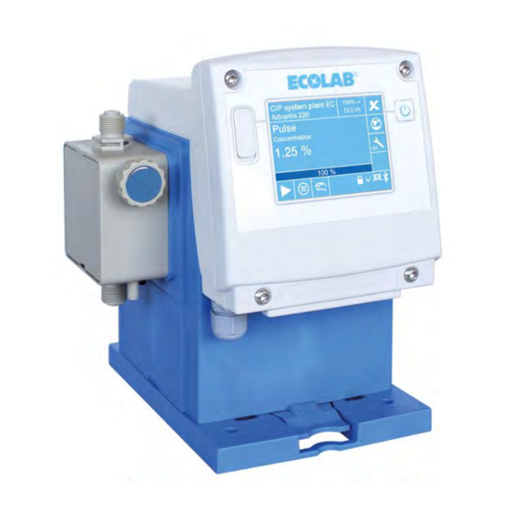
Steuerung / Software Displayansicht im laufenden Betrieb (Beispiel) Abb. 23: Betriebsanzeige (Beispiel) Pos. Bezeichnung Pumpenname Ä Kapitel 7.10.1 „Pumpenname“ auf Seite 93 Maximale Dosierleistung in l/h (abhängig vom gewählten Dosiermodus) Ä Kapitel 7.8 „Dosiermodus“ auf Seite 73 Dosiermodus (s, m, l, v) Ä... -
Page 70: Symbole Im "Laufenden Betrieb" (Betriebsmodus)
Steuerung / Software 7.4.1 Symbole im "laufenden Betrieb" (Betriebsmodus) Symbol Beschreibung Dosiermodus und Laufmeldung der Pumpe Mit jedem Hub der Pumpe blinkt die Anzeige oben rechts im Display. Der Buchstabe in der Darstellung steht für den aktuell eingestellten Dosiermodus: = standard, = Mittel;... -
Page 71: Interner Speicher
Speichergrenze der Speicherzustand grafisch auf der Betriebsebene dargestellt. Abb. 24: Interne Speicherverwaltung der EcoAdd Der Speicherzustand wird erst sichtbar, wenn einer der drei Speicherarten mindestens zu 75 % gefüllt ist. Dann ist mindestens eines der drei Felder orange (Pos. 1). -
Page 72: Menüstruktur
Steuerung / Software Menüstruktur Sollte der [Zutrittscode] aktiviert sein , beachten Sie: Ä Kapitel 7.7.2 „Hauptmenü bei eingeschaltetem Zutrittscode aufrufen“ auf Seite 73. Abb. 25: Menüstruktur 417102276 Rev. 5-02.2020... -
Page 73: Hauptmenü
Steuerung / Software Hauptmenü Sollte der [Zutrittscode] aktiviert sein , beachten Sie: Ä Kapitel 7.7.2 „Hauptmenü bei eingeschaltetem Zutrittscode aufrufen“ auf Seite 73. 7.7.1 Hauptmenü aufrufen Abb. 26: Hauptmenü ohne Zutrittscode aufrufen [Haupmenü] durch Drücken der [Menü-Taste] aufrufen. ð Der Bildschirm wechselt zum [Haupmenü]. Mit der [Scrolleiste] am rechten Bildschirmrand bis zur gewünschten Einstellung scrollen und auswählen. -
Page 74: Hauptmenü Bei Eingeschaltetem Zutrittscode Aufrufen
Steuerung / Software 7.7.2 Hauptmenü bei eingeschaltetem Zutrittscode aufrufen Abb. 27: Hauptmenü mit Zutrittscode aufrufen [Haupmenü] durch Drücken der [Menü-Taste] aufrufen. ð Der Bildschirm wechselt zur Abfrage des [Zutrittcode]. Der aktivierte [Zutrittcode] ist am Schlossysmbol erkennbar! [Zutrittcode] mit der Laufleiste eingeben (Bereich: A-Z, 0-9, sowie diverse Sonderzeichen). - Page 75 Steuerung / Software Dosiermodus Standard Mittel Niedrig Variabel Display 00510x 5 l/h 4,17 l/h 3,33 l/h 2,5 - 5 l/h 01110S 11,0 l/h 9,17 l/h 7,33 l/h 5,5 - 11,0 l/h Dosierleistung 100 % 03003S 30 l/h 25 l/h 20 l/h 15 - 30 l/h 05010M 50 l/h...
- Page 76 Steuerung / Software Abb. 28: Übersicht: Dosiermodus Werkseinstellung: Standard Auswählen des Dosiermodus: [Haupmenü] durch Drücken der [Menü-Taste] aufrufen: Ä Kapitel 7.7 „Hauptmenü“ auf Seite 72. Ä Kapitel 7.10 „Übersicht - Konfiguration“ auf Seite 92 [Konfiguration] auswählen: [Dosiermodus] auswählen. ð Bildschirm wechselt in den [Dosiermodus]. Einstellung des [Dosiermodus] auswählen: Folgende Einstellungen sind wählbar: S-standard...
-
Page 77: Dosiermodus] [V-Variabel]
Steuerung / Software 7.8.1 [Dosiermodus] [V-variabel] Abb. 29: Dosiermodus: "V-variabel" [Dosiermodus] - [V-variabel] einstellen: [Haupmenü] durch Drücken der [Menü-Taste] aufrufen: Ä Kapitel 7.7 „Hauptmenü“ auf Seite 72. Ä Kapitel 7.10 „Übersicht - Konfiguration“ auf Seite 92 [Konfiguration] auswählen: [Dosiermodus] auswählen. ð... - Page 78 Steuerung / Software Betriebsart Mit Wahl der Betriebsart wird festgelegt ob die Pumpe mit intern eingestellten Werten betrieben wird (Manuell, Timer) oder ob ein externes Signal die Dosiermenge bestimmt (Impuls, Strom). Abb. 30: Übersicht: Betriebsart Werkseinstellung: Manuell [Betriebsart] auswählen: [Hauptmenü] aufrufen: Ä...
-
Page 79: Betriebsart
Steuerung / Software 7.9.1 [Betriebsart] [Manuell] Bei der [Betriebsart] [Manuell] wird die gewünschte Dosiermenge manuell eingestellt. Nach dem Einschalten läuft die Pumpe mit der Dosierfrequenz, die der gewählten Dosiermenge entspricht. Die Dosiermenge kann auch im laufenden Betrieb umgestellt werden: Ä Kapitel 9.3 „Literleistung der Pumpe ein-, oder umstellen“ auf Seite 140. Abb. - Page 80 Steuerung / Software Schritt eins: Betriebsart in der Software auswählen: Abb. 33: Betriebsart auswählen [Hauptmenü] Taste drücken. ð Bildschirm „Hauptmenü“ wird angezeigt. [Betriebsart] auswählen. ð Auswahl „Betriebsart“ wird angezeigt. „Manuell“ auswählen. Drücken der Taste bewirkt die Speicherung und Rückkehr in das [Hauptmenü]. Drücken der Taste bewirkt die Rückkehr in die [Betriebsanzeige].
-
Page 81: Betriebsart [Impuls]
Steuerung / Software Schritt drei: Dosiermenge / Literleistung einstellen Bei den nachfolgenden Bildschirmen werden die Anzeigen exemplarisch für eine Pumpe mit 11 l/h angezeigt/angegeben. Bei anderen Pumpengrößen, weichen die Darstellungen und Angaben voneinander ab! Abb. 35: Dosiermenge / Literleistung einstellen In der [Betriebsanzeige] auf die angezeigte „Literleistung“... - Page 82 Steuerung / Software In der Betriebsart Impuls gibt es zwei Möglichkeiten der Einstellung: – Konzentration: Ä Kapitel 7.9.3.1 „[Betriebsart] [Impuls] - Konzentration“ auf Seite 84 – Menge: Ä Kapitel 7.9.3.2 „[Betriebsart] [Impuls] - Menge“ auf Seite 86 Hierbei ist folgendes zu beachten: –...
- Page 83 Steuerung / Software Softwareeinstellung: Abb. 37: Softwareeinstellung: „Impuls“ 417102276 Rev. 5-02.2020...
- Page 84 Steuerung / Software [Hauptmenü] Taste drücken. ð Bildschirm „Hauptmenü“ wird angezeigt. [Betriebsart] auswählen. ð Bildschirm zur Einstellung der [Betriebsart] wird angezeigt. [Impuls] auswählen. [ Weiter-Taste] Drücken. ð Bildschirm zur Einstellung „Impulsabstand“ wird angezeigt. Mengenangabe in Litern (vor dem Komma) mit der Laufleiste eingeben. „Mengenangabe in der Nachkommastelle“...
-
Page 85: Betriebsart] [Impuls] - Konzentration
Steuerung / Software 7.9.3.1 [Betriebsart] [Impuls] - Konzentration Bei der Einstellart Konzentration wird lediglich die gewünschte Wirkstoffkonzentration gewählt. Die Pumpensoftware errechnet daraus dann automatisch die notwendige Dosiergeschwindigkeit der Pumpe. Hierfür muss aber zuvor in der Konfigurationsebene der Impulsabstand (ml, l / Impuls) des verwendeten Durchflussmessers und die Konzentration der Dosierlösung in % eingegeben werden. - Page 86 Steuerung / Software Ä Kapitel 7.7 „Hauptmenü“ auf Seite 72 [Hauptmenü] aufrufen: [Betriebsart] - [Impuls] auswählen. [Weiter-Taste] Drücken. ð Bildschirmwechsel zur Einstellung: „Impulsabstand“ . Impulsabstand (ml, l / Impuls) des verwendeten Durchflussmessers eingebeben. Feld zur Eingabe der Nachkommastelle auswählen. ð Feldfarbe ändert sich in dunkelblau, Feld ist zur Eingabe bereit. Nachkommastelle mit der Laufzeitleiste einstellen.
-
Page 87: Betriebsart] [Impuls] - Menge
Steuerung / Software 7.9.3.2 [Betriebsart] [Impuls] - Menge Bei der Einstellart Menge wird die gewünschte Menge pro eingehenden Impuls eingegeben. Die Pumpensoftware errechnet daraus dann automatisch die notwendige Dosiergeschwindigkeit der Pumpe. Vorher muss dafür in der Konfigurationsebene bei Menüpunkt [Impulsabstand] der Wert 0 gewählt werden. Damit wird automatisch von Eingabeart „Konzentration“... -
Page 88: Betriebsart] [Strom]
Steuerung / Software 7.9.4 [Betriebsart] [Strom] Bei Betriebsart „Strom“ wird die Dosiermenge von der Höhe eines eingehenden Normsignal (0-20 mA / 4-20 mA oder invertiert 20-0 mA / 20-4 mA) bestimmt. Je nach ausgewähltem Strombereich markiert dabei der linke Stromwert die minimale Dosiermenge, der rechte Stromwert bestimmt die maximale Dosiermenge. - Page 89 Steuerung / Software Schritt 2: [Betriebsart] - [Strom] einstellen: Abb. 41: Betriebsart: Strom [Hauptmenü] aufrufen: Ä Kapitel 7.7 „Hauptmenü“ auf Seite 72 [Betriebsart] - [Strom] auswählen. [ Weiter-Taste] Drücken. ð Bildschirmwechsel zur Strom Einstellung. „Strombereich“ auswählen: 0 bis 20 mA (< 0,2 mA = 0 % Dosierleistung, > 19,8 mA = 100% Dosierleistung) 4 bis 20 mA (<...
-
Page 90: Betriebsart] [Timer]
Steuerung / Software 7.9.5 [Betriebsart] [Timer] Bei der Betriebsart Timer werden Lauf - und Stillstandzeit der Pumpe von einstellbaren Zeitspannen bestimmt. Hierbei stehen zwei verschiedene Programmarten zur Wahl. Beim Wochenprogramm können bis zu sieben Dosierzeiten pro Wochentag festgelegt werden. Einschaltzeit, Dosierdauer und Dosierleistung sind dabei für jeden Dosierzeitpunkt individuell wählbar. - Page 91 Steuerung / Software Ä Kapitel 7.7 „Hauptmenü“ auf Seite 72 [Hauptmenü] aufrufen: [Betriebsart] - [Timer] auswählen. [Weiter-Taste] Drücken. ð Bildschirmwechsel zur Auswahl des Timerintervalls (Wochenprogramm) [Wochenprogramm] auswählen. ð Bildschirmwechsel zur Auswahl: „Zeitpunkt“ - [Wochenprogramm] Zeitpunkt auswählen (bis zu sieben verschiedene Wochenprogramme sind möglich). ð...
-
Page 92: Betriebsart] [Timer] [Intervallprogramm] Einstellen
Steuerung / Software 7.9.5.2 [Betriebsart] [Timer] [Intervallprogramm] einstellen Abb. 43: Betriebsart: [Timer] [Intervallprogramm] Ä Kapitel 7.7 „Hauptmenü“ auf Seite 72 [Hauptmenü] aufrufen: [Timer] [Intervallprogramm] auswählen. [Weiter-Taste] Drücken. ð Bildschirmwechsel zur Auswahl des Timerintervalls (Intervallprogramm) [Intervallprogramm] auswählen. ð Bildschirmwechsel zur Einstellung: „Intervallprogramm“ - „Einschaltdauer“ Uhrzeit / Stunden mit der Laufzeitleiste einstellen. -
Page 93: Übersicht - Konfiguration
Steuerung / Software 7.10 Übersicht - Konfiguration Abb. 44: Übersicht: Konfiguration Auswählen der Konfiguration: Ä Kapitel 7.7 „Hauptmenü“ auf Seite 72 [Hauptmenü] aufrufen: [Konfiguration] auswählen. ð Bildschirm wechselt in die Übersicht: [Konfiguration]. Konfigurationseinstellung (Systemparameter) auswählen. Drücken der Taste bewirkt die Rückkehr in das [Hauptmenü]. Folgende Systemparameter können eingestellt werden: Ä... -
Page 94: Pumpenname
Steuerung / Software 7.10.1 Pumpenname Unter Menüpunkt "Pumpenname" kann eine individuelle Bezeichnung eingegeben werden, die dann im Display angezeigt wird. Abb. 45: Konfiguration: Pumpenname Werkseinstellung: Kein Name vergeben. [Pumpenname] einstellen: Ä Kapitel 7.7 „Hauptmenü“ auf Seite 72 [Hauptmenü] aufrufen: Ä Kapitel 7.10 „Übersicht - Konfiguration“ auf Seite 92 [Konfiguration] auswählen: [Pumpenname] auswählen. -
Page 95: Datum / Uhrzeit
Steuerung / Software 7.10.2 Datum / Uhrzeit Abb. 46: Konfiguration: Datum/Uhrzeit [Datum/Uhrzeit] einstellen: Ä Kapitel 7.7 „Hauptmenü“ auf Seite 72 [Hauptmenü] aufrufen: Ä Kapitel 7.10 „Übersicht - Konfiguration“ auf Seite 92 [Konfiguration] auswählen: [Datum/Uhrzeit] auswählen. ð Bildschirmwechsel zur Einstellung: „Datum“ . „Jahr“... -
Page 96: Sprachauswahl Nach Dem Ersten Einschalten
Steuerung / Software 7.10.3.1 Sprachauswahl nach dem ersten Einschalten Die „EcoAdd“ ist so eingestellt, dass sie nach dem ersten Einschalten eine Sprachauswahl einblendet um zu Gewährleisten, dass die Bediensprache dem Bedienpersonal Vor-Ort entspricht. Der Bildschirm für die Sprachauswahl wir in englischer Sprache dargestellt, da die Auswahl der zur Verfügung stehenden Sprache hier am leichtesten... -
Page 97: Sprache Auf Deutsch Oder Andere Sprache Umstellen
Steuerung / Software 7.10.3.2 Sprache auf Deutsch oder andere Sprache umstellen Abb. 48: Übersicht Sprache [Sprache] einstellen: Ä Kapitel 7.7 „Hauptmenü“ auf Seite 72 [Hauptmenü] aufrufen: [Konfiguration] auswählen: Ä Kapitel 7.10 „Übersicht - Konfiguration“ auf Seite 92 Menüpunkt [Sprache] auswählen ð... -
Page 98: Zutrittscode
Benutzer mit dem [Zutrittscode] „Bediener (O)“ haben in den Einstellungsmöglichkeiten geringere Berechtigungen. Der [Zutrittscode] für „Administrator (A)“ hat vollen Zugriff auf alle für Benutzer freigegebene Funktionen der „EcoAdd“ Pumpe. – In der [Konfiguration] erfolgt erst die Eingabe des [Zutrittscodes] des „Administrator (A)“... - Page 99 Steuerung / Software Abb. 49: Konfiguration: Zutrittscode Werkseinstellung: Kein Zutrittscode [Zutrittscode] einstellen: Ä Kapitel 7.7 „Hauptmenü“ auf Seite 72 [Hauptmenü] aufrufen: Ä Kapitel 7.10 „Übersicht - Konfiguration“ auf Seite 92 [Konfiguration] auswählen: [Zutrittscode] auswählen ð Bildschirmwechsel: „Zutrittscode“ „Administrator (A)“ [Zutrittscode] mit der Laufleiste eingeben. [Weiter-Taste] Drücken.
-
Page 100: Falscher [Zutrittscode]
Freischaltung erfolgen soll bereit. – Der übermittelte [Zutrittscode] ist nur an diesem Kalendertag gültig! Sie müssen den [Zutrittscode] an dem Datum eingeben, welches Sie bei Ecolab genannt haben. Nur an diesem Tag wird der [Zutrittscode] von der Pumpe akzeptiert! 417102276 Rev. 5-02.2020... -
Page 101: Einheit
Steuerung / Software 7.10.5 Einheit Unter Menüpunkt "Einheit" kann bei der Darstellung der Dosiermenge im Menü die Einheit von Liter auf Gallonen umgestellt werden. Abb. 51: Konfiguration: Einheit Werkseinstellung: Liter [Einheit] einstellen: Ä Kapitel 7.7 „Hauptmenü“ auf Seite 72 [Hauptmenü] aufrufen: Ä... -
Page 102: Autostart
Steuerung / Software 7.10.6 Autostart Die Funktion [Autostart] bestimmt ob die Pumpe bei Wiederanlegen der Netzspannung nach Spannungsausfall in den Betriebszustand „Pause“ geht, oder ob die Pumpe sofort in der eingestellten Betriebsart weiterlaufen soll. VORSICHT! Der Betreiber der Pumpe ist dafür verantwortlich, dass bei aktivierter Autostart-Funktion ein ungewollter Anlauf der Pumpe bei Wiederkehr der Netzspannung nach Netzausfall durch geeignete übergeordnete Maßnahmen verhindert wird! -
Page 103: Dosierfreigabe
Steuerung / Software 7.10.7 Dosierfreigabe Bei aktivierter Dosierfreigabe läuft die Pumpe nur wenn an Klemme 20 und Klemme 21 (siehe Ä Kapitel 6.4 „Elektrische Installation“ auf Seite 55 und Ä Kapitel 7.9.2 „Betriebsart [Manuell] (mit „Dosierfreigabe“ )“ auf Seite 78) ein externer Freigabekontakt geschlossen ist. -
Page 104: Leermeldung
Steuerung / Software 7.10.8 Leermeldung Unter Menüpunkt "Leermeldung" kann ausgewählt werden ob ein geöffneter oder geschlossener Kontakt zu einer Leermeldung führt und ob an der Pumpe ein Gebindewechsel manuell freigegeben werden muss oder nicht. Eine geeignete Sauglanze muss mit dem Leermeldeeingang der Pumpe an Ä... -
Page 105: Automatisch Quittieren
Steuerung / Software 7.10.8.1 Automatisch Quittieren: Die Pumpe schaltet bei Leermeldung auf Pause und das Leermeldesymbol erscheint in . Die Sauglanze gibt nach einem Gebindewechsel ein Signal "Voll" an die Pumpe und der Gebindewechsel wird ohne weitere Bestätigung erkannt und akzeptiert. Abb. -
Page 106: Manuell Quittieren
Steuerung / Software 7.10.8.2 Manuell Quittieren: Die Pumpe schaltet bei Leermeldung auf Pause und das Leermeldesymbol erscheint in . Nach Druck auf das rote Leermeldesymbol muss der Gebindewechsel erst am Bildschirm freigegeben und danach kann die Sauglanze in ein neues Gebinde geführt werden. -
Page 107: Alarmrelais
Steuerung / Software 7.10.9 Alarmrelais Hier kann die Wirkungsweise des Alarmausganges und das Verhalten der Pumpe bei Alarm definiert werden. Über das Alarmrelais kann angezeigt werden, wenn die Pumpe auf Stopp geht, also ungewollt über die Display-Schaltfläche abgeschaltet wird. Mit dieser Funktion kann einer entfernt stehenden Überwachungseinheit, die Betriebsbereitschaft der Pumpe angezeigt werden. -
Page 108: Dosierchemie
Display angezeigt werden. Außerdem besteht die Möglichkeit eine Verknüpfung zwischen in einer internen Datenbank hinterlegten Ecolab Chemikalie und der Pumpensoftware herzustellen. In diesem Fall kann die Pumpe bei einem Gebindewechsel nach Eingabe der Chemie- Bezeichnung anzeigen ob die Materialien im Pumpenkopf für die neue Chemie geeignet sind. -
Page 109: Keine Angabe
Steuerung / Software 7.10.10.1 Keine Angabe Abb. 60: Konfiguration: Dosierchemie - Keine Angabe [ Keine Angabe] einstellen: [Hauptmenü] aufrufen: Ä Kapitel 7.7 „Hauptmenü“ auf Seite 72 [Konfiguration] auswählen: Ä Kapitel 7.10 „Übersicht - Konfiguration“ auf Seite 92 Mit Hilfe der Scrolleiste am rechten Bildschirmrand bis zu [Dosierchemie] scrollen. Im Konfigurationsmenü... -
Page 110: Manuelle Eingabe (Manuell)
Steuerung / Software 7.10.10.2 Manuelle Eingabe (Manuell) Abb. 61: Konfiguration: Dosierchemie - Manuell [ Manuell] einstellen: Ä Kapitel 7.7 „Hauptmenü“ auf Seite 72 [Hauptmenü] aufrufen: Ä Kapitel 7.10 „Übersicht - Konfiguration“ auf Seite 92 [Konfiguration] auswählen: Mit Hilfe der Scrolleiste am rechten Bildschirmrand bis zu [Dosierchemie] scrollen. [Dosierchemie] auswählen. -
Page 111: Chemieauswahl Aus Einer Integrierten Datenbank
Sollte bei der Pumpe keine Auswahl, neben „Keine Angaben“ und „Manuell“ erscheinen, die Verwendung einer Datenbank aber genutzt werden soll, setzen sie sich mit dem Kundenservice von Ecolab in Verbindung. In dieser Beschreibung wird die mögliche Variante mit Datenbank dargestellt. - Page 112 Steuerung / Software Chemie aus Datenbank auswählen: Ä Kapitel 7.7 „Hauptmenü“ auf Seite 72 [Hauptmenü] aufrufen: [Konfiguration] auswählen: Ä Kapitel 7.10 „Übersicht - Konfiguration“ auf Seite 92 Mit Hilfe der Scrolleiste am rechten Bildschirmrand bis zu [Dosierchemie] scrollen. [Dosierchemie] auswählen. ð...
-
Page 113: Serviceintervall
Steuerung / Software 7.10.11 Serviceintervall Hier kann ausgewählt werden nach welcher Zeit eine Aufforderung zur Durchführung einer Wartung im Display angezeigt werden soll. HINWEIS! Wird eine Dosierchemie aus der Datenbank ausgewählt, ist eine Beständigkeitsprüfung der Pumpenmaterialien in Verbindung der Chemie hinterlegt und der entsprechende Serviceintervall wird automatisch eingestellt. -
Page 114: Serviceintervall] - [Variabel]
Steuerung / Software 7.10.11.1 [Serviceintervall] - [variabel] Abb. 64: Serviceintervall - variabel Nach Auswahl [Serviceintervall] - [variabel] wird durch Drücken der Taste die Einstellung gespeichert. Der Bildschirm wechselt in die Konfigurationsübersicht. [Serviceintervall] auswählen: Ä Kapitel 7.7 „Hauptmenü“ auf Seite 72 [Hauptmenü] aufrufen: [Konfiguration] auswählen: Ä... -
Page 115: Charge
Steuerung / Software 7.10.12 Charge Bei aktiviertem Chargenmodus wird durch ein Startsignal an Klemme 24 und 21 Ä Kapitel 6.4 „Elektrische Installation“ auf Seite 55) so lange dosiert bis eine vorher Ä Kapitel 7.10.12.2 „[Charge] - [Erstansatz]“ auf Seite 116) oder definierte Menge (siehe Ä... -
Page 116: Charge] - [Keine Chargendosierung]
Steuerung / Software [Charge] auswählen: Ä Kapitel 7.7 „Hauptmenü“ auf Seite 72 [Hauptmenü] aufrufen: [Konfiguration] auswählen: Ä Kapitel 7.10 „Übersicht - Konfiguration“ auf Seite 92 Mit der Bildlaufleiste bis zum Menüpunkt [Charge] gehen. [Charge] auswählen. Gewünschte Charge auswählen: Folgende Chargen können gesetzt werden: Ä... -
Page 117: Charge] - [Erstansatz]
Steuerung / Software 7.10.12.2 [Charge] - [Erstansatz] Abb. 67: Charge - [Erstansatz] Ä Kapitel 7.7 „Hauptmenü“ auf Seite 72 [Hauptmenü] aufrufen: Ä Kapitel 7.10 „Übersicht - Konfiguration“ auf Seite 92 [Konfiguration] auswählen: Mit der Bildlaufleiste bis zum Menüpunkt [Charge] gehen. [Charge] auswählen. -
Page 118: Charge] - [Ansatzkonzentration]
Steuerung / Software 7.10.12.3 [Charge] - [Ansatzkonzentration] Abb. 68: Charge - [Erstansatz] [Hauptmenü] aufrufen: Ä Kapitel 7.7 „Hauptmenü“ auf Seite 72 [Konfiguration] auswählen: Ä Kapitel 7.10 „Übersicht - Konfiguration“ auf Seite 92 Mit der Bildlaufleiste bis zum Menüpunkt [Charge] gehen. [Charge] auswählen. -
Page 119: Gebindegröße
Steuerung / Software 7.10.13 Gebindegröße Unter Gebindegröße wird das Füllvolumen des Gebindes angegeben. Sobald hier ein Wert für die Gebindegöße eingestellt wird, erscheint im Betriebsbildschirm anstelle des Leermeldesymbols (Abb. 69, Pos. A) ein "Kanister" (Abb. 69, Pos. B). Ausgehend vom letzten Gebindewechsel wird hier ein errechneter Füllstand symbolisch angezeigt. -
Page 120: Ovalradzähler
Steuerung / Software 7.10.14 Ovalradzähler Für den Fall dass ein Ovalradzähler zur Dosierkontrolle an die Pumpe angeschlossen ist kann (je nach Einstellung in den Untermenüpunkten) ausgewählt werden wie die eingehenden Impulse verarbeitet werden. PLUS Zur Montage des OGM trennen Sie die Spannungsversorgung und schließen Sie ihn Ä... -
Page 121: Ovalradzähler] Einstellen
Steuerung / Software 7.10.14.1 [Ovalradzähler] einstellen Abb. 70: „Konfiguration“ „Ovalradzähler“ [Hauptmenü] aufrufen: Ä Kapitel 7.7 „Hauptmenü“ auf Seite 72 [Konfiguration] auswählen: Ä Kapitel 7.10 „Übersicht - Konfiguration“ auf Seite 92 Mit der Bildlaufleiste bis zum Menüpunkt [Ovalradzähler] gehen. [Ovalradzähler] auswählen. ð... -
Page 122: Dosierüberwachung
Steuerung / Software 7.10.14.1.1 Dosierüberwachung Mit Aktivierung der Funktion "Dosierüberwachung" wird bei Unterschreitung eines einstellbaren Durchfluss- Grenzwertes ein Alarm im Display der Pumpe angezeigt. Außerdem kann ausgewählt werden ob die Pumpe bei Alarm gestoppt wird oder weiterläuft. Hinweis: Der Menüpunkt "Dosierüberwachung" kann nur angewählt werden wenn ein Ovalradzähler am dafür vorgesehenen Eingang angeschlossen ist (siehe Ä... -
Page 123: Dosierregler
Steuerung / Software 7.10.14.1.2 Dosierregler Bei der Funktion "Dosierregler" wird über den zur Dosierüberwachung angeschlossenen Ovalradzähler die dosierte Menge gemessen. Weicht die gemessene Durchflussmenge von der an der Pumpe eingestellten Dosiermenge ab, so wird über einen Regelalgorythmus die Dosiergeschwindigkeit der Pumpe automatisch angepasst. Der Menüpunkt "Dosierregler"... -
Page 124: Maximale Dosierphase
Steuerung / Software 7.10.14.1.3 Maximale Dosierphase Die maximale Dosierphase bestimmt die Obergrenze der Dosierhubdauer in sek. nach der die Pumpe in den Hub/Pause Modus wechselt. Wird die Dosierpumpe zusammen mit einem Ovalradzähler zur Dosierüberwachung betrieben, so darf die Dosiergeschwindigkeit der Pumpe nicht unterhalb der Anlaufgrenze des Ovalradzählers liegen, da andernfalls eine exakte Dosierüberwachung nicht mehr möglich ist. - Page 125 Steuerung / Software Abb. 72: Konfiguration: max. Dosierphase [max. Dosierphase] auswählen: Ä Kapitel 7.7 „Hauptmenü“ auf Seite 72 [Hauptmenü] aufrufen: Ä Kapitel 7.10 „Übersicht - Konfiguration“ auf Seite 92 [Konfiguration] auswählen: Mit der Bildlaufleiste bis zum Menüpunkt [Ovalradzähler] gehen. [Ovalradzähler] auswählen ð...
-
Page 126: Membranbruch
Steuerung / Software 7.10.15 Membranbruch Unter „Membranbruch“ wird die Überwachung der Pumpenmembrane ein- oder ausgeschaltet. Voraussetzungen: Diese Funktion kann nur verwendet werden, wenn an der Pumpe ein Pumpenkopf der Größe 30 l/h, 50 l/h oder 120 l/h mit entsprechendem Membranschutzsensor eingesetzt wird. -
Page 127: Kalibrierung
Steuerung / Software 7.11 Kalibrierung Die Dosierpumpe wird werksseitig auf die Förderleistung des jeweiligen Pumpentyps bei Nenndruck kalibriert. Die jeweilige Förderleistung und der Nenndruck ist in den technischen Daten der Betriebsanleitung angegeben. Die angegebenen Dosierleistungen bei den Dosierpumpen werden immer unter Idealbedingungen (Dosierung von Wasser bei 20 °C, kurze Saug- und Dosierleitungen, Nenn- Gegendruck, keine druckerhöhenden Ventile in der Dosierleitung) ermittelt. - Page 128 Steuerung / Software [Kalibrierung] starten: Ä Kapitel 7.7 „Hauptmenü“ auf Seite 72 [Hauptmenü] aufrufen: [Konfiguration] auswählen: Ä Kapitel 7.10 „Übersicht - Konfiguration“ auf Seite 92 Mit Hilfe der Scrolleiste am rechten Bildschirmrand bis zu [Kalibrierung] scrollen. [Kalibrierung] auswählen ð Bildschirm wechselt zur [Kalibrierung]. „Starten“...
-
Page 129: Betriebsdaten
Steuerung / Software 7.12 Betriebsdaten Hier können alle Betriebsdaten, seit der Inbetriebnahme, bzw. seit der letzten Rücksetzung der Dosierpumpe abgerufen werden. Alle Betriebsdaten werden maximal 1 Jahr gespeichert. Abb. 75: Betriebsdaten Ä Kapitel 7.7 „Hauptmenü“ auf Seite 72 [Hauptmenü] aufrufen: Ä... -
Page 130: Info
Steuerung / Software 7.13 Info Abb. 76: Info Auswählen des [Info] anzeigen: [Hauptmenü] aufrufen: Ä Kapitel 7.7 „Hauptmenü“ auf Seite 72 Ä Kapitel 7.10 „Übersicht - Konfiguration“ auf Seite 92 [Konfiguration] auswählen: Mit Hilfe der Scrolleiste am rechten Bildschirmrand bis zu [Info] scrollen. [Info] auswählen Ä... -
Page 131: Import Und Exportfunktionen
Die Größe des Speichersticks sollte nicht zu groß sein, da die Datenmenge keinen großen Speicher benötigt und es zu Lesefehlern kommen kann. Auf dem USB-Stick das Verzeichnis „ECOADD“ anlegen. (Unter-) Verzeichnis „EXPORT“ im Verzeichnis „ECOADD“ anlegen. (Unter-) Verzeichnis „IMPORT“ im Verzeichnis „ECOADD“ anlegen. -
Page 132: Import Und Aktualisierung Der Konfiguration
[USB-Import] auswählen. ð Der Bildschirm zeigt die Konfigurationsdateien auf dem USB-Stick an. Es werden nur Konfigurationsdateien angezeigt, die sich auf dem USB-Stick im Pfad: /ECOADD/IMPORT befinden! Die gewünschte Konfigurationsdatei auswählen. ð Die Konfigurationsdatei wird in die Steuerung der Pumpe geladen. -
Page 133: Export Einer Konfiguration
Menü für den Import und Export der Konfiguration. Drücken der Taste bewirkt die Rückkehr in das [Hauptmenü]. Drücken der Taste bewirkt die Rückkehr in die [Betriebsanzeige]. Die exportierte Konfiguration befindet sich auf dem USB-Stick im Pfad: /ECOADD/EXPORT 417102276 Rev. 5-02.2020... -
Page 134: Inbetriebnahme
Inbetriebnahme Inbetriebnahme Personal: Servicepersonal Fachkraft Bediener Schutzausrüstung: Schutzhandschuhe Chemikalienbeständige Schutzhandschuhe Schutzbrille Sicherheitsschuhe GEFAHR! Persönliche Schutzausrüstung, im folgenden PSA genannt, dient dem Schutz des Personals. Die auf dem Produktdatenblatt (Sicherheitsdatenblatt) des Dosiermediums beschriebene PSA ist unbedingt zu verwenden. HINWEIS! Sachschäden durch Verwendung von falschem Werkzeug! Durch Verwendung von falschem Werkzeug können Sachschäden entstehen. - Page 135 Inbetriebnahme UMWELT! Ausgetretene Flüssigkeiten immer sofort durch geeignetes Bindemittel aufnehmen und ordnungsgemäß entsorgen. Unbefugter Zutritt GEFAHR! Unbefugter Zutritt Der Betreiber hat sicherzustellen, dass das Betreten des Bedienbereiches durch unbefugte Personen verhindert wird. Elektrische Gefahren GEFAHR! Gefahren durch elektrischen Strom sind mit nebenstehendem Symbol gekennzeichnet.
-
Page 136: Erstinbetriebnahme
Inbetriebnahme Erstinbetriebnahme Montageplatte und Pumpe an gewünschtem Ort und Einbausituation montieren. Ä Kapitel 6 „Montage und Installation“ auf Seite 41 Hydraulischen Anschluss herstellen. Ä Kapitel 6.3 „Hydraulische Installation“ auf Seite 46 Falls notwendig elektrische Anschlüsse für Signaleingänge herstellen. Ä Kapitel 6.4 „Elektrische Installation“ auf Seite 55 Netzstecker (werkseitig vormontiert) mit der Stromversorgung verbinden. -
Page 137: Sprachauswahl
Der Bildschirm für die Sprachauswahl wir in englischer Sprache dargestellt, da die Auswahl der zur Verfügung stehenden Sprache hier am leichtesten fällt und nahezu von jedem verstanden wird. Abb. 80: Sprachauswahl nach dem ersten Start der Pumpe „EcoAdd“ Sprachauswahl nach dem ersten Einschalten: „AN/AUS-Taster“... -
Page 138: Kalibrierung Bei Erstinbetriebnahme
Inbetriebnahme Kalibrierung bei Erstinbetriebnahme Die Dosierpumpe wird werksseitig auf die Förderleistung des jeweiligen Pumpentyps bei Nenndruck kalibriert. Die jeweilige Förderleistung und der Nenndruck ist in den technischen Daten der Betriebsanleitung angegeben. Wir empfehlen die Kalibrierung der Pumpe bei der Erstinbetriebnahme Vor-Ort erneut durchzuführen und somit an die gegebenen Betriebs- und Umgebungsbedingungen anzugleichen. - Page 139 Inbetriebnahme Kalibrierung durchführen: Abb. 82: Softwareeinstellung: „Kalibrierung“ [Kalibrierung] starten: [Hauptmenü] Taste drücken. ð Bildschirm [Hauptmenü] wird angezeigt. [Kalibrierung] auswählen. ð Bildschirm zum Start der [Kalibrierung] wird angezeigt. [Starten] Drücken. ð Bildschirm wechselt zur „Kalibrierung Schritt 1“ . Die Kalibrierung Schritt 1 läuft automatisch ab. Bildschirmseite „Kalibrierung Schritt 1“...
-
Page 140: Betrieb
Schutzausrüstung: Chemikalienbeständige Schutzhandschuhe Schutzbrille Sicherheitsschuhe Ein-, Ausschalten der Pumpe Abb. 83: „EcoAdd“ Ein- / Austaster Alle Eingaben / Einstellungen erfolgen über den "berührungsempfindlichen Bildschirm". Die Pumpe wird über den „AN/AUS-Taster“ (Abb. 83, Pos. 1) eingeschaltet. Nach dem Einschalten ist die Pumpe betriebsbereit. -
Page 141: Literleistung Der Pumpe Ein-, Oder Umstellen
Betrieb Literleistung der Pumpe ein-, oder umstellen Bei den nachfolgenden Bildschirmen werden die Anzeigen exemplarisch für eine Pumpe mit 11 l/h angezeigt/angegeben. Bei anderen Pumpengrößen, weichen die Darstellungen und Angaben voneinander ab! Abb. 84: Umstellung Literleistung im laufenden Betrieb Literleistung der Pumpe ein- oder umstellen: Im Betriebsbildschirm auf die angezeigte „Literleistung“... - Page 142 Sicherheit am Arbeitsplatz treffen kann. Sollten Sie nicht sicher sein, ein aktuelles Sicherheitsdatenblatt vorliegen zu haben, wenden Sie sich bitte an Ihren Ecolab Fachberater. Er wird Ihnen gerne weiterhelfen, damit die Maßnahmen zum ständigen Schutz der Gesundheit am Arbeitsplatz gewährleistet sind.
- Page 143 Betrieb GEFAHR! Die Sicherheitsdatenblätter müssen nahe am Gerät bzw. nahe an den Gebinden ausgehängt werden, damit im Falle eines Unfalles schnell die entsprechenden Gegenmaßnahmen eingeleitet werden können. WARNUNG! Rutschgefahr durch austretende Flüssigkeit im Arbeits- und Bereitstellungsbereich! – Bei Arbeiten rutschfeste, chemieresistente Schuhe tragen. –...
-
Page 144: Gebindewechsel - Voreinstellung [Auto. Quittieren]
Betrieb 9.4.1 Gebindewechsel - Voreinstellung [auto. quittieren] Abb. 85: Gebindewechsel bei der Voreinstellung [auto. quittieren] Erkennt die Dosierpumpe durch eine angeschlossene Sauglanze mit integrierter Leermeldeerkennung ein leeres Gebinde, so wird dies anhand des Leermeldesymbols in rot angezeigt. Wurde wie in Ä... -
Page 145: Gebindewechsel - Voreinstellung [Man. Quittieren]
Betrieb 9.4.2 Gebindewechsel - Voreinstellung [man. quittieren] Abb. 86: Leermeldung: Gebindewechsel durchführen Im Betriebsbildschirm auf die „Leermeldeanzeige“ drücken. Um in die Einstellung zu gelangen, ca. 3 Sekunden lang auf die angezeigte „Leermeldung“ Drücken. Erfolgt hier eine Passwortabfrage muss der Zutrittscode eingegeben werden Ä... -
Page 146: Pumpenservice Bestätigen
Betrieb Pumpenservice bestätigen Sofern ein Zutrittscode in der Pumpe eingestellt wurde, kann der Pumpenservice nur mit der Zugriffsberechtigung „Administrator“ durchgeführt werden! Symbol Beschreibung der Wartungsanzeigen Wartungshinweis mit blauem Hintergrund: Keine Wartung notwendig Wartungshinweis mit orangem Hintergrund: Vorankündigung einer Wartung Wartungshinweis mit rotem Hintergrund: Überfällige Wartungen Abb. -
Page 147: Umstellung
Betrieb Umstellung 9.6.1 Dosiermodus Durch Wahl eines entsprechenden [Dosiermodus] ( / / / ) kann die Ansaugdauer pro Hub (Saughubdauer) verlängert und somit die Dosierung an hohe Produktviskositäten oder erschwerte Ansaugbedingungen angepasst werden. Diese Verlängerung der Saughubdauer führt gleichzeitig zu einer Verringerung der max. Dosierleistung (siehe nachfolgende Tabellen). - Page 148 Betrieb Abb. 88: Übersicht: Dosiermodus Werkseinstellung: Standard Auswählen des Dosiermodus: [Haupmenü] durch Drücken der [Menü-Taste] aufrufen: Ä Kapitel 7.7 „Hauptmenü“ auf Seite 72. Ä Kapitel 7.10 „Übersicht - Konfiguration“ auf Seite 92 [Konfiguration] auswählen: [Dosiermodus] auswählen. ð Bildschirm wechselt in den [Dosiermodus]. Einstellung des [Dosiermodus] auswählen: Folgende Einstellungen sind wählbar: S-standard...
-
Page 149: Dosiermodus] [V-Variabel]
Betrieb 9.6.1.1 [Dosiermodus] [V-variabel] Abb. 89: Dosiermodus: "V-variabel" [Dosiermodus] - [V-variabel] einstellen: [Haupmenü] durch Drücken der [Menü-Taste] aufrufen: Ä Kapitel 7.7 „Hauptmenü“ auf Seite 72. Ä Kapitel 7.10 „Übersicht - Konfiguration“ auf Seite 92 [Konfiguration] auswählen: [Dosiermodus] auswählen. ð Bildschirm wechselt in den [Dosiermodus]. [Dosiermodus] - [V-variabel] auswählen. -
Page 150: Betriebsstörungen / Fehlerbehebung
Betriebsstörungen / Fehlerbehebung Betriebsstörungen / Fehlerbehebung Personal: Bediener Fachkraft Elektrofachkraft Mechaniker Schutzausrüstung: Schutzhandschuhe Chemikalienbeständige Schutzhandschuhe Schutzbrille Sicherheitsschuhe HINWEIS! Sachschäden durch Verwendung von falschem Werkzeug! Durch Verwendung von falschem Werkzeug bei Montage, Wartung oder Störungsbeseitigung können Sachschäden entstehen. Nur bestimmungsgemäßes Werkzeug verwenden. GEFAHR! –... -
Page 151: Allgemeine Störungssuche Und Fehlerbehebung
Einsenden von Pumpen an den Kundenservice!“ auf Seite 149 ist zu beachten! Fehlerbeschreibung Ursache Abhilfe Dosierpumpe arbeitet nicht. Netzkabel beschädigt. Netzkabel wechseln. Zusätzlich bei „EcoAdd“ keine Falsche Spannung. Netzspannung überprüfen. Displayanzeige. Pumpe saugt trotz Entlüftung Ablagerungen, Über Saugleitung den Dosierkopf und max. Hub nicht an. -
Page 152: Fehlertabelle Für Fehlermeldungen
Betriebsstörungen / Fehlerbehebung 10.2 Fehlertabelle für Fehlermeldungen 10.2.1 Error Codereihe 100 Sollte es zu einer Fehlermeldung kommen, wird im Display der Pumpe ein ALARM mit Angabe des Fehlercodes und einer Ursache ausgegeben. Der Hintergrund des Displays erscheint rot und die Fehlermeldung muss oben rechts quittiert werden. - Page 153 Betriebsstörungen / Fehlerbehebung 10.2.2 Error Codereihe 200 HINWEIS! Bei der Verwendung eines USB-Speichersticks, muss dieser mit FAT 16 oder FAT 32 formatiert sein, da er sonst nicht von der Pumpe erkannt wird. Die Größe des Speichersticks sollte nicht zu groß sein, da die Datenmenge keinen großen Speicher benötigt und es zu Lesefehlern kommen kann.
-
Page 154: Error Codereihe 200
Betriebsstörungen / Fehlerbehebung 10.2.3 Error Codereihe 300 Fehlerbeschreibung Ursache Abhilfe Error 300 Version Sprachdatei falsch. Softwareupdate durchführen. Kontakt mit Kundenservice aufnehmen. Error 301 Version Ressource-Datei Softwareupdate durchführen. falsch. Kontakt mit Kundenservice aufnehmen. Error 302 Betriebsdaten - keine Daten werden automatisch zurückgesetzt. Summendateien. -
Page 155: Error Codereihe 400
Betriebsstörungen / Fehlerbehebung 10.2.4 Error Codereihe 400 HINWEIS! Bei einigen Fehlermeldungen ist die Pumpe immer an den Kundenservice zu senden, da nur dort in die Ebene der Steuerung eingegriffen werden Ä „Hinweis zum kann, auf die sich diese Meldungen beziehen. Der Einsenden von Pumpen an den Kundenservice!“... -
Page 156: Reparaturen / Rücksendungen An Ecolab Engineering Gmbh
Füllen Sie alle Angaben aus und folgen Sie der weiteren Navigation. Folgende Dokumente müssen ausgefüllt werden: – Rücksendeformular: – Fordern Sie das Formular bei Ecolab an. – Füllen Sie es vollständig und korrekt aus. – Füllen Sie die Unbedenklichkeitserklärung aus. - Page 157 (Betriebsmodus)“ auf Seite 69 und bestätigen“ auf Seite 145. VORSICHT! Info für autorisiertes Servicepersonal der Fa. Ecolab Es steht ein zusätzliches Servicehandbuch zur Verfügung, welches bei entsprechender Eignung bzw. Berechtigung vom Hersteller angefordert, bzw. über den vorhandenen Login auf www.ecolab-engineering.com herunter geladen werden kann.
-
Page 158: Wartung
Wartung GEFAHR! Durch unfachmännisch durchgeführte Installations-, Wartungs- oder Reparaturarbeiten können Schäden und Verletzungen auftreten. Wartungs- und Reparaturarbeiten dürfen nur von autorisiertem und geschultem Fachpersonal nach den geltenden örtlichen Vorschriften ausgeführt werden. Sicherheitsbestimmungen und vorgeschriebene Schutzkleidung (PSA) im Umgang mit Chemikalien sind zu beachten. Hinweise im Produktdatenblatt des verwendeten Dosiermediums sind einzuhalten. -
Page 159: Pumpe In Den Wartungsmodus Versetzen, Wenn Kein Zutrittscode Verwendet Wird
Wartung 11.1.1 Pumpe in den Wartungsmodus versetzen, wenn kein Zutrittscode verwendet wird Abb. 90: Pumpe in den Wartungsmodus versetzen, wenn kein Zutrittscode verwendet wird Pumpe in den Wartungsmodus versetzen: Im Betriebsbildschirm auf das Wartungssymbol ( , oder ) Drücken. Um in den Wartungsmodus zu gelangen, ca. 3 Sekunden lang den Druck auf dem angezeigten Wartungssymbol halten. -
Page 160: Pumpe In Den Wartungsmodus Versetzen, Wenn Ein Zutrittscode Verwendet Wird
Wartung 11.1.2 Pumpe in den Wartungsmodus versetzen, wenn ein Zutrittscode verwendet wird Abb. 91: Pumpe in den Wartungsmodus versetzen, wenn ein Zutrittscode verwendet wird Pumpe in den Wartungsmodus versetzen: Im Betriebsbildschirm auf das Wartungssymbol ( , oder ) Drücken. Um in den Wartungsmodus zu gelangen, ca. 3 Sekunden lang den Druck auf dem angezeigten Wartungssymbol halten. - Page 161 Wartung Da der [Zutrittscode] noch immer aktiviert ist , muss nun der [Zutrittscode] erneut eingegeben werden. Sollte der [Zutrittscode] aktiviert sein , beachten Sie: Ä Kapitel 7.7.2 „Hauptmenü bei eingeschaltetem Zutrittscode aufrufen“ auf Seite 73. Nach dem Wiedereinschalten der Pumpe wird ein Abfragebildschirm „Wartung ausgeführt?“...
-
Page 162: Wartungstabelle
Wartung 11.2 Wartungstabelle Intervall Wartungsarbeit Personal 24 Stunden nach Kontrolle der Dosierkopfschrauben Mechaniker Inbetriebnahme , bzw. Die Anzugsdrehmomente der Dosierkopfschrauben sind Dosierkopfwartung auf den Pumpenköpfen mittels Aufkleber angebracht. Des Ä Kapitel 11.4 „Dosierventile weiteren sind diese im lagerichtig einbauen“ auf Seite 163 und im Kapitel Ä... -
Page 163: Austausch Von Saug- / Druckventil Und Dosierpatrone
Wartung 11.3 Austausch von Saug- / Druckventil und Dosierpatrone Personal: Mechaniker Servicepersonal Fachkraft Schutzausrüstung: Chemikalienbeständige Schutzhandschuhe Schutzbrille Abb. 92: Austausch von Saug- / Druckventil und Dosierpatrone O-Ring-Schlauchanschluss Druckseite O-Ring: Saugventil-Pumpenkopf Druckventil Saugventil O-Ring: Druckventil-Pumpenkopf O-Ring-Schlauchanschluss Saugseite Dosierpatrone V3 Anzugsdrehmomente Dosierkopfschrauben Saug- und Druckventil mit Gabelschlüssel demontieren. -
Page 164: Dosierventile Lagerichtig Einbauen
Wartung 11.4 Dosierventile lagerichtig einbauen Personal: Mechaniker Servicepersonal Fachkraft Schutzausrüstung: Chemikalienbeständige Schutzhandschuhe Schutzbrille WARNUNG! Beim Einbau ist unbedingt darauf zu achten, dass die Ventile der Fließrichtung entsprechend eingebaut werden! Auf den Saug-/Druckventilen ist die Fließrichtung durch einen eingeprägten Pfeil dargestellt. HINWEIS! Die nachfolgend angegebenen Anzugsdrehmomente sind unbedingt einzuhalten um zum einen die Dichtigkeit des Systems und zum anderen... -
Page 165: Austausch Der Membrane Und Des Pumpenkopfes
Wartung 11.6 Austausch der Membrane und des Pumpenkopfes Personal: Mechaniker Servicepersonal Fachkraft Schutzausrüstung: Chemikalienbeständige Schutzhandschuhe Schutzbrille Sicherheitsschuhe VORSICHT! Membrane: – Vor Wechsel der Membrane unbedingt die Pumpe in den Wartungsmodus versetzen! Ä Kapitel 11.1 „Wartungsmodus - Servicestellung der Pumpe - [Pumpenservice]“ auf Seite 157 –... -
Page 166: Pumpenkopfgröße 5 L/H Und 11 L/H
Wartung 11.7 Pumpenkopfgröße 5 l/h und 11 l/h Abb. 93: Austausch der Membrane und des Pumpenkopfes Aufkleber: Anzugsdrehmoment Dosierkopfschrauben Membrane Abdeckplatte Zwischenplatte Dosierkopfschrauben (4 Stück) Schutzmembrane Pumpenkopf Entlüftungsschraube Beim Zusammenbau ist auf folgendes zu achten: – Neue Schutzmembrane lagerichtig einbauen. –... -
Page 167: Pumpenkopfgröße 30 L/H Und 50 L/H
Wartung 11.8 Pumpenkopfgröße 30 l/h und 50 l/h Abb. 94: Austausch der Membrane und des Pumpenkopfes Aufkleber: Anzugsdrehmoment Dosierkopfschrauben 4b Zwischenplatte mit Sensor Dosierkopfschrauben (4 Stück) Schutzmembrane Pumpenkopf 6a Membranverlängerung für Zwischenplatte ohne Sensor Membrane 6b Membranverlängerung für Zwischenplatte ohne Sensor 4a Zwischenplatte ohne Sensor Beim Zusammenbau ist auf folgendes zu achten: –... -
Page 168: Pumpenkopfgröße 120 L/H
Wartung 11.9 Pumpenkopfgröße 120 l/h Abb. 95: Austausch der Membrane und des Pumpenkopfes Aufkleber: Anzugsdrehmoment Dosierkopfschrauben Halteschrauben für die Adapterplatte (4 Stück) Dosierkopfschrauben (4 Stück) 6a Adapterplatte ohne Sensor Pumpenkopf 6b Adapterplatte mit Sensor Membrane Membranverlängerung Zwischenplatte. Schutzmembrane Beim Zusammenbau ist auf folgendes zu achten: –... -
Page 169: Reparaturen / Rücksendungen An Ecolab Engineering Gmbh
Füllen Sie alle Angaben aus und folgen Sie der weiteren Navigation. Folgende Dokumente müssen ausgefüllt werden: – Rücksendeformular: – Fordern Sie das Formular bei Ecolab an. – Füllen Sie es vollständig und korrekt aus. – Füllen Sie die Unbedenklichkeitserklärung aus. -
Page 170: Verschleiß- Und Ersatzteile
Verschleiß- und Ersatzteile Verschleiß- und Ersatzteile HINWEIS! Sachschäden durch Verwendung von falschem Werkzeug! Durch Verwendung von falschem Werkzeug können Sachschäden entstehen. Nur bestimmungsgemäßes Werkzeug verwenden. VORSICHT! Eigenmächtige Umbauten oder Veränderungen sind nur nach Absprache und mit Genehmigung des Herstellers zulässig. Originalersatzteile und vom Hersteller autorisiertes Zubehör dienen der Sicherheit. -
Page 171: Verschleißteilset 30 L/H, 50 L/H Und 120 L/H
252135 auf Anfrage ECO 12003M DEC 252136 auf Anfrage 12.2 Ersatzteile 12.2.1 Ersatzteilbaugruppen 12.2.1.1 Steuerteil „EcoAdd“ , komplett Abb. 98: Steuerteil „EcoAdd“ , komplett Pos. Bezeichnung Artikel Nr. EBS-Nr. Display Abdeckung EcoAdd 252031 auf Anfrage Steuereinheit EcoAdd Standard 252030 auf Anfrage... -
Page 172: Display Cover - Steuerteil „Ecoadd
Verschleiß- und Ersatzteile 12.2.1.2 Display Cover - Steuerteil „EcoAdd“ 9 10 11 12 Abb. 99: Ersatzteilbaugruppe: Display Cover - Steuerteil „EcoAdd“ Pos. Bezeichnung Artikel Nr. EBS-Nr. Frontaufkleber 35200141 auf Anfrage Schaftschraube, M 5 x 20 413123501 auf Anfrage USB Stopfen... -
Page 173: Pumpenkopf 5 L/H
Verschleiß- und Ersatzteile 12.2.2 Pumpenkopf 5 l/h Abb. 100: Ersatzteilbaugruppe: Pumpenkopf 5 l/h Pos. Bezeichnung Artikel Nr. EBS-Nr. Aufkleber Inbetriebnahme / Anzugsdrehmoment (4 Nm) 34800327 auf Anfrage Abdeckplatte PP kieselgrau 35200180 auf Anfrage Abdeckplatte PVDF natur 35200181 auf Anfrage Innensechskantschraube, M 5 x 50, DIN 912, V2A 413031127 auf Anfrage Scheibe, 5.3 x 15 1.6, DIN 9021, V2A... -
Page 174: Pumpenkopf 11 L/H
Verschleiß- und Ersatzteile 12.2.3 Pumpenkopf 11 l/h Abb. 101: Ersatzteilbaugruppe: Pumpenkopf 11 l/h Pos. Bezeichnung Artikel Nr. EBS-Nr. Aufkleber Inbetriebnahme / Anzugsdrehmoment (4 Nm) 34800327 auf Anfrage Abdeckplatte PP kieselgrau 35200180 auf Anfrage Abdeckplatte PVDF natur 35200181 auf Anfrage Innensechskantschraube, M 5 x 50, DIN 912, V2A, 413031127 auf Anfrage Scheibe, 5.3 x 15 1.6, DIN 9021, V2A... -
Page 175: Pumpenkopf 30 L/H Und 50 L/H
Verschleiß- und Ersatzteile 12.2.4 Pumpenkopf 30 l/h und 50 l/h Abb. 102: Ersatzteilbaugruppe: Pumpenkopf 30 l/h und 50 l/h Pos. Bezeichnung Artikel Nr. EBS-Nr. Aufkleber Inbetriebnahme / Anzugsdrehmoment (6 Nm) 34900291 auf Anfrage Innensechskantschraube, M 6 x 90, DIN 912, V2A 413031148 auf Anfrage Scheibe, 17 x 6.4 x 3 DIN 7349 V2A... -
Page 176: Pumpenkopf 120 L/H
Verschleiß- und Ersatzteile 12.2.5 Pumpenkopf 120 l/h Abb. 103: Ersatzteilbaugruppe: Pumpenkopf 120 l/h Pos. Bezeichnung Artikel Nr. EBS-Nr. Aufkleber Inbetriebnahme / Anzugsdrehmoment (6 Nm) 34900291 auf Anfrage Innensechskantschraube, M 6 x 90, DIN 912, V2A 413031148 auf Anfrage Scheibe, 17 x 6.4 x 3 DIN 7349 V2A 413501304 auf Anfrage Pumpenkopf, 120 l/h, PP... -
Page 177: Umbau, Aufrüstung, Reparatur
Umbau, Aufrüstung, Reparatur Umbau, Aufrüstung, Reparatur Personal: Mechaniker Elektrofachkraft Servicepersonal Fachkraft Schutzausrüstung: Schutzhandschuhe Chemikalienbeständige Schutzhandschuhe Schutzbrille Sicherheitsschuhe GEFAHR! Gefahren durch elektrische Energie Arbeiten an elektrischen Bauteilen nur von zugelassenen Elektrofachkräften oder speziell geschultem Fachpersonal ausführen lassen. Lebensgefahr durch elektrischen Strom! Bei Berührung mit spannungsführenden Teilen besteht unmittelbare Lebensgefahr durch Stromschlag. -
Page 178: Umbau
Umbau, Aufrüstung, Reparatur 13.1 Umbau 13.1.1 Drehen des Steuerteils Um die Pumpe den örtlichen Gegebenheiten anpassen zu können, ist es möglich das Steuerteil (Bedienteil / Pumpenoberteil) der Pumpe zu drehen. GEFAHR! Gefahr eines Stromschlages Achten Sie unbedingt darauf die Spannungsversorgung zu trennen und gegen wiedereinschalten zu sichern! Abb. -
Page 179: Wechsel Von Standmontage Zur Wandmontage
Umbau, Aufrüstung, Reparatur 13.1.2 Wechsel von Standmontage zur Wandmontage Um die Pumpe den örtlichen Gegebenheiten anpassen zu können, ist es möglich die Pumpe "stehend" (Standmontage) oder "hängend" (Wandmontage) zu verwenden. Abb. 105: Wechsel von Standmontage (stehend, z. B. Boden, Konsole oder Kanister) zur Wandmontage (hängend) Anschlussleitungen soweit notwendig demontieren (hydraulisch und elektrisch). -
Page 180: Aufrüstung - Bluetooth-Schnittstelle
Umbau, Aufrüstung, Reparatur 13.2 Aufrüstung - Bluetooth-Schnittstelle Um die Pumpe mit einem geeigneten Smartphone überwachen und steuern zu können, muss eine Bluetooth-Platine eingebaut werden. Die Pumpe kann sowohl mit, als auch ohne Bluetoothplatine bestellt werden. Bei Pumpen ohne werksseitig verbaute Bluetoothplatine, kann Ä... -
Page 181: Reparatur / Austausch Der Steuereinheit
Umbau, Aufrüstung, Reparatur 13.3 Reparatur / Austausch der Steuereinheit 13.3.1 Bluetoothplatine entnehmen Abb. 107: 417102276_13-4 Deckelschrauben (4 x) mit einem Torx-Schlüssel (TX25) lösen. Deckel nach vorne abnehmen. Bluetooth-Platine aus dem Einsteckschacht ziehen. Bluetooth-Platine in die neue Steuereinheit einbauen. 13.3.2 Backup erstellen und nach Umbau wieder auf das neue Steuerteil aufspielen Ä... -
Page 182: Reparaturen / Rücksendungen An Ecolab Engineering Gmbh
Füllen Sie alle Angaben aus und folgen Sie der weiteren Navigation. Folgende Dokumente müssen ausgefüllt werden: – Rücksendeformular: – Fordern Sie das Formular bei Ecolab an. – Füllen Sie es vollständig und korrekt aus. – Füllen Sie die Unbedenklichkeitserklärung aus. -
Page 183: Technische Daten
Technische Daten Technische Daten 14.1 Verpackung Angabe Wert Einheit Verpackungsgröße (L x B x H) 395 x 290 x 360 mm Gewicht (je nach Pumpenausführung) 3,5 - 6 Kg Bedingt durch das geringe Gewicht sind bezüglich des Transportes keine besonderen Hebezeuge erforderlich. 14.2 Gerätekennzeichnung / Typenschild Abb. -
Page 184: Pumpenschlüssel „Ecoadd
Ä Kapitel 14.3.4 „Pumpenschlüssel Gruppe IV“ auf Seite 185 Beispiel: Bedienteil Pumpenkopf Gehäuse Antrieb Verpackung Zubehör 5 6 7 8 9 10 EcoAdd E S 01110S D F C 0 0 S Gesamtschlüssel: EcoAdd ES-01110S-DFC-00S-1S-S0 14.3.1 Pumpenschlüssel Gruppe I "Bedienteil" [EcoPro|E|S] Pos. 1: „Pumpenname / elektrische Version“... -
Page 185: Pumpenschlüssel Gruppe Ii - "Pumpenkopf" [01110S|D|F|C|0|0|S]
Technische Daten 14.3.2 Pumpenschlüssel Gruppe II - "Pumpenkopf" [01110S|D|F|C|0|0|S] Pos. 4: „Literleistung / Gegendruck / Antrieb“ Schlüssel: Literleistung: [l/h] Druck [MPa (bar)] Antrieb Größe 00510X 0,05 - 5 1 (10) 01110S 0,11 - 11 1 (10) 01110S 03003S 0,3 - 30 0,3 (3) 05010M 0,50 - 50... -
Page 186: Allgemeine Daten
Technische Daten 14.3.4 Pumpenschlüssel Gruppe IV "Verpackung / Zubehör" [S|0] Pos. 13: „Verpackung“ ohne Verpackung Standardverpackung Pos. 14: „Zubehör / Sonstiges“ Kein Zubehör 14.4 Allgemeine Daten Bezeichnung 00510X 01110S 03003M 05010M 12003M Dosiermodus 41,7 max. Dosierleistung [l/h] Dosiermodus 33,3 Dosiermodus min. -
Page 187: Elektrische Daten
Technische Daten 14.5 Elektrische Daten Bezeichnung 00510X 01110S 03003M 05010M 12003M Versorgungsspannung [V / Hz] 100 - 240 ±10% / 50/60 Motorleistung [W] Schutzart IP65 Schutzklasse Niveau, externe Freigabe, Charge max. 24 V DC / 6 mA Eingänge: Impuls, Normsignal (0/4-20 mA) max. -
Page 188: Werkstoffe
14.8.1 Montageplatte Abb. 109: Abmessungen „Montageplatte“ Wie in der Abmessungsgrafik ersichtlich, kann die gezeigte Montageplatte sowohl für die Pumpenreihe „EcoPro“ und „EcoAdd“ , als auch für die Pumpen der Baureihe „EMP II“ und „EMP III“ verwendet werden. 417102276 Rev. 5-02.2020... -
Page 189: Dosierpumpe
Technische Daten 14.8.2 Dosierpumpe Abb. 110: Abmessungen „EcoAdd“ 417102276 Rev. 5-02.2020... -
Page 190: Dosierleistungsdiagramme / Förderleistungen
Technische Daten 14.9 Dosierleistungsdiagramme / Förderleistungen 14.9.1 Förderleistung: 5 l/h, Dosiergegendruck: 1 MPa (10 bar) Abb. 111: Dosiermodus Abb. 112: l/h DV Dosiervolumen [l/h] DP Dosiergegendruck [bar] 417102276 Rev. 5-02.2020... -
Page 191: Förderleistung: 11 L/H, Dosiergegendruck: 1 Mpa (10 Bar)
Technische Daten 14.9.2 Förderleistung: 11 l/h, Dosiergegendruck: 1 MPa (10 bar) Abb. 113: Dosiermodus Abb. 114: l/h DV Dosiervolumen [l/h] DP Dosiergegendruck [bar] 417102276 Rev. 5-02.2020... -
Page 192: Förderleistung: 30 L/H, Dosiergegendruck: 0,3 Mpa (3 Bar)
Technische Daten 14.9.3 Förderleistung: 30 l/h, Dosiergegendruck: 0,3 MPa (3 bar) Abb. 115: Dosiermodus Abb. 116: l/h DV Dosiervolumen [l/h] DP Dosiergegendruck [bar] 417102276 Rev. 5-02.2020... -
Page 193: Förderleistung: 50 L/H, Dosiergegendruck: 1 Mpa (10 Bar)
Technische Daten 14.9.4 Förderleistung: 50 l/h, Dosiergegendruck: 1 MPa (10 bar) Abb. 117: Dosiermodus Abb. 118: l/h DV Dosiervolumen [l/h] DP Dosiergegendruck [bar] 417102276 Rev. 5-02.2020... -
Page 194: Förderleistung 120 L/H, Dosiergegendruck: 0,3 Mpa (3 Bar)
Technische Daten 14.9.5 Förderleistung 120 l/h, Dosiergegendruck: 0,3 MPa (3 bar) Abb. 119: Dosiermodus Abb. 120: l/h DV Dosiervolumen [l/h] DP Dosiergegendruck [bar] 417102276 Rev. 5-02.2020... -
Page 195: Außerbetriebnahme, Demontage, Umweltschutz
Außerbetriebnahme, Demontage, Umweltschutz Außerbetriebnahme, Demontage, Umweltschutz Personal: Bediener Mechaniker Servicepersonal Fachkraft Schutzausrüstung: Schutzhandschuhe Chemikalienbeständige Schutzhandschuhe Schutzbrille Sicherheitsschuhe GEFAHR! Verletzungsgefahr durch außer Acht lassen der vorgeschriebenen Schutzausrüstung (PSA)! Beachten Sie bei allen Demontagearbeiten die Verwendung der laut Produktdatenblatt vorgeschriebenen PSA. 15.1 Außer Betrieb setzen GEFAHR! Die hier beschrieben Vorgänge dürfen nur von Fachpersonal, wie am... -
Page 196: Demontage
Außerbetriebnahme, Demontage, Umweltschutz 15.2 Demontage GEFAHR! Die Demontage darf nur von Fachpersonal unter Verwendung der PSA durchgeführt werden. Achten Sie darauf, dass vor Beginn der Demontagearbeiten die komplette Stromversorgung getrennt wurde. Bei Kontakt mit spannungsführenden Bauteilen besteht Lebensgefahr. Eingeschaltete elektrische Bauteile können unkontrollierte Bewegungen ausführen und zu schwersten Verletzungen führen. -
Page 197: Reparaturen / Rücksendungen An Ecolab Engineering Gmbh
Füllen Sie alle Angaben aus und folgen Sie der weiteren Navigation. Folgende Dokumente müssen ausgefüllt werden: – Rücksendeformular: – Fordern Sie das Formular bei Ecolab an. – Füllen Sie es vollständig und korrekt aus. – Füllen Sie die Unbedenklichkeitserklärung aus. -
Page 198: Entsorgung Und Umweltschutz
Außerbetriebnahme, Demontage, Umweltschutz 15.4 Entsorgung und Umweltschutz UMWELT! Gefahr für die Umwelt durch falsche Entsorgung! Durch falsche Entsorgung können Gefahren für die Umwelt entstehen. – Elektroschrott, Elektronikkomponenten, Schmier- und andere Hilfsstoffe von zugelassenen Fachbetrieben entsorgen lassen. – Im Zweifel Auskunft zur umweltgerechten Entsorgung bei der örtlichen Kommunalbehörde oder speziellen Entsorgungsfachbetrieben einholen. -
Page 199: Ce-Erklärung / Konformitätserklärung
Aufgrund von technischen Änderungen, kann es sein, dass sich die „Konformitätserklärung / CE-Erklärung“ ändert. Die aktuellste „Konformitätserklärung / CE-Erklärung“ wird daher im Internet veröffentlicht: Zum Download der Anleitungen nutzen Sie den unten aufgeführten Link oder scannen Sie den QR-Code ein. http://www.ecolab-engineering.de/fileadmin/download/ bedienungsanleitungen/ce-konformitaetserklaerung/CE/ CE_EcoPro_EcoAdd.pdf 417102276 Rev. 5-02.2020... - Page 200 CE-Erklärung / Konformitätserklärung Abb. 121: CE-Erklärung - Type M / Konformitätserklärung - Typ M 417102276 Rev. 5-02.2020...
- Page 201 CE-Erklärung / Konformitätserklärung Abb. 122: CE-Erklärung - Type S / Konformitätserklärung - Typ S 417102276 Rev. 5-02.2020...
- Page 203 Operating instructions EcoAdd Ecolab Dynamic Pump EcoAdd 417102276 Rev. 5-02.2020 03.02.2020 ENGLISH...
- Page 204 1.1 Information on the User Manual................. 8 1.1.1 Call up operating instructions with smartphone / tablet........9 1.1.1.1 Installation of the ‘Ecolab DocuApp’ for Android........9 1.1.1.2 Installation of the ‘DocuApp’ for IOS (Apple)..........10 1.1.2 Evaluation, monitoring & control with smartphones........10 1.1.3 Article numbers / EBS-Article numbers............
- Page 205 Table of contents 5.2 Connection sockets / cable bushings............... 40 5.3 Pump head variants..................41 Mounting and installation..................42 6.1 General information and safety................. 42 6.2 Assembly variants..................... 44 6.2.1 Stand mounting or floor mounting..............45 6.2.2 Wall mounting....................46 6.3 Hydraulic Installation..................
- Page 206 Table of contents 7.7.2 Open the main menu with the access code activated........74 7.8 Metering mode....................74 7.8.1 [Metering mode] [V-variable]................77 7.9 Operating Mode....................78 7.9.1 [Operating mode] [Manual]................79 7.9.2 Operating mode [Manual] (with ‘metering enable’ )........79 7.9.3 Operating mode [Pulse].................
- Page 207 10.2.3 Error code series 300................153 10.2.4 Error code series 400................154 10.2.5 Error code series 500................154 10.3 Repairs / returns to Ecolab Engineering GmbH..........154 10.3.1 Conditions for returns................154 Servicing....................... 156 11.1 Maintenance mode - Service position of the pump - [Pump service].... 157 11.1.1 Shift the pump to servicing mode, if no access code is being used...
- Page 208 12.2 Spare parts....................169 12.2.1 Spare part modules................... 169 12.2.1.1 Control unit ‘EcoAdd’ , complete............. 169 12.2.1.2 Display cover - control unit ‘EcoAdd’ ............. 170 12.2.2 Pump head 5 l/h..................171 12.2.3 Pump head 11 l/h..................172 12.2.4 Pump head 30 l/h and 50 l/h..............173 12.2.5 Pump head 120 l/h..................
- Page 209 Table of contents 15.4 Disposal and environmental protection............196 CE Declaration/Declaration of Conformity............197 417102276 Rev. 5-02.2020...
-
Page 210: General Information
These operating instructions are included in the scope of supply for this pump! This quick guide is also available for download if you have mislaid it or to always have the latest version available. Download the Quick Start Guide (Article no. 417102268): https://www.ecolab-engineering.de/fileadmin/download/ bedienungsanleitungen/dosiertechnik/Dosierpumpen/ 417102268_KurzBA_EcoPro_EcoAdd.pdf 417102276 Rev. 5-02.2020... -
Page 211: Call Up Operating Instructions With Smartphone / Tablet
1.1.1 Call up operating instructions with smartphone / tablet With the Ecolab ‘DocuAPP’ , all published operating instructions, catalogs, certificates and CE declarations of conformity from Ecolab Engineering can be retrieved with smartphones or tablets (Android & IOS systems). The documents displayed in ‘DocuAPP’... -
Page 212: Installation Of The 'Docuapp' For Ios (Apple)
1.1.2 Evaluation, monitoring & control with smartphones If the ‘EcoAdd’ is extended with an additional Bluetooh PCB and the ‘Ecolab EcoAPP’ has been installed on a smartphone, it is possible to exchange data between the pump and the smartphone. A more detailed description can be found in the software description of the ‘EcoAPP’... -
Page 213: Symbols, Highlighting And Enumerations
General information 1.1.4 Symbols, highlighting and enumerations Symbols, safety information Safety instructions are indicated by symbols in this manual. The safety instructions are preceded by signal words that indicate the degree of hazard. CAUTION! This combination of symbol and signal word indicates a potentially dangerous situation that could lead to minor or slight injuries if not avoided. -
Page 214: Third-Party Trademarks
General information Further markings The following markings are used in this manual to highlight operating instructions, results, collections, references and other elements: Marking Explanation 1., 2., 3..Step by step operating instructions ð Results of the operating steps References to sections of this manual and related documents Collections in no set order [Button] Controls (e.g. -
Page 215: Repairs / Returns To Ecolab Engineering Gmbh
Report the damage. Report any defects as soon as you notice them. Damage claims can only be filed within the applicable period for complaints! Repairs / returns to Ecolab Engineering GmbH 1.3.1 Conditions for returns DANGER! Information about sending pumps to Customer Service. -
Page 216: Packaging
Fill in all the details and follow the navigation. The following documents must be completed: – Returns form – Request the form from Ecolab. – Fill out the form correctly and in full. – Fill out the clearance form. – Send both in advance by fax: (+49 8662 61-258) –... -
Page 217: Storage
General information Symbols on the packaging Symbol Description Description The package must be principally transported, handled and stored in such a way that the arrow is always indicated upwards. Rolling, folding, severe tilting or tumbling or other such handling must be avoided. -
Page 218: Warranty
The general warranty and service conditions of the manufacturer also apply. Contacts 1.8.1 Manufacturer's service and contact address Ecolab Engineering GmbH Raiffeisenstraße 7 D-83313 Siegsdorf, Germany Telephone (+49) 86 62 / 61 0 Fax (+49) 86 62 / 61 166 Email: engineering-mailbox@ecolab.com... -
Page 219: Address For Returns
The return must be requested "online": https://www.ecolab-engineering.de/de/kontakt/ruecksendung.html. Fill in all the details and follow the navigation. Return to: Ecolab Engineering GmbH Repairs Department Zapfendorfstrasse 9 83313 Siegsdorf, Germany Tel: (+49) 8662 61-0 Fax : (+49) 8662 61-258 417102276 Rev. -
Page 220: General Safety
Security Security General Safety DANGER! If you assume that safe operation is no longer possible the Metering Station must be put out of service immediately and be secured against unauthorized use. This is the case if: – is visibly damaged –... -
Page 221: Security
Security WARNING! Danger of misuse! Improper use can lead to dangerous situations: – Never use metering media other than the specified product. – Never alter the dosing instructions of the product beyond the permissible range. – Never use in potentially explosive areas. –... -
Page 222: Unauthorised Modification And Spare Parts Manufacture
CAUTION! Changes or modifications to the system are not permitted without the prior written consent of Ecolab Engineering GmbH and will result in the loss of any warranty claims. Under no circumstances should changes or modifications be made to the electrical circuits, hydraulic circuits or safety devices of the system without the prior written consent of Ecolab Engineering GmbH. -
Page 223: Metering Media
The safety data sheet is primarily intended for the user so that they can take any steps necessary for safeguarding their health and safety at work. Ecolab is well aware of the importance of safety data sheets and the responsibility that they entail. The material safety data sheets that Ecolab provides are subject to constant control and revision. -
Page 224: Life Span
If the installation is not carried out by Ecolab Engineering GmbH Customer Support / Service, steps must be taken to ensure that the pipe and metering lines consist of the correct materials and meet the requirements with regard to length and diameter. -
Page 225: Personnel Requirements
Security The operator must adhere to the local legal provisions for: the safety of the personnel (in the area of application of the Federal Republic of Germany in particular the BG and accident prevention regulations, workplace guidelines, e.g. operating instructions, also according to §20 GefStoffV, personal protective equipment (PPE), preventive medical check-ups);... - Page 226 Security Operator The operator has been instructed by the owner on the tasks entrusted to them and is aware of the potential dangers associated with incorrect behaviour. The operator is only permitted to carry out tasks that go beyond the scope of normal operation if these tasks are specified in this manual and the owner has authorised the operator to do so.
-
Page 227: Manufacturer's Service Personnel
Security 2.6.1 Manufacturer's service personnel Service staff by manufacturer Certain work may only be carried out by specialist staff of the manufacturer or by staff authorised or specially trained by the manufacturer. Other people or personnel are not authorised to carry out this work. To carry out the work required, please contact our customer service. - Page 228 Security WARNING! The protective earth connection is marked by this symbol at the connection points. DANGER! Risk of fatal injury from electric current! Contact with live, current-conducting components presents imminent, life- threatening hazard. Damage to the insulation or individual components can be life-threatening.
- Page 229 If you are not sure you have a current version of the safety data sheet, please contact your Ecolab consultant. He/she will be glad to assist you in ensuring that the measures for safeguarding health in the workplace are guaranteed.
- Page 230 Security DANGER! The safety data sheets must be displayed close to the instrument or close to the supply containers so that the relevant countermeasures can be initiated in the event of an accident. Hazard arising from automatic start-up DANGER! Automatic start-up poses a hazard in areas marked with the symbol opposite.
-
Page 231: Further Safety Settings
Security Further safety settings CAUTION! When the pump is first started, NO ACCESS CODE is activated! To exclude the possibility of the pump being used improperly and / or of the system parameters being adjusted inadvertently, the pump software must be protected by the integrated multi-stage [access code] . -
Page 232: Safety When Using The Data Transfer Via Bluetooth
"invisible" in the Bluetooth environment. The basic Bluetooth ® function is retained, but the ‘EcoAdd’ is only detectable by entering the access code within the ‘EcoAPP’ . ® Check the active instruments in Bluetooth Overview: Only connect known instruments to the smartphone or tablet. - Page 233 Security DANGER! Damage and injuries may occur if installation, maintenance or repair work is carried out incorrectly. – All installation, maintenance and repair work must only be performed by authorised and trained specialist personnel in accordance with the applicable local regulations. –...
-
Page 234: Scope Of Delivery And Accessories
PEC = pump head: PP, O-rings: EPDM, valve ball: Ceramic DFC = pump head: PVDF, O-rings: FKM, valve ball: Ceramic DEC = pump head: PVDF, O-rings: EPDM, valve ball: Ceramic Ecolab Dynamic Pump: ‘EcoAdd’ (with Bluetooth ) Capacity Pump key Item No. -
Page 235: Scope Of Delivery And Accessories
See also: on the User Manual’ on page 8 Accessories Representation Description Article no. EBS No. Bluetooth PCB for upgrading the ‘EcoAdd’ : 252080 on request For using the pump, suitable hose connections from the accessories are required. Representation Description Article no. -
Page 236: Function Description
Function description Function description The ‘EcoAdd’ are diaphragm metering pumps powered by an electric motor to transport clean, non-abrasive metering media. The stepper motor technology used here means that both, the suction stroke duration and metering stroke duration, can be adjusted separately. - Page 237 Function description Calculation formulas: Fig. 3: Graphical illustration of the formula Metering stroke duration Metering capacity ¦ Stroke frequency Suction stroke duration Stroke volume Time Example calculation with a pump: Type 00510x: The values for the formula can be found in the table below. 417102276 Rev.
- Page 238 Function description Metering mode standard medium variable Display 00510x 5 l/h 4.17 l/h 3.33 l/h 2.5 - 5 l/h 01110S 11.0 l/h 9.17 l/h 7.33 l/h 5.5 - 11,0 l/h Metering output 100 % 03003S 30 l/h 25 l/h 20 l/h 15 - 30 l/h 05010M 50 l/h...
-
Page 239: Equipment Features - 'Ecoadd
Function description The construction has been chosen in such a way that it is very easy to switch between the ‘EcoPro’ and ‘EcoAdd’ control units. In addition, the control panels can be rotated variably on the housing see: Ä Chapter 13.1.1 ‘Rotating the control unit’ on page 176. -
Page 240: Additional Electronic Functions
Function description 4.1.1 Additional electronic functions PLUS Metering monitoring (in combination with oval gear meter ‘OGM ’ ) Metering control (in combination with oval gear meter ‘OGM PLUS ’ ) Bluetooth module for communication between the pump and smartphone Evaluation, monitoring & control with smartphone If the pump is expanded with an additional Bluetooth PCB and the relevant version of the ‘EcoApp’... -
Page 241: Description Of The Pump
The pump is fitted with a type plate ( , pos. linktarget [Teilebeschreibung EcoAdd] doesn't exist but @y.link.required='true' 6) that provides the pump-specific data for identification. The type plate is located on the front of the pump, underneath the display, and is Ä... -
Page 242: Connection Sockets / Cable Bushings
Description of the pump Connection sockets / cable bushings Fig. 5: Connections ‘EcoAdd’ Mains cable bushing / Mains connection Level monitoring (suction lance connection) 2-5 Cable bushings to the main board with terminals Ä Chapter 6.4 ‘Electrical installation’ The connection is described in on page 56 . -
Page 243: Pump Head Variants
Description of the pump Pump head variants The litre capacity of the pump is defined depending on the design of the pump head and of the metering valves. The connection variants are available in Ä Chapter 6.3.2 ‘Connection of the suction and pressure lines (metering lines)’ on page 51 and Ä... -
Page 244: Mounting And Installation
Mounting and installation Mounting and installation Personnel: Mechanic Qualified electrician Service personnel Specialist Protective equipment: Protective gloves Protective eyewear Safety shoes General information and safety NOTICE! General instructions for installation and assembly: – The pump must be installed at an easily accessible, frost-protected location. - Page 245 Mounting and installation DANGER! Dangers due to electrical current are indicated by the symbol opposite. Work on those places may only be carried out by skilled personnel who are duly trained and authorised. WARNING! The protective earth connection is marked by this symbol at the connection points.
-
Page 246: Assembly Variants
Mounting and installation CAUTION! Neither the overflow line nor the vent line is permitted to be fed back into the suction line of the metering pump! When connecting the suction and charge pipe, make sure that the O-rings are mounted on the connections in order to achieve the necessary sealing. Some of the graphics shown in this chapter are schematic diagrams which are intended to represent the general installation. -
Page 247: Stand Mounting Or Floor Mounting
Mounting and installation 6.2.1 Stand mounting or floor mounting Fig. 8: Preparations for stand mounting Only fastening elements (supplied) with the code 1 (Fig. 8, pos. 2) are used for stand mounting. Turn the mounting plate over Insert fastening elements from behind into the four openings marked “table” (= table/stand mounting) and engage into position. -
Page 248: Wall Mounting
Mounting and installation 6.2.2 Wall mounting Fig. 9: Preparations for wall mounting For wall mounting, fastening elements (supplied) with code 1 (Fig. 9, pos. 2) and code 2 (Fig. 9, pos. 3) are used. Turn the mounting plate over. Insert fastening elements (code: 1, Fig. 9, pos. 2) from behind into the two upper openings marked “wall”... -
Page 249: Hydraulic Installation
Mounting and installation Hydraulic Installation Personnel: Mechanic Service personnel Specialist Protective equipment: Chemical-resistant protective gloves Protective eyewear Safety shoes Fig. 10: Installation diagram Overflow valve Pressure valve Pressure-retention valve Pump head Optional: Multi-function valve (MFV) Intake valve Suction lance or Bottom suction valve Using a multi-function valve (MFV): Dosing, pressure retention and overpressure valves (pos. -
Page 250: Installation Examples
Mounting and installation 6.3.1 Installation examples Hydraulic Installation In the case of media which tends towards sedimentation, the base suction valve or the foot valve of the suction line or the suction lance must be mounted above the anticipated sediment layer. Term definition: Siphoning Siphoning refers to the maximum fluid level (in this case the supply container) being higher than the lowest point in the metering line. - Page 251 Mounting and installation Installation example 2 1 Injection valve / metering valve 2 Pressure control valve 3 Overflow valve For offgassing media and products with a viscosity of > 100 mPas flooded suction is recommended. Here attention must be paid that the injection point (pos. 1), is positioned over the discharge container and/or an appropriate pressure-retention valve (pos.
- Page 252 Mounting and installation Installation example 5 Suction lines should be kept as short as possible. Long and intertwined suction lines can lead to accumulation of air in the system. The suction height must be a max. of 2 m and the maximum flow rate is max.
-
Page 253: Connection Of The Suction And Pressure Lines (Metering Lines)
Mounting and installation 6.3.2 Connection of the suction and pressure lines (metering lines) CAUTION! When connecting the suction and charge pipe, make sure that the O-rings are mounted on the connections in order to achieve the necessary sealing. To protect the metering system, the use of a suction lance with an empty alarm device and dirt catcher from our range of accessories is urgently recommended! The empty signal system causes the pump to cut off if the medium in the container drops below a certain level. -
Page 254: Hose Connection With Plug Section And Clamping Section
Mounting and installation 6.3.2.2 Hose connection with plug section and clamping section Fig. 12: Pipe/hose connection with tapered part Hose O-Ring Swivel nut Suction valve, pressure valve Clamp A1 Pipe or Hose plugged on Cone B1 Valve connection: Target state after assembly Cut hose (Pos. -
Page 255: Pipe And Hose Connection With Attachment Nipple And Hose Clamp
Mounting and installation 6.3.2.3 Pipe and hose connection with attachment nipple and hose clamp Fig. 13: Pipe and hose connection with attachment nipple and hose clamp Detail/Section: Illustration of individual part Suction valve, pressure valve Hose Hose clip Swivel nut A1 Pipe or Hose plugged on Cone B1 Valve connection: Target state after assembly... -
Page 256: Hose Connection With Weld-On Joint
Mounting and installation 6.3.2.4 Hose connection with weld-on joint Fig. 14: Pipe and hose connection with female coupling Weld-on joint Suction valve, pressure valve Pipe or hose A1 Pipe or Hose in the welded-on connection Swivel nut B1 Valve connection: Target state after assembly O-Ring Weld the weld-on connection (1) to the hose connection. -
Page 257: Installing The Dosing Valve In The Correct Position
Mounting and installation 6.3.3 Installing the dosing valve in the correct position Personnel: Mechanic Service personnel Specialist Protective equipment: Chemical-resistant protective gloves Protective eyewear WARNING! During installation it is essential to ensure that the valves are installed according to the direction of flow! The direction of flow is marked by an impressed arrow on the suction/ pressure valves. -
Page 258: Electrical Installation
Pay attention to disconnect the power supply immediately and to secure against accidental switch-on! Fig. 15: Electrical installation ‘EcoAdd’ Remove all four housing screws. Remove the front cover. To connect additional external enable signals, route the connector lines through the clamping cube. -
Page 259: Terminal Assignment Overview
Contact our Customer Service if you have any queries Ä Chapter 1.8.2 ‘Technical support contact’ or need assistance. on page 16. Fig. 16: Terminal assignment ‘EcoAdd’ L1 Mains phase (live conductor) 15 Diaphragm monitoring: Diaphragms Neutral line 16 Diaphragm monitoring: 5 V... -
Page 260: Mains Supply Connection
Mounting and installation 6.4.2 Mains supply connection The mains cable is pre-assembled at the factory. Should the mains cable need to be replaced due to local conditions, it is essential that all the descriptions and instructions given below are observed. CAUTION! –... -
Page 261: Stroke] Stroke Signal Output
Mounting and installation 6.4.4 [Stroke] Stroke signal output The switching output is closed once with each stroke of the pump. Relay output = potential-free transistor output, load 24 V, DC, 300 mA 4 = - (minus) 5 = + (plus) 6.4.5 [BUS] Internal BUS connection 6 = GND... -
Page 262: Input With Floating Contact
Mounting and installation 6.4.7.1 Input with floating contact 14 GND Colour: Black 15 Diaphragm Colour: Blue 6.4.7.2 Input with electronic switch (NPN) 14 GND Colour: Black 15 Diaphragm Colour: Blue 16 5 V, DC Colour: White 6.4.8 [Control] Control input 6.4.8.1 standard signal input [Operating mode] / [Current] For the software-side configuration, see Ä... -
Page 263: Input With Metering Enable [Operating Mode] / [Manual]
Mounting and installation 6.4.8.2 Input with metering enable [Operating mode] / [Manual] For the software-side configuration, see Ä Chapter 7.9.2 ‘Operating mode [Manual] (with ‘metering enable’ )’ on page 79 20 = Enable signal ü Colour: 21 = GND Colour: 6.4.8.3 Terminal assignment when using a water meter 6.4.8.3.1 “floating contact”... -
Page 264: Level] Level Monitoring (Suction Lance)
Mounting and installation 6.4.9 [Level] Level monitoring (suction lance) CAUTION! Do not connect any electrical voltage! 6.4.9.1 Level pre-warning input Switch contact open 25 GND Colour: black 27 Empty signal Colour: blue 6.4.9.2 Empty signal input Switch contact open 25 GND Colour: black 26 Level pre-warning Colour: brown... -
Page 265: Control / Software
The illustrations and information shown will differ for other pump sizes! To control and monitor the pump, it is possible to communicate with the pump using a smartphone having the Ecolab EcoAPP (Android operating system from version 8 and iOS (Apple) operating system from version 9). -
Page 266: Start Screen
Control / Software Start screen When switching on the pump, the following is displayed for approx. five seconds: Specific pump key Specific production code Version of the software being used Supply voltage of the pump Materials used for pump head, diaphragm, valves and valve ball Fig. -
Page 267: Cleaning The Touch-Sensitive Control Panel
Control / Software 7.3.1 Cleaning the touch-sensitive control panel CAUTION! It is advisable to use a microfibre cloth to clean the touch-sensitive control panel. – Do not use any unsuitable detergents so as to avoid damaging the surface of the control panel. –... -
Page 268: Operating Buttons
Control / Software 7.3.2 Operating buttons Symbol Description / Function “Main menu” button: Call up the main menu. “Menu” button: Call up the higher level menu. “Next” button: Call up / show the next setting display. “Plus” button: Adjustment of a value into the positive range. “Minus”... -
Page 269: Scrollbars, Radio Buttons, Selection Fields, Number And Text Input
Control / Software 7.3.3 Scrollbars, radio buttons, selection fields, number and text input Show menu options on subsequent pages with the scroll bar: Fig. 18: Example: Scrollbars The scrollbar (white bar, pos. 2) can be moved to call up menu entries that cannot be displayed on a page. - Page 270 Control / Software Input numbers: Fig. 21: Example: Input field Numbers can be input in fields which are highlighted in dark colours (pos. 2). To select a field for input, touch the required input field. Fields which are not selected (pos. 1) are shown with the same background as the actual display.
-
Page 271: Display View During Ongoing Operation (Example)
Control / Software Display view during ongoing operation (example) Fig. 23: Operating indicator (example) Pos. Description Pump name Ä Chapter 7.10.1 ‘Pump name’ on page 93 Maximum metering output in l/h (depending on the selected metering mode) Ä Chapter 7.8 ‘Metering mode’ on page 74 Metering mode (s, m, l, v) Ä... -
Page 272: Symbols In Operating Mode
Control / Software 7.4.1 Symbols in operating mode Symbol Description Metering mode and signal to indicate that the pump is running With every stroke of the pump, the display background flashes in the top right. The letter shown represents the metering mode that is currently selected: = standard, = medium;... -
Page 273: Internal Storage
Fig. 24: Internal memory management of EcoAdd The memory status is visible only when one of the three storage types is at least 75% filled. Then at least one of the three fields is orange (pos. 1). After 95% of the storage capacity, the colour of the corresponding segment changes to red (pos. -
Page 274: Menu Structure
Control / Software Menu structure If you have activated an [access code] , note the following: Ä Chapter 7.7.2 ‘Open the main menu with the access code activated’ on page 74. Fig. 25: Menu structure 417102276 Rev. 5-02.2020... -
Page 275: Main Menu
Control / Software Main menu If the [access code] is enabled , please note the following: Ä Chapter 7.7 ‘Main menu’ on page 73. 7.7.1 Open the main menu Fig. 26: Calling up the main menu without an access code [Open main menu] by pressing the [Menu button] ð... - Page 276 Control / Software 7.7.2 Open the main menu with the access code activated Fig. 27: Calling up the main menu with an access code [Open main menu] by pressing the [Menu button] ð The screen switches to query the [access code]. The activated [access code] is shown by the padlock symbol ! [access code] using the scroll bar (range: A-Z, 0-9, and various special characters).
- Page 277 Control / Software Metering mode standard medium variable Display 00510x 5 l/h 4.17 l/h 3.33 l/h 2.5 - 5 l/h 01110S 11.0 l/h 9.17 l/h 7.33 l/h 5.5 - 11,0 l/h Metering output 100 % 03003S 30 l/h 25 l/h 20 l/h 15 - 30 l/h 05010M...
- Page 278 Control / Software Fig. 28: Overview: Metering mode Factory setting: Default Selection of the metering mode: [Call up the main menu] by pressing the [Menu button] Ä Chapter 7.7 ‘Main menu’ on page 73. Ä Chapter 7.10 ‘Overview - Configuration’ on page 92 [select Configuration] : [select Metering] mode.
- Page 279 Control / Software 7.8.1 [Metering mode] [V-variable] Fig. 29: Metering mode: “V-variable” [Metering mode] - [V-variable] - setting: [Call up the main menu] by pressing the [Menu button] Ä Chapter 7.7 ‘Main menu’ on page 73. Ä Chapter 7.10 ‘Overview - Configuration’ on page 92 [select Configuration] : [select Metering mode] .
-
Page 280: Operating Mode
Control / Software Operating Mode Selecting the operating mode sets whether the pump is operated using internally set values (manual, timer) or if an external signal determines the dosage rate (pulse, current). Fig. 30: Overview: Operating mode Factory setting: Manual [Operating mode] : [Call up the main menu] : Ä... -
Page 281: Operating Mode] [Manual]
Control / Software 7.9.1 [Operating mode] [Manual] With the [Operating mode] [Manual] the required metering rate is set manually. After switching on, the pump runs at the metering frequency corresponding to the selected metering rate. The metering rate can also be changed in ongoing operation: Ä... - Page 282 Control / Software Step one: Select operating mode in the software: Fig. 33: Select the operating mode [Main menu] Press the button. ð The ‘Main menu’ screen is displayed. [Operating mode] - select. ð Select ‘Operating mode’ is displayed. ‘Select Manual’ : Pressing the button saves and returns to the [Main menu].
-
Page 283: Operating Mode [Pulse]
Control / Software Step three: Set the metering rate/capacity in litres The following screens show example displays for a pump with capacity of 11 l/h. Specifications and information shown will differ for other pump sizes. Fig. 35: Set the metering rate/capacity in litres In the [Operating display] press the displayed ‘capacity in litres’... - Page 284 Control / Software There are two setting options in the Pulse operating mode: – Concentration: Ä Chapter 7.9.3.1 ‘[Operating mode] [Pulse] - Concentration’ on page 84 – Quantity: Ä Chapter 7.9.3.2 ‘[Operating mode] [Pulse] - Quantity’ on page 86 The following should be noted here: –...
- Page 285 Control / Software Software setting: Fig. 37: Software setting: ‘Pulse’ [Main menu] Press the button. ð The ‘Main menu’ screen is displayed. [Operating mode] . ð The screen for setting the [Operating mode] is displayed. [Pulse] . [ Click Next] to save the setting.
-
Page 286: Operating Mode] [Pulse] - Concentration
Control / Software 7.9.3.1 [Operating mode] [Pulse] - Concentration In the Concentration setting mode, only the desired active ingredient concentration is selected. The pump software then automatically calculates the required metering speed of the pump. For this purpose, however, the pulse interval (ml, l / pulse) of the flow meter used and the concentration of the metering solution in % must first be entered in the configuration level. - Page 287 Control / Software Ä Chapter 7.7 ‘Main menu’ on page 73 [Call up the main menu] : [Operating mode] - [Pulse] . [Click Next] to save the setting. ð Screen change for the setting: ‘Pulse interval’ . Enter pulse interval (ml, l / pulse) of the flowmeter being used. Select the field for entering the value after the decimal point.
-
Page 288: Operating Mode] [Pulse] - Quantity
Control / Software 7.9.3.2 [Operating mode] [Pulse] - Quantity The desired quantity per input pulse is entered in the Quantity setting mode. The pump software then automatically calculates the required metering speed of the pump. Before this, the value 0 must be selected in the configuration level under the menu item [Pulse interval] . -
Page 289: Operating Mode] [Current]
Control / Software 7.9.4 [Operating mode] [Current] In the operating mode ‘Power’ the metering capacity of the pump is determined by the level of the incoming standardised current signal (0/4-20 mA). Example: Input signal 4 - 20 mA = metering capacity 0 - 100% Terminal assignment: Fig. - Page 290 Control / Software Step 2: [Operating mode] - [Current] - setting: Fig. 41: Operating mode: Current [Call up the main menu] : Ä Chapter 7.7 ‘Main menu’ on page 73 [Operating mode] - [Current] . [ Click Next] to save the setting. ð...
-
Page 291: Operating Mode] [Timer]
Control / Software 7.9.5 [Operating mode] [Timer] In the Timer operating mode, the runtime and standstill times of the pumps are determined by the adjustable time spans. There are two different program types for selection here. In the seven-day programme, up to seven metering times can be set per weekday. Switch-on time, metering duration and metering capacity can be individual selected for each metering time. - Page 292 Control / Software Ä Chapter 7.7 ‘Main menu’ on page 73 [Call up the main menu] : [Operating mode] - [Timer] . [Click Next] to save the setting. ð Screen change to the selection of the timer interval (Seven-day programme) [Select Seven-day programme] .
-
Page 293: Operating Mode] [Timer] [Set Interval Programme]
Control / Software 7.9.5.2 [Operating mode] [Timer] [Set Interval programme] . Fig. 43: Operating mode: [Timer] [Interval programme] Ä Chapter 7.7 ‘Main menu’ on page 73 [Call up the Main menu] : [Timer] [Select Interval programme] . [Click Next] to save the setting. ð... - Page 294 Control / Software 7.10 Overview - Configuration Fig. 44: Overview: Configuration Selection of the configuration: Ä Chapter 7.7 ‘Main menu’ on page 73 [Call up the Main menu] : [Select Configuration] . ð The screen switches to the overview: [Configuration]. Select the configuration setting (system parameters).
-
Page 295: Pump Name
Control / Software 7.10.1 Pump name Under menu item “Pump name” an individual name can be entered, which is then shown in the display. Fig. 45: Configuration: Pump name Factory setting: No name allocated. [Pump name] - setting: Ä Chapter 7.7 ‘Main menu’ on page 73 [Call up the Main menu] : Ä... -
Page 296: Date / Time
Control / Software 7.10.2 Date / time Fig. 46: Configuration: Date / time [Date / time] - setting: Ä Chapter 7.7 ‘Main menu’ on page 73 [Call up the Main menu] : Ä Chapter 7.10 ‘Overview - Configuration’ on page 92 [Select Configuration] : [Select Date / time] . -
Page 297: Language Selection After Switching On The Pump For The First Time
7.10.3.1 Language selection after switching on the pump for the first time: The ‘EcoAdd’ is set to display a language selection screen the first time it is switched on to ensure that the operating language is suitable for the on- site operating personnel. -
Page 298: Reset The Language To German Or To Another Language
Control / Software 7.10.3.2 Reset the language to German or to another language Fig. 48: Language overview [Language:] - setting: Ä Chapter 7.7 ‘Main menu’ on page 73 [Call up the Main menu] : [Select Configuration] : Ä Chapter 7.10 ‘Overview - Configuration’ on page 92 Menu item [Select language] . -
Page 299: Access Code
User with the [access code] ‘Operator (O)’ have fewer authorisations in the setting options. The [access code] for ‘Administrator (A)’ has complete access to all the functions of the ‘EcoAdd’ pump. – In the [Configuration] the [access code] of ‘the Administrator (A)’ level is entered first, followed by that of the ‘Operator (O)’... - Page 300 Control / Software Fig. 49: Configuration: Access code Factory setting: No access code [Access code] - setting: Ä Chapter 7.7 ‘Main menu’ on page 73 [Call up the Main menu] : Ä Chapter 7.10 ‘Overview - Configuration’ on page 92 [Select Configuration] : [Select Access code] .
-
Page 301: Incorrect [Access Code]
What to do if you forget the access code Reset the password: If you forget the access code, you can contact Ecolab Service to request an access code with which to “unlock” the pump and set a new code. IMPORTANT: –... -
Page 302: Unit
Control / Software 7.10.5 Unit Under the menu item “Unit” the unit can be changed from litres to gallons when the metering quantity is displayed in the menu. Fig. 51: Configuration: Unit Factory setting: Litres [Unit] - setting: Ä Chapter 7.7 ‘Main menu’ on page 73 [Call up the Main menu] : Ä... -
Page 303: Auto Start
Control / Software 7.10.6 Auto start The feature [Auto start] determines whether the pump is set to “Pause” when the mains connection is re-established following a power cut or if the pump should immediately start running again in the set operating mode. CAUTION! The operator of the pump is responsible for avoiding the risk of an accidental startup of the pump after the power is reconnected using... -
Page 304: Metering Enable
Control / Software 7.10.7 Metering enable With the metering enable function activated, the pump only runs if an external enable contact is closed at terminal 20 and terminal 21 (see Ä Chapter 6.4 ‘Electrical installation’ Ä Chapter 7.9.2 ‘Operating mode [Manual] (with ‘metering enable’ )’ on page 56 and on page 79). -
Page 305: Empty Signal
Control / Software 7.10.8 Empty signal Under the menu item “Empty signal” you can select whether an open or closed contact leads to an empty signal and whether a container change at the pump must be manually released or not. A suitable suction pipe must be connected to the empty signal input on the Ä... -
Page 306: Acknowledge Automatically
Control / Software 7.10.8.1 Acknowledge automatically: The pump switches to Pause on empty signal and the empty signal symbol is displayed in . The suction pipe issues a “Full” signal to the pump after a container change and the container change is detected and accepted without further confirmation. Fig. -
Page 307: Acknowledge Manually
Control / Software 7.10.8.2 Acknowledge manually: The pump switches to Pause on empty signal and the empty signal symbol is displayed in . After pressing the red empty signal symbol, the container change must first be approved on the screen and the suction pipe can then be moved to a new container. Fig. -
Page 308: Alarm Relay
Control / Software 7.10.9 Alarm relay The functional method of the alarm output and the response of the pump on an alarm can be defined here. The alarm relay can be used to indicate when the pump stops, i.e. when it is switched off unintentionally via the display button. -
Page 309: Metering Chemical
Under the menu item “Metering chemical” a name for the metered chemical can be entered and shown in the display. It is also possible to create a link between the Ecolab chemical stored in an internal database and the pump software. -
Page 310: No Entry
Control / Software 7.10.10.1 No entry Fig. 60: Configuration: Metered chemical - No entry [ No entry] - setting: [Call up the Main menu] : Ä Chapter 7.7 ‘Main menu’ on page 73 [Select Configuration] - setting: Ä Chapter 7.10 ‘Overview - Configuration’ on page 92 Using the scrollbar on the right side of the screen, scroll to the [Metering chemical] . -
Page 311: Manual Input (Manual)
Control / Software 7.10.10.2 Manual input (manual) Fig. 61: Configuration: Metered chemical - Manual [ Manual] - setting: Ä Chapter 7.7 ‘Main menu’ on page 73 [Call up the Main menu] : Ä Chapter 7.10 ‘Overview - Configuration’ [Select Configuration] - setting: on page 92 Using the scrollbar on the right side of the screen, scroll to the [Metering chemical] . -
Page 312: Chemical Selection From An Integrated Database
If no selection appears for the pump, next to ‘No entry’ and ‘Manual’ , but a database is to be used, please contact the customer service department at Ecolab. This description displays the potential version with database. Fig. 62: Configuration: Metering chemical - database selection Factory setting: No database installed 417102276 Rev. - Page 313 Control / Software Select a chemical from the database: Ä Chapter 7.7 ‘Main menu’ on page 73 [Call up the Main menu] : [Select Configuration] - setting: Ä Chapter 7.10 ‘Overview - Configuration’ on page 92 Using the scrollbar on the right side of the screen, scroll to the [Metering chemical] . [Select Metering chemical] .
-
Page 314: Service Interval
Control / Software 7.10.11 Service interval Here you can select the time after which a request to carry out maintenance is to be shown in the display. NOTICE! When a metering chemical is selected from the database, a resistance check of the pump materials is stored in connection with the chemicals and the corresponding service interval is set automatically. -
Page 315: Service Interval] - [Variable]
Control / Software 7.10.11.1 [Service interval] - [Variable] Fig. 64: Service interval - variable After selecting [Service interval] - [Variable] the setting is saved by clicking the button. The screen switches to the configuration overview. [Select Service interval] - setting: Ä... -
Page 316: Batch
Control / Software 7.10.12 Batch When the Batch mode is activated, a start signal at terminals 24 and 21 ( Ä Chapter 6.4 ‘Electrical installation’ on page 56) will continue dosing until a previously defined Ä Chapter 7.10.12.2 ‘[Batch] - [Initial preparation]’ on page 116) or a quantity (see Ä... -
Page 317: Batch] - [No Batch Metering]
Control / Software [Select Batch] : Ä Chapter 7.7 ‘Main menu’ on page 73 [Call up the Main menu] : [Select Configuration] : Ä Chapter 7.10 ‘Overview - Configuration’ on page 92 Use the scrollbar to scroll to the [menu item Batch] . [Select Batch] . -
Page 318: Batch] - [Initial Preparation]
Control / Software 7.10.12.2 [Batch] - [Initial preparation] Fig. 67: Batch - [Initial preparation] Ä Chapter 7.7 ‘Main menu’ on page 73 [Call up the Main menu] : Ä Chapter 7.10 ‘Overview - Configuration’ on page 92 [Select Configuration] : Use the scrollbar to scroll to the [menu item Batch] . -
Page 319: Batch] - [Initial Concentration]
Control / Software 7.10.12.3 [Batch] - [Initial concentration] Fig. 68: Batch - [Initial preparation] Ä Chapter 7.7 ‘Main menu’ on page 73 [Call up the Main menu] : Ä Chapter 7.10 ‘Overview - Configuration’ on page 92 [Select Configuration] : Use the scrollbar to scroll to the [menu item Batch] . -
Page 320: Container Size
Control / Software 7.10.13 Container size The fill volume of the container is given under container size. As soon as a value for the container size is set here, a “canister”Fig. 69(, pos. B) appears on the operating screenFig. 69instead of the empty message symbol (, pos. A). A calculated fill level is displayed here symbolically based on last container change. -
Page 321: Oval Gear Meter
Control / Software 7.10.14 Oval gear meter In case an oval gear meter is connected to the pump for metering control (depending on the setting in the submenu items), the way in which the incoming pulses are processed can be selected. PLUS To assemble the OGM , disconnect the power supply and connect it to the terminals... - Page 322 Control / Software 7.10.14.1 [Oval gear meter] - setting. Fig. 70: ‘Configuration’ ‘Oval gear meter’ [Call up the Main menu] : Ä Chapter 7.7 ‘Main menu’ on page 73 [Select Configuration] : Ä Chapter 7.10 ‘Overview - Configuration’ on page 92 Use the scrollbar to scroll to the [menu item Oval gear meter] .
-
Page 323: Metering Monitoring
Control / Software 7.10.14.1.1 Metering monitoring When the function “Metering monitoring” is activated, an alarm is shown in the pump display if the flow rate falls below an adjustable limit value. Furthermore it can be selected whether the pump is stopped on alarm or continues running. Note: The menu item “Metering monitoring”... -
Page 324: Metering Controller
Control / Software 7.10.14.1.2 Metering controller With the function “Metering controller”, the metered quantity is measured via the oval gear meter connected for metering monitoring. If the measured flow rate deviates from the metering rate set at the pump, the metering speed of the pump is automatically adjusted via a control algorithm. -
Page 325: Maximum Metering Phase
Control / Software 7.10.14.1.3 Maximum metering phase The maximum metering phase determines the upper limit of the metering stroke duration in seconds after which the pump switches to the stroke/pause mode. If the metering pump is operated together with an oval gear meter for metering monitoring, the metering speed of the pump must not be below the start-up limit of the oval gear meter, otherwise exact metering monitoring is no longer possible. -
Page 326: Diaphragm Breakage
Control / Software Fig. 72: Configuration: Max. metering phase [Select Max. metering phase] : Ä Chapter 7.7 ‘Main menu’ on page 73 [Call up the Main menu] : Ä Chapter 7.10 ‘Overview - Configuration’ on page 92 [Select Configuration] : Use the scrollbar to scroll to the [Oval gear meter] menu item. - Page 327 Control / Software Switch on monitoring for diaphragm breakage: Fig. 73: Switch on monitoring for diaphragm breakage Factory setting: Monitoring for diaphragm breakage switched off Ä Chapter 7.7 ‘Main menu’ on page 73 [Call up the Main menu] : Ä Chapter 7.10 ‘Overview - Configuration’ on page 92 [Select Configuration] : Use the scrollbar to scroll to the [menu item Diaphragm breakage] .
-
Page 328: Calibration
Control / Software 7.11 Calibration The metering pump is calibrated at the site to the flow rate of the corresponding pump type at nominal pressure. The corresponding flow rate and the nominal pressure is given in the technical data in the operating manual. The specified metering capacities in metering pumps are always determined under ideal conditions (metering of water at 20 °C, short suction and metering pipes, rated back-pressure, no pressure-... - Page 329 Control / Software [Start Calibration] : Ä Chapter 7.7 ‘Main menu’ on page 73 [Call up the Main menu] : [Select Configuration] : Ä Chapter 7.10 ‘Overview - Configuration’ on page 92 Using the scrollbar on the right side of the screen, scroll to the [Start Calibration] . [Select Start Calibration] .
-
Page 330: Operating Data
Control / Software 7.12 Operating data Here all operating data since commissioning or since the last reset of the metering pump can be retrieved. All operating data is stored for a maximum of 1 year. Fig. 75: Operating data Ä Chapter 7.7 ‘Main menu’ on page 73 [Call up the Main menu] : Ä... -
Page 331: Info
Control / Software 7.13 Info Fig. 76: Info Display the [Info] selection: [Call up the Main menu] : Ä Chapter 7.7 ‘Main menu’ on page 73 Ä Chapter 7.10 ‘Overview - Configuration’ on page 92 [Select Configuration] : Using the scrollbar on the right side of the screen, scroll to the [Info] . [Select Info] . -
Page 332: Import And Export Functions
On the USB stick, create the directory ‘ECOADD’ . Create the (sub)directory ‘EXPORT’ in the directory ‘ECOADD’ . -
Page 333: Importing And Updating The Configuration
ð The screen displays the configuration files located on the USB stick. It displays only configuration files located on the USB stick at the path: /ECOADD/IMPORT ! Select the desired configuration file. ð The configuration file is loaded onto the pump control. -
Page 334: Exporting A Configuration
By pressing the button, you can return to the [main menu]. By pressing the button, you can return to the [operating display]. The exported configuration is located on the USB stick at the path: /ECOADD/EXPORT 417102276 Rev. 5-02.2020... -
Page 335: Start-Up
Start-up Start-up Personnel: Service personnel Specialist Operator Protective equipment: Protective gloves Chemical-resistant protective gloves Protective eyewear Safety shoes DANGER! Personal protective equipment, hereinafter referred to as PPE, is used to protect personnel. It is imperative to pay attention to the PPE described in the product data sheet (safety data sheet) for the metered medium. - Page 336 Start-up Unauthorised access DANGER! Unauthorised access The owner must ensure that unauthorised personnel are prevented from accessing the operating area. Electrical dangers DANGER! Electrical hazards are marked by the symbol opposite. Work in these areas may only be carried out by trained personnel with the appropriate authorisation.
-
Page 337: Initial Start-Up
Start-up Initial start-up Install the mounting plate and pump in the required location and installation scenario. Ä Chapter 6 ‘Mounting and installation’ on page 42 Make the hydraulic connections. Ä Chapter 6.3 ‘Hydraulic Installation’ on page 47 If necessary, make the electrical connections for signal inputs. Ä... -
Page 338: Language Selection
The language selection screen is displayed in English because this makes it easiest to select from the languages available and English is widely understood. Fig. 80: Language selection after starting the pump ‘EcoAdd’ Language selection after switching on the pump for the first time: ‘Press the ON/OFF button’... -
Page 339: Calibration On Initial Start-Up
Start-up Calibration on initial start-up The metering pump is calibrated at the site to the flow rate of the corresponding pump type at nominal pressure. The corresponding flow rate and the nominal pressure is given in the technical data in the operating manual. We suggest to carry out the calibration of the pump at the first commissioning again and to adapt it to the on-site operating and ambient conditions. - Page 340 Start-up Perform calibration Fig. 82: Software setting: ‘Calibration’ [Start calibration] : [Main menu] Press the button. ð The [Main menu] is displayed. [Select calibration] . ð The screen for starting [calibration] is displayed. [Press Start] . ð The screen changes to ‘Calibration step 1’ . Calibration step 1 runs automatically.
-
Page 341: Operation
Chemical-resistant protective gloves Protective eyewear Safety shoes Switching the pump on/off Fig. 83: ‘EcoAdd’ On/off button All entries / settings are made via the “touch-sensitive screen”. The pump is switched on and off via the ‘ON/OFF button’ (Fig. 83, pos. 1). -
Page 342: Set Or Reset The Pump Capacity In L
Operation Set or reset the pump capacity in L The following screens show example displays for a pump with capacity of 11 l/h. Specifications and information shown will differ for other pump sizes. Fig. 84: Switch the pump capacity in L during ongoing operation Set or reset the pump capacity in L: Press the ‘Capacity in L’... - Page 343 If you are not sure you have a current version of the safety data sheet, please contact your Ecolab consultant. He/she will be glad to assist you in ensuring that the measures for safeguarding health in the workplace are guaranteed.
- Page 344 Operation WARNING! Risk of slipping due to fluid in the operation and provisioning area! – Wear non-slip, chemically resistant shoes when working. – Place product containers in a tank to prevent a slipping hazard caused by leaking fluids. ENVIRONMENT! Immediately soak up any leaking liquids with a suitable binding agent and dispose of properly.
-
Page 345: Container Change With The Preset [Acknowledge Auto.]
Operation 9.4.1 Container change with the preset [acknowledge auto.] Fig. 85: Container change for the preset (acknowledge auto.) If the metering pump detects an empty container via a connected suction pipe with integrated empty signal detection, this is displayed in red via the empty signal symbol If the container size has been set as described in Ä... -
Page 346: Container Change With The Preset
Operation 9.4.2 Container change with the preset [acknowledge man.[ Fig. 86: Empty signal: Changing a container Press the ‘empty signal display’ on the operation screen. To enter the setting, press the displayed empty signal ‘for approx.’ 3 seconds. Ä Chapter If a password prompt is displayed, the access code must be entered ( 7.7.2 ‘Open the main menu with the access code activated’... -
Page 347: Confirm The Pump Service
Operation Confirm the pump service Provided that an access code has been set in the pump, the pump servicing can only be done with the access authorisation ‘Administrator’ ! Symbol Description of service displays Service info with blue background: No servicing required Service info with orange background: Advance notice of a servicing Service info with a red background: Servicing overdue Fig. -
Page 348: Changeover
Operation Changeover 9.6.1 Metering mode Selecting a corresponding [metering mode] ( / / / ) makes it possible to extend the suction duration per stroke (suction stroke duration) and thus adjust the metering to high product viscosities or challenging suction conditions. This extension of the suction stroke duration simultaneously results in a reduction in the max. - Page 349 Operation Fig. 88: Overview: Metering mode Factory setting: Default Selection of the metering mode: [Call up the main menu] by pressing the [Menu button] Ä Chapter 7.7 ‘Main menu’ on page 73. Ä Chapter 7.10 ‘Overview - Configuration’ on page 92 [select Configuration] : [select Metering] mode.
-
Page 350: Metering Mode] [V-Variable]
Operation 9.6.1.1 [Metering mode] [V-variable] Fig. 89: Metering mode: “V-variable” [Metering mode] - [V-variable] - setting: [Call up the main menu] by pressing the [Menu button] Ä Chapter 7.7 ‘Main menu’ on page 73. Ä Chapter 7.10 ‘Overview - Configuration’ on page 92 [select Configuration] : [select Metering mode] . -
Page 351: Operational Malfunctions / Troubleshooting
Operational malfunctions / troubleshooting Operational malfunctions / troubleshooting Personnel: Operator Specialist Qualified electrician Mechanic Protective equipment: Protective gloves Chemical-resistant protective gloves Protective eyewear Safety shoes NOTICE! Damage caused by using incorrect tools! Damage may occur as a result of using incorrect tools during assembly, maintenance or troubleshooting. -
Page 352: General Troubleshooting And Fault Rectification
Fault description Cause Remedy Metering pump not working. Mains cable damaged. Change mains cable. No display with ‘EcoAdd’ either. Incorrect voltage. Check mains voltage. No suction on pump despite venting Deposits, sticking valves, Flush out the metering head and max. stroke. -
Page 353: Error Table For Error Messages
Operational malfunctions / troubleshooting 10.2 Error table for error messages 10.2.1 Error code series 100 If an error message is triggered, the display on the pump shows an ALARM together with the error code and a cause. The background of the display is shown in red and the error message must be acknowledged at the top right. - Page 354 Operational malfunctions / troubleshooting 10.2.2 Error code series 200 NOTICE! When using a USB memory stick, it must be formatted using FAT 16 or FAT 32 as otherwise it will not be detected by the pump. The size of the memory stick should not be too large as the data volume does not require too much space and this could result in read errors.
- Page 355 Operational malfunctions / troubleshooting 10.2.3 Error code series 300 Fault description Cause Remedy Error 300 Incorrect version of language file. Perform a software update. Contact the customer service department. Error 301 Incorrect version of resource file. Perform a software update. Contact the customer service department.
-
Page 356: Error Code Series 400
Error 502 Internal communication - no Send pump to Customer Service. communication participants found. 10.3 Repairs / returns to Ecolab Engineering GmbH 10.3.1 Conditions for returns DANGER! Information about sending pumps to Customer Service. Note that our Customer Service department will accept delivery only of parts and pumps that are clean, have been flushed with water and are free from metering agents. - Page 357 Fill in all the details and follow the navigation. The following documents must be completed: – Returns form – Request the form from Ecolab. – Fill out the form correctly and in full. – Fill out the clearance form. – Send both in advance by fax: (+49 8662 61-258) –...
-
Page 358: Servicing
The consumables and spare parts belonging to the pump type can be identified on the basis of the pump key. Ä Chapter 14.3 ‘Pump key ‘EcoAdd’ ’ on page 182) is The pump key ( Ä Chapter 14.2 ‘Equipment marking / Rating available on the type plate ( plate’... -
Page 359: Maintenance Mode - Service Position Of The Pump - [Pump Service]
Servicing DANGER! Damage and injuries may occur if installation, maintenance or repair work is carried out incorrectly. Maintenance and repair work may only be performed by authorised and trained specialist personnel in compliance with current local regulations. The safety regulations and required protective clothing (PPE) must be complied with when working with chemicals. -
Page 360: Shift The Pump To Servicing Mode, If No Access Code Is Being Used
Servicing 11.1.1 Shift the pump to servicing mode, if no access code is being used Fig. 90: Shift the pump to servicing mode, if no access code is being used Put the pump into servicing mode: On the operating screen, press the servicing symbol ( , To access the maintenance mode, press and hold the displayed maintenance signal for around 3 seconds. - Page 361 Servicing 11.1.2 Put the pump in the maintenance mode when an access code is being used Fig. 91: Put the pump in the maintenance mode when an access code is being used Put the pump into servicing mode: On the operating screen, press the servicing symbol ( , To access the maintenance mode, press and hold the displayed maintenance signal for around 3 seconds.
-
Page 362: Service Table
Servicing After restarting the pump, a query screen ‘Is the servicing done?’ is shown. 10. Do not confirm the servicing: Press the cancel button 11. Main screen ‘Servicing not done!’ is displayed. Ä Chapter 7.12 ‘Operating data’ The internal counter for the servicing done ( on page 128) is not raised. -
Page 363: Replace The Suction / Pressure Valve And Metering Cartridge
Servicing 11.3 Replace the suction / pressure valve and metering cartridge Personnel: Mechanic Service personnel Specialist Protective equipment: Chemical-resistant protective gloves Protective eyewear Fig. 92: Replace the suction / pressure valve and metering cartridge O-ring, hose connection, pressure side O-ring: Pump head suction valve Pressure valve Suction valve O-ring: Pump head pressure valve... -
Page 364: Installing The Dosing Valve In The Correct Position
Servicing 11.4 Installing the dosing valve in the correct position Personnel: Mechanic Service personnel Specialist Protective equipment: Chemical-resistant protective gloves Protective eyewear WARNING! During installation it is essential to ensure that the valves are installed according to the direction of flow! The direction of flow is marked by an impressed arrow on the suction/ pressure valves. -
Page 365: Replacement Of Diaphragm And Pump Head
Servicing 11.6 Replacement of diaphragm and pump head Personnel: Mechanic Service personnel Specialist Protective equipment: Chemical-resistant protective gloves Protective eyewear Safety shoes CAUTION! Diaphragm: – Before changing the diaphragm, it is essential to change the pump to servicing mode. Ä Chapter 11.1 ‘Maintenance mode - Service position of the pump - [Pump service]’... -
Page 366: Pump Head Size 5 L/H And 11 L/H
Servicing 11.7 Pump head size 5 l/h and 11 l/h Fig. 93: Replacement of diaphragm and pump head Adhesive label: Tightening torque of metering head Diaphragms screws Intermediate plate Cover plate Protective membrane Metering head screws (4 off) Vent screw Pump head Note the following points during assembly: –... -
Page 367: Pump Head Size 30 L/H And 50 L/H
Servicing 11.8 Pump head size 30 l/h and 50 l/h Fig. 94: Replacement of diaphragm and pump head Adhesive label: Tightening torque of metering head 4b Intermediate plate with sensor screws Protective membrane Metering head screws (4 off) 6a Diaphragm extension for intermediate plate without Pump head sensor Diaphragms... -
Page 368: Pump Head Size 120 L/H
Servicing 11.9 Pump head size 120 l/h Fig. 95: Replacement of diaphragm and pump head Adhesive label: Tightening torque of metering head Retaining bolts for the adapter plate (x4) screws 6a Adapter plate without sensor Metering head screws (4 off) 6b Adapter plate with sensor Pump head Diaphragm extension... -
Page 369: Repairs / Returns To Ecolab Engineering Gmbh
Servicing 11.10 Repairs / returns to Ecolab Engineering GmbH 11.10.1 Conditions for returns DANGER! Information about sending pumps to Customer Service. Note that our Customer Service department will accept delivery only of parts and pumps that are clean, have been flushed with water and are free from metering agents. -
Page 370: Wearing Parts And Spare Parts
Wearing parts and spare parts Wearing parts and spare parts NOTICE! Material damage by using incorrect tools! Material damage may arise by using incorrect tools. Only use the correct tools. CAUTION! Independent conversions or changes are only permissible following consultation and with the approval of the manufacturer. Original spare parts and accessories authorised by the manufacturer ensure safety. -
Page 371: Wearing Parts Set 30 L/, 50 L/H And 120 L/H
ECO 12003M DEC 252136 on request 12.2 Spare parts 12.2.1 Spare part modules 12.2.1.1 Control unit ‘EcoAdd’ , complete Fig. 98: Control unit ‘EcoAdd’ , complete Pos. Description Item No. EBS No. EcoAdd display cover 252031 on request EcoAdd Standard control unit... -
Page 372: Display Cover - Control Unit 'Ecoadd
Wearing parts and spare parts 12.2.1.2 Display cover - control unit ‘EcoAdd’ 9 10 11 12 Fig. 99: Spare part module: Display cover - control unit ‘EcoAdd’ Pos. Description Item No. EBS No. Front sticker 35200141 on request Shaft bolt, M 5 x 20... -
Page 373: Pump Head 5 L/H
Wearing parts and spare parts 12.2.2 Pump head 5 l/h Fig. 100: Replacement part module: Pump head 5 l/h Pos. Description Item No. EBS No. Adhesive label for commissioning / tightening torque (4 Nm) 34800327 on request Cover plate PP pebble grey 35200180 on request Cover plate PVDF natural... -
Page 374: Pump Head 11 L/H
Wearing parts and spare parts 12.2.3 Pump head 11 l/h Fig. 101: Replacement part module: Pump head 11 l/h Pos. Description Item No. EBS No. Adhesive label for commissioning / tightening torque (4 Nm) 34800327 on request Cover plate PP pebble grey 35200180 on request Cover plate PVDF natural... -
Page 375: Pump Head 30 L/H And 50 L/H
Wearing parts and spare parts 12.2.4 Pump head 30 l/h and 50 l/h Fig. 102: Replacement part module: Pump head 30 l/h and 50 l/h Pos. Description Item No. EBS No. Adhesive label for commissioning / tightening torque (6 Nm) 34900291 on request Hexagon socket screw, M 6 x 90, DIN 912, V2A... -
Page 376: Pump Head 120 L/H
Wearing parts and spare parts 12.2.5 Pump head 120 l/h Fig. 103: Replacement part module: Pump head 120 l/h Pos. Description Item No. EBS No. Adhesive label for commissioning / tightening torque (6 Nm) 34900291 on request Hexagon socket screw, M 6 x 90, DIN 912, V2A 413031148 on request Washer, 17 x 6.4 x 3 DIN 7349 V2A... -
Page 377: Conversion, Upgrade, Repair
Conversion, upgrade, repair Conversion, upgrade, repair Personnel: Mechanic Qualified electrician Service personnel Specialist Protective equipment: Protective gloves Chemical-resistant protective gloves Protective eyewear Safety shoes DANGER! Risk due to electrical energy Work on electrical components should only be performed by qualified electrical engineers or specially trained expert personnel. -
Page 378: Conversion
Conversion, upgrade, repair 13.1 Conversion 13.1.1 Rotating the control unit To allow the pump to be adjusted to the site conditions, it is possible to turn the control unit (operating unit/upper part of the pump). DANGER! Risk of electric shock Pay attention to disconnect the power supply immediately and to secure against accidental switch-on! Fig. -
Page 379: Change From Stand Mounting To Wall Mounting
Conversion, upgrade, repair 13.1.2 Change from stand mounting to wall mounting To be able to adapt the pump to the local conditions, it is possible to use the pump “upright” (stand mounting) or “suspended” (wall mounting). Fig. 105: Change from stand mounting (upright, e.g. floor, bracket or canister) to wall mounting (hanging). Remove the connector lines as far as necessary (hydraulically and electrically). -
Page 380: Upgrade: With Bluetooth Interface
Conversion, upgrade, repair 13.2 Upgrade: with Bluetooth interface To be able to monitor and control the pump using a suitable smartphone, you must fit a Bluetooth PCB. The pump can be ordered both with and without Bluetooth PCB. For pumps without a factory fitted Bluetooth PCB, this can be retrofitted. -
Page 381: Repair / Replacing The Control Unit
Conversion, upgrade, repair 13.3 Repair / replacing the control unit 13.3.1 Remove the Bluetooth PCB Fig. 107: 417102276_13-4 Unfasten cover screws (x 4) using a Torx wrench (TX25). Remove the lid forwards. Remove the Bluetooth PCB from the slot. Fit the Bluetooth PCB into the new control unit. 13.3.2 Create a backup and import back onto the new control unit following conversion Ä... -
Page 382: Repairs / Returns To Ecolab Engineering Gmbh
Conversion, upgrade, repair 13.4 Repairs / returns to Ecolab Engineering GmbH 13.4.1 Conditions for returns DANGER! Information about sending pumps to Customer Service. Note that our Customer Service department will accept delivery only of parts and pumps that are clean, have been flushed with water and are free from metering agents. -
Page 383: Technical Specifications
Technical specifications Technical specifications 14.1 Packaging Data Value Unit Packaging size (L x W x H) 395 x 290 x 360 mm Weight (depending on pump design) 3,5 - 6 kg Due to the low weight, no special lifting gear is required during transport. 14.2 Equipment marking / Rating plate Fig. -
Page 384: Pump Key 'Ecoadd
Accessories 5 6 7 8 9 10 EcoAdd e S 01110S D F C 0 0 S Complete key: EcoAdd ES-01110S-DFC-00S-1S-S0 14.3.1 Pump key Group I Control unit" [EcoPro|E|S] Pos. 1: ‘Pump name/electrical version’ Buttons/settings/display: On/Off, 4 viscosity modes, 5 operating modes, 1:100, touch display... -
Page 385: Pump Key Group Ii - "Pump Head" [01110S|D|F|C|0|0|S]
Technical specifications 14.3.2 Pump key group II - “Pump head” [01110S|D|F|C|0|0|S] Pos. 4: ‘Capacity in L/back-pressure/driver unit’ Key: Capacity in L: [l/h] Pressure [MPa (bar)] Size of driver unit 00510X 0,05 - 5 1 (10) 01110S 0,11 - 11 1 (10) 01110S 03003S 0,3 - 30... -
Page 386: General Data
Technical specifications 14.3.4 Pump key group IV "Packaging/accessories" [S|0] Pos. 13: ‘Packaging’ No packaging Standard packaging Pos. 14: ‘Accessories/other’ No accessories 14.4 General data Type Type Type Type Type Description 00510X 01110S 03003M 05010M 12003M Metering mode 41,7 max. metering capacity [l/h] Metering mode 33,3 Metering mode... -
Page 387: Electrical Data
Technical specifications 14.5 Electrical data Type Type Type Type Type Name 00510X 01110S 03003M 05010M 12003M Supply voltage [V / Hz] 100 - 240 ±10% / 50/60 Motor power [W] IP Code IP65 Appliance class Level, external release, batch max. 24 V DC / 6 mA Inputs: Pulse, standard signal (0/4-20 mA) max. -
Page 388: Materials
Fig. 109: Dimensions ‘Mounting plate’ As the dimensioned diagram shows, the mounting plate shown can be used for both the ‘EcoPro’ and ‘EcoAdd’ , as well as for the pumps in the ‘EMP II’ and ‘EMP III’ series. 417102276 Rev. 5-02.2020... -
Page 389: Metering Pump
Technical specifications 14.8.2 Metering pump Fig. 110: Dimensions: ‘EcoAdd’ 417102276 Rev. 5-02.2020... -
Page 390: Metering Capacity Diagrams/Flow Rates
Technical specifications 14.9 Metering capacity diagrams/Flow rates 14.9.1 Flow rate: 5 l/h, metering back-pressure: 1 MPa (10 bar) Fig. 111: Metering mode Fig. 112: l/h MV Metering volume [l/h] MP Metering back-pressure [bar] 417102276 Rev. 5-02.2020... -
Page 391: Flow Rate: 11 L/H, Metering Back-Pressure: 1 Mpa (10 Bar)
Technical specifications 14.9.2 Flow rate: 11 l/h, metering back-pressure: 1 MPa (10 bar) Fig. 113: Metering mode Fig. 114: l/h MV Metering volume [l/h] MP Metering back-pressure [bar] 417102276 Rev. 5-02.2020... -
Page 392: Flow Rate: 30 L/H, Metering Back-Pressure: 0.3 Mpa (3 Bar)
Technical specifications 14.9.3 Flow rate: 30 l/h, metering back-pressure: 0.3 MPa (3 bar) Fig. 115: Metering mode Fig. 116: l/h MV Metering volume [l/h] MP Metering back-pressure [bar] 417102276 Rev. 5-02.2020... -
Page 393: Flow Rate: 50 L/H, Metering Back-Pressure: 1 Mpa (10 Bar)
Technical specifications 14.9.4 Flow rate: 50 l/h, metering back-pressure: 1 MPa (10 bar) Fig. 117: Metering mode Fig. 118: l/h MV Metering volume [l/h] MP Metering back-pressure [bar] 417102276 Rev. 5-02.2020... -
Page 394: Flow Rate 120 L/H, Metering Back-Pressure: 0.3 Mpa (3 Bar)
Technical specifications 14.9.5 Flow rate 120 l/h, metering back-pressure: 0.3 MPa (3 bar) Fig. 119: Metering mode Fig. 120: l/h MV Metering volume [l/h] MP Metering back-pressure [bar] 417102276 Rev. 5-02.2020... -
Page 395: Decommissioning, Disassembly, Environmental Protection
Decommissioning, disassembly, environmental protection Decommissioning, disassembly, environmental protection Personnel: Operator Mechanic Service personnel Specialist Protective equipment: Protective gloves Chemical-resistant protective gloves Protective eyewear Safety shoes DANGER! Risk of injury due to the disregard of the specified personal protective equipment (PPE)! For all disassembly work, please respect the use of the PSA which is specified on the product data sheet. -
Page 396: Dismantling
Decommissioning, disassembly, environmental protection 15.2 Dismantling DANGER! Dismantling may only be carried out by skilled personnel using PPE. Before commencing dismantling, ensure that the device has been fully isolated from the power supply. Contact with live components can be fatal. Activated electrical components can make uncontrolled movements and lead to serious injury. -
Page 397: Repairs / Returns To Ecolab Engineering Gmbh
Decommissioning, disassembly, environmental protection 15.3 Repairs / returns to Ecolab Engineering GmbH 15.3.1 Conditions for returns DANGER! Information about sending pumps to Customer Service. Note that our Customer Service department will accept delivery only of parts and pumps that are clean, have been flushed with water and are free from metering agents. -
Page 398: Disposal And Environmental Protection
Decommissioning, disassembly, environmental protection 15.4 Disposal and environmental protection ENVIRONMENT! Risk of environmental damage due to incorrect disposal! Incorrect disposal can be a threat to the environment. – Electrical scrap, electronic components, lubricants and other operating fluids must be disposed of by approved waste disposal service providers –... - Page 399 Due to technical changes, the ‘Declaration of Conformity/CE Declaration’ may change. Therefore, the latest ‘Declaration of Conformity/CE Declaration’ is published on the Internet: To download the instructions, use the link below or scan the QR code: http://www.ecolab-engineering.de/fileadmin/download/ bedienungsanleitungen/ce-konformitaetserklaerung/CE/ CE_EcoPro_EcoAdd.pdf 417102276 Rev. 5-02.2020...
- Page 400 CE Declaration/Declaration of Conformity Fig. 121: CE Declaration - Type M/Declaration of Conformity - Type M 417102276 Rev. 5-02.2020...
- Page 401 CE Declaration/Declaration of Conformity Fig. 122: CE Declaration - Type S/Declaration of Conformity - Type S 417102276 Rev. 5-02.2020...
- Page 403 Manuel d'utilisation EcoAdd Ecolab Dynamic Pump EcoAdd 417102276 Rev. 5-02.2020 03.02.2020 FRANÇAIS...
- Page 404 1.1 Remarques relatives à la notice d'utilisation............8 1.1.1 Consulter les modes d'emploi sur un smartphone / une tablette..... 9 1.1.1.1 Installation de l'application « Ecolab DocuApp » pour Android....10 1.1.1.2 Installation de l'application « DocuApp » pour IOS (Apple)...... 10 1.1.2 Évaluation, surveillance et commande avec smartphone......
- Page 405 Table des matières Description de la pompe..................40 5.1 Identification de la pompe - Plaques signalétiques........... 40 5.2 Prises de raccordement / passages de câbles..........41 5.3 Variantes de têtes de pompe................42 Montage et installation................... 43 6.1 Généralités et sécurité..................43 6.2 Possibilités de montage..................
- Page 406 Table des matières 7.4 Vue de l’écran en cours de fonctionnement (exemple)........71 7.4.1 Symboles dans le mode de fonctionnement..........72 7.5 Mémoire interne....................73 7.6 Structure des menus..................74 7.7 Menu principal....................75 7.7.1 Ouvrir le Menu principal................. 75 7.7.2 Ouvrir le menu principal lorsque la demande du code est activée....
- Page 407 10.2.3 Série de codes d'erreur 300..............155 10.2.4 Série de codes d'erreur 400..............156 10.2.5 Série de codes d'erreur 500..............156 10.3 Réparations / retours chez Ecolab Engineering GmbH........ 157 10.3.1 Conditions de retour.................. 157 Entretien ....................... 158 11.1 Mode maintenance - position d’entretien de la pompe - [Entretien pompe].. 159 11.1.1 Régler la pompe en mode maintenance si aucun code d’accès...
- Page 408 12.2.1 Sous-ensemble de rechange..............171 12.2.1.1 Unité de commande « EcoAdd » , complète.......... 171 12.2.1.2 Couvercle de l’écran — Unité de commande « EcoAdd » ..... 172 12.2.2 Tête de pompe 5 l/h................... 173 12.2.3 Tête de pompe 11 l/h................. 174 12.2.4 Tête de pompe 30 l/h et 50 l/h..............
- Page 409 Démantèlement, démontage, protection de l'environnement......195 15.1 Mise hors service..................195 15.2 Démontage....................196 15.3 Réparations / retours chez Ecolab Engineering GmbH........ 197 15.3.1 Conditions de retour.................. 197 15.4 Mise au rebut et protection de l'environnement..........198 Déclaration CE / déclaration de conformité............199...
-
Page 410: Généralités
Cette notice d’utilisation abrégée est également disponible pour téléchargement dans le cas où vous l’avez égarée, ou si vous désirez obtenir la version la plus récente. Téléchargez la notice d'utilisation simplifiée (article n° 417102268): https://www.ecolab-engineering.de/fileadmin/download/ bedienungsanleitungen/dosiertechnik/Dosierpumpen/ 417102268_KurzBA_EcoPro_EcoAdd.pdf 417102276 Rev. 5-02.2020... -
Page 411: Consulter Les Modes D'emploi Sur Un Smartphone / Une Tablette
Téléchargez la description du logiciel de l’application « DocuApp » (article n° 417102298) : https://www.ecolab-engineering.de/fileadmin/download/ bedienungsanleitungen/dosiertechnik/Dosierpumpen/ 417102298_DocuAPP.pdf Vous trouverez une description de l'installation de l'application « Ecolab DocuApp » pour « Android » et « IOS (Apple) » ci-après. 417102276 Rev. 5-02.2020... -
Page 412: Installation De L'application « Ecolab Docuapp » Pour Android
Généralités 1.1.1.1 Installation de l'application « Ecolab DocuApp » pour Android Sur les smartphones Android , vous trouverez l’application « Ecolab DocuApp » dans le « Google Play Store » Ouvrez le « Google Play Store » sur votre smartphone / tablette. -
Page 413: Évaluation, Surveillance Et Commande Avec Smartphone
Généralités 1.1.2 Évaluation, surveillance et commande avec smartphone Si l’ « EcoAdd » est équipé d’une carte supplémentaire Bluetooth et que l’ « Ecolab EcoAPP » est installé sur le smartphone, les données peuvent être échangées entre la pompe et le smartphone. Une description plus détaillée se trouve dans la description du logiciel de l’application «... -
Page 414: Symboles, Notations Et Énumérations
Généralités 1.1.4 Symboles, notations et énumérations Symboles, consignes de sécurité Les consignes de sécurité de la présente notice sont représentées par des symboles. Les consignes de sécurité sont introduites par des termes de signalisation exprimant le niveau de danger. ATTENTION ! La combinaison de ce symbole et de ce terme de signalisation indique une situation de danger potentiel qui, si elle n'est pas évitée, peut entraîner des blessures mineures ou légères. -
Page 415: Droits Des Marques Pour Fournisseurs Tiers
à ce contenu, ne sont autorisées qu’après accord exprès. Toutes les infractions donnent lieu à des réclamations en dommages et intérêts. Ecolab Engineering GmbH se réserve tous les droits lors de l’octroi d’un brevet ou de l’enregistrement d’un modèle d’utilité. -
Page 416: Transport
Généralités Transport Les dimensions de l’emballage et le poids figurent au chapitre « Caractéristiques techniques ». Transport non conforme REMARQUE ! Dommages dus à un transport non conforme Des colis peuvent tomber ou se renverser en cas de transport non conforme. -
Page 417: Réparations / Retours Chez Ecolab Engineering Gmbh
Généralités Réparations / retours chez Ecolab Engineering GmbH 1.3.1 Conditions de retour DANGER ! Consignes relatives à l'expédition des pompes au service clientèle ! Noter que seules des pièces et pompes propres, rincées à l'eau et sans produit à doser pourront être acceptées par notre service clientèle. -
Page 418: Emballage
Généralités Emballage Les différents paquets doivent être emballés conformément aux conditions de transport prévues. L’emballage est constitué de matériaux écologiques uniquement. Jusqu’au montage, les différents éléments du produit doivent être protégés par l’emballage contre les dommages liés au transport, la corrosion et toute autre détérioration. -
Page 419: Stockage
Généralités Stockage Le cas échéant, des indications de stockage allant au-delà des exigences mentionnées ici figurent sur les colis. Celles-ci sont à respecter en conséquence. Respecter les conditions de stockage suivantes : Ne pas entreposer à l'air libre. Stocker à l'abri de l'humidité et de la poussière. Ne pas exposer à... -
Page 420: Contacts
Le code de type figure sur la plaque signalétique. ECOLAB Engineering GmbH Raiffeisenstraße 7 83313 Siegsdorf, Allemagne Tél. : +49 8662 61234 Adresse électronique : eursiefb-technicalservice@ecolab.com 1.8.3 Adresse pour les retours ATTENTION ! Avant de renvoyer des appareils et des composants de l’installation, il est impératif de les débarrasser entièrement, à... -
Page 421: Sécurité Générale
Sécurité Sécurité Sécurité générale DANGER ! Si l'on peut supposer qu'un fonctionnement sûr n'est plus possible, « la pompe » doit être immédiatement arrêtée et protégée contre tout fonctionnement involontaire. Das ist der Fall: – présente des dommages visibles, – si la pompe semble ne plus fonctionner, –... -
Page 422: Sécurité
Sécurité Une utilisation conforme signifie également le respect de toutes les instructions de manipulation et d’exploitation ainsi que de toutes les conditions de maintenance et de réparation prescrites par le fabricant. AVERTISSEMENT ! Danger en cas d’utilisation incorrecte ! Une utilisation incorrecte peut entraîner des situations dangereuses : –... -
Page 423: Transformation À L'initiative De L'exploitant Et Fabrication De Pièces De Rechange
ATTENTION ! Les changements ou modifications de l'installation sont interdits sans autorisation écrite préalable par Ecolab Engineering GmbH et entraînent la perte des droits de garantie. En aucun cas, des changements ou modifications doivent être effectués sur les circuits électriques, les circuits hydrauliques ou les dispositifs de sécurité... -
Page 424: Fiches Techniques De Sécurité
Ecolab est consciente de l’importance de la fiche de données de sécurité et de la responsabilité qui en découle. Les fiches techniques de sécurité mises à disposition par Ecolab sont soumises à... -
Page 425: Obligations De L'exploitant
Si le service clientèle ou le service après-vente de la société Ecolab Engineering GmbH n’effectue pas l’installation, il est impératif de veiller à ce que les tubulures et conduites de dosage soient composées des matériaux appropriés et respectent les exigences en matière de longueur et... -
Page 426: Exigences En Matière De Personnel
Sécurité Il appartient également à l'exploitant : de mettre à disposition les équipements de protection individuelle (EPI) ; de fixer les mesures à prendre dans des notices d'utilisation et d'instruire le personnel en conséquence ; de sécuriser l'accès aux postes de travail (à partir de 1 mètre au-dessus du sol) (à... -
Page 427: Opérateur
Sécurité Mécanicien Le mécanicien est formé au domaine d'activité spécifique dans lequel il travaille et connaît les normes et dispositions pertinentes. Étant donné sa formation technique et son expérience, le mécanicien peut effectuer des travaux au niveau des installations pneumatiques et hydrauliques et reconnaître et éviter des dangers par lui-même. -
Page 428: Personnel De Maintenance Du Fabricant
Sécurité Personnes non autorisées DANGER ! Les personnes non autorisées, qui ne satisfont pas aux exigences décrites, n'ont aucune connaissance des dangers présents dans l'espace de travail. Risque de blessures pour les personnes non autorisées. Marche à suivre avec les personnes non autorisées: –... -
Page 429: Informations Générales Sur Les Risques
Sécurité Gants de protection résistant aux produits chimiques Les gants de protection résistant aux produits chimiques permettent de protéger les mains contre des produits chimiques agressifs. Lunettes de protection Elles sont destinées à protéger les yeux contre les projections de pièces et éclaboussures de liquide. - Page 430 Sécurité Risque de glissade DANGER ! Les risques de glissade sont signalés par le symbole ci-contre. Les produits chimiques déversés créent un risque de glissade en cas d'humidité. AVERTISSEMENT ! Risque de glissade dû à une fuite de liquide dans le périmètre de travail et la zone de préparation ! –...
- Page 431 Si vous n’êtes pas certain de posséder une fiche de données de sécurité actualisée, merci de vous adresser à votre conseiller Ecolab. Il vous aidera volontiers afin que les mesures pour la protection permanente de la santé sur le lieu de travail soient garanties.
-
Page 432: Réglages De Sécurité Importants
Bluetooth ® active. Pour ce faire, la pompe doseuse à membrane ® « EcoAdd » doit être équipée d'une carte Bluetooth . Si celle-ci n'est pas déja intégrée en usine, elle peut être installée ultérieurement (accessoire). 417102276 Rev. 5-02.2020... -
Page 433: Travaux D'installation, De Maintenance Et De Réparation
® celle-ci devient "invisible" dans l'environnement Bluetooth . La fonction Bluetooth existe toujours, l' « EcoAdd » est cependant visible uniquement par la saisie du code d'accès dans l' « EcoAPP » . ® Contrôle de l'appareil actif dans l'environnement Bluetooth Connecter uniquement les appareils que vous connaissez avec le smartphone ou la tablette. - Page 434 Sécurité DANGER ! Les travaux d'installation, de maintenance ou de réparation effectués de manière non professionnelle peuvent entraîner des dégâts matériels ou des accidents corporels. Tous les travaux d'installation, de maintenance et de réparation doivent être effectués uniquement par un personnel spécialisé, autorisé et formé, selon les prescriptions en vigueur sur place.
-
Page 435: Livraison Et Accessoires
PEC =tête de pompe: PP, joints toriques: EPDM, boule valve: céramique DFC =tête de pompe: PVDF, joints toriques: FKM, boule valve: céramique DEC =tête de pompe: PVDF, joints toriques: EPDM, boule valve: céramique Ecolab Dynamic Pump: « EcoAdd » (avec Bluetooth ) Débit Clé de pompe Réf. -
Page 436: Accessoires Illustration
Illustration Description Réf. N° EBS Carte Bluetooth pour mettre à niveau l' 252080 sur demande « EcoAdd » : Pour l'utilisation de la pompe, les raccords pour flexible correspondants de notre catalogue d'accessoires sont nécessaires. Illustration Description Réf. N° EBS... -
Page 437: Description Du Fonctionnement
Description du fonctionnement Description du fonctionnement Les pompes doseuses à membrane « EcoAdd » sont des pompes doseuses électromécaniques à membrane permettant d’acheminer des produits à doser propres et non abrasifs. Le moteur pas-à-pas utilisé ici permet de régler individuellement aussi bien la durée de la course d’aspiration que la durée de la course de dosage. - Page 438 Description du fonctionnement Formules pour le calcul : Fig. 3 : Représentation graphique de la formule Durée de la course de dosage Capacité de dosage ¦ Fréquence de course Durée de la course d’aspiration Volume de course Temps Exemple de calcul avec une pompe : Type 00510x : Les valeurs de la formule peuvent être prises dans les tableaux ci-après.
-
Page 439: Fonctionnement De La Pompe
Description du fonctionnement Mode de dosage Standard Moyen Variable Affichage 00510x 5 l/h 4,17 l/h 3,33 l/h 2,5 - 5 l/h 01110S 11,0 l/h 9,17 l/h 7,33 l/h 5,5 - 11,0 l/h Capacité de dosage 100 % 03003S 30 l/h 25 l/h 20 l/h 15 - 30 l/h... -
Page 440: Caractéristiques D'équipement - « Ecoadd
Par une extension avec une carte Bluetooth supplémentaire ( à niveau - interface Bluetooth » à la page 180), ce modèle de pompe peut être contrôlé et évalué avec l’application pour smartphone « Ecolab EcoAPP » . Caractéristiques d’équipement - « EcoAdd »... -
Page 441: Fonctions Électroniques Additionnelles
Description du fonctionnement 4.1.1 Fonctions électroniques additionnelles PLUS Surveillance d dosage (en connexion avec le compteur à roues ovales « OGM » ) Régulation du dosage (en connexion avec le compteur à roues ovales « OGM PLUS » ) Module Bluetooth pour la communication entre la pompe et le smartphone Évaluation, surveillance et commande avec un smartphone Lorsque la pompe est équipée d'une carte additionnelle Bluetooth et que l'application «... -
Page 442: Description De La Pompe
Description de la pompe Description de la pompe Fig. 4 : Construction « EcoAdd » Organe de commande rotatif Plaque de montage Touche marche/arrêt Passage de câble pour le câble d’alimentation / le Port USB raccordement au réseau Écran de saisie (écran tactile) Raccord d’aspiration / soupape d’aspiration... -
Page 443: Prises De Raccordement / Passages De Câbles
Description de la pompe Prises de raccordement / passages de câbles Fig. 5 : Raccordements « EcoAdd » Passage de câble pour le câble d’alimentation / Contrôle de niveau le raccordement au réseau (raccordement de la lance d’aspiration) 2-5 Passe-câbles sur la platine principale avec bornes de raccordement Le raccordement est décrit dans... -
Page 444: Variantes De Têtes De Pompe
Description de la pompe Variantes de têtes de pompe Le modèle de tête de pompe et de soupapes de dosage utilisé définit le débit volumétrique de la pompe. Les variantes de raccordements sont décrites au Ä Chapitre 6.3.2 « Raccordement des conduites d’aspiration et de pression (conduites de dosage) »... -
Page 445: Montage Et Installation
Montage et installation Montage et installation Personnel : Mécanicien Électricien Personnel d'entretien Personne qualifiée Équipement de protection : Gants de protection Lunettes de protection Chaussures de sécurité Généralités et sécurité REMARQUE ! Instructions générales pour l’installation et le montage : –... - Page 446 Montage et installation DANGER ! Les dangers liés au courant électrique sont signalés par le symbole ci-contre. Ne confier les travaux dans de tels endroits qu'à des techniciens formés et autorisés. AVERTISSEMENT ! La borne de mise à la terre est signalée par ce symbole au niveau des points de raccordement.
- Page 447 Montage et installation ATTENTION ! La conduite de décharge ne doit pas être ramenée dans la conduite de purge de la pompe doseuse ! S’assurer que lors du raccordement des conduites d’aspiration et de refoulement, les joints toriques sont montés sur les raccordements, afin d’obtenir l’étanchéité...
-
Page 448: Possibilités De Montage
Montage et installation Possibilités de montage Fig. 7 : Montage sur pied (repère 1) et montage mural (repère 2) La pompe peut être montée aussi bien à la verticale (par exemple sur une console ou le conteneur de dosage, repère 1) que sur un mur (suspendue, repère 2) à l’aide de la plaque de montage. -
Page 449: Montage Sur Pied Ou Au Sol
Montage et installation 6.2.1 Montage sur pied ou au sol Fig. 8 : Préparatifs pour le montage sur pied Pour le montage sur pied, seuls les éléments de retenue (compris dans la livraison) portant le chiffre 1 (Fig. 8 , repère 2) sont utilisés. -
Page 450: Montage Mural
Montage et installation 6.2.2 Montage mural Fig. 9 : Préparations au montage mural Pour le montage mural, les éléments de retenue (compris dans la livraison) portant le chiffre 1 (Fig. 9 , repère 2) et le chiffre 2 (Fig. 9 , repère 3) sont utilisés. -
Page 451: Installation Hydraulique
Montage et installation Installation hydraulique Personnel : Mécanicien Personnel d'entretien Personne qualifiée Équipement de protection : Gants de protection résistant aux produits chimiques Lunettes de protection Chaussures de sécurité Fig. 10 : Schéma de montage Soupape de décharge Clapet de refoulement Soupape de maintien Partie supérieure de la pompe En option : soupape multifonction (SMF) -
Page 452: Exemples D'installation
Montage et installation 6.3.1 Exemples d’installation Installation hydraulique Pour les substances ayant une tendance à la sédimentation, la soupape d’aspiration au sol ou le clapet de pied de la conduite d’aspiration ou de la lance d’aspiration doit être monté(e) au-dessus de la couche de dépôt prévue. - Page 453 Montage et installation Exemple d’installation 2 1 Soupape d’injection / soupape de dosage 2 soupape de maintien de pression 3 soupape de décharge Dans le cas des fluides libérant des gaz ou des produits présentant une viscosité > 100 mPas, il est recommandé de l’implanter dans l’alimentation. Dans ce cas, il faut toutefois veiller à...
-
Page 454: Raccordement Des Conduites D'aspiration Et De Pression (Conduites De Dosage)
Montage et installation Exemple d’installation 5 Les conduites d’aspiration doivent être aussi courtes que possible. Les conduites d'aspiration longues et entrelacées peuvent entraîner une accumulation d'air dans le système. La hauteur d’aspiration doit être de 2 m au maximum et la vitesse d’écoulement de 0,3 m/s au maximum ! Exemple d’installation 6 Les conduites d’aspiration doivent toujours être posées en pente... -
Page 455: Raccord De Flexible Avec Douille D'appui Et Anneau De Serrage
Montage et installation Pour protéger l’installation de dosage, l’utilisation d’une lance d’aspiration avec un dispositif de signal « vide » et d’un filtre pour retenir les impuretés (compris dans notre gamme d’accessoires) est vivement recommandée ! Le dispositif de signal « vide » éteint la pompe lorsque le niveau passe en dessous d’un niveau déterminé... -
Page 456: Raccord De Tuyau Flexible Avec Pièce Conique Et Pièce De Serrage
Montage et installation 6.3.2.2 Raccord de tuyau flexible avec pièce conique et pièce de serrage Fig. 12 : Raccord de tuyauterie et de tuyau flexible avec pièce conique Tuyau flexible Soupapes d’aspiration, de refoulement Écrou-raccord A1 Tuyauterie ou tuyau flexible inséré(e) Pièce de serrage B1 Raccordement de la soupape : Pièce conique... -
Page 457: Raccord De Tuyauterie Et De Tuyau Flexible Avec Embout Et Collier De Serrage De Tuyau Flexible
Montage et installation 6.3.2.3 Raccord de tuyauterie et de tuyau flexible avec embout et collier de serrage de tuyau flexible Fig. 13 : Raccord de tuyauterie et de tuyau flexible avec embout et collier de serrage de tuyau flexible Détail / coupe : vue éclatée Soupapes d’aspiration, de refoulement Tuyau flexible Collier de serrage... -
Page 458: Raccord De Tuyauterie Avec Joint Soudé
Montage et installation 6.3.2.4 Raccord de tuyauterie avec joint soudé Fig. 14 : Raccord de conduit et flexible avec raccord à visser Joint soudé Soupapes d’aspiration, de refoulement Conduit ou flexible A1 Tuyauterie ou tuyau flexible dans le joint soudé Écrou-raccord B1 Raccordement de la soupape : Joint torique... -
Page 459: Montage Correct Des Soupapes De Dosage
Montage et installation 6.3.3 Montage correct des soupapes de dosage Personnel : Mécanicien Personnel d'entretien Personne qualifiée Équipement de protection : Gants de protection résistant aux produits chimiques Lunettes de protection AVERTISSEMENT ! Lors du montage, il est indispensable de s’assurer que les soupapes sont montées conformément au sens d’écoulement ! Le sens d’écoulement est représenté... -
Page 460: Installation Électrique
Veillez à ce que l’alimentation électrique soit déconnectée et protégée contre toute remise sous tension ! Fig. 15 : Installation électrique « EcoAdd » Desserrer les quatre vis du boîtier. Retirer le panneau frontal. Pour le raccordement prolongé de signaux externes, faire passer les câbles de raccordement à... -
Page 461: Vue Générale De L'affectation Des Bornes
Ä Chapitre 1.8.2 « Coordonnées du service technique » à la page 18. Fig. 16 : Affectation des bornes « EcoAdd » L1 Phase réseau (conducteur actif) 15 Surveillance de la membrane : membrane... -
Page 462: Alimentation Électrique
Montage et installation 6.4.2 Alimentation électrique Le câble de raccordement au secteur est déjà prémonté en usine. Si, en raison des conditions du site, le câble de raccordement doit être remplacé, il est impératif de respecter toutes les descriptions et les indications qui suivent. ATTENTION ! –... -
Page 463: Stroke] Sortie De Signal De Course
Montage et installation 6.4.4 [Stroke] Sortie de signal de course À chaque course de la pompe, la sortie de commutation se ferme une fois. Sortie de commutation = sortie transistor sans potentiel, charge 24 V, c.c., 300 mA 4 = - (moins) 5 = + (plus) 6.4.5 [BUS] Connexion BUS interne... -
Page 464: Entrée Avec Contact Sans Potentiel
Montage et installation 6.4.7.1 Entrée avec contact sans potentiel 14 GND Couleur : noir 15 Membrane Couleur : bleu 6.4.7.2 Entrée avec interrupteur électronique (NPN) 14 GND Couleur : noir 15 Membrane Couleur : bleu 16 5 V, DC Couleur : blanc 6.4.8 [Control] entrée de commande 6.4.8.1 Entrée de signal standard [Mode de fonctionnement] / [Électrique]... -
Page 465: Entrée Avec Déverrouillage De Dosage [Mode De Fonctionnement]
Montage et installation 6.4.8.2 Entrée avec déverrouillage de dosage [Mode de fonctionnement] / [Manuel] Pour la configuration du logiciel, voir Ä Chapitre 7.9.2 « Mode de fonctionnement [Manuel] avec ( « Autorisation de dosage » ) » à la page 81 20 = signal de libération ü... -
Page 466: Level] Contrôle Du Niveau (Lance D'aspiration)
Montage et installation 6.4.9 [Level] Contrôle du niveau (lance d’aspiration) ATTENTION ! Ne pas mettre sous tension électrique ! 6.4.9.1 Entrée pré-alerte de niveau Contact de commutation ouvert 25 GND Couleur : noir 27 signal « vide » Couleur : bleu 6.4.9.2 Entrée signal «... -
Page 467: Commande/Logiciel
Informations générales : – La commande / le logiciel décrit(e) dans ce chapitre se rapporte exclusivement au type de pompe « EcoAdd » . – Les vues d’ensemble affichées des niveaux de menu ne s’affichent que dans le premier niveau de réglage. -
Page 468: Écran De Démarrage
Commande/logiciel Écran de démarrage Lors de la mise en marche de la pompe, les éléments suivants s’affichent pendant environ cinq secondes à l’écran : Clé de pompe spécifique Code de production spécifique Version du logiciel utilisé Tension d’alimentation de la pompe Matériaux utilisés pour la tête de pompe, la membrane, le joint d’étanchéité, les soupapes et la bille de soupape... -
Page 469: Nettoyage De L'interface De Commande Tactile
Commande/logiciel 7.3.1 Nettoyage de l'interface de commande tactile ATTENTION ! Pour le nettoyage de l'interface de commande tactile, il est recommandé d'utiliser un chiffon en microfibre. – Ne pas utiliser de produits de nettoyage inappropriés afin de ne pas endommager la surface de l'interface de commande. –... -
Page 470: Touches De Commande
Commande/logiciel 7.3.2 Touches de commande Picto. Description/fonction Touche « Menu principal » : ouvre le menu principal. Touche « Menu » : ouvre le menu supérieur. Touche « Suivant » : ouvre/affiche l’écran de réglage suivant. Touche « Plus » : réglage d’une valeur dans la plage positive. -
Page 471: Barres De Défilement, Champs D'option, Champs De Sélection, Saisie De Chiffres Et De Texte
Commande/logiciel 7.3.3 Barres de défilement, champs d’option, champs de sélection, saisie de chiffres et de texte Visualiser les entrées de menu sur les pages suivantes avec la barre de défilement : Fig. 18 : Exemple : Barres de défilement En faisant glisser la barre de défilement (barre blanche, repère 2), vous pouvez visualiser les entrées de menu qui ne sont pas visibles sur la page. - Page 472 Commande/logiciel Saisir des chiffres : Fig. 21 : Exemple : Champ de saisie Vous pouvez saisir des chiffres dans les champs mis en évidence par des couleurs sombres (repère 2). Pour sélectionner un champ en vue d’une saisie, effleurer le champ de saisie souhaité. Les champs non sélectionnés (repère 1) sont représentés avec le même fond que l’écran.
-
Page 473: Vue De L'écran En Cours De Fonctionnement (Exemple)
Commande/logiciel Vue de l’écran en cours de fonctionnement (exemple) Fig. 23 : Témoin de fonctionnement (exemple) Rep. Désignation Nom de la pompe Ä Chapitre 7.10.1 « Nom de la pompe » à la page 95 Puissance de dosage maximale en l/h (en fonction du mode de dosage choisi) Ä... -
Page 474: Symboles Dans Le Mode De Fonctionnement
Commande/logiciel 7.4.1 Symboles dans le mode de fonctionnement Symbole Description Mode de dosage et signal de fonctionnement de la pompe A chaque course de la pompe, le pictogramme clignote en haut à droite de l'écran. La lettre représentée dans le pictogramme indique le mode de dosage paramétré actuellement : = standard, = moyen ;... -
Page 475: Mémoire Interne
état sous forme graphique au niveau des commandes. Fig. 24 : Gestion de la mémoire interne d'EcoAdd L'état de la mémoire n'est visible que lorsque l'une des trois cartes mémoire est remplie au moins à 75 %. Au moins l'un des trois champs apparaît alors en orange (repère 1). -
Page 476: Structure Des Menus
Commande/logiciel Structure des menus Si le [code d’accès] est activé , veillez à : Ä Chapitre 7.7.2 « Ouvrir le menu principal lorsque la demande du code est activée » à la page 76. Fig. 25 : Structure des menus 417102276 Rev. -
Page 477: Menu Principal
Commande/logiciel Menu principal Si le [code d’accès] est activé , veillez à : Ä Chapitre 7.7 « Menu principal » à la page 75. 7.7.1 Ouvrir le Menu principal Fig. 26 : Ouvrir le Menu principal sans code d’accès [Menu principal] en appuyant sur la touche de [Menu] ð... -
Page 478: Ouvrir Le Menu Principal Lorsque La Demande Du Code Est Activée
Commande/logiciel 7.7.2 Ouvrir le menu principal lorsque la demande du code est activée Fig. 27 : Ouvrir le menu principal avec code d’accès [Menu principal] en appuyant sur la touche de [Menu] ð L'écran affiche alors l'invite du [Code d'accès]. Le [Code d'accès] activé... - Page 479 Commande/logiciel Mode de dosage Standard Moyen Variable Affichage 00510x 5 l/h 4,17 l/h 3,33 l/h 2,5 - 5 l/h 01110S 11,0 l/h 9,17 l/h 7,33 l/h 5,5 - 11,0 l/h Capacité de dosage 100 % 03003S 30 l/h 25 l/h 20 l/h 15 - 30 l/h 05010M...
- Page 480 Commande/logiciel Fig. 28 : Vue d’ensemble : Mode de dosage Réglage d’usine : Standard Sélection du mode de dosage : Ouvrir le [Menu principal] en appuyant sur la touche de [Menu] Ä Chapitre 7.7 « Menu principal » à la page 75. Sélectionner [Configuration] : Ä...
-
Page 481: Mode De Dosage] [V Variable]
Commande/logiciel 7.8.1 [Mode de dosage] [V variable] Fig. 29 : Mode de dosage : « V variable » [Mode de dosage] - [V variable] réglage : Ouvrir le [Menu principal] en appuyant sur la touche de [Menu] Ä Chapitre 7.7 « Menu principal » à la page 75. Sélectionner [Configuration] : Ä... -
Page 482: Mode De Fonctionnement
Commande/logiciel Mode de fonctionnement Le mode de fonctionnement établit si la pompe va fonctionner avec des valeurs définies en interne (manuel, minuteur) ou bien si un signal externe déterminera la quantité de dosage (impulsion, courant). Fig. 30 : Vue d’ensemble : Mode de fonctionnement Réglage d’usine : Manuel Sélectionner le [Mode de fonctionnement] : Ouvrir le [Menu principal] :... -
Page 483: Mode De Fonctionnement] [Manuel]
Commande/logiciel 7.9.1 [Mode de fonctionnement] [Manuel] En [Mode de fonctionnement] [Manuel] la quantité de dosage souhaitée est ajustée manuellement. Après son démarrage, la pompe fonctionne à la fréquence de dosage correspondante à la quantité de dosage sélectionnée. La quantité de dosage peut également être modifiée au cours du fonctionnement : Ä... - Page 484 Commande/logiciel Première étape : Choisir le mode de fonctionnement dans le logiciel : Fig. 33 : Sélectionner le mode de fonctionnement Appuyer sur la touche de [Menu principal] ð L’écran « menu principal » s’affiche. Choisir le [Mode de fonctionnement] . ð...
-
Page 485: Mode De Fonctionnement [Impulsion]
Commande/logiciel Troisième étape : Régler la quantité de dosage / le débit Dans les exemples d’écran suivants, les affichages/indications correspondent à une pompe de 11 l/h. Pour les pompes d’autres dimensions, les affichages et les indications peuvent varier ! Fig. 35 : Régler la quantité de dosage / le débit Dans le menu d’... - Page 486 Commande/logiciel En mode Impulsion, deux possibilités de réglage existent : – Concentration : Ä Chapitre 7.9.3.1 « [Mode de fonctionnement] [Impulsion] – Concentration » à la page 86 – Quantité Ä Chapitre 7.9.3.2 « [Mode de fonctionnement] [Impulsion] - Quantité » à...
- Page 487 Commande/logiciel Paramétrage du logiciel : Fig. 37 : Paramétrage du logiciel : « Impulsion » [Menu principal] Appuyer sur la touche ð L’écran « Menu principal » s’affiche. Sélectionner [Mode de fonctionnement] . ð L’écran de réglage du [Mode de fonctionnement] s’affiche. Sélectionner [Impulsion] .
-
Page 488: Mode De Fonctionnement] [Impulsion] - Concentration
Commande/logiciel 15. Appuyer sur la touche pour revenir au [Menu principal]. 16. Appuyer sur la touche pour revenir à l’ [Affichage du fonctionnement]. 7.9.3.1 [Mode de fonctionnement] [Impulsion] – Concentration Dans le mode de réglage Concentration, seule la concentration désirée du principe actif est sélectionnée. - Page 489 Commande/logiciel Ä Chapitre 7.7 « Menu principal » à la page 75 Ouvrir le [Menu principal] : Sélectionner [Mode de fonctionnement] - [Impulsion] . Appuyer sur la [Touche Suivant] ð L’écran passe au réglage : « Intervalle des impulsions » . Indiquer l’intervalle des impulsions (ml, l/impulsion) du débitmètre utilisé.
-
Page 490: Mode De Fonctionnement] [Impulsion] - Quantité
Commande/logiciel 7.9.3.2 [Mode de fonctionnement] [Impulsion] - Quantité La quantité souhaitée par impulsion entrante est entrée en mode de réglage de la quantité. Le logiciel de la pompe calcule alors automatiquement la vitesse de dosage requise de la pompe. Pour ce faire, vous devez d’abord sélectionner dans l’option de menu [Intervalle des impulsions] la valeur 0. -
Page 491: Mode De Fonctionnement] [Électrique]
Commande/logiciel 7.9.4 [Mode de fonctionnement] [Électrique] En mode « Courant » la capacité de dosage de la pompe est déterminée selon un signal de courant entrant normalisé (0/4-20 mA). Exemple : Signal d’entrée 4 - 20 mA = capacité de dosage 0 - 100 % Affectation des bornes : Fig. - Page 492 Commande/logiciel Étape 2 : [Mode de fonctionnement] - [Électrique] réglage : Fig. 41 : Mode de fonctionnement : Électrique Ouvrir le [Menu principal] : Ä Chapitre 7.7 « Menu principal » à la page 75 Sélectionner [Mode de fonctionnement] - [Électrique] . Appuyer sur la [Touche Suivant] ð...
-
Page 493: Mode De Fonctionnement] [Minuteur]
Commande/logiciel 7.9.5 [Mode de fonctionnement] [Minuteur] En mode Minuteur, les durées de fonctionnement et de veille de la pompe peuvent être paramétrées. Deux types de programmation sont disponibles. En programmation hebdomadaire, vous pouvez définir jusqu’à sept temps de dosage par jour. - Page 494 Commande/logiciel Ä Chapitre 7.7 « Menu principal » à la page 75 Ouvrir le [Menu principal] : Sélectionner [Mode de fonctionnement] - [Minuteur] . Appuyer sur la [Touche Suivant] ð L’écran passe à la sélection de l’intervalle du minuteur (programme hebdomadaire) Sélectionner [Programme hebdomadaire] .
-
Page 495: Mode De Fonctionnement] [Minuteur] [Programme D'intervalle] Réglage
Commande/logiciel 7.9.5.2 [Mode de fonctionnement] [Minuteur] [Programme d’intervalle] Réglage Fig. 43 : Mode de fonctionnement : [Minuteur] [Programme d’intervalle] Ä Chapitre 7.7 « Menu principal » à la page 75 Ouvrir le [Menu principal] : Sélectionner [Minuteur] [Programme d’intervalle] . Appuyer sur la [Touche Suivant] ð... - Page 496 Commande/logiciel 7.10 Vue d’ensemble - Configuration Fig. 44 : Vue d’ensemble : Configuration Sélection de la configuration : Ä Chapitre 7.7 « Menu principal » à la page 75 Ouvrir le [Menu principal] : Sélectionner [Configuration] . ð L’écran passe à la vue d’ensemble : [Configuration]. Sélectionner Réglage de la configuration (paramètres système).
-
Page 497: Nom De La Pompe
Commande/logiciel 7.10.1 Nom de la pompe L’option de menu « Nom de la pompe » permet de saisir un nom individuel, qui s’affiche ensuite à l’écran. Fig. 45 : Configuration : Nom de la pompe Réglage d’usine : Ne pas donner de nom. [Nom de la pompe] réglage : Ä... -
Page 498: Date/Heure
Commande/logiciel 7.10.2 Date/heure Fig. 46 : Configuration : Date/heure [Date/heure] réglage : Ä Chapitre 7.7 « Menu principal » à la page 75 Ouvrir le [Menu principal] : Ä Chapitre 7.10 « Vue d’ensemble - Configuration » Sélectionner [Configuration] : à... -
Page 499: Langue
Fig. 47 : Sélection de la langue après le premier démarrage de la pompe « EcoAdd » Sélection de la langue après la première mise sous tension : Touche «... -
Page 500: Régler La Langue Sur Français Ou Une Autre Langue
Commande/logiciel 7.10.3.2 Régler la langue sur français ou une autre langue Fig. 48 : Vue générale Langue [Langue] réglage : Ä Chapitre 7.7 « Menu principal » à la page 75 Ouvrir le [Menu principal] : Sélectionner [Configuration] : Ä Chapitre 7.10 « Vue d’ensemble - Configuration » à... -
Page 501: Code D'accès
Commande/logiciel 7.10.4 Code d’accès Le fonctionnement de la pompe peut être sécurisé par des codes d’accès. Vous pouvez définir 2 niveaux d’accès avec différents droits d’accès. ATTENTION ! Afin d’éviter toute utilisation abusive de la pompe ou modification involontaire du réglage des paramètres système, il est possible et nécessaire de protéger le logiciel de la pompe par [Code d’accès] intégré... - Page 502 Commande/logiciel Fig. 49 : Configuration : Code d’accès Réglage d’usine : Aucun code d’accès [Code d’accès] réglage : Ä Chapitre 7.7 « Menu principal » à la page 75 Ouvrir le [Menu principal] : Ä Chapitre 7.10 « Vue d’ensemble - Configuration » Sélectionner [Configuration] : à...
-
Page 503: Saisie Incorrecte Du [Code D'accès]
Ecolab pour « débloquer » la pompe et créer un nouveau code. IMPORTANT : – Avant de prendre contact avec Ecolab, notez le code de production de la pompe (voir fiche signalétique) et la date affichée sur la pompe (en bas à droite de l’écran). -
Page 504: Unité
Commande/logiciel 7.10.5 Unité Sous l’option de menu « Unité », l’unité peut être changée de litres en gallons lorsque la quantité de dosage est affichée dans le menu. Fig. 51 : Configuration : Unité Réglage d’usine : Litres [Unité] réglage : Ä... -
Page 505: Démarrage Automatique
Commande/logiciel 7.10.6 Démarrage automatique La fonction [Démarrage automatique] détermine si la pompe passe à l’état de fonctionnement « Pause » lorsque la tension secteur est rétablie après une coupure de courant ou si la pompe doit continuer à fonctionner immédiatement dans le mode de fonctionnement réglé. -
Page 506: Autorisation De Dosage
Commande/logiciel 7.10.7 Autorisation de dosage En activant l’autorisation de dosage, la pompe ne fonctionne que lorsque les bornes 20 et 21 (voir Ä Chapitre 6.4 « Installation électrique » à la page 58 et Ä Chapitre 7.9.2 « Mode de fonctionnement [Manuel] avec ( « Autorisation de dosage » ) » à... -
Page 507: Signal « Vide
Commande/logiciel 7.10.8 Signal « vide » Sous l’option de menu « Signal “vide” », vous pouvez choisir si un contact ouvert ou fermé conduit à un signal « vide » et si un changement de récipient à la pompe doit être autorisé manuellement ou non. -
Page 508: Acquittement Automatique
Commande/logiciel 7.10.8.1 Acquittement automatique : La pompe se met en pause en cas de signal « vide » et le symbole de signal vide s’affiche en rouge . Après changement de contenant, la lance d’aspiration émet un signal « plein » et le changement de contenant est reconnu et accepté sans confirmation supplémentaire. -
Page 509: Acquittement Manuel
Commande/logiciel 7.10.8.2 Acquittement manuel La pompe se met en pause en cas de signal « vide » et le symbole de signal vide s’affiche en rouge . Après avoir appuyé sur le symbole de signal « vide » en rouge, le changement de contenant doit d’abord être autorisé... -
Page 510: Relais D'alarme
Commande/logiciel 7.10.9 Relais d’alarme Vous pouvez définir ici le fonctionnement de la sortie d’alarme et le comportement de la pompe en cas d’alarme. Le relais d’alarme peut servir à indiquer lorsque la pompe s’arrête et si elle est arrêtée involontairement via l’écran. Avec cette fonction, l’état de fonctionnement de la pompe peut être indiqué... -
Page 511: Produit Chimique Dosé
Un nom pour le produit chimique dosé peut être entré sous l’option de menu « Produit chimique dosé » et affiché sur l’écran. Il est également possible de créer un lien entre le produit chimique Ecolab stocké dans une base de données interne et le logiciel de la pompe. -
Page 512: Aucune Donnée
Commande/logiciel 7.10.10.1 Aucune donnée Fig. 60 : Configuration : Produit chimique dosé - Aucune donnée [Aucune donnée] réglage : Ouvrir le [Menu principal] : Ä Chapitre 7.7 « Menu principal » à la page 75 Sélectionner [[Configuration] : Ä Chapitre 7.10 « Vue d’ensemble - Configuration » à... -
Page 513: Saisie Manuelle (Manuel)
Commande/logiciel 7.10.10.2 Saisie manuelle (Manuel) Fig. 61 : Configuration : Produit chimique dosé - Manuel [Manuel] réglage : Ä Chapitre 7.7 « Menu principal » à la page 75 Ouvrir le [Menu principal] : Ä Chapitre 7.10 « Vue d’ensemble - Configuration » Sélectionner [Configuration] : à... -
Page 514: Sélection Du Produit Chimique À Partir D'une Base De Données Intégrée
Si une base de données est chargée, le symbole est présent sur l’écran de fonctionnement. Si vous souhaitez installer une base de données, veuillez contacter le service client d’Ecolab. Lorsqu’une base de données est installée, le produit chimique dosé peut être configuré. - Page 515 Commande/logiciel Sélectionner le produit chimique dosé dans la base de données : Ä Chapitre 7.7 « Menu principal » à la page 75 Ouvrir le [Menu principal] : Sélectionner [Configuration] : Ä Chapitre 7.10 « Vue d’ensemble - Configuration » à...
-
Page 516: Intervalle D'entretien
Commande/logiciel 7.10.11 Intervalle d’entretien Vous pouvez sélectionner ici la période après laquelle une demande d’entretien doit être affichée à l’écran. REMARQUE ! Si un produit chimique est sélectionné à partir de la base de données, un contrôle de la résistance des matériaux de la pompe par rapport au produit chimique est effectué... -
Page 517: Intervalle D'entretien] - [Variable]
Commande/logiciel 7.10.11.1 [Intervalle d’entretien] - [variable] Fig. 64 : Intervalle d’entretien — variable Après sélection de [Intervalle d’entretien] - [variable] le réglage est enregistré en appuyant sur la touche . L’écran passe à la vue générale de configuration. [Sélectionner [Intervalle d’entretien]] : Ä... -
Page 518: Charge
Commande/logiciel 7.10.12 Charge Lorsque le mode charge est activé, un signal de démarrage aux bornes 24 et 21 Ä Chapitre 6.4 « Installation électrique » à la page 58) dose le produit jusqu’à ce qu’une Ä Chapitre 7.10.12.2 « [Charge] - quantité... -
Page 519: Sélectionner [Charge] - [Pas De Dosage De Charge]
Commande/logiciel [Charge] réglage : Ä Chapitre 7.7 « Menu principal » à la page 75 Ouvrir le [Menu principal] : Sélectionner [Configuration] : Ä Chapitre 7.10 « Vue d’ensemble - Configuration » à la page 94 Aller jusqu’à l’option de menu [Charge] à l’aide de la barre de défilement. Sélectionner [Charge] . -
Page 520: Charge] - [Préparation Initiale]
Commande/logiciel 7.10.12.2 [Charge] - [Préparation initiale] Fig. 67 : Charge - [Préparation initiale] Ä Chapitre 7.7 « Menu principal » à la page 75 Ouvrir le [Menu principal] : Ä Chapitre 7.10 « Vue d’ensemble - Configuration » Sélectionner [Configuration] : à... -
Page 521: Charge] - [Concentration De Préparation]
Commande/logiciel 7.10.12.3 [Charge] - [Concentration de préparation] Fig. 68 : Charge - [Préparation initiale] Ä Chapitre 7.7 « Menu principal » à la page 75 Ouvrir le [Menu principal] : Ä Chapitre 7.10 « Vue d’ensemble - Configuration » Sélectionner [Configuration] : à... -
Page 522: Taille Du Contenant
Commande/logiciel 7.10.13 Taille du contenant La taille du contenant indique le volume de remplissage du contenant. Dès qu’une valeur pour la taille du contenant est réglée ici, à la place du symbole de signal « vide » (Fig. 69 , repère A), c’est un «... -
Page 523: Compteur À Roues Ovales
Commande/logiciel 7.10.14 Compteur à roues ovales Si un compteur à roue ovale est raccordé à la pompe pour la commande du dosage (en fonction du réglage dans les sous-menus), il est possible de sélectionner la manière dont les impulsions entrantes sont traitées. PLUS Pour monter le compteur OGM débranchez l’alimentation et raccordez-le aux... -
Page 524: Réglage [Compteur À Roues Ovales]
Commande/logiciel 7.10.14.1 Réglage [Compteur à roues ovales] Fig. 70 : « Configuration » « Compteur à roues ovales » Ouvrir le [Menu principal] : Ä Chapitre 7.7 « Menu principal » à la page 75 Sélectionner [Configuration] : Ä Chapitre 7.10 « Vue d’ensemble - Configuration » à... -
Page 525: Surveillance Du Dosage
Commande/logiciel 7.10.14.1.1 Surveillance du dosage Lorsque la fonction « Surveillance du dosage » est activée, une alarme s’affiche à l’écran de la pompe si le débit tombe en dessous d’une valeur limite réglable. Vous pouvez également choisir si la pompe est arrêtée en cas d’alarme ou si elle continue à fonctionner. -
Page 526: Régulateur De Dosage
Commande/logiciel 16. Appuyer sur la touche pour revenir au [Menu principal]. 17. Appuyer sur la touche pour revenir à l’ [Affichage du fonctionnement]. 7.10.14.1.2 Régulateur de dosage Avec la fonction « Régulateur de dosage », la quantité dosée est mesurée grâce au compteur à... -
Page 527: Phase De Dosage Maximum
Commande/logiciel 7.10.14.1.3 Phase de dosage maximum La phase de dosage maximum détermine la limite supérieure de la durée de la course de dosage en secondes, après quoi la pompe passe en mode course/pause. Si la pompe doseuse est utilisée avec un compteur à roues ovales pour la surveillance du dosage, la vitesse de dosage de la pompe ne doit pas être inférieure à... - Page 528 Commande/logiciel Fig. 72 : Configuration : phase de dosage max. Sélectionner [Phase de dosage max.] : Ä Chapitre 7.7 « Menu principal » à la page 75 Ouvrir le [Menu principal] : Ä Chapitre 7.10 « Vue d’ensemble - Configuration » Sélectionner [Configuration] : à...
-
Page 529: Rupture De Membrane
Commande/logiciel 7.10.15 Rupture de membrane La fonction « Rupture de membrane » permet d’activer ou de désactiver la surveillance de la membrane de pompe. Conditions préalables : Cette fonction n’est utilisable que si une tête de pompe de dimension 30 l/h, 50 l/h ou 120 l/h est installée sur la pompe avec le capteur de protection de membrane correspondant. -
Page 530: Étalonnage
Commande/logiciel 7.11 Étalonnage La pompe doseuse est étalonnée en usine en fonction du débit du type de pompe correspondant à la pression nominale. La puissance de débit et la pression nominale sont indiquées dans les données techniques du mode d’emploi. Les capacités de dosage indiquées pour les pompes doseuses sont toujours calculées dans les conditions idéales (dosage de l’eau à... - Page 531 Commande/logiciel [Étalonnage] démarrer : Ä Chapitre 7.7 « Menu principal » à la page 75 Ouvrir le [Menu principal] : Sélectionner [Configuration] : Ä Chapitre 7.10 « Vue d’ensemble - Configuration » à la page 94 Faire défiler jusqu’à [Étalonnage] à l’aide de la barre de défilement sur le côté droit de l’écran.
-
Page 532: Données De Fonctionnement
Commande/logiciel 7.12 Données de fonctionnement Ici vous avez accès à toutes les données de fonctionnement depuis la mise en service ou depuis la dernière réinitialisation de la pompe doseuse. Toutes les données de fonctionnement sont sauvegardées pendant 1 an maximum. Fig. -
Page 533: Infos
Commande/logiciel 7.13 Infos Fig. 76 : Infos Sélection des [Infos] Affichage : Ouvrir le [Menu principal] : Ä Chapitre 7.7 « Menu principal » à la page 75 Ä Chapitre 7.10 « Vue d’ensemble - Configuration » Sélectionner [Configuration] : à... -
Page 534: Fonctions D'importation Et D'exportation
Mettre le dossier « ECOADD » sur la clé USB. Mettre le sous-dossier « EXPORT » dans le dossier « ECOADD » sur la clé USB. Mettre le sous-dossier « IMPORT » dans le dossier « ECOADD » sur la clé USB. -
Page 535: Importation Et Mise À Jour De La Configuration
ð Les données de configuration contenues dans la clé USB s’affichent à l’écran. Seules les données de configuration se trouvant sur le chemin d’accès : /ECOADD/IMPORT seront affichées ! Sélectionner les données de configuration souhaitées. ð Les données de configuration sont chargées dans la commande de la pompe. -
Page 536: Exportation D'une Configuration
Appuyer sur la touche pour revenir au [Menu principal]. Appuyer sur la touche pour revenir à l’ [Affichage du fonctionnement]. La base de données exportée se trouve sur la clé USB avec le chemin d’accès : /ECOADD/EXPORT 417102276 Rev. 5-02.2020... -
Page 537: Mise En Service
Mise en service Mise en service Personnel : Personnel d'entretien Personne qualifiée Opérateur Équipement de protection : Gants de protection Gants de protection résistant aux produits chimiques Lunettes de protection Chaussures de sécurité DANGER ! L'équipement de protection individuelle, dénommé ci-après EPI, sert à protéger le personnel. -
Page 538: Environnement
Mise en service ENVIRONNEMENT ! Absorber immédiatement les fuites de liquides avec un liant approprié et les éliminer dans les règles. Accès non autorisé DANGER ! Accès non autorisé L'exploitant doit s'assurer que seules les personnes autorisées ont accès à la zone de travail. -
Page 539: Première Mise En Service
Mise en service Première mise en service Monter la plaque de montage et la pompe à l’endroit et selon le montage souhaités. Ä Chapitre 6 « Montage et installation » à la page 43 Établir le raccordement hydraulique. Ä Chapitre 6.3 « Installation hydraulique » à la page 49 Si nécessaire, établir les branchements électriques pour les entrées de signal. -
Page 540: Sélection De La Langue
L’écran de sélection de la langue s’affiche en anglais, car c’est la langue la plus facile à sélectionner et elle est comprise par presque tous. Fig. 80 : Sélection de la langue après le premier démarrage de la pompe « EcoAdd » Sélection de la langue après la première mise sous tension : «... -
Page 541: Étalonnage Lors De La Première Mise En Service
Mise en service Étalonnage lors de la première mise en service La pompe doseuse est étalonnée en usine en fonction du débit du type de pompe correspondant à la pression nominale. La puissance de débit et la pression nominale sont indiquées dans les données techniques du mode d’emploi. - Page 542 Mise en service Effectuer l’étalonnage : Fig. 82 : Paramétrage du logiciel : « Étalonnage » [Étalonnage] démarrage : Appuyer sur la touche [Menu principal] ð L’écran [Menu principal] s’affiche. Sélectionner [Étalonnage] . ð L’écran de démarrage de l’ [Étalonnage] s’affiche. Appuyer sur «...
-
Page 543: Fonctionnement
Lunettes de protection Chaussures de sécurité Mise en marche/arrêt de la pompe Fig. 83 : « EcoAdd » Interrupteur Marche/Arrêt Toutes les entrées/réglages s’effectuent au moyen de l’« écran tactile ». La pompe est mise en marche d’une pression sur la touche «... -
Page 544: Régler Ou Modifier Le Débit Volumétrique De La Pompe
Fonctionnement Régler ou modifier le débit volumétrique de la pompe Dans les exemples d’écran suivants, les affichages/indications correspondent à une pompe de 11 l/h. Pour les pompes d’autres dimensions, les affichages et les indications peuvent varier ! Fig. 84 : Modification du débit volumétrique pendant le fonctionnement Régler ou modifier le débit volumétrique de la pompe : Sur l’écran de fonctionnement, appuyer sur «... - Page 545 Si vous n’êtes pas certain de posséder une fiche de données de sécurité actualisée, merci de vous adresser à votre conseiller Ecolab. Il vous aidera volontiers afin que les mesures pour la protection permanente de la santé sur le lieu de travail soient garanties.
- Page 546 Fonctionnement DANGER ! Les fiches techniques de sécurité doivent être affichées à proximité de l'appareil ou du réservoir pour qu'en cas d'accident, les mesures adéquates puissent être prises rapidement. AVERTISSEMENT ! Risque de glissade dû à une fuite de liquide dans le périmètre de travail et la zone de préparation ! –...
-
Page 547: Changement De Conteneur - Préréglage [Acquittement Automatique]
Fonctionnement 9.4.1 Changement de conteneur - préréglage [acquittement automatique] Fig. 85 : Remplacement de contenant avec le préréglage [acquittement automatique] Si la pompe doseuse détecte un contenant vide au moyen d’une lance d’aspiration raccordée avec détection de vide intégrée, cela est indiqué par le symbole de détection de vide qui s’affiche en rouge. -
Page 548: Changement De Conteneur - Préréglage [Acquittement Manuel]
Fonctionnement 9.4.2 Changement de conteneur - préréglage [acquittement manuel] Fig. 86 : Signal « vide » : remplacer le contenant Sur l’écran de fonctionnement, appuyer sur « l’indication du signal « Contenant vide » » Pour entrer dans le réglage, maintenez pendant env. 3 secondes la pression sur le «... -
Page 549: Confirmer L'entretien De La Pompe
Fonctionnement Confirmer l’entretien de la pompe Si un code d’accès a été défini dans la pompe, il n’est possible d’effectuer une intervention d’entretien sur la pompe que si l’on dispose des droits d’accès « Administrateur » ! Pictogram Description des indications d’entretien Avis d’entretien sur fond bleu : aucun entretien nécessaire Avis d’entretien sur fond orange : préavis d’entretien Avis d’entretien sur fond rouge : dépassement de l’échéance d’entretien... -
Page 550: Modification
Fonctionnement Modification 9.6.1 Mode de dosage En sélectionnant un certain [Mode de dosage] ( / / / ), la durée d’aspiration par course (durée de course d’aspiration) peut être rallongée, vous permettant d’adapter le dosage à des viscosités élevées ou à des conditions d’aspiration difficiles. Le rallongement de la durée de la course d’aspiration entraîne en même temps la réduction de la capacité... - Page 551 Fonctionnement La pompe doit être réétalonnée à chaque changement de mode de dosage ! Sur l’écran du niveau de fonctionnement, le symbole de l’étalonnage C! s’affiche. Après réalisation normale de l’ [Étalonnage] automatique, le symbole C! est à nouveau masqué sur l’écran du niveau de fonctionnement. Les valeurs indiquées dans le tableau et correspondant à...
-
Page 552: Mode De Dosage] [V Variable]
Fonctionnement 9.6.1.1 [Mode de dosage] [V variable] Fig. 89 : Mode de dosage : « V variable » [Mode de dosage] - [V variable] réglage : Ouvrir le [Menu principal] en appuyant sur la touche de [Menu] Ä Chapitre 7.7 « Menu principal » à la page 75. Sélectionner [Configuration] : Ä... -
Page 553: Dysfonctionnements/Dépannage
Dysfonctionnements/dépannage Dysfonctionnements/dépannage Personnel : Opérateur Personne qualifiée Électricien Mécanicien Équipement de protection : Gants de protection Gants de protection résistant aux produits chimiques Lunettes de protection Chaussures de sécurité REMARQUE ! L'utilisation d'outils inappropriés peut entraîner des dégâts matériels. L'utilisation d'outils inappropriés lors du montage, de la maintenance ou du dépannage peut entraîner des dégâts matériels. -
Page 554: Détection Générale Des Dysfonctionnements Et Dépannage
Remède La pompe doseuse ne fonctionne Câble secteur Changer le câble secteur. pas. De plus rien ne s'affiche sur endommagé. l'écran de « EcoAdd » . Tension incorrecte. Vérifier la tension d'alimentation. La pompe n'aspire pas malgré la Dépôts, soupapes Rincer la tête de dosage à... -
Page 555: Tableau Des Erreurs En Cas De Notification D'erreur
Dysfonctionnements/dépannage 10.2 Tableau des erreurs en cas de notification d’erreur 10.2.1 Série de codes d'erreur 100 En cas de message d'erreur, l'écran de la pompe affiche une ALARMEen indiquant le code d'erreur et la raison de l'erreur. Le fond d'écran devient rouge et vous devez confirmer le message d'erreur en haut à... - Page 556 Dysfonctionnements/dépannage 10.2.2 Série de codes d'erreur 200 REMARQUE ! Lorsque vous utilisez une clé USB, celle-ci doit être formatée en FAT 16 ou FAT 32 pour être reconnue par la pompe. La capacité de stockage de la clé USB ne doit pas être trop grande car la quantité de données à sauvegarder n’est pas élevée et une trop grande capacité...
- Page 557 Dysfonctionnements/dépannage 10.2.3 Série de codes d'erreur 300 Description Origine Remède d'erreur Erreur 300 Version erronée du fichier Effectuer la mise à jour du logiciel. linguistique. Contacter le service client. Erreur 301 Version erronée du fichier de Effectuer la mise à jour du logiciel. ressources.
- Page 558 Dysfonctionnements/dépannage 10.2.4 Série de codes d'erreur 400 REMARQUE ! Avec certains messages d’erreur, la pompe doit toujours être renvoyée au service client qui seul peut intervenir dans la commande de la pompe en Ä « Consignes relatives à l'expédition cas de messages s’y rapportant. Le des pompes au service clientèle ! »...
-
Page 559: Réparations / Retours Chez Ecolab Engineering Gmbh
Dysfonctionnements/dépannage 10.3 Réparations / retours chez Ecolab Engineering GmbH 10.3.1 Conditions de retour DANGER ! Consignes relatives à l'expédition des pompes au service clientèle ! Noter que seules des pièces et pompes propres, rincées à l'eau et sans produit à doser pourront être acceptées par notre service clientèle. -
Page 560: Entretien
Les pièces d’usure et de rechange correspondant au type de pompe peuvent être identifiées au moyen de la clé de pompe. Ä Chapitre 14.3 « Clé de pompe « EcoAdd » » La clé de pompe ( à la page 184) se trouve sur la plaque signalétique ( Ä... -
Page 561: Mode Maintenance - Position D'entretien De La Pompe - [Entretien Pompe]
Entretien DANGER ! Les travaux d'installation, de maintenance ou de réparation effectués de manière non professionnelle peuvent entraîner des dégâts matériels ou des accidents corporels. Les travaux d'entretien et de réparation doivent être effectués uniquement par un personnel spécialisé, autorisé et formé, selon les prescriptions en vigueur sur place. -
Page 562: Régler La Pompe En Mode Maintenance Si Aucun Code D'accès N'est Utilisé
Entretien 11.1.1 Régler la pompe en mode maintenance si aucun code d’accès n’est utilisé Fig. 90 : Régler la pompe en mode maintenance si aucun code d’accès n’est utilisé Régler la pompe en mode maintenance : Sur l’écran de fonctionnement, appuyer sur le symbole ( , Pour accéder au mode de maintenance, maintenir la pression pendant environ 3 secondes sur le symbole de maintenance affiché. -
Page 563: Régler La Pompe En Mode Maintenance Si Un Code D'accès Est Utilisé
Entretien 11.1.2 Régler la pompe en mode maintenance si un code d’accès est utilisé Fig. 91 : Régler la pompe en mode maintenance si un code d’accès est utilisé Régler la pompe en mode maintenance : Sur l’écran de fonctionnement, appuyer sur le symbole ( , Pour accéder au mode de maintenance, maintenir la pression pendant environ 3 secondes sur le symbole de maintenance affiché. -
Page 564: Tableau De Maintenance
Entretien Après redémarrage, la pompe affiche la fenêtre d’invite « Maintenance effectuée ? » . 10. Ne pas confirmer la réalisation de la maintenance : Appuyer sur la touche d’annulation 11. L’écran d’information « Maintenance non effectuée ! » s’affiche. Ä... -
Page 565: Changement Des Soupapes D'aspiration/Refoulement Et De La Cartouche De Dosage
Entretien 11.3 Changement des soupapes d’aspiration/refoulement et de la cartouche de dosage Personnel : Mécanicien Personnel d'entretien Personne qualifiée Équipement de protection : Gants de protection résistant aux produits chimiques Lunettes de protection Fig. 92 : Changement des soupapes d’aspiration/refoulement et de la cartouche de dosage Raccord de flexible à... -
Page 566: Montage Correct Des Soupapes De Dosage
Entretien 11.4 Montage correct des soupapes de dosage Personnel : Mécanicien Personnel d'entretien Personne qualifiée Équipement de protection : Gants de protection résistant aux produits chimiques Lunettes de protection AVERTISSEMENT ! Lors du montage, il est indispensable de s’assurer que les soupapes sont montées conformément au sens d’écoulement ! Le sens d’écoulement est représenté... -
Page 567: Remplacement De La Membrane Et De La Tête De Pompe
Entretien 11.6 Remplacement de la membrane et de la tête de pompe Personnel : Mécanicien Personnel d'entretien Personne qualifiée Équipement de protection : Gants de protection résistant aux produits chimiques Lunettes de protection Chaussures de sécurité ATTENTION ! Membrane : –... -
Page 568: Taille De La Tête De Pompe À 5 L/H Et 11 L/H
Entretien 11.7 Taille de la tête de pompe à 5 l/h et 11 l/h Fig. 93 : Remplacement de la membrane et de la partie supérieure de la pompe Étiquette : couple de serrage de vis de tête de dosage Membrane Plaque de recouvrement Plaque intermédiaire... -
Page 569: Taille De La Tête De Pompe À 30 L/H Et 50 L/H
Entretien 11.8 Taille de la tête de pompe à 30 l/h et 50 l/h Fig. 94 : Remplacement de la membrane et de la partie supérieure de la pompe Étiquette : couple de serrage de vis de tête de dosage Membrane de protection Vis de la tête de dosage (4 pièces) 6a Rallonge de membrane pour plaque intermédiaire sans... -
Page 570: Taille De La Tête De Pompe À 120 L/H
Entretien 11.9 Taille de la tête de pompe à 120 l/h Fig. 95 : Remplacement de la membrane et de la partie supérieure de la pompe Étiquette : couple de serrage de vis de tête de dosage Vis de retenue pour plaque d’adaptation (4 pièces) Vis de la tête de dosage (4 pièces) 6a Plaque d’adaptation sans capteur Partie supérieure de la pompe... -
Page 571: Réparations / Retours Chez Ecolab Engineering Gmbh
Entretien 11.10 Réparations / retours chez Ecolab Engineering GmbH 11.10.1 Conditions de retour DANGER ! Consignes relatives à l'expédition des pompes au service clientèle ! Noter que seules des pièces et pompes propres, rincées à l'eau et sans produit à doser pourront être acceptées par notre service clientèle. -
Page 572: Pièces D'usure Et De Rechange
Pièces d’usure et de rechange Pièces d’usure et de rechange REMARQUE ! L'utilisation d'outils inappropriés peut entraîner des dégâts matériels. En utilisant des outils inappropriés, des dégâts matériels peuvent se produire. N'utiliser que des outils conformes. ATTENTION ! Les transformations ou modifications à l'initiative de l'exploitant ne sont admises qu'après consultation et autorisation du fabricant. -
Page 573: Ensemble De Pièces D'usure À 30 L/H, 50 L/H Et 120 L/H
12.2 Pièces de rechange 12.2.1 Sous-ensemble de rechange 12.2.1.1 Unité de commande « EcoAdd » , complète Fig. 98 : Unité de commande « EcoAdd » , complète Rep. Désignation Réf. N° EBS Couvercle de l’écran EcoAdd 252031 sur demande Unité... -
Page 574: Couvercle De L'écran - Unité De Commande « Ecoadd
Pièces d’usure et de rechange 12.2.1.2 Couvercle de l’écran — Unité de commande « EcoAdd » 9 10 11 12 Fig. 99 : Sous-ensemble de rechange : Couvercle de l’écran — Unité de commande « EcoAdd » Rep. Désignation Réf. -
Page 575: Tête De Pompe 5 L/H
Pièces d’usure et de rechange 12.2.2 Tête de pompe 5 l/h Fig. 100 : Sous-ensemble de rechange : Tête de pompe 5 l/h Rep. Désignation Référence N° EBS Étiquette mise en service / couple de serrage (4 Nm) 34800327 sur demande Plaque de recouvrement PP gris silex 35200180 sur demande... -
Page 576: Tête De Pompe 11 L/H
Pièces d’usure et de rechange 12.2.3 Tête de pompe 11 l/h Fig. 101 : Sous-ensemble de rechange : Tête de pompe 11 l/h Rep. Désignation Référence N° EBS Étiquette mise en service / couple de serrage (4 Nm) 34800327 sur demande Plaque de recouvrement PP gris silex 35200180 sur demande... -
Page 577: Tête De Pompe 30 L/H Et 50 L/H
Pièces d’usure et de rechange 12.2.4 Tête de pompe 30 l/h et 50 l/h Fig. 102 : Sous-ensemble de rechange : Tête de pompe 30 l/h et 50 l/h Rep. Désignation Référence N° EBS Étiquette mise en service / couple de serrage (6 Nm) 34900291 sur demande Vis à... -
Page 578: Tête De Pompe 120 L/H
Pièces d’usure et de rechange 12.2.5 Tête de pompe 120 l/h Fig. 103 : Sous-ensemble de rechange : Tête de pompe 120 l/h Rep. Désignation Référence N° EBS Étiquette mise en service / couple de serrage (6 Nm) 34900291 sur demande Vis à... -
Page 579: Modification, Mise À Niveau, Réparation
Modification, mise à niveau, réparation Modification, mise à niveau, réparation Personnel : Mécanicien Électricien Personnel d'entretien Personne qualifiée Équipement de protection : Gants de protection Gants de protection résistant aux produits chimiques Lunettes de protection Chaussures de sécurité DANGER ! Dangers liés à... -
Page 580: Modification
Modification, mise à niveau, réparation 13.1 Modification 13.1.1 Rotation de l’unité de commande Afin de pouvoir adapter la pompe aux conditions du site, il est possible de tourner l’unité de commande de la pompe (organe de commande/partie supérieure de la pompe). DANGER ! Risque d’électrocution Veillez à... -
Page 581: Passage Du Montage Sur Pied Au Montage Mural
Modification, mise à niveau, réparation 13.1.2 Passage du montage sur pied au montage mural Afin de pouvoir adapter la pompe aux conditions du site, il est possible de monter la pompe « debout » (montage sur pied) ou « accrochée » sur un mur (montage mural). Fig. -
Page 582: Mise À Niveau - Interface Bluetooth
Modification, mise à niveau, réparation 13.2 Mise à niveau - interface Bluetooth Afin de pouvoir surveiller et commander la pompe à l’aide d’un smartphone, il est nécessaire de monter une carte Bluetooth. La pompe peut aussi bien être commandée avec ou sans carte Bluetooth. Pour les pompes sans carte Bluetooth montée en usine, il est possible de Ä... -
Page 583: Réparation/Remplacement De L'unité De Commande
Modification, mise à niveau, réparation 13.3 Réparation/remplacement de l’unité de commande 13.3.1 Retirer la carte Bluetooth Fig. 107 : 417102276_13-4 Desserrer les vis du couvercle (4 x) à l’aide d’une clé Torx (TX25). Retirer le couvercle en tirant vers l’avant. Sortir la carte Bluetooth de son compartiment. -
Page 584: Réparations / Retours Chez Ecolab Engineering Gmbh
Modification, mise à niveau, réparation 13.4 Réparations / retours chez Ecolab Engineering GmbH 13.4.1 Conditions de retour DANGER ! Consignes relatives à l'expédition des pompes au service clientèle ! Noter que seules des pièces et pompes propres, rincées à l'eau et sans produit à... -
Page 585: Caractéristiques Techniques
Caractéristiques techniques Caractéristiques techniques 14.1 Emballage Indication Valeur Unité Dimensions de l’emballage (L x l x H) 395 x 290 x 360 mm Poids (selon la version de la pompe) 3,5 - 6 kg Le poids étant faible, il n'est pas nécessaire d'utiliser des engins de levage spéciaux pour le transport. -
Page 586: Clé De Pompe « Ecoadd
Caractéristiques techniques 14.3 Clé de pompe « EcoAdd » La clé de pompe se compose de quatre ensembles : Groupe I : Organe de commande : Ä Chapitre 14.3.1 « Clé de pompe groupe I » à la page 184 Groupe II : Tête de pompe :... -
Page 587: Clé De Pompe Groupe Ii - « Tête De Pompe » [01110S|D|F|C|0|0|S]
Caractéristiques techniques 14.3.2 Clé de pompe Groupe II – « tête de pompe » [01110S|D|F|C|0|0|S] Repère 4 : « Débit/contre-pression/entraînement » Pression [MPa Clé : Débit : [l/h] Dimensions de l’entraînement (bar)] 00510X 0,05 - 5 1 (10) 01110S 0,11 - 11 1 (10) 01110S 03003S... -
Page 588: Caractéristiques Générales
Caractéristiques techniques 14.3.4 Clé de pompe Groupe IV « Emballage / accessoires » [S|0] Repère 13 : « Emballage » sans emballage Emballage standard Repère 14 : « accessoires / autres » pas d’accessoires 14.4 Caractéristiques générales Type Type Type Type Type Désignation... -
Page 589: Caractéristiques Électriques
Caractéristiques techniques 14.5 Caractéristiques électriques Type Type Type Type Type Désignation 00510X 01110S 03003M 05010M 12003M Tension d'alimentation [V / Hz] 100 - 240 ±10% / 50/60 Puissance du moteur [W] Indice de protection IP65 Classe de protection Niveau, autorisation externe, charge maxi. -
Page 590: Matériaux
Comme l’indique le diagramme des dimensions, la plaque de montage illustrée peut être utilisée pour les séries de pompes « EcoPro » et « EcoAdd » , ainsi que pour les pompes de la série « EMP II » et « EMP III » . -
Page 591: Pompe Doseuse
Caractéristiques techniques 14.8.2 Pompe doseuse Fig. 110 : Dimensions « EcoAdd » 417102276 Rev. 5-02.2020... -
Page 592: Diagrammes De Performance De Dosage / Puissances De Débit
Caractéristiques techniques 14.9 Diagrammes de performance de dosage / puissances de débit 14.9.1 Puissance de débit : 5 l/h, contre-pression de dosage : 1 MPa (10 bar) Fig. 111 : Mode de dosage Fig. 112 : l/h DV Volume de dosage [l/h] DP Contre-pression de dosage [bar] 417102276 Rev. -
Page 593: Puissance De Débit : 11 L/H, Contre-Pression De Dosage : 1 Mpa (10 Bar)
Caractéristiques techniques 14.9.2 Puissance de débit : 11 l/h, contre-pression de dosage : 1 MPa (10 bar) Fig. 113 : Mode de dosage Fig. 114 : l/h DV Volume de dosage [l/h] DP Contre-pression de dosage [bar] 417102276 Rev. 5-02.2020... -
Page 594: Puissance De Débit : 30 L/H, Contre-Pression De Dosage : 0,3 Mpa (3 Bar)
Caractéristiques techniques 14.9.3 Puissance de débit : 30 l/h, contre-pression de dosage : 0,3 MPa (3 bar) Fig. 115 : Mode de dosage Fig. 116 : l/h DV Volume de dosage [l/h] DP Contre-pression de dosage [bar] 417102276 Rev. 5-02.2020... -
Page 595: Puissance De Débit : 50 L/H, Contre-Pression De Dosage : 1 Mpa (10 Bar)
Caractéristiques techniques 14.9.4 Puissance de débit : 50 l/h, contre-pression de dosage : 1 MPa (10 bar) Fig. 117 : Mode de dosage Fig. 118 : l/h DV Volume de dosage [l/h] DP Contre-pression de dosage [bar] 417102276 Rev. 5-02.2020... -
Page 596: Puissance De Débit 120 L/H, Contre-Pression De Dosage : 0,3 Mpa (3 Bar)
Caractéristiques techniques 14.9.5 Puissance de débit 120 l/h, contre-pression de dosage : 0,3 MPa (3 bar) Fig. 119 : Mode de dosage Fig. 120 : l/h DV Volume de dosage [l/h] DP Contre-pression de dosage [bar] 417102276 Rev. 5-02.2020... -
Page 597: Démantèlement, Démontage, Protection De L'environnement
Démantèlement, démontage, protection de l'environnement Démantèlement, démontage, protection de l'environnement Personnel : Opérateur Mécanicien Personnel d'entretien Personne qualifiée Équipement de protection : Gants de protection Gants de protection résistant aux produits chimiques Lunettes de protection Chaussures de sécurité DANGER ! Négliger de porter les équipements de protection individuelle (EPI) prescrits entraîne un risque de blessure. -
Page 598: Démontage
Démantèlement, démontage, protection de l'environnement 15.2 Démontage DANGER ! Le démontage ne peut être effectué que par du personnel qualifié, muni d'EPI. S'assurer avant le début des travaux de démontage que l'appareil a été débranché de l'alimentation électrique. En cas de contact avec des pièces sous tension, il y a un danger de mort. -
Page 599: Réparations / Retours Chez Ecolab Engineering Gmbh
Démantèlement, démontage, protection de l'environnement 15.3 Réparations / retours chez Ecolab Engineering GmbH 15.3.1 Conditions de retour DANGER ! Consignes relatives à l'expédition des pompes au service clientèle ! Noter que seules des pièces et pompes propres, rincées à l'eau et sans produit à... -
Page 600: Mise Au Rebut Et Protection De L'environnement
Démantèlement, démontage, protection de l'environnement 15.4 Mise au rebut et protection de l'environnement ENVIRONNEMENT ! Risque pour l’environnement en cas d’élimination incorrecte des déchets ! Une élimination incorrecte peut porter atteinte à l'environnement. – Les composants électriques et électroniques, les lubrifiants et les autres consommables doivent être traités par des entreprises spécialisées agréées. -
Page 601: Déclaration Ce / Déclaration De Conformité
CE » peut changer. La dernière « déclaration de conformité / déclaration CE » est donc consultable sur Internet : pour télécharger les instructions, utilisez le lien ci- dessous ou scannez le code QR. http://www.ecolab-engineering.de/fileadmin/download/ bedienungsanleitungen/ce-konformitaetserklaerung/CE/ CE_EcoPro_EcoAdd.pdf 417102276 Rev. 5-02.2020... - Page 602 Déclaration CE / déclaration de conformité Fig. 121 : Déclaration CE — Type M / Déclaration de conformité — Type M 417102276 Rev. 5-02.2020...
- Page 603 Déclaration CE / déclaration de conformité Fig. 122 : Déclaration CE — Type S / Déclaration de conformité — Type S 417102276 Rev. 5-02.2020...
- Page 604 / revision: Letze Änderung: 03.02.2020 last changing: Copyright Ecolab Engineering GmbH, 2020 Alle Rechte vorbehalten All rights reserved Nachdruck, auch auszugsweise, nur mit Genehmigung der Firma Ecolab Engineering GmbH Reproduction, also in part, only with permission of Ecolab Engineering GmbH...