Table des Matières
Publicité
Les langues disponibles
Les langues disponibles
Liens rapides
Publicité
Chapitres
Table des Matières
Dépannage

Manuels Connexes pour Ecolab EcoPro-ES-00510X-PFC-00S-1S-S0


Sommaire des Matières pour Ecolab EcoPro-ES-00510X-PFC-00S-1S-S0
- Page 1 Betriebsanleitung Operating Instructions Manuel d’utilisation Manuale di istruzioni Instrucciones de servicio Gebruikershandleiding Ecolab Dynamic Pump EcoPro GERMAN ENGLISH FRANÇAIS ITALIANO ESPAÑOL NEDERLAND 417102264 Eco_Pump Rev. 5 08.01.2019...
- Page 3 Betriebsanleitung EcoPro Ecolab Dynamic Pump EcoPro 417102264 Rev. 5-01.2019 08.01.2019 GERMAN...
-
Page 4: Table Des Matières
Inhaltsverzeichnis Inhaltsverzeichnis Allgemeines......................5 1.1 Hinweis zur Betriebsanleitung................5 1.2 Verfügbarkeit und Aktualisierung der Betriebsanleitung........5 1.3 Betriebsanleitungen mit Smartphones abrufen........... 6 1.4 Artikelnummern / EBS Artikelnummern.............. 6 1.5 Urheberschutz....................6 1.6 Symbole, Hervorhebungen und Aufzählungen........... 6 1.7 Transport......................8 1.8 Verpackung...................... - Page 5 Inhaltsverzeichnis 6.3.3.1 Schlauchanschluss mit Stützhülse und Klemmring........38 6.3.3.2 Schlauchanschluss mit Kegelteil und Spannteil......... 39 6.3.3.3 Rohr- und Schlauchanschluss mit Aufstecknippel und Schlauchschelle..40 6.3.3.4 Rohranschluss mit Aufschweissverbindung..........41 6.3.4 Elektrische Installation................... 42 6.3.4.1 Klemmenbelegung - Externes Freigabesignal..........43 Inbetriebnahme ...................... 44 7.1 Erstinbetriebnahme „EcoPro“...
- Page 6 Inhaltsverzeichnis 12.2 LED - Fehlermeldungen.................. 73 Technische Daten....................74 13.1 Verpackung..................... 74 13.2 Gerätekennzeichnung / Typenschild............... 74 13.3 Pumpenschlüssel „EcoPro“ ................75 13.3.1 Pumpenschlüssel Gruppe I - "Bedienteil" [EcoPro|E|S]......75 13.3.2 Pumpenschlüssel Gruppe II................. 76 13.3.3 Pumpenschlüssel Gruppe III................ 76 13.3.4 Pumpenschlüssel Gruppe IV...............
-
Page 7: Allgemeines
Alle Anleitungen werden stets aktuell gehalten und sind im Internet zum Download frei verfügbar bereitgestellt. Zum Download der Anleitungen mit einem PC, Tablet oder Smartphone nutzen Sie die unten aufgeführten Links oder scannen Sie den QR-Code ein. Download der Betriebsanleitung „EcoPro“ (Artikel Nr. 417102264): https://www.ecolab-engineering.de/fileadmin/download/ bedienungsanleitungen/dosiertechnik/Dosierpumpen/ 417102264-EcoPro.pdf 417102264 Rev. 5-01.2019... -
Page 8: Betriebsanleitungen Mit Smartphones Abrufen
Die Überlassung dieser Anleitung an Dritte, Vervielfältigungen in jeglicher Art und Form, auch auszugsweise, sowie die Verwertung und/oder Mitteilung des Inhaltes sind ohne schriftliche Genehmigung von Ecolab Engineering (im folgenden "Hersteller”) außer für interne Zwecke nicht gestattet. Zuwiderhandlungen verpflichten zu Schadenersatz. - Page 9 Allgemeines GEFAHR! Diese Kombination aus Symbol und Signalwort weist auf eine unmittelbar gefährliche Situation hin, die zum Tod oder zu schweren Verletzungen führt, wenn sie nicht gemieden wird. WARNUNG! Diese Kombination aus Symbol und Signalwort weist auf eine möglicherweise gefährliche Situation hin, die zum Tod oder zu schweren Verletzungen führen kann, wenn sie nicht gemieden wird.
-
Page 10: Transport
Allgemeines Weitere Kennzeichnungen Zur Hervorhebung von Handlungsanweisungen, Ergebnissen, Auflistungen, Verweisen und anderen Elementen werden in dieser Anleitung folgende Kennzeichnungen verwendet: Kennzeichnung Erläuterung 1., 2., 3..Schritt-für-Schritt-Handlungsanweisungen ð Ergebnisse von Handlungsschritten Verweise auf Abschnitte dieser Anleitung und auf mitgeltende Unterlagen Auflistungen ohne festgelegte Reihenfolge [Taster] Bedienelemente (z. -
Page 11: Verpackung
Allgemeines Transportinspektion HINWEIS! Lieferung auf Vollständigkeit und Transportschäden prüfen. Bei äußerlich erkennbarem Transportschaden wie folgt vorgehen: Lieferung nicht oder nur unter Vorbehalt entgegennehmen. Schadensumfang auf Transportunterlagen (Lieferschein) des Transporteurs vermerken. Reklamation einleiten. Jeden Mangel reklamieren, sobald er erkannt ist! Schadensersatzansprüche können nur innerhalb der Reklamationsfristen geltend gemacht werden. -
Page 12: Lagerung
Allgemeines Symbole auf der Verpackung Symbol Bezeichnung Beschreibung Das Packstück muss grundsätzlich so transportiert, umgeschlagen und gelagert werden, dass die Pfeile jederzeit nach oben zeigen. Oben Rollen, Klappen, starkes Kippen oder Kanten sowie andere Formen des Handlings müssen unterbleiben. ISO 7000, No 0623 Das Symbol ist bei leicht zerbrechlichen Waren anzubringen. -
Page 13: Gewährleistung
Produkt angebracht sind. Im Übrigen gelten die allgemeinen Garantie- und Leistungsbedingungen des Herstellers. 1.12 Service- und Kontaktadresse zum Hersteller Ecolab Engineering GmbH Raiffeisenstraße 7 D-83313 Siegsdorf Telefon (+49) 86 62 / 61 0 Telefax (+49) 86 62 / 61 166 Email: engineering-mailbox@ecolab.com... -
Page 14: Sicherheit
Sicherheit Sicherheit Allgemeine Sicherheitshinweise GEFAHR! Wenn anzunehmen ist, dass ein gefahrloser Betrieb nicht mehr möglich ist, so ist die Pumpe unverzüglich außer Betrieb zu setzen und gegen unabsichtlichen Betrieb zu sichern. Das ist der Fall: – wenn sichtbare Beschädigungen aufweist, –... -
Page 15: Vernünftigerweise Vorhersehbare Fehlanwendungen
Sicherheit WARNUNG! Gefahr bei Fehlgebrauch! Fehlgebrauch kann zu gefährlichen Situationen führen: – Niemals andere Dosiermedien als das vorgegebene Produkt verwenden. – Niemals die Dosiervorgaben des Produkts über den tolerierbaren Bereich hinaus verändern. – Niemals in explosionsgefährdeten Bereichen verwenden. – Installations-, Wartungs und Repararturarbeiten nur durch dafür qualifizierte Personen durchführen lassen. -
Page 16: Lebensdauer
Sicherheit Lebensdauer Die Lebensdauer beträgt in Abhängigkeit zu den ordnungsgemäß durchgeführten Wartungen (Sicht-, Funktionsprüfung, Austausch von Verschleißteilen, etc.) ca. 2 Jahre. Anschließend ist eine Revision, in einigen Fällen auch eine anschließende Generalüberholung durch den Hersteller notwendig. Sicherheitsmaßnahmen durch den Betreiber Es wird darauf hingewiesen, dass der Betreiber sein Bedien- und Wartungspersonal bezüglich der Einhaltung aller notwendigen Sicherheitsmaßnahmen zu schulen, einzuweisen und zu überwachen hat. -
Page 17: Persönliche Schutzausrüstung (Psa)
Sicherheit Fachkraft Eine Person mit geeignetem Training, geeigneter Ausbildung und Erfahrungen die ihn in die Lage versetzt Risiken zu erkennen und Gefährdungen zu vermeiden. Hersteller Bestimmte Arbeiten dürfen nur durch Fachpersonal des Herstellers oder durch vom Hersteller autorisiertes oder speziell darauf geschultes Personal durchgeführt werden. Andere Personen, bzw. -
Page 18: Hinweise Auf Gefährdungen
Sicherheit WARNUNG! Schutzbrille Bei Arbeiten in Bereichen, die mit nebenstehendem Symbol gekennzeichnet sind, ist eine Schutzbrille zu tragen. Die Schutzbrille dient zum Schutz der Augen vor umherfliegenden Teilen und Flüssigkeitsspritzern. WARNUNG! Arbeitsschutzkleidung Bei Arbeiten in Bereichen, die mit nebenstehendem Symbol gekennzeichnet sind, ist entsprechende Schutzkleidung zu tragen. - Page 19 Sicherheit Gefahren durch elektrische Energie GEFAHR! Lebensgefahr durch elektrischen Strom! Bei Berührung mit spannungsführenden Teilen besteht unmittelbare Lebensgefahr durch Stromschlag. Beschädigung der Isolation oder einzelner Bauteile kann lebensgefährlich sein. – Vor Beginn der Arbeiten, spannungsfreien Zustand herstellen und für die Dauer der Arbeiten sicherstellen.
- Page 20 Sicherheit Unbefugter Zutritt GEFAHR! Unbefugter Zutritt Der Betreiber hat sicherzustellen, dass das Betreten des Bedienbereiches durch unbefugte Personen verhindert wird. Gefahren durch Chemie (Dosiermedium/Wirkstoff) GEFAHR! Verletzungsgefahr durch die angewendete Chemie (Dosiermedium) an Haut und Augen. – Vor Verwendung des Dosiermediums das beiliegende Sicherheitsdatenblatt aufmerksam lesen.
- Page 21 Sicherheit am Arbeitsplatz treffen kann. Sollten Sie nicht sicher sein, ein aktuelles Sicherheitsdatenblatt vorliegen zu haben, wenden Sie sich bitte an Ihren Ecolab Fachberater. Er wird Ihnen gerne weiterhelfen, damit die Maßnahmen zum ständigen Schutz der Gesundheit am Arbeitsplatz gewährleistet sind.
-
Page 22: Umweltschutzmaßnahmen
Sicherheit 2.7.3 Umweltschutzmaßnahmen UMWELT! Das Umweltzeichen kennzeichnet Maßnahmen des Umweltschutzes. Betreiberpflichten Im EWR (Europäischen Wirtschaftsraum) ist die nationale Umsetzung der Richtlinie (89/391/EWG), die dazugehörigen Richtlinien und davon besonders die Richtlinie (2009/104/EG) über die Mindestvorschriften für Sicherheit und Gesundheitsschutz bei Benutzung von Arbeitsmitteln durch Arbeitnehmer bei der Arbeit, in der gültigen Fassung, zu beachten und einzuhalten. - Page 23 Sicherheit GEFAHR! Durch unfachmännisch durchgeführte Installations-, Wartungs- oder Reparaturarbeiten können Schäden und Verletzungen auftreten. – Alle Installations-, Wartungs- und Reparaturarbeiten dürfen nur von autorisiertem und geschultem Fachpersonal nach den geltenden örtlichen Vorschriften ausgeführt werden. – Sicherheitsbestimmungen und vorgeschriebene Schutzkleidung im Umgang mit Chemikalien sind zu beachten.
-
Page 24: Lieferumfang
– PFC = Pumpenkopf: PP, O-Ringe: FKM, Ventilkugel: Keramik – PEC = Pumpenkopf: PP, O-Ringe: EPDM, Ventilkugel: Keramik – DFC = Pumpenkopf: PVDF, O-Ringe: FKM, Ventilkugel: Keramik – DEC = Pumpenkopf: PVDF, O-Ringe: EPDM, Ventilkugel: Keramik Ecolab Dynamic Pump: „EcoPro“ Leistung Beschreibung Artikel Nr. - Page 25 Lieferumfang UND: Darstellung Beschreibung Artikel Nr. EBS Nr. Montageplatte mit Halteclips 35200103 auf Anfrage (6 Stück) und Befestigungsset Kurz-Betriebsanleitung 417102268 auf Anfrage „EcoPro“ und „“ „EcoAdd“ 417102264 Rev. 5-01.2019...
-
Page 26: Funktionsbeschreibung
Funktionsbeschreibung Funktionsbeschreibung Bei der Dosierpumpe „EcoPro“ handelt es sich um elektromotorisch betriebene Membran-Dosierpumpen für die Förderung von sauberen, nicht abrasiven Dosiermedien. Durch die hier eingesetzte Schrittmotortechnik kann sowohl die Saughubdauer als auch die Dosierhubdauer getrennt voneinander eingestellt werden. Dadurch ergeben sich eine Reihe von Vorteilen wie z.B. ein großer Einstellbereich, eine nahezu kontinuierliche und pulsationsarme Dosierung, oder auch die Möglichkeit auf hochviskose Produkte oder erschwerte Ansaugbedingungen zu reagieren. -
Page 27: Ausstattungsmerkmale - „Ecopro
Funktionsbeschreibung Die Pumpen bestehen aus drei Hauptbaugruppen: Gehäuse mit Antrieb Pumpenkopf Bedienteil. Der Aufbau wurde so gewählt, dass ein Wechsel zwischen den Bedienteilen von „EcoPro“ und „EcoAdd“ sehr einfach möglich ist ( Ä Kapitel 11.2.3 „Aufrüstung - Von „EcoPro“ auf „EcoAdd“ “ auf Seite 71). Außerdem können die Bedienteile variabel auf Ä... -
Page 28: Beschreibung Der Pumpe
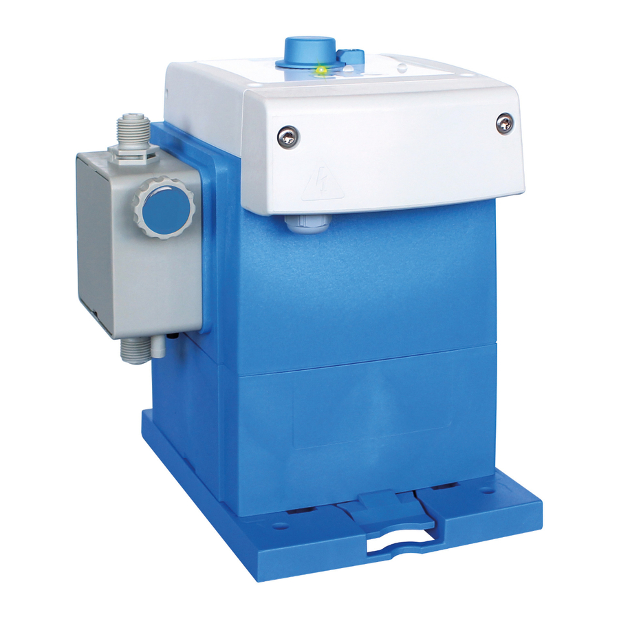
Beschreibung der Pumpe Beschreibung der Pumpe Abb. 3: Aufbau „EcoPro“ Bedienfeld Kabeldurchführung für Netzkabel / Netzanschluss Drehbares Bedienteil Sauganschluss / Saugventil Druckanschluss / Druckventil Position des Typenschildes Pumpenkopf Identifizierung der Pumpe - Typenschilder Die Pumpe ist mit einem Typenschild ausgestattet, welches die pumpenspezifischen Daten zur Identifizierung zur Verfügung stellt. -
Page 29: Anschlussbuchsen / Kabeldurchführungen
Beschreibung der Pumpe Anschlussbuchsen / Kabeldurchführungen Für den Kabelanschluss des Freigabesignals, liegt der Pumpe eine Verschraubung (M12 x 1,5) bei (Abb. 5, Pos. 3). Abb. 5: Anschlüsse „EcoPro“ Kabeldurchführung für Netzkabel / Netzanschluss Verschraubung (M12 x 1,5) Kabeldurchführung für Anschluss: Freigabesignal Zulässige Kabel-Außendurchmesser für Anschluss der EIN/Ausgänge: AD Ø... -
Page 30: Pumpenkopfvarianten
Beschreibung der Pumpe Pumpenkopfvarianten Je nach Ausführung des Pumpenkopfes und der Dosierventile, wird die Literleistung der Pumpe definiert. HINWEIS! Die Anzugsdrehmomente der Dosierkopfschrauben sind mittels eines Aufklebers auf dem entsprechenden Dosierkopf angegeben und müssen unbedingt eingehalten werden. Nach Erstinbetriebnahme und allen Wartungsarbeiten an dem Dosierkopf sind die Schrauben nach 24 Stunden Betrieb entsprechend dieser Angaben diagonal nachzuziehen um die Dichtheit des Systems zu gewährleisten. -
Page 31: Montage, Installation, Umbau Und Aufrüstung
Montage, Installation, Umbau und Aufrüstung Montage, Installation, Umbau und Aufrüstung Personal: Hersteller Mechaniker Servicepersonal Fachkraft Allgemeines und Sicherheit HINWEIS! Generelle Anweisungen zur Installation und Montage: – Die Pumpe muss an einer gut zugänglichen, frostgeschützten Stelle montiert werden. – Die in den "Technischen Daten" angegebenen Umgebungsbedingungen müssen eingehalten werden . - Page 32 Montage, Installation, Umbau und Aufrüstung Gefahren durch elektrische Energie GEFAHR! Lebensgefahr durch elektrischen Strom! Bei Berührung mit spannungsführenden Teilen besteht unmittelbare Lebensgefahr durch Stromschlag. Beschädigung der Isolation oder einzelner Bauteile kann lebensgefährlich sein. – Vor Beginn der Arbeiten, spannungsfreien Zustand herstellen und für die Dauer der Arbeiten sicherstellen.
-
Page 33: Montagevarianten
Montage, Installation, Umbau und Aufrüstung Montagevarianten Abb. 7: Standmontage (Pos.1) und Wandmontage (Pos.2) Die Pumpe kann mit der Montageplatte sowohl stehend (z.B. auf einer Konsole oder auf dem Dosierbehälter, Pos. 1), als auch an einer Wand (hängend, Pos. 2) montiert werden. Zur weiteren variablen Verwendung kann das Bedienteil der Pumpe gedreht werden, so dass variable Anschlussvarianten entstehen. -
Page 34: Standmontage- Oder Bodenmontage
Montage, Installation, Umbau und Aufrüstung 6.2.1 Standmontage- oder Bodenmontage Abb. 8: Vorbereitungen zur Standmontage Montageplatte umdrehen Für die Standmontage werden ausschließlich Halteelemente mit der Kennzahl 1 (Abb. 8, Pos. 2) verwendet. Halteelemente von hinten in die vier Öffnungen mit der Bezeichnung "table" (= Tisch / Standmontage) stecken und einrasten lassen. -
Page 35: Wandmontage
Montage, Installation, Umbau und Aufrüstung 6.2.2 Wandmontage Abb. 9: Vorbereitungen zur Wandmontage Montageplatte umdrehen. Für die Wandmontage werden Halteelemente mit der Kennzahl 2 (Abb. 9, Pos. 3) und mit der Kennzahl 1 (Abb. 9, Pos. 2) verwendet. Halteelemente (Bezeichnung: 1, Abb. 9, Pos. 2) von hinten in die zwei oberen Öffnungen mit der Bezeichnung "wall"... -
Page 36: Installation
Montage, Installation, Umbau und Aufrüstung Installation Einige der in diesem Kapitel dargestellten Grafiken sind Prinzipskizzen, die den generellen Einbau darstellen sollen. Die hier dargestellten Installationsbeispiele und Anwendungen haben funktionalen Charakter. Sie geben einen Überblick über korrekte oder zu vermeidende Installationsarten für die richtige Funktion. 6.3.1 Hydraulische Installation Personal:... -
Page 37: Installationsbeispiele
Montage, Installation, Umbau und Aufrüstung 6.3.2 Installationsbeispiele Hydraulische Installation Bei Medien, die zu Sedimentation neigen, muss das Bodensaugventil bzw. Fußventil der Saugleitung oder der Sauglanze über der zu erwartenden Schlammschicht montiert sein. Begriffsdefinition: Leerhebern Von Leerhebern, spricht man immer dann, wenn der maximale Flüssigkeitsspiegel (in diesem Fall der Entnahmebehälter) höher liegt als der tiefste Punkt der Dosierleitung. - Page 38 Montage, Installation, Umbau und Aufrüstung Installationsbeispiel 3 1 Impfventil / Dosierventil 2 Externe Freigabe 3 Magnetventil 4 Druckhalteventil Bei Dosierung in Rohrleitungen mit Unterdruck ist ein Druckhalteventil (Pos. 4) in die Dosierleitung einzubauen. Ein Druckhalte- oder Dosierventil ist kein dicht schließendes Absperrorgan. Um ein Auslaufen des Dosiermediums bei Stillstand der Pumpe zu verhindern, empfehlen wir zusätzlich den Einbau eines Magnetventils (Pos.
-
Page 39: Anschluss Von Saug- Und Druckleitungen (Dosierleitungen)
Montage, Installation, Umbau und Aufrüstung Installationsbeispiel 6 Saugleitungen müssen immer steigend zum Saugventil der Dosierpumpe verlegt werden. Installationsbeispiel 7 Eine Dosierüberwachungseinrichtung, z.B. ein Ovalradzähler (Pos. 1), oder Strömungswächter, muss in die Dosierleitung nach dem Überströmventil und vor einem Druckhalte- bzw. Dosierventil eingebaut werden. 6.3.3 Anschluss von Saug- und Druckleitungen (Dosierleitungen) VORSICHT! -
Page 40: 6.3.3.1 Schlauchanschluss Mit Stützhülse Und Klemmring
Montage, Installation, Umbau und Aufrüstung 6.3.3.1 Schlauchanschluss mit Stützhülse und Klemmring Abb. 10: Rohr- und Schlauchanschluss mit integrierter Stützhülse Rohr- oder Schlauchanschluss O-Ring Überwurfmutter Saug-, Druckventil Klemmring A1 Rohr bzw. Schlauch aufgesteckt Aufsteckhülse A2 Sollzustand nach Zusammenbau Aufschraubverschraubung B1 Ventilanschluss: Sollzustand nach Zusammenbau O-Ring (Pos. -
Page 41: 6.3.3.2 Schlauchanschluss Mit Kegelteil Und Spannteil
Montage, Installation, Umbau und Aufrüstung 6.3.3.2 Schlauchanschluss mit Kegelteil und Spannteil Abb. 11: Rohr- Schlauchanschluss mit Kegelteil Schlauch O-Ring Überwurfmutter Saug-, Druckventil Spannteil A1 Rohr bzw. Schlauch aufgesteckt Kegelteil B1 Ventilanschluss: Sollzustand nach Zusammenbau Schlauch (Pos. 1) gerade abschneiden. Überwurfmutter (Pos. 2) über Schlauch (Pos. 1) schieben. Spannteil (Pos. -
Page 42: 6.3.3.3 Rohr- Und Schlauchanschluss Mit Aufstecknippel Und Schlauchschelle
Montage, Installation, Umbau und Aufrüstung 6.3.3.3 Rohr- und Schlauchanschluss mit Aufstecknippel und Schlauchschelle Abb. 12: Rohr- und Schlauchanschluss mit Aufstecknippel und Schlauchschelle Detail/Schnitt: Einzelteildarstellung Saug-, Druckventil Schlauch Schlauchschelle Überwurfmutter A1 Rohr bzw. Schlauch aufgesteckt Kegelteil B1 Ventilanschluss: Sollzustand nach Zusammenbau O-Ring Schlauch (Pos. -
Page 43: 6.3.3.4 Rohranschluss Mit Aufschweissverbindung
Montage, Installation, Umbau und Aufrüstung 6.3.3.4 Rohranschluss mit Aufschweissverbindung Abb. 13: Rohr- und Schlauchanschluss mit Aufschraubverschraubung Aufschweißverbindung Saug-, Druckventil Rohr- oder Schlauch A1 Rohr bzw. Schlauch in der Aufschweißverbindung Überwurfmutter B1 Ventilanschluss: Sollzustand nach Zusammenbau O-Ring O-Ring (Pos. 4) in Nut von Saug-, bzw. Druckventil (Pos. 5) legen. Überwurfmutter (Pos. -
Page 44: Elektrische Installation
Montage, Installation, Umbau und Aufrüstung 6.3.4 Elektrische Installation Personal: Elektrofachkraft Für den Kabelanschluss der Impulssteuerung, liegt der Pumpe eine M 12 x 1,5 Verschraubung bei. Das Netzkabel ist werkseitig bereits montiert. Abb. 14: Elektrische Installation „EcoPro“ Beide Gehäuseschrauben lösen. Diese sind gegen herausfallen gesichert. Frontdeckel abnehmen. -
Page 45: 6.3.4.1 Klemmenbelegung - Externes Freigabesignal
Montage, Installation, Umbau und Aufrüstung 6.3.4.1 Klemmenbelegung - Externes Freigabesignal Nach Demontage des Frontdeckels, (siehe Ä Kapitel 6.3.4 „Elektrische Installation“ auf Seite 42, Abb. 14, Pos. 2), sind die Klemmen zugänglich. Entsprechend der nachfolgend beschriebenen Klemmenbelegung, können kundenseitig Anpassungen zu Steuerungseingängen vorgenommen werden. HINWEIS! Sämtliche Änderungen der Klemmenbelegung sind nur durch Fachpersonal zugelassen. - Page 46 Inbetriebnahme Inbetriebnahme Personal: Hersteller Produktionsführer Servicepersonal Fachkraft Bediener GEFAHR! – Nur zugelassenes Personal, welches im Umgang mit dem Dosiersystem vertraut ist, darf die Erstinbetriebnahme durchführen. – Die Erstinbetriebnahme ist zu protokollieren und die durchgeführten Einstellungen in das Protokoll einzutragen. – Kontrollieren Sie vor Erstinbetriebnahme den korrekten Aufbau Ihrer Ä...
-
Page 47: Inbetriebnahme
Inbetriebnahme Elektrische Gefahren GEFAHR! Gefahren durch elektrischen Strom sind mit nebenstehendem Symbol gekennzeichnet. Arbeiten an solchen Stellen dürfen ausschließlich durch ausgebildetes und autorisiertes Fachpersonal durchgeführt werden. Erstinbetriebnahme „EcoPro“ Die eingeschaltete Viskosität (hoch oder niedrig) wird beim Einschalten der Pumpe durch eine LED Anzeige dargestellt. Bedeutung der LED-Farben: LED Dosiermodus "niedrig"... -
Page 48: Autostartfunktion
Inbetriebnahme Autostartfunktion GEFAHR! Gefahr des automatischen Anlaufes der Pumpe Bereits durch Herstellen der Stromversorgung wird der automatischer Anlauf der Pumpe gestartet, ohne dass vorher noch ein Schalter/Taster betätigt werden muss. Aus Sicherheitsgründen ist die [Autostart] Funktion im Auslieferungszustand der Pumpe nicht aktiviert. VORSICHT! Der Betreiber der Pumpe ist dafür verantwortlich, das Risiko eines ungewollten Anlaufes der Pumpe nach Netzwiderkehr durch eine geeignete übergeordnete... -
Page 49: Klemmenbelegung „Externe Freigabe"" „Ecopro
Inbetriebnahme Klemmenbelegung „externe Freigabe"“ „EcoPro“ Die „EcoPro“ kann an mit einer kundenseitigen Ansteuerung, z.B. SPS Steuerung, verbunden werden (Klemmen 8 (GND) + 9 (Freigabesignal)). Abb. 17: Externe Freigabe 417102264 Rev. 5-01.2019... -
Page 50: Kalibrierung Bei Erstinbetriebnahme
Inbetriebnahme Kalibrierung bei Erstinbetriebnahme Die angegebenen Dosierleistungen bei den Dosierpumpen werden immer unter Idealbedingungen (Dosierung von Wasser bei 20 °C, kurze Saug- und Dosierleitungen, Nenn- Gegendruck, keine druckerhöhenden Ventile in der Dosierleitung) ermittelt. Da diese Bedingungen im Feld nie zutreffen, empfiehlt es sich die tatsächliche Dosiermenge der Dosierpumpe unter den vor Ort vorherrschenden Bedingungen zu kalibrieren. -
Page 51: Betrieb
Betrieb Betrieb Personal: Produktionsführer Bediener Fachkraft Ein-, Ausschalten der Pumpe Abb. 18: Ein-, Ausschalten der „EcoPro“ Drehknopf zur Hubverstellung LED - Beim Start der Pumpe: Grün (standby) Arretierung zur Fixierung des Drehknopfes LED - Dosiermodus "hoch", Farbe: Gelb blinkend LED - Alarmmeldung, Farbe: rot blinkend „AN/AUS-Taster“... -
Page 52: Einstellung Der Literleistung / Fördermenge
Betrieb Einstellung der Literleistung / Fördermenge Durch die Schrittmotortechnik kann sowohl die Saughubdauer als auch die Dosierhubdauer während des Betriebes über die Hubverstellung (Abb. 18, Pos.1) getrennt voneinander eingestellt werden. Abb. 19: Zeitliche Verteilung (t) von Saug- (s) und Dosierhub (p) bei Dosiermengeneinstellung 100, 50 und 25% Am „Drehknopf zur Hubverstellung“... -
Page 53: Gebindewechsel Durchführen - Leermeldung
Betrieb Gebindewechsel durchführen - Leermeldung Gefahren durch Chemie (Dosiermedium/Wirkstoff) GEFAHR! Verletzungsgefahr durch die angewendete Chemie (Dosiermedium) an Haut und Augen. – Vor Verwendung des Dosiermediums das beiliegende Sicherheitsdatenblatt aufmerksam lesen. – Sicherheitsbestimmungen und vorgeschriebene Schutzkleidung im Umgang mit Chemikalien sind zu beachten. –... -
Page 54: Wartung
Wartung Wartung Personal: Mechaniker Elektrofachkraft Servicepersonal Die zum Pumpentyp gehörenden Verschleiß- und Ersatzteile können anhand des Pumpenschlüssels identifiziert werden. Ä Kapitel 13.3 „Pumpenschlüssel „EcoPro“ “ Der Pumpenschlüssel ( Ä Kapitel auf Seite 75) befindet sich auf dem Typenschild ( 13.2 „Gerätekennzeichnung / Typenschild“ auf Seite 74) der Pumpe. Bevor eine Wartung durchgeführt wird, sollten die pumpenspezifischen Ä... -
Page 55: Servicestellung
Wartung Servicestellung Bevor Wartungen an der Pumpe durchgeführt werden dürfen, ist die Pumpe in den Wartungsmodus zu versetzen! Hierdurch wird die Rückstellung des Motors und der Membrane hervorgerufen, wodurch die Wartung vereinfacht wird! Die Pumpe in die Servicestellung versetzen: [AN/AUS] und [Test] Tasten gleichzeitig Drücken. -
Page 56: Wartungstabelle
Wartung Wartungstabelle Intervall Wartungsarbeit Personal 24 Stunden nach Kontrolle der Dosierkopfschrauben Mechaniker Inbetriebnahme , bzw. Die Anzugsdrehmomente der Dosierkopfschrauben sind Dosierkopfwartung auf den Pumpenköpfen mittels Aufkleber angebracht. Ä Kapitel 9.4 „Dosierventile Des weiteren sind diese im lagerichtig einbauen“ auf Seite 56 und im Kapitel Ä... -
Page 57: Austausch Von Saug- / Druckventil Und Dosierpatrone
Wartung Austausch von Saug- / Druckventil und Dosierpatrone Abb. 20: Austausch von Saug- / Druckventil und Dosierpatrone O-Ring-Schlauchanschluss Druckseite O-Ring: Saugventil-Pumpenkopf Druckventil Saugventil O-Ring: Druckventil-Pumpenkopf O-Ring-Schlauchanschluss Saugseite Dosierpatrone V3 Saug- und Druckventil mit Gabelschlüssel demontieren. Alle O-Ringe montieren. Dosierpatronen (bei Pumpenkopf mit 5 l/h) montieren (Ventilausführung V3) Neues Saug- und Druckventil lagerichtig einschrauben (Anzugsdrehmoment 2-3 Nm) HINWEIS! Anzugsdrehmomente der Saug- und Druckventile:... -
Page 58: Dosierventile Lagerichtig Einbauen
Wartung Dosierventile lagerichtig einbauen WARNUNG! Beim Einbau ist unbedingt darauf zu achten, dass die Ventile der Fließrichtung entsprechend eingebaut werden! Auf den Saug-/Druckventilen ist die Fließrichtung durch einen eingeprägten Pfeil dargestellt. HINWEIS! Die nachfolgend angegebenen Anzugsdrehmomente sind unbedingt einzuhalten um zum einen die Dichtigkeit des Systems und zum anderen die Unversehrtheit der Gewinde zu gewährleisten. -
Page 59: Austausch Der Membrane Und Des Pumpenkopfes
Wartung Austausch der Membrane und des Pumpenkopfes VORSICHT! Membrane: – Vor Wechsel der Membrane unbedingt die Pumpe in den Wartungsmodus versetzen! Ä Kapitel 9.1 „Servicestellung“ auf Seite 53 – Membrane nur handfest und ohne Werkzeug anziehen! Die Lebensdauer der Membrane ist abhängig von: –... -
Page 60: Pumpenkopfgröße 5 L/H Und 11 L/H
Wartung Pumpenkopfgröße 5 l/h und 11 l/h Abb. 21: Austausch der Membrane und des Pumpenkopfes Aufkleber: Anzugsdrehmoment Dosierkopfschrauben Membrane Abdeckplatte Zwischenplatte Dosierkopfschrauben (4 Stück) Schutzmembrane Pumpenkopf Entlüftungsschraube Beim Zusammenbau ist auf folgendes zu achten: – Neue Schutzmembrane lagerichtig einbauen. – Zwischenplatte lagerichtig einlegen. –... -
Page 61: Pumpenkopfgröße 30 L/H Und 50 L/H
Wartung Pumpenkopfgröße 30 l/h und 50 l/h Abb. 22: Austausch der Membrane und des Pumpenkopfes Aufkleber: Anzugsdrehmoment Dosierkopfschrauben 4b Zwischenplatte mit Sensor Dosierkopfschrauben (4 Stück) Schutzmembrane Pumpenkopf 6a Membranverlängerung für Zwischenplatte ohne Sensor Membrane 6b Membranverlängerung für Zwischenplatte ohne Sensor 4a Zwischenplatte ohne Sensor Beim Zusammenbau ist auf folgendes zu achten: –... -
Page 62: Pumpenkopfgröße 120 L/H
Wartung Pumpenkopfgröße 120 l/h Abb. 23: Austausch der Membrane und des Pumpenkopfes Aufkleber: Anzugsdrehmoment Dosierkopfschrauben Halteschrauben für die Adapterplatte (4 Stück) Dosierkopfschrauben (4 Stück) 6a Adapterplatte ohne Sensor Pumpenkopf 6b Adapterplatte mit Sensor Membrane Membranverlängerung Zwischenplatte. Schutzmembrane Beim Zusammenbau ist auf folgendes zu achten: –... -
Page 63: Verschleiß- Und Ersatzteile
Verschleiß- und Ersatzteile Verschleiß- und Ersatzteile HINWEIS! Sachschäden durch Verwendung von falschem Werkzeug! Durch Verwendung von falschem Werkzeug bei Montage, Wartung oder Störungsbeseitigung können Sachschäden entstehen. Nur bestimmungsgemäßes Werkzeug verwenden. VORSICHT! Eigenmächtige Umbauten oder Veränderungen sind nur nach Absprache und mit Genehmigung des Herstellers zulässig. -
Page 64: Verschleißteilset 30 L/H, 50 L/H Und 120 L/H
Verschleiß- und Ersatzteile 10.1.2 Verschleißteilset 30 l/h, 50 l/h und 120 l/h 1 x Saugventil 1 x Membrane 1 x Druckventil 1 x Schutzmembrane Pumpenleistung Bestellschlüssel für Verschleißteilset: Artikel Nr. EBS-Nr. ECO 03003S/05410M PFC 252129 auf Anfrage 30 l/h ECO 03003S/05410M PEC 252130 auf Anfrage &... - Page 65 Verschleiß- und Ersatzteile Ersatzteilbaugruppe: Cover - Steuerteil „EcoPro“ Abb. 25: Ersatzteilbaugruppe: Display Cover - Steuerteil „EcoPro“ Pos. Bezeichnung Artikel Nr. EBS-Nr. (4 x) Schraube 35 x 35 WN5451 V2A 413070100 auf Anfrage (1 x) Schraube 35 x 10 WN5451 V2A TX 413070094 auf Anfrage (1 x) Klemmteil für Drehknopf...
-
Page 66: Pumpenköpfe
Verschleiß- und Ersatzteile 10.2.2 Pumpenköpfe 10.2.2.1 Ersatzteilbaugruppe: Pumpenkopf 5 l/h Abb. 26: Ersatzteilbaugruppe: Pumpenkopf 5 l/h Pos. Bezeichnung Artikel Nr. EBS-Nr. Aufkleber Inbetriebnahme / Anzugsdrehmoment (4 Nm) 34800327 auf Anfrage Abdeckplatte PP kieselgrau 35200180 auf Anfrage Abdeckplatte PVDF natur 35200181 auf Anfrage Innensechskantschraube, M 5 x 50, DIN 912, V2A 413031127... -
Page 67: 10.2.2.2 Ersatzteilbaugruppe: Pumpenkopf 11 L/H
Verschleiß- und Ersatzteile 10.2.2.2 Ersatzteilbaugruppe: Pumpenkopf 11 l/h Abb. 27: Ersatzteilbaugruppe: Pumpenkopf 11 l/h Pos. Bezeichnung Artikel Nr. EBS-Nr. Aufkleber Inbetriebnahme / Anzugsdrehmoment (4 Nm) 34800327 auf Anfrage Abdeckplatte PP kieselgrau 35200180 auf Anfrage Abdeckplatte PVDF natur 35200181 auf Anfrage Innensechskantschraube, M 5 x 50, DIN 912, V2A, 413031127 auf Anfrage... -
Page 68: 10.2.2.3 Ersatzteilbaugruppe: Pumpenkopf 30 L/H Und 50 L/H
Verschleiß- und Ersatzteile 10.2.2.3 Ersatzteilbaugruppe: Pumpenkopf 30 l/h und 50 l/h Abb. 28: Ersatzteilbaugruppe: Pumpenkopf 30 l/h und 50 l/h Pos. Bezeichnung Artikel Nr. EBS-Nr. Aufkleber Inbetriebnahme / Anzugsdrehmoment (6 Nm) 34900291 auf Anfrage Innensechskantschraube, M 6 x 90, DIN 912, V2A 413031148 auf Anfrage Scheibe, 17 x 6.4 x 3 DIN 7349 V2A... -
Page 69: 10.2.2.4 Ersatzteilbaugruppe: Pumpenkopf 120 L/H
Verschleiß- und Ersatzteile 10.2.2.4 Ersatzteilbaugruppe: Pumpenkopf 120 l/h Abb. 29: Ersatzteilbaugruppe: Pumpenkopf 120 l/h Pos. Bezeichnung Artikel Nr. EBS-Nr. Aufkleber Inbetriebnahme / Anzugsdrehmoment (6 Nm) 34900291 auf Anfrage Innensechskantschraube, M 6 x 90, DIN 912, V2A 413031148 auf Anfrage Scheibe, 17 x 6.4 x 3 DIN 7349 V2A 413501304 auf Anfrage Pumpenkopf, 120 l/h, PP... -
Page 70: Reparatur, Umbau, Aufrüstung
Reparatur, Umbau, Aufrüstung Reparatur, Umbau, Aufrüstung Personal: Elektrofachkraft Servicepersonal Fachkraft GEFAHR! Gefahren durch elektrische Energie Arbeiten an elektrischen Bauteilen nur von zugelassenen Elektrofachkräften oder speziell geschultem Fachpersonal ausführen lassen. Lebensgefahr durch elektrischen Strom! Bei Berührung mit spannungsführenden Teilen besteht unmittelbare Lebensgefahr durch Stromschlag. -
Page 71: Reparatur, Umbau, Aufrüstung
Reparatur, Umbau, Aufrüstung 11.2 Umbau / Aufrüstung 11.2.1 Umbau - Drehen des Steuerteils Um die Pumpe den örtlichen Gegebenheiten anpassen zu können, ist es möglich das graue Steuerteil (Bedienteil / Pumpenoberteil) der Pumpe zu drehen. GEFAHR! Gefahr eines Stromschlages Achten Sie unbedingt darauf die Spannungsversorgung zu trennen und gegen wiedereinschalten zu sichern! Abb. -
Page 72: Umbau - Wechsel Von Standmontage Zur Wandmontage
Reparatur, Umbau, Aufrüstung 11.2.2 Umbau - Wechsel von Standmontage zur Wandmontage Um die Pumpe den örtlichen Gegebenheiten anpassen zu können, ist es möglich die Pumpe als Stand- oder Wandmontage zu verwenden. Abb. 31: Wechsel von Standmontage (stehend, z. B. Boden, Konsole oder Kanister) zur Wandmontage (hängend) Anschlussleitungen soweit notwendig demontieren (hydraulisch und elektrisch). -
Page 73: Aufrüstung - Von „Ecopro" Auf „Ecoadd
Reparatur, Umbau, Aufrüstung 11.2.3 Aufrüstung - Von „EcoPro“ auf „EcoAdd“ Die Pumpenversion „EcoPro“ kann durch austauschen des Steuerteils auf die „EcoAdd“ Version mit Bediendisplay und Bluetooth-Schnittstelle umgebaut, bzw. aufgerüstet werden. Abb. 32: / Aufrüstung der „EcoPro“ auf die Version „EcoAdd“ Befestigungsschrauben am Steuerteil der „EcoPro“... - Page 74 Betriebsstörungen / Fehlerbehebung Betriebsstörungen / Fehlerbehebung Personal: Produktionsführer Bediener Elektrofachkraft Mechaniker HINWEIS! Sachschäden durch Verwendung von falschem Werkzeug! Durch Verwendung von falschem Werkzeug bei Montage, Wartung oder Störungsbeseitigung können Sachschäden entstehen. Nur bestimmungsgemäßes Werkzeug verwenden. GEFAHR! – Bei allen Wartungsarbeiten ist unbedingt die vorgeschriebene Schutzkleidung (PSA) zu verwenden.
-
Page 75: Betriebsstörungen / Fehlerbehebung
Betriebsstörungen / Fehlerbehebung 12.1 Allgemeine Störungssuche und Fehlerbehebung HINWEIS! Bei einigen Fehlermeldungen ist die Pumpe immer an den Kundenservice zu senden, da nur dort in die Ebene der Steuerung eingegriffen werden kann, auf die sich diese Meldungen beziehen. Ä „Hinweis zum Einsenden von Pumpen an den Kundenservice!“ auf Seite 72 ist zu beachten! Fehlerbeschreibung Ursache... - Page 76 Technische Daten Technische Daten 13.1 Verpackung Angabe Wert Einheit Verpackungsgröße (L x B x H) 395 x 290 x 360 mm Gewicht (je nach Pumpenausführung) 3,5 - 6 Kg Bedingt durch das geringe Gewicht sind bezüglich des Transportes keine besonderen Hebezeuge erforderlich. UMWELT! Gefahr für die Umwelt durch falsche Entsorgung! Verpackungsmaterialien sind wertvolle Rohstoffe und können in vielen Fällen...
-
Page 77: Technische Daten
Technische Daten 13.3 Pumpenschlüssel „EcoPro“ Der Pumpenschlüssel besteht aus vier Gruppen: Gruppe I: Bedienteil: Ä Kapitel 13.3.1 „Pumpenschlüssel Gruppe I - "Bedienteil" [EcoPro|E|S]“ auf Seite 75 Gruppe II: Pumpenkopf: Ä Kapitel 13.3.2 „Pumpenschlüssel Gruppe II“ auf Seite 76 Gruppe III: Gehäuse / Antrieb: Ä... -
Page 78: Pumpenschlüssel Gruppe Ii
Technische Daten 13.3.2 Pumpenschlüssel Gruppe II "Pumpenkopf" [01110S|D|F|C|0|0|S] Pos. 4: „Literleistung / Gegendruck / Antrieb“ Schlüssel: Literleistung: [l/h] Druck [MPa (bar)] Antrieb Größe 00510X 0,05 - 5 1 (10) 01110S 0,11 - 11 1 (10) 03003S 0,3 - 30 0,3 (3) 05010M 0,50 - 50 1 (10) -
Page 79: Allgemeine Daten
Technische Daten 13.4 Allgemeine Daten Bezeichnung 00510X 01110S 03003M 05010M 12003M Dosiermodus [low] max. Dosierleistung [l/h] Dosiermodus [high] 33,3 min. Dosierleistung [l/h] 0,05 0,11 0,30 0,50 max. Dosiergegendruck [MPa (bar)] 0,1 (10) 0,03 (3) 0,1 (10) 0,03 (3) Dosiermodus [low] max. -
Page 80: Elektrische Daten
Technische Daten 13.5 Elektrische Daten Bezeichnung 00510X 01110S 03003M 05010M 12003M Versorgungsspannung [V / Hz] 100 - 240 ±10% / 50/60 Motorleistung [W] Schutzart IP65 Schutzklasse Niveau, externe Freigabe, Charge max. 24 V DC / 6 mA Eingänge: Impuls, Normsignal (0/4-20 mA) max. -
Page 81: Werkstoffe
Technische Daten 13.7 Werkstoffe Gehäuse: PPO (Noryl) Dosierkopf: PP, wahlweise PVDF, nichtrostender Stahl 1.4571 Membrane: PTFE - EPDM-Verbundmembrane Dichtungen: FKM oder EPDM, wahlweise PTFE oder FFPM (Kalrez) Ventilkugeln: Keramik, wahlweise PTFE oder nichtrostender Stahl 1.4401 Ventilfedern: Hastelloy C4 Farbe: Blau RAL 5007 Sonderausführungen sind auf Anfrage verfügbar. -
Page 82: Dosierpumpe Ecopro
Technische Daten 13.8.2 Dosierpumpe EcoPro Abb. 35: Abmessungen „EcoPro“ 13.9 Dosierleistungsdiagramme / Förderleistungen 13.9.1 Förderleistung: 5 l/h, Dosiergegendruck: 1 MPa (10 bar) DV Dosiervolumen [l/h] DP Dosiergegendruck [bar] 417102264 Rev. 5-01.2019... -
Page 83: Förderleistung: 11 L/H, Dosiergegendruck: 1 Mpa (10 Bar)
Technische Daten 13.9.2 Förderleistung: 11 l/h, Dosiergegendruck: 1 MPa (10 bar) DV Dosiervolumen [l/h] DP Dosiergegendruck [bar] 13.9.3 Förderleistung: 30 l/h, Dosiergegendruck: 0,3 MPa (3 bar) DV Dosiervolumen [l/h] DP Dosiergegendruck [bar] 417102264 Rev. 5-01.2019... -
Page 84: Förderleistung: 50 L/H, Dosiergegendruck: 1 Mpa (10 Bar)
Technische Daten 13.9.4 Förderleistung: 50 l/h, Dosiergegendruck: 1 MPa (10 bar) DV Dosiervolumen [l/h] DP Dosiergegendruck [bar] 13.9.5 Förderleistung 120 l/h, Dosiergegendruck: 0,3 MPa (3 bar) DV Dosiervolumen [l/h] DP Dosiergegendruck [bar] 417102264 Rev. 5-01.2019... -
Page 85: Außerbetrieb Setzen / Demontage / Umweltschutz
Außerbetrieb setzen / Demontage / Umweltschutz Außerbetrieb setzen / Demontage / Umweltschutz Personal: Hersteller Produktionsführer Bediener Elektrofachkraft Mechaniker GEFAHR! Verletzungsgefahr durch außer Acht lassen der vorgeschriebenen Schutzausrüstung (PSA)! Beachten Sie bei allen Demontagearbeiten die Verwendung der laut Produktdatenblatt vorgeschriebenen PSA. 14.1 Außer Betrieb setzen GEFAHR! -
Page 86: Demontage
Außerbetrieb setzen / Demontage / Umweltschutz 14.2 Demontage GEFAHR! Die Demontage darf nur von Fachpersonal unter Verwendung der PSA durchgeführt werden. Achten Sie darauf, dass vor Beginn der Demontagearbeiten die komplette Stromversorgung getrennt wurde. Bei Kontakt mit spannungsführenden Bauteilen besteht Lebensgefahr. Eingeschaltete elektrische Bauteile können unkontrollierte Bewegungen ausführen und zu schwersten Verletzungen führen. -
Page 87: Entsorgung Und Umweltschutz
Außerbetrieb setzen / Demontage / Umweltschutz 14.3 Entsorgung und Umweltschutz UMWELT! Gefahr für die Umwelt durch falsche Entsorgung! Durch falsche Entsorgung können Gefahren für die Umwelt entstehen. – Elektroschrott, Elektronikkomponenten, Schmier- und andere Hilfsstoffe von zugelassenen Fachbetrieben entsorgen lassen. – Im Zweifel Auskunft zur umweltgerechten Entsorgung bei der örtlichen Kommunalbehörde oder speziellen Entsorgungsfachbetrieben einholen. -
Page 88: Ce-Erklärung / Konformitätserklärung
„Konformitätserklärung / CE-Erklärung“ ändert. Die aktuellste „Konformitätserklärung / CE-Erklärung“ wird daher im Internet veröffentlicht: Zum Download der Anleitungen nutzen Sie den unten aufgeführten Link oder scannen Sie den QR-Code ein. http://www.ecolab-engineering.de/fileadmin/download/ bedienungsanleitungen/ce-konformitaetserklaerung/CE/ CE_EcoPro_EcoAdd.pdf Abb. 36: CE-Erklärung / Konformitätserklärung 417102264 Rev. 5-01.2019... - Page 89 Index Index Abmessungen ..... . 79, 80 Fehlgebrauch ......12 Android App Download .
- Page 90 Index IOS (Apple) App Download ......6 Service Kontakt ......11 Servicekontakt Kennzeichnung Hersteller .
- Page 91 Index Typenschild ......74 Verpackungsgröße der Lieferung ......8 Verweise Umweltschutz Darstellungsweise .
- Page 92 / revision: Letze Änderung: 08.01.2019 last changing: Copyright Ecolab Engineering GmbH, 2019 Alle Rechte vorbehalten All rights reserved Nachdruck, auch auszugsweise, nur mit Genehmigung der Firma Ecolab Engineering GmbH Reproduction, also in part, only with permission of Ecolab Engineering GmbH...
- Page 93 Operating instructions EcoPro Ecolab Dynamic Pump EcoPro 417102264 Rev. 5-01.2019 08.01.2019 ENGLISH...
- Page 94 Table of contents Table of contents General information....................5 1.1 Information on User Manual................5 1.2 Availability and updating of the operating instructions........5 1.3 Call up operating instructions with smartphone..........6 1.4 Article numbers / EBS-Article numbers.............. 6 1.5 Copyright......................6 1.6 Symbols, highlighting and enumerations............
- Page 95 Table of contents 6.3.3.1 Pipe and hose connection with integrated support sleeve......38 6.3.3.2 Pipe and hose connection with tapered part..........39 6.3.3.3 Pipe and hose connection with attachment nipple and hose clamp... 40 6.3.3.4 Pipe and hose connection with female coupling......... 41 6.3.4 Electrical Installation..................
- Page 96 Table of contents 12.2 LED - fault messages ..................73 Technical specifications..................74 13.1 Packaging....................... 74 13.2 Equipment marking / Type plate..............74 13.3 ‘EcoPro’ pump key..................75 13.3.1 Pump key group I..................75 13.3.2 Pump key group II..................76 13.3.3 Pump key group III..................
-
Page 97: General Information
All operating instructions are kept up to date at all times and freely available online for download. To download the instructions with a PC, tablet or Smartphone, use the links below or scan the QR code. Download of the operating instructions ‘EcoPro’ (Article No. 417102264): https://www.ecolab-engineering.de/fileadmin/download/ bedienungsanleitungen/dosiertechnik/Dosierpumpen/ 417102264-EcoPro.pdf 417102264 Rev. 5-01.2019... -
Page 98: Call Up Operating Instructions With Smartphone
"Google Play" app This app can be used to access the app store for the Android system. This can be searched for and installed by entering the app name "Ecolab DocuAPP" smartphones have the "APP Store" app This app can be used to access the app store for the Apple IOS system. -
Page 99: Tips And Recommendations
General information WARNING! This combination of symbol and signal word indicates a potentially dangerous situation which could result in serious or fatal injury if not avoided. CAUTION! This combination of symbol and signal word indicates a potentially dangerous situation that could lead to minor or slight injuries if not avoided. NOTICE! This combination of symbol and signal word indicates a potentially dangerous situation that could lead to material damage if not avoided. -
Page 100: Transport
General information Further markings The following markings are used in this manual to highlight operating instructions, results, collections, references and other elements: Marking Explanation 1., 2., 3..Step by step operating instructions ð Results of the operating steps References to sections of this manual and related documents Collections in no set order [Button] Controls (e.g. -
Page 101: Transport Inspection
General information Transport inspection NOTICE! Check the delivery for completeness and any transport damage. In case of visible damage, proceed as follows: Do not accept the delivery or accept provisionally. Note down the extent of damage in the transport documents or on the delivery slip. Lodging a complaint. -
Page 102: Storage
General information Symbols on the packaging Symbol Name Description The individual package must always be transported, handled and stored in such a way that the arrows point upwards at all times. Rollers, flaps, heavy tipping or edges and other forms of handling must be avoided. -
Page 103: Warranty
The general warranty and service conditions of the manufacturer also apply. 1.12 Manufacturer's service and contact address Ecolab Engineering GmbH Raiffeisenstraße 7 D-83313 Siegsdorf, Germany Telephone (+49) 86 62 / 61 0 Fax (+49) 86 62 / 61 166 Email: engineering-mailbox@ecolab.com... -
Page 104: Safety
Safety Safety General Safety DANGER! If you assume that safe operation is no longer possible the pump must be put out of service immediately and be secured against unauthorized use. This is the case if: – is visibly damaged – appears no longer functional –... -
Page 105: Reasonable Foreseeable Incorrect Use
Safety WARNING! Danger of improper use! Improper use may result in dangerous situations: – Never use metering media other than the specified product. – Never change the product metering guidelines beyond the tolerable range. – Do not use in potentially explosive areas. –... -
Page 106: Lifetime
Safety Lifetime In relation to the dependence of the adequate maintenance protocols the life time is 2 years (visual and functional testing, replacement of wearing parts, etc.) Afterwards a revision is necessary, in some cases also a subsequent general overhaul by the manufacturer. -
Page 107: Qualified Electrician
Safety Production supervisor The production supervisor is capable of performing the work assigned to them because of their technical training, knowledge and experience, as well as awareness of the relevant standards and regulations; they are able to autonomously identify and prevent potential risks. -
Page 108: Indications Of Risks
Safety WARNING! Protective work clothing In the event of works in areas, which are identified with an adjacent symbol, appropriate protective clothing is to be worn. Protective work clothing is close- fitting clothing with low resistance to tearing, close-fitting sleeves and no protruding parts. - Page 109 Safety Risk due to electrical energy DANGER! Risk of fatal injury from electric current! Contact with live parts represents immediate danger to life due to electrocution. Damage to the insulation or individual components can be life-threatening. – Before starting work, create a de-energised state and ensure this state for the duration of the work.
- Page 110 Safety Unauthorised access DANGER! Unauthorised access The owner must ensure that unauthorised personnel are prevented from accessing the operating area. Chemical hazards (dosing medium/active substance) DANGER! Risk of injury to the skin and eyes caused by the chemical used (dosing medium). –...
-
Page 111: Environmental Protection Measures
If you are not sure you have a current version of the safety data sheet, please contact your Ecolab consultant. He/she will be glad to assist you in ensuring that the measures for safeguarding health in the workplace are guaranteed. -
Page 112: Obligations Of The Operator
Safety Obligations of the operator In the EEA (European Economic Area), national implementation of the Directive (89/391/EEC) and corresponding individual directives, in particular the Directive (2009/104/EC) concerning the minimum safety and health requirements for the use of work equipment by workers at work, as amended, are to be observed and adhered to. - Page 113 Safety DANGER! Damage and injuries may occur if installation, maintenance or repair work is carried out incorrectly. – All installation, maintenance and repair work must only be performed by authorised and trained specialist personnel in accordance with the applicable local regulations. –...
-
Page 114: Package Content
– PEC = pump head: PP, O-rings: EPDM, valve ball: Ceramic – DFC = pump head: PVDF, O-rings: FKM, valve ball: Ceramic – DEC = pump head: PVDF, O-rings: EPDM, valve ball: Ceramic Ecolab Dynamic Pump ‘EcoPro’ Capacity Description Item no. - Page 115 Package content AND: Display Description Item no. EBS No. Mounting plate with retainer clips 35200103 on request (6 off) and attachment set Short operating manual 417102268 on request ‘EcoPro’ and ‘’ ‘EcoAdd’ 417102264 Rev. 5-01.2019...
-
Page 116: Functional Description
Functional description Functional description ‘EcoPro’ metering pumps are diaphragm metering pumps powered by an electric motor to transport clean, non-abrasive dosing media. The stepper motor technology used here means that both the suction stroke duration and metering stroke duration can be adjusted separately. This results in a variety of benefits such as a large setting range, virtually continuous and low-pulsation metering, and even the option to respond to high viscosity or challenging intake conditions. -
Page 117: Features - 'Ecopro
Functional description The pumps consist of three main assemblies: Housing with driver unit Pump head Control unit. The construction has been chosen so that it is very easy to change between the ‘EcoPro’ and ‘EcoAdd’ ( Ä Chapter 11.2.3 ‘Upgrading - From ‘EcoPro’ to ‘EcoAdd’ ’ on page 71). -
Page 118: Description Of The Pump
Description of the pump Description of the pump Fig. 3: Construction ‘EcoPro’ Operator panel Mains cable bushing / mains power supply Rotary operating device Suction connection / suction valve Pressure connection / pressure valve Position of type plate Pump head Identification of the pump - Type plates The pump is equipped with a type plate which provides the pump-specific data for identification. -
Page 119: Connection Sockets / Cable Bushings
Description of the pump Connection sockets / cable bushings A screw coupling (M12 x 1.5) is supplied with the pump (Fig. 5, 3) for the cable connection of the enable signal. Fig. 5: EcoPro connections ‘’ Mains cable bushing / Mains connection Screw coupling (M12 x 1.5) Cable bushing for connection: Enable signal Permissible external diameters for connecting the inputs/outputs:... -
Page 120: Pump Head Variants
Description of the pump Pump head variants The litre capacity of the pump is defined depending on the design of the pump head and of the metering valves. NOTICE! Tightening torques of the metering head screws are given on an adhesive label on the corresponding metering head and must always be observed. -
Page 121: Assembly, Installation, Modification And Upgrades
Assembly, installation, modification and upgrades Assembly, installation, modification and upgrades Personnel: Manufacturer Mechanic Service personnel Specialist General information and safety NOTICE! General instructions for installation and assembly: – The pump must be installed at an easily accessible, frost-protected location. – The ambient conditions given in the "Technical data" must be observed. –... - Page 122 Assembly, installation, modification and upgrades Risk due to electrical energy DANGER! Risk of fatal injury from electric current! Contact with live parts represents immediate danger to life due to electrocution. Damage to the insulation or individual components can be life-threatening. –...
-
Page 123: Assembly Variants
Assembly, installation, modification and upgrades Assembly variants Fig. 7: Stand mounting (pos. 1) and wall mounting (pos. 2) The pump can be mounted using the mounting plate both upright (e.g. on a bracket or on the metering container, pos. 1), and on a wall (suspended, pos. 2). For further variable use, the operating part of the pump can be turned to produce variable connection variants. -
Page 124: Stand Mounting Or Floor Mounting
Assembly, installation, modification and upgrades 6.2.1 Stand mounting or floor mounting Fig. 8: Preparations for stand mounting Turn mounting plate over Only use fastening elements with the code 1 (Fig. 8, 2) for stand mounting. Insert fastening elements from the rear into the four openings marked "table" (= stand mounting) and secure them. -
Page 125: Wall Mounting
Assembly, installation, modification and upgrades 6.2.2 Wall mounting Fig. 9: Preparations for wall mounting Turn mounting plate over. Use fastening elements with the code 2 (Fig. 9, 3) and the code 1 (Fig. 9, 2) for wall mounting. Insert fastening elements (labelled: 1, Fig. 9, 2) into the two upper openings marked "wall"... -
Page 126: Installation
Assembly, installation, modification and upgrades Installation Some of the graphics shown in this chapter are schematic diagrams which are intended to represent the general installation. The installation examples and applications shown here are of a functional nature. They provide an overview of correct forms of installation, or approaches to be avoided, in order to ensure that it works properly. -
Page 127: Installation Examples
Assembly, installation, modification and upgrades 6.3.2 Installation examples Hydraulic installation With media that tend towards sedimentation, the base suction valve or the foot valve of the suction line or suction lance must be mounted above the expected sludge layer. Term definition Siphoning Siphoning refers to the maximum fluid level (in this case the supply container) being higher than the lowest point in the metering line. - Page 128 Assembly, installation, modification and upgrades Installation example 3 1 Injection valve / metering valve 2 External release 3 Solenoid valve 4 Pressure control valve When metering in pipes with a vacuum, a pressure control valve (pos. 4) is to be installed in the metering line. A pressure-retention valve or metering valve is not a shut-off device which is absolutely tight sealing.
-
Page 129: Connection Of The Suction And Pressure Lines (Dosing Lines)
Assembly, installation, modification and upgrades Installation example 6 The suction line must always be installed sloping upwards towards the metering pump. Installation example 7 A metering monitoring instrument, such as an oval gear motor (pos. 1), or flow monitor, must be installed into the metering line downstream of the overflow valve and upstream of a pressure control valve or metering valve. -
Page 130: 6.3.3.1 Pipe And Hose Connection With Integrated Support Sleeve
Assembly, installation, modification and upgrades 6.3.3.1 Pipe and hose connection with integrated support sleeve Fig. 10: Pipe and hose connection with integrated support sleeve Pipe or hose connection O-ring Union nut Suction valve, pressure valve Clamping ring A1 Pipe or hose attached Slip-on bushing A2 Target state after assembly Female connector... -
Page 131: 6.3.3.2 Pipe And Hose Connection With Tapered Part
Assembly, installation, modification and upgrades 6.3.3.2 Pipe and hose connection with tapered part Fig. 11: Pipe/hose connection with tapered part Hose O-ring Union nut Suction valve, pressure valve Clamping piece A1 Pipe or hose attached Tapered part B1 Valve connection: Target state after assembly Cut hose (1) straight. -
Page 132: 6.3.3.3 Pipe And Hose Connection With Attachment Nipple And Hose Clamp
Assembly, installation, modification and upgrades 6.3.3.3 Pipe and hose connection with attachment nipple and hose clamp Fig. 12: Pipe and hose connection with attachment nipple and hose clamp Detail/Section: Illustration of individual part Suction valve, pressure valve Hose Hose clamp Union nut A1 Pipe or hose attached Tapered part... -
Page 133: 6.3.3.4 Pipe And Hose Connection With Female Coupling
Assembly, installation, modification and upgrades 6.3.3.4 Pipe and hose connection with female coupling Fig. 13: Pipe and hose connection with female coupling Weld-on connection Suction valve, pressure valve Pipe or hose A1 Pipe or hose in the weld-on connection Union nut B1 Valve connection: Target state after assembly O-ring Place the O-ring (4) in the groove of the suction or pressure valve (5). -
Page 134: Electrical Installation
Assembly, installation, modification and upgrades 6.3.4 Electrical Installation Personnel: Qualified electrician To allow the connection of a cable for pulse control, a M 12 x 1.5 screw coupling is included with the pump. The mains cable is already installed at the factory. Fig. -
Page 135: 6.3.4.1 Terminal Assignment - External Enable Signal
Assembly, installation, modification and upgrades 6.3.4.1 Terminal assignment - External enable signal The terminals are accessible after dismantling the front cover, (see Ä Chapter 6.3.4 ‘Electrical Installation’ on page 42, Fig. 14, 2). In accordance with the terminal assignment given below, modifications can be made to control inputs at the customer's site. - Page 136 Start-up Start-up Personnel: Manufacturer Production supervisor Service personnel Specialist Operator DANGER! – Initial start-up may only be performed by authorised personnel with experience of metering system operation. – Initial start-up must be documented and the settings made recorded in the log.
-
Page 137: Start-Up
Start-up Electrical dangers DANGER! Electrical hazards are marked by the symbol opposite. Work in these areas may only be carried out by trained personnel with the appropriate authorisation. Initial start-up of the ‘EcoPro’ The enabled viscosity (high or low) is indicated by an LED display when the pump is switched on. -
Page 138: Auto Start Function
Start-up Auto start function DANGER! Danger of automatic start of the pump The the pump is automatically started by connecting the power supply already, without having to press a switch / button before. For security reasons the [auto start] function is not activated when the pump is delivered. -
Page 139: Terminal Assignment 'External Enable"' 'Ecopro
Start-up Terminal assignment ‘external enable"’ ‘EcoPro’ The ‘EcoPro’ can be connected to a customer control unit, such as a PLC controller (terminals 8 (GND) and 9 (enable signal)). Fig. 17: External enable 417102264 Rev. 5-01.2019... -
Page 140: Calibration On Initial Start-Up
Start-up Calibration on initial start-up The specified metering capacities in metering pumps are always determined under ideal conditions (metering of water at 20 °C, short suction and metering pipes, rated back- pressure, no pressure-boosting valves in the metering line). As these conditions never occur in the field, you are advised to calibrate the actual metering rate of the metering pump under the prevailing conditions on-site. -
Page 141: Operation
Operation Operation Personnel: Production supervisor Operator Specialist Switching the pump on and off Fig. 18: Switching the EcoPro on/off ‘’ Rotary button for stroke adjustment LED - When the pump is started: green (standby) Locking mechanism for fixing the rotary button in place LED - Dosing mode "high", colour: flashing yellow LED - Alarm signal, colour: red flashing ‘ON/OFF button’... -
Page 142: Setting Of The Capacity / Flow Rate
Operation Setting of the capacity / flow rate The stepper motor technology means that both the suction stroke duration and metering stroke duration can be set separately during operation via the stroke adjustment (Fig. 18, pos. 1). Fig. 19: Time distribution (t) of the suction (s) and metering stroke (p) at a metering rate setting of 100, 50 and 25% Use the ‘rotary button for stroke adjustment’... -
Page 143: Changing A Container - Empty Signal
Operation Changing a container - Empty signal Chemical hazards (dosing medium/active substance) DANGER! Risk of injury to the skin and eyes caused by the chemical used (dosing medium). – Read the enclosed safety data sheet carefully before using the dosing medium. - Page 144 Maintenance Maintenance Personnel: Mechanic Qualified electrician Service personnel The wearing and spare parts belonging to the pump type can be identified on the basis of the pump key. Ä Chapter 13.3 ‘ ‘EcoPro’ pump key’ on page 75) can be The pump key ( Ä...
-
Page 145: Maintenance
Maintenance Service position Before maintenance work is permitted to be performed on the pump, the pump should be changed to maintenance mode! The causes the motor and the diaphragm to be reset, simplifying the maintenance work! Putting the pump in the service position: [Pressing the ON/OFF] and [test] buttons simultaneously. -
Page 146: Maintenance Table
Maintenance Maintenance table Interval Maintenance work Personnel 24 hours after Checking the metering head screws Mechanic commissioning or The tightening torques of the metering head screws are metering head attached to the pump heads using adhesive labels. In servicing Ä Chapter 9.4 ‘Installing addition, these are specified in the the dosing valve in the correct position’... -
Page 147: Replace The Suction / Pressure Valve And Metering Cartridge
Maintenance Replace the suction / pressure valve and metering cartridge Fig. 20: Replace the suction / pressure valve and metering cartridge O-ring, hose connection, pressure side O-ring: Pump head suction valve Pressure valve Suction valve O-ring: Pump head pressure valve O-ring, hose connection, suction-side V3 metering cartridge Remove suction and pressure valve using an open spanner. -
Page 148: Installing The Dosing Valve In The Correct Position
Maintenance Installing the dosing valve in the correct position WARNING! When installing the valves, ensure that the flow direction is correct. The direction of flow is marked by an impressed arrow on the suction/ pressure valves. NOTICE! It is essential that the tightening torques given below are observed, firstly to ensure the leak-tightness of the system and secondly to ensure the integrity of the thread. -
Page 149: Replacing The Pump Head And Diaphragm
Maintenance Replacing the pump head and diaphragm CAUTION! Diaphragm: – Before changing the diaphragm, it is essential to change the pump to servicing mode. Ä Chapter 9.1 ‘Service position’ on page 53 – Only tighten diaphragms by hand and do not use any tools! The service life of the diaphragm depends on the following: –... -
Page 150: Pump Head Size 5 L/H And 11 L/H
Maintenance Pump head size 5 l/h and 11 l/h Fig. 21: Replacing the pump head and diaphragm Adhesive label: Tightening torque of metering head Diaphragm screws Intermediate plate Cover plate Protective diaphragms Metering head screws (4 off) Vent screw Pump head Note the following points during assembly: –... -
Page 151: Pump Head Size 30 L/H And 50 L/H
Maintenance Pump head size 30 l/h and 50 l/h Fig. 22: Replacing the pump head and diaphragm Adhesive label: Tightening torque of metering head 4b Intermediate plate with sensor screws Protective diaphragms Metering head screws (4 off) 6a Diaphragm extension for intermediate plate without Pump head sensor Diaphragm... -
Page 152: Pump Head Size 120 L/H
Maintenance Pump head size 120 l/h Fig. 23: Replacing the pump head and diaphragm Adhesive label: Tightening torque of metering head Retaining bolts for the adapter plate (x4) screws 6a Adapter plate without sensor Metering head screws (4 off) 6b Adapter plate with sensor Pump head Diaphragm extension Diaphragm... -
Page 153: Consumables And Spare Parts
Consumables and spare parts Consumables and spare parts NOTICE! Material damage by using incorrect tools! Material damage may arise by using incorrect tools during assembly, maintenance or troubleshooting. Only use the correct tools. CAUTION! Independent conversions or changes are only permissible following consultation and with the approval of the manufacturer. -
Page 154: Set Of Wearing Parts 30 L/H, 50 L/H And 120 L/H
Consumables and spare parts 10.1.2 Set of wearing parts 30 l/h, 50 l/h and 120 l/h 1 x suction valve 1 x diaphragm 1 x Pressure valve 1 x protective diaphragm Pump capacity Order code for wearing parts set: Article no. EBS-no. - Page 155 Consumables and spare parts Replacement part module: Cover - ‘EcoPro control part’ Fig. 25: Replacement part module: Display Cover - EcoAdd control unit ‘’ Pos. Designation Article No. EBS No. (4 x) screw, 35 x 30 WN5451 V2A 413070100 On request (1 x) screw, 35 x 10 WN5451 V2A TX 413070094 On request...
-
Page 156: Pump Heads
Consumables and spare parts 10.2.2 Pump heads 10.2.2.1 Replacement part module: Pump head 5 l/h Fig. 26: Replacement part module: Pump head 5 l/h Pos. Designation Article No. EBS No. Adhesive label for commissioning / tightening torque (4 Nm) 34800327 On request Cover plate PP pebble grey 35200180... -
Page 157: 10.2.2.2 Replacement Part Module: Pump Head 11 L/H
Consumables and spare parts 10.2.2.2 Replacement part module: Pump head 11 l/h Fig. 27: Replacement part module: Pump head 11 l/h Pos. Designation Article No. EBS No. Adhesive label for commissioning / tightening torque (4 Nm) 34800327 On request Cover plate PP pebble grey 35200180 On request Cover plate PVDF natural... -
Page 158: 10.2.2.3 Replacement Part Module: Pump Head 30 L/H And 50 L/H
Consumables and spare parts 10.2.2.3 Replacement part module: Pump head 30 l/h and 50 l/h Fig. 28: Replacement part module: Pump head 30 l/h and 50 l/h Pos. Designation Article No. EBS No. Adhesive label for commissioning / tightening torque (6 Nm) 34900291 On request Hexagon socket screw, M 6 x 90, DIN 912, V2A... -
Page 159: 10.2.2.4 Replacement Part Module: Pump Head 120 L/H
Consumables and spare parts 10.2.2.4 Replacement part module: Pump head 120 l/h Fig. 29: Replacement part module: Pump head 120 l/h Pos. Designation Article No. EBS No. Adhesive label for commissioning / tightening torque (6 Nm) 34900291 On request Hexagon socket screw, M 6 x 90, DIN 912, V2A 413031148 On request Washer, 17 x 6.4 x 3 DIN 7349 V2A... -
Page 160: Repair, Conversion, Upgrade
Repair, conversion, upgrade Repair, conversion, upgrade Personnel: Qualified electrician Service personnel Specialist DANGER! Risk due to electrical energy Work on electrical components should only be performed by qualified electrical engineers or specially trained expert personnel. Risk of fatal injury from electric current! Contact with live parts represents immediate danger to life due to electrocution. -
Page 161: Modification/Upgrade
Repair, conversion, upgrade 11.2 Modification/upgrade 11.2.1 Modification - turning the pump head To allow the pump to be adjusted to the site conditions, it is possible to turn the grey control unit (operating unit/upper part of the pump). DANGER! Risk of electric shock Pay attention to disconnect the power supply immediately and to secure against accidental switch-on! Fig. -
Page 162: Modification - Change From Stand Mounting To Wall Mounting
Repair, conversion, upgrade 11.2.2 Modification - change from stand mounting to wall mounting To allow the pump to be adjusted to the site conditions, you can use the pump in either stand-mounted or wall-mounted form. Fig. 31: Changing stand mounting (upright, e.g., floor, bracket or canister) for wall mounting (suspended) If necessary, dismantle the connecting lines (hydraulic and electric). -
Page 163: Upgrading - From 'Ecopro' To 'Ecoadd
Repair, conversion, upgrade 11.2.3 Upgrading - From ‘EcoPro’ to ‘EcoAdd’ The ‘EcoPro’ version of the pump can be converted or upgraded to the ‘EcoAdd’ version with an operating display and Bluetooth interface by replacing the control unit. Fig. 32: / Upgrading the ‘EcoPro’ to the ‘EcoAdd version’ Undo the fastening screws on the control unit of the ‘EcoPro’... -
Page 164: Operational Malfunctions / Troubleshooting
Operational malfunctions / troubleshooting Operational malfunctions / troubleshooting Personnel: Production supervisor Operator Qualified electrician Mechanic NOTICE! Damage caused by using incorrect tools! Damage may occur as a result of using incorrect tools during assembly, maintenance or troubleshooting. Only use the correct tools. DANGER! –... -
Page 165: General Troubleshooting And Fault Rectification
Operational malfunctions / troubleshooting 12.1 General troubleshooting and fault rectification NOTICE! With some error messages the pump should always be sent to the customer service department as it is only possible to access the level of the control to which these messages relate. Ä... -
Page 166: Technical Specifications
Technical specifications Technical specifications 13.1 Packaging Data Value Unit Packaging size (L x W x H) 395 x 290 x 360 mm Weight (depending on pump design) 3,5 - 6 Kg Due to the low weight, no special lifting gear is required during transport. ENVIRONMENT! Risk of environmental damage due to incorrect disposal! Packaging materials are valuable raw materials and can, in many cases, be... -
Page 167: Ecopro' Pump Key
Technical specifications 13.3 ‘EcoPro’ pump key The pump key comprises four groups: Group I: Control unit: Ä Chapter 13.3.1 ‘Pump key group I’ on page 75 Group II: Pump head: Ä Chapter 13.3.2 ‘Pump key group II’ on page 76 Group III: Housing/driver unit: Ä... -
Page 168: Pump Key Group Ii
Technical specifications 13.3.2 Pump key group II "Pump head" [01110S|D|F|C|0|0|S] Pos. 4: ‘Capacity in L/back-pressure/driver unit’ Key: Capacity in L: [l/h] Pressure [MPa (bar)] Size of driver unit 00510X 0,05 - 5 1 (10) 01110S 0,11 - 11 1 (10) 03003S 0,3 - 30 0,3 (3) -
Page 169: General Data
Technical specifications 13.4 General data Type Type Type Type Type Name 00510X 01110S 03003M 05010M 12003M Metering mode [low] Max. metering capacity [l/h] Metering mode 33.3 [high] Min. metering capacity [l/h] 0.05 0.11 0.30 0.50 Max. metering back-pressure [MPa (bar)] 0.1 (10) 0.03 (3) 0.1 (10) -
Page 170: Electrical Data
Technical specifications 13.5 Electrical data Type Type Type Type Type Name 00510X 01110S 03003M 05010M 12003M Supply voltage [V / Hz] 100 - 240 ±10% / 50/60 Motor power [W] Degree of protection IP65 Appliance class Level, external release, batch max. -
Page 171: Materials
Technical specifications 13.7 Materials Enclosure: PPO (Noryl) Metering head: PP, optionally PVDF, stainless steel 1.4571 Diaphragm: PTFE - EPDM composite diaphragm Seals: FKM or EPDM, either PTFE or FFPM (Kalrez) Valve balls: Ceramic, either PTFE or stainless steel 1.4401 Valve springs: Hastelloy C4 Colour: Blue RAL 5007... -
Page 172: Ecopro Metering Pump
Technical specifications 13.8.2 EcoPro metering pump Fig. 35: Dimensions ‘EcoPro’ 13.9 Metering capacity diagrams/flow rates 13.9.1 Flow rate: 5 l/h, metering back-pressure: 1 MPa (10 bar) DV Metering volume [l/h] DP Metering back-pressure [bar] 417102264 Rev. 5-01.2019... -
Page 173: Flow Rate: 11 L/H, Metering Back-Pressure: 1 Mpa (10 Bar)
Technical specifications 13.9.2 Flow rate: 11 l/h, metering back-pressure: 1 MPa (10 bar) DV Metering volume [l/h] DP Metering back-pressure [bar] 13.9.3 Flow rate: 30 l/h, metering back-pressure: 0.3 MPa (3 bar) DV Metering volume [l/h] DP Metering back-pressure [bar] 417102264 Rev. -
Page 174: Flow Rate: 50 L/H, Metering Back-Pressure: 1 Mpa (10 Bar)
Technical specifications 13.9.4 Flow rate: 50 l/h, metering back-pressure: 1 MPa (10 bar) DV Metering volume [l/h] DP Metering back-pressure [bar] 13.9.5 Flow rate 120 l/h, metering back-pressure: 0.3 MPa (3 bar) DV Metering volume [l/h] DP Metering back-pressure [bar] 417102264 Rev. -
Page 175: Decommissioning / Dismantling / Environmental Protection
Decommissioning / dismantling / environmental protection Decommissioning / dismantling / environmental protection Personnel: Manufacturer Production supervisor Operator Qualified electrician Mechanic DANGER! Risk of injury due to the disregard of the specified personal protective equipment (PPE)! For all disassembly work, please respect the use of the PSA which is specified on the product data sheet. -
Page 176: Dismantling
Decommissioning / dismantling / environmental protection 14.2 Dismantling DANGER! Dismantling may only be carried out by skilled personnel using PPE. Before commencing dismantling, ensure that the device has been fully isolated from the power supply. Contact with live components can be fatal. Activated electrical components can make uncontrolled movements and lead to serious injury. -
Page 177: Disposal And Environmental Protection
Decommissioning / dismantling / environmental protection 14.3 Disposal and environmental protection ENVIRONMENT! Risk of environmental damage due to incorrect disposal! Incorrect disposal can be a threat to the environment. – Electrical scrap, electronic components, lubricants and other operating fluids must be disposed of by approved waste disposal service providers –... -
Page 178: Ec Declaration/Declaration Of Conformity
Declaration ’ may change. The latest ‘Declaration of Conformity / CE Declaration’ will therefore be published on the internet: To download the instructions, please use the link below or scan the QR code. http://www.ecolab-engineering.de/fileadmin/download/ bedienungsanleitungen/ce-konformitaetserklaerung/CE/ CE_EcoPro_EcoAdd.pdf Fig. 36: EC Declaration/Declaration of Conformity... - Page 179 Index Index Android App Hydraulic installation Download ......6 Installation example 1 ....35 Installation example 2 .
- Page 180 Index Mounting plate Results of the operating steps Use in pump series ....79 Representation method ....8 Multi-function valve .
- Page 181 Index on the packaging ..... 10 Type plate ......74 Technical specifications Use .
- Page 182 / revision: Letze Änderung: 08.01.2019 last changing: Copyright Ecolab Engineering GmbH, 2019 Alle Rechte vorbehalten All rights reserved Nachdruck, auch auszugsweise, nur mit Genehmigung der Firma Ecolab Engineering GmbH Reproduction, also in part, only with permission of Ecolab Engineering GmbH...
- Page 183 Manuel d'utilisation EcoPro Ecolab Dynamic Pump EcoPro 417102264 Rév. 5-01.2019 08.01.2019 FRANÇAIS...
- Page 184 Table des matières Table des matières Généralités........................ 5 1.1 Remarques relatives à la notice d'utilisation............5 1.2 Disponibilité et mise à jour des notices............... 6 1.3 Ouvrir les modes d’emploi avec le smartphone..........6 1.4 Numéros d'article / Numéros EBS..............6 1.5 Copyright......................
- Page 185 Table des matières 6.3.3 Raccordement des conduites d’aspiration et de pression (conduites de dosage)......................38 6.3.3.1 Raccord de tuyauterie et de tuyau flexible avec douille d’appui intégrée... 39 6.3.3.2 Raccord de tuyauterie et de tuyau flexible avec pièce conique....40 6.3.3.3 Raccord de tuyauterie et de tuyau flexible avec embout et collier de serrage de tuyau flexible................
- Page 186 Table des matières 11.2.3 Mise à niveau - de « EcoPro » à « EcoAdd » ..........73 Dysfonctionnements / dépannage................ 74 12.1 Détection générale des dysfonctionnements et dépannage......75 12.2 LED - notifications d’erreur................75 Caractéristiques techniques................. 76 13.1 Emballage....................... 76 13.2 Identification de l'appareil / Plaque signalétique..........
-
Page 187: Généralités
Généralités Généralités Remarques relatives à la notice d'utilisation Respecter les instructions La présente notice doit impérativement avoir été lue et comprise avant de débuter des travaux et/ou d'utiliser les appareils ou les machines. Tenir toujours compte également de toutes les notices relatives au produit fournies. La présente notice d'utilisation contient l'ensemble des instructions d'installation, de mise en service, d'entretien et de réparation. -
Page 188: Disponibilité Et Mise À Jour Des Notices
Numéros d'article / Numéros EBS La présente notice d'utilisation peut indiquer non seulement les numéros d'article mais aussi les numéros EBS. Les numéros EBS sont les numéros de référence internes d'Ecolab utilisés « à l'intérieur de l'entreprise ». 417102264 Rév. 5-01.2019... -
Page 189: Copyright
La cession de la présente notice à des tiers, les reproductions de toute sorte et sous toute forme, même d'extraits, ainsi que l'utilisation et/ou la communication du contenu sans autorisation écrite de Ecolab Engineering (dénommé ci-après « fabricant ») sont interdites, sauf à des fins internes. Les contrevenants seront passibles d'une condamnation au versement de dommages et intérêts. -
Page 190: Conseils Et Recommandations
Généralités Exemple : Desserrer la vis. ATTENTION Risque de pincement avec le couvercle. Fermer le couvercle prudemment. Serrer la vis. Conseils et recommandations Ce symbole indique des conseils et recommandations utiles ainsi que des informations nécessaires à un fonctionnement efficace et sans défaillance. Autres marquages Pour mettre en valeur les instructions, les résultats, les énumérations, les renvois et d'autres éléments, les marquages suivants sont utilisés dans la présente notice :... -
Page 191: Transport
Généralités Transport Les dimensions de l'emballage et le poids figurent au chapitre « Caractéristiques techniques ». Transport non conforme REMARQUE Dommages dus à un transport non conforme Des colis peuvent tomber ou se renverser si le transport est non conforme. Ceci peut causer des dommages matériels d'un montant considérable. -
Page 192: Conditionnement
Généralités Conditionnement Les différents colis doivent être emballés conformément aux conditions de transport prévues. Seuls des matériaux écologiques sont utilisés pour l’emballage. Jusqu’au montage, les différents éléments du produit doivent être protégés par l’emballage contre les dommages liés au transport, la corrosion et toute autre détérioration. -
Page 193: Stockage
Généralités Stockage Des indications de stockage figurent éventuellement sur les unités d'emballage allant au-delà des exigences mentionnées ici. Il convient de les respecter. Respecter les conditions de stockage suivantes. Ne pas conserver à l’air libre. Stocker à l’abri de l’humidité et de la poussière. Ne pas exposer à... -
Page 194: Service Client Et Coordonnées Du Fabricant
Généralités 1.12 Service client et coordonnées du fabricant Ecolab Engineering GmbH Raiffeisenstraße 7 D-83313 Siegsdorf (Allemagne) Tél. (+49) 86 62 / 61 0 Fax (+49) 86 62 / 61 166 E-mail : engineering-mailbox@ecolab.com http://www.ecolab-engineering.com 417102264 Rév. 5-01.2019... -
Page 195: Sécurité
Sécurité Sécurité Sécurité générale DANGER Lorsqu'on peut considérer que le fonctionnement sans danger n'est plus possible, l'dispositif doit être immédiatement mise hors service et protégée contre toute remise en service intempestive. C'est le cas lorsque l'installation ou un composant de l'installation: –... -
Page 196: Applications Incorrectes Raisonnablement Prévisibles
Sécurité L'utilisation conforme signifie également le respect de toutes les instructions de manipulation et d'exploitation ainsi que de toutes les conditions de maintenance et de réparation prescrites par le fabricant. AVERTISSEMENT Danger en cas d'utilisation erronée ! Une utilisation incorrecte peut entraîner des situations dangereuses : –... -
Page 197: Durée De Vie
Sécurité Durée de vie Sous réserve d'interventions de maintenance dûment effectuées (examens visuels et de fonctionnement, remplacement des pièces d'usure, etc.), la durée de vie est d'environ 2 ans. Ensuite, une révision et, dans certains cas également, une remise en état générale effectuées par le fabricant sont nécessaires. -
Page 198: Opérateur
Sécurité Mécanicien Le mécanicien est formé au domaine d'activité spécifique dans lequel il travaille et connaît les normes et dispositions pertinentes. Étant donné sa formation technique et son expérience, le mécanicien peut effectuer des travaux au niveau des installations pneumatiques et hydrauliques et reconnaître et éviter des dangers par lui-même. Opérateur L'opérateur a été... -
Page 199: Indications De Danger
Sécurité AVERTISSEMENT Lunettes de protection Lors d'interventions dans les zones signalées par le symbole ci-contre, porter des lunettes de protection. Les lunettes de protection sont destinées à protéger les yeux contre toute projection de pièces et éclaboussures de liquide. AVERTISSEMENT Vêtements de protection Lors d'interventions dans les zones signalées par le pictogramme ci-contre, porter des vêtements de protection appropriés. - Page 200 Sécurité Dangers liés à l'énergie électrique DANGER Danger de mort lié au courant électrique ! En cas de contact avec des pièces sous tension, il existe un danger de mort immédiat par électrocution. Toute détérioration de l'isolation ou des composants individuels peut constituer un risque mortel. –...
- Page 201 Sécurité Accès non autorisé DANGER Accès non autorisé L'exploitant doit s'assurer que seules les personnes autorisées ont accès à la zone de travail. Dangers d'ordre chimique (produit à doser/principe actif) DANGER Les produits chimiques appliqués (produit à doser) peuvent entraîner des lésions de la peau et des yeux.
-
Page 202: Mesures De Protection De L'environnement
Si vous n’êtes pas certain de posséder une fiche technique de sécurité actualisée, merci de vous adresser à votre conseiller Ecolab. Il vous aidera volontiers afin que les mesures pour la protection permanente de la santé sur le lieu de travail soient garanties. -
Page 203: Obligations De L'exploitant
Sécurité Obligations de l'exploitant Dans l'EEE (Espace économique européen), la transposition en droit national de la directive (89/391/CEE) ainsi que les directives connexes, dont en particulier la directive (2009/104/CE) concernant les prescriptions minimales de sécurité et de protection de la santé pour l'utilisation par les travailleurs au travail d'équipements de travail, doivent être respectées et appliquées dans leur version en vigueur. - Page 204 Sécurité DANGER Les travaux d'installation, de maintenance ou de réparation effectués de manière non professionnelle peuvent entraîner des dégâts matériels ou des accidents corporels. – Tous les travaux d'installation, de maintenance et de réparation doivent être effectués uniquement par un personnel spécialisé, autorisé et formé, selon les prescriptions en vigueur sur place.
-
Page 205: Contenu De La Livraison
– DFC = tête de pompe : PVDF, joints toriques : FKM, bille de soupape : céramique – DEC = tête de pompe : PVDF, joints toriques : EPDM, bille de soupape : céramique Ecolab Dynamic Pump : « EcoPro » Puissance Description Réf. - Page 206 Contenu de la livraison ET : Illustration Description Réf. N° EBS Plaque de montage avec clips de 35200103 sur demande retenue (6 pièces)et kit de fixation Notice d'utilisation simplifiée 417102268 sur demande « EcoPro » et « » « EcoAdd » 417102264 Rév.
-
Page 207: Description Du Fonctionnement
Description du fonctionnement Description du fonctionnement La pompe doseuse « EcoPro » est une pompe doseuse électromécanique à membrane permettant d’acheminer des fluides de dosage propres et non abrasifs. Le moteur pas à pas utilisé ici permet de régler individuellement aussi bien la durée de la course d’aspiration que la durée de la course de dosage. -
Page 208: Caractéristiques D'équipement - « Ecopro
Description du fonctionnement Les pompes sont constituées de 3 ensembles principaux : Boîtier avec entraînement Tête de pompe Organe de commande. La pompe a été conçue de façon à ce que le changement entre les unités de commande « EcoPro » et « EcoAdd » soit facile à réaliser ( Ä... -
Page 209: Description De La Pompe
Description de la pompe Description de la pompe Fig. 3 : Structure « EcoPro » Panneau de commande Passage de câble pour câble réseau / raccordement au Organe de commande rotatif réseau Raccord de refoulement / soupape de refoulement Raccord d’aspiration / soupape d’aspiration Tête de pompe Position de la plaque signalétique Identification de la pompe - Plaques signalétiques... -
Page 210: Connecteurs / Traversées De Câbles
Description de la pompe Connecteurs / traversées de câbles Pour le raccordement du câble du signal de libération, un presse-étoupe (M12 x 1,5) est fourni (Fig. 5 , pos. 3). Fig. 5 : Raccordements « EcoPro » Traversée de câble pour cordon d'alimentation / Presse-étoupe (M12 x 1,5) raccordement au réseau Traversée de câble pour raccordement : Signal de... -
Page 211: Variantes De Têtes De Pompe
Description de la pompe Variantes de têtes de pompe Le modèle de tête de pompe et de soupapes de dosage utilisé définit le débit volumétrique de la pompe. REMARQUE Les couples de serrage des vis de tête de dosage sont indiqués par une étiquette apposée sur la tête de dosage correspondante et doivent impérativement être respectés. -
Page 212: Montage, Installation, Modification Et Mise À Niveau
Montage, installation, modification et mise à niveau Montage, installation, modification et mise à niveau Personnel : Fabricant Mécanicien Personnel d'entretien Personne qualifiée Généralités et sécurité REMARQUE Instructions générales pour l’installation et le montage : – La pompe doit être montée à un endroit facile d’accès et protégé du gel. –... - Page 213 Montage, installation, modification et mise à niveau Dangers liés à l'énergie électrique DANGER Danger de mort lié au courant électrique ! En cas de contact avec des pièces sous tension, il existe un danger de mort immédiat par électrocution. Toute détérioration de l'isolation ou des composants individuels peut constituer un risque mortel.
-
Page 214: Variantes De Montage
Montage, installation, modification et mise à niveau Variantes de montage Fig. 7 : Montage au sol (repère 1) et montage mural (repère 2) La pompe peut être montée aussi bien à la verticale (par exemple sur une console ou un doseur, repère 1) que sur un mur (suspendue, repère 2) à... -
Page 215: Montage Sur Pied Ou Sur Le Sol
Montage, installation, modification et mise à niveau 6.2.1 Montage sur pied ou sur le sol Fig. 8 : Préparatifs pour le montage sur pied Retourner la plaque de montage Pour le montage sur pied, seuls les éléments de support avec le chiffre 1 (Fig. -
Page 216: Montage Mural
Montage, installation, modification et mise à niveau 6.2.2 Montage mural Fig. 9 : Préparatifs pour le montage mural Retourner la plaque de montage. Pour le montage mural, seuls les éléments de support avec le chiffre 2 (Fig. 9 , pos. 3) et 1 (Fig. 9 , pos. 2) sont utilisés. Insérer et encliqueter les éléments de support (désignation : 1, Fig. -
Page 217: Installation
Montage, installation, modification et mise à niveau Installation Certains des graphiques représentés dans ce chapitre sont des schémas de principe qui doivent représenter le montage général. Les exemples d'installation et les utilisations représentés ci-après ont un caractère fonctionnel. Ils donnent un aperçu pour une installation correcte ou une installation à... -
Page 218: Exemples D'installation
Montage, installation, modification et mise à niveau 6.3.2 Exemples d'installation installation hydraulique Pour les substances ayant une tendance à la sédimentation, la soupape d’aspiration au sol ou le clapet de pied de la conduite d’aspiration ou de la lance d’aspiration doit être monté(e) au-dessus de la couche de dépôt prévue. Définition de terme : siphonnage Le siphonnage signifie que le niveau de liquide maximum (dans ce cas, du récipient de prélèvement) est supérieur au point le plus le profond de la... - Page 219 Montage, installation, modification et mise à niveau Exemple d’installation 3 1 Soupape d'injection / soupape de dosage 2 Déverrouillage externe 3 Électrovanne 4 Soupape de maintien Dans le cas du dosage dans des conduits en dépression, une soupape de maintien de pression (repère 4) doit être montée dans la conduite de dosage.
-
Page 220: Raccordement Des Conduites D'aspiration Et De Pression (Conduites De Dosage)
Montage, installation, modification et mise à niveau Exemple d’installation 6 Les conduites d’aspiration doivent toujours être posées en pente ascendante vers la soupape d’aspiration de la pompe doseuse. Exemple d’installation 7 Un dispositif de surveillance du dosage, par ex. un compteur à roues ovales (repère 1) ou un garde de courant, doit être monté... -
Page 221: 6.3.3.1 Raccord De Tuyauterie Et De Tuyau Flexible Avec Douille D'appui Intégrée
Montage, installation, modification et mise à niveau 6.3.3.1 Raccord de tuyauterie et de tuyau flexible avec douille d’appui intégrée Fig. 10 : Raccord de tuyauterie et de tuyau flexible avec douille d’appui intégrée Raccord de tuyauterie ou de tuyau flexible Soupapes d’aspiration, de refoulement Écrou-raccord A1 Tuyauterie ou tuyau flexible accroché... -
Page 222: 6.3.3.2 Raccord De Tuyauterie Et De Tuyau Flexible Avec Pièce Conique
Montage, installation, modification et mise à niveau 6.3.3.2 Raccord de tuyauterie et de tuyau flexible avec pièce conique Fig. 11 : Raccord de tuyauterie et de tuyau flexible avec pièce conique Tuyau flexible Soupapes d’aspiration, de refoulement Écrou-raccord A1 Tuyauterie ou tuyau flexible accroché Pièce de serrage B1 Raccordement de la soupape : État souhaité... -
Page 223: Raccord De Tuyauterie Et De Tuyau Flexible Avec Embout Et Collier De Serrage De Tuyau Flexible
Montage, installation, modification et mise à niveau 6.3.3.3 Raccord de tuyauterie et de tuyau flexible avec embout et collier de serrage de tuyau flexible Fig. 12 : Raccord de tuyauterie et de tuyau flexible avec embout et collier de serrage de tuyau flexible Détail/coupe : vue éclatée Soupapes d’aspiration, de refoulement Tuyau flexible... -
Page 224: 6.3.3.4 Raccord De Tuyauterie Et De Tuyau Flexible Avec Raccord À Visser
Montage, installation, modification et mise à niveau 6.3.3.4 Raccord de tuyauterie et de tuyau flexible avec raccord à visser Fig. 13 : Raccord de tuyauterie et de tuyau flexible avec raccord à visser Joint soudé Soupapes d’aspiration, de refoulement Tuyauterie ou tuyau flexible A1 Tuyauterie ou tuyau flexible dans le joint soudé... -
Page 225: Installation Électrique
Montage, installation, modification et mise à niveau 6.3.4 Installation électrique Personnel : Électricien Pour le raccordement câblé du contrôle des impulsions, le serrage de la pompe est réglé à M 12 x 1,5 . Le cordon d’alimentation a déjà été monté en usine. Fig. -
Page 226: 6.3.4.1 Affectation Des Bornes - Signal De Libération Externe
Montage, installation, modification et mise à niveau 6.3.4.1 Affectation des bornes - Signal de libération externe Après le démontage de la plaque frontale, (voir Ä Chapitre 6.3.4 « Installation électrique » à la page 43, Fig. 14 , repère 2), les bornes sont accessibles. Selon l'affectation des bornes décrite ci-dessous, le client peut adapter les entrées de commande en fonction de ses besoins. -
Page 227: Mise En Service
Mise en service Mise en service Personnel : Fabricant Directeur de la production Personnel d'entretien Personne qualifiée Opérateur DANGER – Seul le personnel autorisé, habitué à manipuler le système de dosage, a le droit de réaliser la première mise en service. –... - Page 228 Mise en service Accès non autorisé DANGER Accès non autorisé L'exploitant doit s'assurer que seules les personnes autorisées ont accès à la zone de travail. Dangers électriques DANGER Les dangers liés au courant électrique sont signalés par le symbole ci-contre. Ne confier les travaux dans de tels endroits qu'à...
-
Page 229: Première Mise En Service « Ecopro
Mise en service Première mise en service « EcoPro » Le réglage de la viscosité (élevée ou faible) est indiqué par une LED lors de la mise en marche de la pompe. Signification des couleurs de LED : LED mode de dosage « faible » (à gauche) : –... -
Page 230: Démarrage Automatique
Mise en service Démarrage automatique DANGER Danger de démarrage automatique de la pompe Lors de l’alimentation électrique, le démarrage automatique de la pompe est démarré sans qu’un interrupteur/bouton soit pressé auparavant. Pour des raisons de sécurité, [Démarrage automatique] La fonction n’est pas activée lorsque la pompe est active. -
Page 231: Affectation Des Bornes « « Libération Externe » » « Ecopro
Mise en service Affectation des bornes « « libération externe » » « EcoPro » La pompe « EcoPro » peut être reliée à une commande du client, par exemple une commande API (bornes 8 (GND) + 9 (signal de libération)). Fig. -
Page 232: Étalonnage Lors De La Première Mise En Service
Mise en service Étalonnage lors de la première mise en service Les capacités de dosage indiquées pour les pompes doseuses sont toujours déterminées dans les conditions idéales (dosage d'eau à 20 °C, conduites de dosage et d'aspiration courtes, contre-pression nominale, pas de soupapes augmentant la pression dans la conduite de dosage). -
Page 233: Fonctionnement
Fonctionnement Fonctionnement Personnel : Directeur de la production Opérateur Personne qualifiée Mise en marche / arrêt de la pompe Fig. 18 : Mise en marche / arrêt de la pompe « EcoPro » Bouton rotatif pour le réglage de la course «... -
Page 234: Réglage Du Débit Volumétrique / Débit De Refoulement
Fonctionnement Réglage du débit volumétrique / débit de refoulement Pendant le fonctionnement, le moteur pas à pas permet de régler individuellement aussi bien la durée de la course d'aspiration que la durée de la course de dosage, par l’intermédiaire du bouton de réglage de la course (Fig. 18 ) . Fig. -
Page 235: Remplacer Le Contenant - Signal « Vide
Fonctionnement Remplacer le contenant - Signal « Vide » Dangers d'ordre chimique (produit à doser/principe actif) DANGER Les produits chimiques appliqués (produit à doser) peuvent entraîner des lésions de la peau et des yeux. – Avant toute utilisation du produit à doser, lire attentivement la fiche de données de sécurité... - Page 236 Entretien Entretien Personnel : Mécanicien Électricien Personnel d'entretien Les pièces d'usure et de rechange correspondant au type de pompe peuvent être identifiées au moyen de la clé de pompe. Ä Chapitre 13.3 « Clé de pompe « EcoPro » » La clé...
-
Page 237: Entretien
Entretien Position de service Avant que la maintenance de la pompe puisse être effectuée, la pompe doit être réglée en mode maintenance ! Ceci entraîne la réinitialisation du moteur et de la membrane, qui facilite l’entretien ! Mettez la pompe en position de service : [MARCHE/ARRÊT] et [Test] Appuyez sur les boutons simultanément. -
Page 238: Tableau De Maintenance
Entretien Tableau de maintenance Intervalle Travaux de maintenance Personnel 24 heures après la Contrôle des vis de la tête de dosage Mécanicien mise en service ou Les couples de serrage des vis de la tête de dosage sont l'entretien de la tête indiqués par une étiquette apposée sur les têtes des de dosage Ä... -
Page 239: Changement Des Soupapes D'aspiration / Refoulement Et De La Cartouche De Dosage
Entretien Changement des soupapes d'aspiration / refoulement et de la cartouche de dosage Fig. 20 : Changement des soupapes d'aspiration / refoulement et de la cartouche de dosage Raccord de flexible à joint torique côté pression Joint torique : tête de pompe à soupape d'aspiration Soupape de refoulement Soupape d’aspiration Joint torique : tête de pompe à... -
Page 240: Montage Correct Des Soupapes De Dosage
Entretien Montage correct des soupapes de dosage AVERTISSEMENT Lors du montage, il est indispensable de s’assurer que les soupapes sont montées conformément à la direction d’écoulement ! Le sens d'écoulement est représenté par une flèche gravée sur les soupapes d'aspiration/refoulement. REMARQUE Les couples de serrage suivants sont à... -
Page 241: Remplacement De La Membrane Et De La Tête De Pompe
Entretien Remplacement de la membrane et de la tête de pompe ATTENTION Membrane : – Avant de changer la membrane, placer impérativement la pompe en mode d’entretien ! Ä Chapitre 9.1 « Position de service » à la page 55 –... -
Page 242: Taille De La Tête De Pompe 5 L/H Et 11 L/H
Entretien Taille de la tête de pompe 5 l/h et 11 l/h Fig. 21 : Remplacement de la membrane et de la tête de pompe Étiquette : Couple de serrage de vis de tête de dosage Membrane Plaque de recouvrement Plaque intermédiaire Vis de la tête de dosage (4 pièces) Membrane de protection... -
Page 243: Tête De Pompe 30 L/H Et 50 L/H
Entretien Tête de pompe 30 l/h et 50 l/h Fig. 22 : Remplacement de la membrane et de la tête de pompe Étiquette : Couple de serrage de vis de tête de dosage Membrane de protection Vis de la tête de dosage (4 pièces) 6a Rallonge de membrane pour plaque intermédiaire sans Tête de pompe capteur... -
Page 244: Tête De Pompe 120 L/H
Entretien Tête de pompe 120 l/h Fig. 23 : Remplacement de la membrane et de la tête de pompe Étiquette : Couple de serrage de vis de tête de dosage Vis de retenue pour plaque d'adaptation (4 pièces) Vis de la tête de dosage (4 pièces) 6a Plaque d'adaptation sans capteur Tête de pompe 6b Plaque d'adaptation avec capteur... -
Page 245: Pièces D'usure Et De Rechange
Pièces d'usure et de rechange Pièces d'usure et de rechange REMARQUE L'utilisation d'outils inappropriés peut entraîner des dégâts matériels. L'utilisation d'outils inappropriés lors du montage, de la maintenance ou du dépannage peut entraîner des dégâts matériels. N'utiliser que les outils conformes. ATTENTION Les transformations ou modifications à... -
Page 246: Jeu De Pièces D'usure 30 L/H, 50 L/H Et 120 L/H
Pièces d'usure et de rechange 10.1.2 Jeu de pièces d'usure 30 l/h, 50 l/h et 120 l/h 1 x soupape d'aspiration 1 x membrane 1 x soupape de refoulement 1 x plaque intermédiaire débit de pompe Code de commande Référence N°... - Page 247 Pièces d'usure et de rechange Sous-ensemble de rechange : Couvercle - Unité de commande « EcoPro » Fig. 25 : Sous-ensemble de rechange : Capot - Unité de commande « EcoPro » rep. Désignation Référence N° EBS (4 x) vis 35 x 35 WN5451 V2A 413070100 sur demande (1 x) vis 35 x 10 WN5451 V2A TX...
-
Page 248: Têtes De Pompe
Pièces d'usure et de rechange 10.2.2 Têtes de pompe 10.2.2.1 Sous-ensemble de rechange : Tête de pompe 5 l/h Fig. 26 : Sous-ensemble de rechange : Tête de pompe 5 l/h repère Désignation Référence N° EBS Étiquette mise en service / couple de serrage (4 Nm) 34800327 sur demande Plaque de recouvrement PP gris silex... -
Page 249: 10.2.2.2 Sous-Ensemble De Rechange : Tête De Pompe 11 L/H
Pièces d'usure et de rechange 10.2.2.2 Sous-ensemble de rechange : Tête de pompe 11 l/h Fig. 27 : Sous-ensemble de rechange : Tête de pompe 11 l/h repère Désignation Référence N° EBS Étiquette mise en service / couple de serrage (4 Nm) 34800327 sur demande Plaque de recouvrement PP gris silex... -
Page 250: 10.2.2.3 Sous-Ensemble De Rechange : Tête De Pompe 30 L/H Et 50 L/H
Pièces d'usure et de rechange 10.2.2.3 Sous-ensemble de rechange : Tête de pompe 30 l/h et 50 l/h Fig. 28 : Sous-ensemble de rechange : Tête de pompe 30 l/h et 50 l/h repère Désignation Référence N° EBS Étiquette mise en service / couple de serrage (6 Nm) 34900291 sur demande Vis à... -
Page 251: 10.2.2.4 Sous-Ensemble De Rechange : Tête De Pompe 120 L/H
Pièces d'usure et de rechange 10.2.2.4 Sous-ensemble de rechange : Tête de pompe 120 l/h Fig. 29 : Sous-ensemble de rechange : Tête de pompe 120 l/h repère Désignation Référence N° EBS Étiquette mise en service / couple de serrage (6 Nm) 34900291 sur demande Vis à... -
Page 252: Réparation, Modification, Mise À Niveau
Réparation, modification, mise à niveau Réparation, modification, mise à niveau Personnel : Électricien Personnel d'entretien Personne qualifiée DANGER Dangers dus à l'énergie électrique Les travaux sur les composants électriques ne doivent être effectués que par des électriciens qualifiés ou un personnel spécialisé. Danger de mort dû... -
Page 253: Réparation, Modification, Mise À Niveau
Réparation, modification, mise à niveau 11.2 Modification / mise à niveau 11.2.1 Modification - rotation de la tête de pompe Afin de pouvoir adapter la pompe aux conditions du site, il est possible de tourner l'unité de commande grise (organe de commande / partie supérieure de la pompe) de la pompe. -
Page 254: Transformation - Passage Du Montage Sur Pied Au Montage Mural
Réparation, modification, mise à niveau 11.2.2 Transformation - passage du montage sur pied au montage mural Afin de pouvoir adapter la pompe aux conditions du site, il est possible de monter la pompe sur pied ou sur un mur. Fig. 31 : Passage d'un montage sur pied (à la verticale, par ex. sur le sol, une console ou un bidon) à un montage mural (suspendu) Démonter si nécessaire les raccordements (hydrauliques et électriques). -
Page 255: Mise À Niveau - De « Ecopro » À « Ecoadd
Réparation, modification, mise à niveau 11.2.3 Mise à niveau - de « EcoPro » à « EcoAdd » La version de pompe « EcoPro » peut être changée ou mise à niveau en remplaçant l'unité de commande par la version « EcoAdd » avec écran de commande et interface Bluetooth. - Page 256 Dysfonctionnements / dépannage Dysfonctionnements / dépannage Personnel : Directeur de la production Opérateur Électricien Mécanicien REMARQUE L'utilisation d'outils inappropriés peut entraîner des dégâts matériels. L'utilisation d'outils inappropriés lors du montage, de la maintenance ou du dépannage peut entraîner des dégâts matériels. N'utiliser que des outils conformes.
-
Page 257: Dysfonctionnements / Dépannage
Dysfonctionnements / dépannage 12.1 Détection générale des dysfonctionnements et dépannage REMARQUE Avec certains messages d’erreur, la pompe doit toujours être renvoyée au service client qui seul peut intervenir dans la commande de la pompe en cas de messages s’y rapporten. L’ Ä... -
Page 258: Caractéristiques Techniques
Caractéristiques techniques Caractéristiques techniques 13.1 Emballage Indication Valeur Unité Dimensions de l'emballage (L x l x H) 395 x 290 x 360 mm Poids (selon la version de la pompe) 3,5 - 6 kg Le poids étant faible, il n'est pas nécessaire d'utiliser des engins de levage spéciaux pour le transport. -
Page 259: Clé De Pompe « Ecopro
Caractéristiques techniques 13.3 Clé de pompe « EcoPro » La clé de pompe se compose de quatre groupes : Groupe I: Organe de commande : Ä Chapitre 13.3.1 « Clé à pompe Groupe I » à la page 77 Groupe II: Partie superieure de la pompe : Ä... - Page 260 Caractéristiques techniques 13.3.2 Clé à pompe Groupe II Partie superieure de la pompe" [01110S|D|F|C|0|0|S] Pos. 4: « Débit / contre-pression / entraînement » Clé : Débit : [l/h] Pression [MPa (bar)] Dimensions de l'entraînement 00510X 0,05 - 5 1 (10) 01110S 0,11 - 11 1 (10)
-
Page 261: Caractéristiques Générales
Caractéristiques techniques 13.4 Caractéristiques générales Type Type Type Type Type Désignation 00510X 01110S 03003M 05010M 12003M Mode de dosage [faible] capacité de dosage max.[l/h] Mode de dosage 33,3 [élevé] Débit de dosage min. [l/h] 0,05 0,11 0,30 0,50 Contre-pression de dosage max. [MPa (bar)] 0,1 (10) 0,03 (3) 0,1 (10) -
Page 262: Caractéristiques Électriques
Caractéristiques techniques 13.5 Caractéristiques électriques Type Type Type Type Type Désignation 00510X 01110S 03003M 05010M 12003M Tension d'alimentation [V / Hz] 100 - 240 ±10% / 50/60 Puissance du moteur [W] Genre de protection IP65 Classe de protection Niveau, version externe, charge max. -
Page 263: Matériaux
Caractéristiques techniques 13.7 Matériaux Boîtier: PPO (Noryl) Tête de dosage: PP, au choix PVDF, acier inoxydable 1.4571 Membrane: PTFE - EPDM-Membranes composites Joints d'étanchéité: FKM ou EPDM, au choix PTFE ou FFPM (Kalrez) Billes de clapet: céramique, au choix PTFE ou acier inoxydable 1.4401 Ressorts de soupape: Hastelloy C4 Couleur:... -
Page 264: Pompe Doseuse Ecopro
Caractéristiques techniques 13.8.2 Pompe doseuse EcoPro Fig. 35 : Dimensions « EcoPro » 13.9 Diagramme de performance de dosage / puissances de débit 13.9.1 Débit : 5 l/h, contre-pression de dosage : 1 MPa (10 bar) DV Volume de dosage [l/h] DP Contre-pression de dosage [bar] 417102264 Rév. -
Page 265: Débit : 11 L/H, Contre-Pression De Dosage : 1 Mpa (10 Bar)
Caractéristiques techniques 13.9.2 Débit : 11 l/h, contre-pression de dosage : 1 MPa (10 bar) DV Volume de dosage [l/h] DP Contre-pression de dosage [bar] 13.9.3 Débit : 30 l/h, contre-pression de dosage : 0,3 MPa (3 bar) DV Volume de dosage [l/h] DP Contre-pression de dosage [bar] 417102264 Rév. -
Page 266: Débit : 50 L/H, Contre-Pression De Dosage : 1 Mpa (10 Bar)
Caractéristiques techniques 13.9.4 Débit : 50 l/h, contre-pression de dosage : 1 MPa (10 bar) DV Volume de dosage [l/h] DP Contre-pression de dosage [bar] 13.9.5 Débit 120 l/h, contre-pression de dosage : 0,3 MPa (3 bar) DV Volume de dosage [l/h] DP Contre-pression de dosage [bar] 417102264 Rév. -
Page 267: Mise Hors Service / Démontage / Protection De L'environnement
Mise hors service / démontage / protection de l’environnement Mise hors service / démontage / protection de l’environnement Personnel : Fabricant Directeur de la production Opérateur Électricien Mécanicien DANGER Négliger de porter l'équipement de protection (EPI) prescrit entraîne un risque de blessure. Ne pas négliger de porter l'EPI prescrit dans la notice du produit lors des travaux de démontage. -
Page 268: Démontage
Mise hors service / démontage / protection de l’environnement 14.2 Démontage DANGER Le démontage ne peut être effectué que par du personnel qualifié, muni d'EPI. S'assurer avant le début des travaux de démontage que l'appareil a été débranché de l'alimentation électrique. En cas de contact avec des pièces sous tension, il y a un danger de mort. -
Page 269: Mise Au Rebut Et Protection De L'environnement
Mise hors service / démontage / protection de l’environnement 14.3 Mise au rebut et protection de l'environnement ENVIRONNEMENT Risque pour l’environnement en cas d’élimination incorrecte des déchets ! Une élimination incorrecte peut porter atteinte à l'environnement. – Les composants électriques et électroniques, les lubrifiants et les autres consommables doivent être traités par des entreprises spécialisées agréées. -
Page 270: Déclaration Ce / Déclaration De Conformité
La version la plus récente de la « déclaration de conformité CE » sera alors publiée sur Internet : Pour télécharger les notices, veuillez utiliser le lien fourni ci-dessous ou scanner le code QR. http://www.ecolab-engineering.de/fileadmin/download/ bedienungsanleitungen/ce-konformitaetserklaerung/CE/ CE_EcoPro_EcoAdd.pdf Fig. 36 : Déclaration CE / Déclaration de conformité... -
Page 271: Index
Index Index Énumérations Présentation ......8 Application Android Équipement de protection individuelle Téléchargement ..... . 6 EPI . - Page 272 Index Installation et montage Poids de l'emballage Instructions générales ....30 utilisé pour la livraison ....9 Installation hydraulique Produits à...
- Page 273 Index Symboles dans la notice ......7 Utilisation ......14 Utilisation conforme .
- Page 274 / revision: Letze Änderung: 08.01.2019 last changing: Copyright Ecolab Engineering GmbH, 2019 Alle Rechte vorbehalten All rights reserved Nachdruck, auch auszugsweise, nur mit Genehmigung der Firma Ecolab Engineering GmbH Reproduction, also in part, only with permission of Ecolab Engineering GmbH...
- Page 275 Manuale di istruzioni EcoPro Pompa dinamica Ecolab EcoPro 417102264 Rev. 5-01.2019 08.01.2019 ITALIANO...
- Page 276 Indice Indice Indicazioni generali....................5 1.1 Avvertenza sulle istruzioni d'uso................. 5 1.2 Disponibilità e aggiornamento delle istruzioni per l'uso........5 1.3 Recuperare le istruzioni operative con gli smartphone........6 1.4 Codici articolo / Codici EBS................6 1.5 Protezione dei diritti d'autore ................6 1.6 Simboli, indicazioni in corsivo ed elenchi............
- Page 277 Indice 6.3.3 Collegamento delle linee di aspirazione e di mandata (condotti di dosaggio)....................... 37 6.3.3.1 Attacco tubo rigido e tubo flessibile con manicotto di sostegno integrato...................... 38 6.3.3.2 Collegamento tubo rigido e tubo flessibile con la parte conica....39 6.3.3.3 Collegamento tubi rigidi e tubi flessibili con raccordo filettato di fissaggio e fascetta tubo flessibile................
- Page 278 Indice 11.2.3 Aggiornamenti di «EcoPro» su «EcoAdd» ..........72 Malfunzionamenti / risoluzione dei problemi............73 12.1 Ricerca guasti e risoluzione dei problemi generali......... 74 12.2 Messaggi di errore LED.................. 74 Dati tecnici......................75 13.1 Imballaggio..................... 75 13.2 Marcatura dei dispositivi / Targhetta............... 75 13.3 Chiave pompa «EcoPro»...
-
Page 279: Indicazioni Generali
Tutte le istruzioni sono aggiornate e sono disponibili per il download gratuito su Internet. Per scaricare le istruzioni con un PC, tablet o smartphone, utilizzare i collegamenti sottostanti o scansionare il codice QR. Scarica le istruzioni per l'uso « EcoPro» (cod. articolo 417102264): https://www.ecolab-engineering.de/fileadmin/download/ bedienungsanleitungen/dosiertechnik/Dosierpumpen/ 417102264-EcoPro.pdf 417102264 Rev. 5-01.2019... -
Page 280: Recuperare Le Istruzioni Operative Con Gli Smartphone
Recuperare le istruzioni operative con gli smartphone Fig. 1: Ecolab DocuAPP Con Ecolab «DocuApp» , tutte le istruzioni operative pubblicate, i cataloghi, i certificati e le dichiarazioni di conformità CE possono essere recuperate da Ecolab Engineering con gli smartphone (Android & IOS I documenti «DocuApp»... - Page 281 Indicazioni generali PERICOLO! Questa combinazione di simbolo e indicazione di pericolo richiama una situazione immediata di pericolo che, se non evitata, provoca la morte o gravi lesioni. AVVERTIMENTO! Questa combinazione di simbolo e indicazione di pericolo richiama un'eventuale situazione immediata di pericolo che, se non evitata, può...
-
Page 282: Trasporto
Indicazioni generali Ulteriori marcature Nelle presenti istruzioni si utilizzano le seguenti marcature per enfatizzare indicazioni operative, risultati, elenchi, rimandi e altri elementi. Marcatura Spiegazione 1., 2., 3..Indicazioni operative per fasi ð Risultati delle fasi operative Rimandi alle sezioni delle presenti istruzioni e alla documentazione di riferimento Elenchi senza sequenza stabilita Elementi di comando (p. -
Page 283: Imballaggio
Indicazioni generali Ispezione dopo il trasporto AVVISO! Alla consegna verificare immediatamente la completezza e la presenza di danni da trasporto nella merce. In caso di danni da trasporto riconoscibili esternamente, procedere come segue: non accettare la merce o accettarla solo con riserva; annotare l'entità... -
Page 284: Condizioni Di Stoccaggio
Indicazioni generali Simboli riportati sull’imballaggio Simbolo Denominazione Descrizione Il pacco deve essere sempre trasportato, piegato e riposto in modo che le frecce siano sempre rivolte verso l'alto. Alto Evitare di far rotolare, ribaltare o forti traballamenti e di mettere di costa il pacco oppure evitare altre forme di movimentazione. -
Page 285: Garanzia
Per gli altri casi vigono le Condizioni generali di garanzia e prestazione del produttore. 1.12 Indirizzi per i contatti e per il servizio assistenza del produttore Ecolab Engineering GmbH Raiffeisenstraße 7 D-83313 Siegsdorf Telefono (+49) 86 62 / 61 0 Telefax (+49) 86 62 / 61 166 E-mail: engineering-mailbox@ecolab.com... -
Page 286: Sicurezza
Sicurezza Sicurezza Avvertenze generali per la sicurezza PERICOLO! Se si ritiene che non sia possibile un funzionamento in dette condizioni, è necessario mettere fuori servizio la pompa e impedirne il funzionamento accidentale. Casi esemplificativi – Se il dispositivo presenta danni visibili. –... -
Page 287: Uso Scorretto Ragionevolmente Prevedibile
Sicurezza AVVERTIMENTO! Pericolo in caso di utilizzo non conforme! Un utilizzo non conforme può comportare le seguenti situazioni pericolose: – non utilizzare mai agenti di dosaggio diversi dal prodotto prestabilito. – Non modificare mai le indicazioni di dosaggio del prodotto oltre l'intervallo di tolleranza. -
Page 288: Durata
Sicurezza Durata La durata, in funzione agli interventi di manutenzione eseguiti regolarmente (controllo visivo/funzionale, sostituzione delle parti soggette a usura, ecc.), è pari a ca. 2 anni. Successivamente si rende necessaria una revisione, seguita anche da una revisione generale ad opera del produttore. Misure di sicurezza attuate dal gestore Si tenga presente che il gestore deve formare, istruire e monitorare il proprio personale addetto all'uso e alla manutenzione in relazione al rispetto di tutte le misure necessarie... -
Page 289: Dispositivi Di Protezione Individuali (Dpi)
Sicurezza Operatori L'operatore è stato istruito da parte del gestore dell'impianto tramite un corso di formazione in merito alle mansioni ad esso affidate e ai possibili rischi in caso di comportamento non conforme. I compiti che esulano dall’uso in condizioni di esercizio normali possono essere eseguiti dall’operatore solo se indicato nelle presenti istruzioni e il gestore lo ha espressamente incaricato a tal fine. -
Page 290: Informazioni Sui Pericoli
Sicurezza AVVERTIMENTO! Occhiali di protezione Durante l'esecuzione di lavori in aree contrassegnate con il simbolo a fianco, occorre indossare occhiali di protezione. Gli occhiali di protezione servono a riparare gli occhi da pezzi vaganti e schizzi di liquidi. AVVERTIMENTO! Abbigliamento di lavoro di protezione Durante l'esecuzione di lavori in aree contrassegnate con il simbolo a fianco, occorre indossare un abbigliamento protettivo. - Page 291 Sicurezza Pericoli dovuti all'energia elettrica PERICOLO! Pericolo di morte derivanti dalla corrente elettrica Se si toccano parti in tensione si corre un immediato pericolo di vita rischio dovuto alla scossa elettrica. Danneggiare l’isolamento o i singoli componenti può essere letale. –...
- Page 292 Sicurezza Accesso non autorizzato PERICOLO! Accesso non autorizzato Il gestore deve garantire che non vi sia possibilità di accesso all'area di comando per le persone non autorizzate. Pericolo dovuto a sostanze chimiche (mezzo di dosaggio/sostanza attiva) PERICOLO! Pericolo di lesione per pelle e occhi dovuto alle sostanze chimiche (mezzo di dosaggio) impiegate.
-
Page 293: Misure Di Protezione Ambientale
Se non si è sicuri di avere una scheda dati di sicurezza aggiornata, rivolgersi al proprio consulente Ecolab. Sarà lieto di aiutarvi a garantire che vengano adottate le misure per la costante protezione della vostra salute sul posto di lavoro. -
Page 294: Obblighi Del Gestore
Sicurezza Obblighi del gestore Nello SEE (Spazio Economico Europeo), il gestore è tenuto durante i lavori, a rispettare e osservare l'attuazione nazionale della direttiva (89/391/CEE) e le relative direttive specifiche, tra le quali in particolare la direttiva (2009/104/CE) inerente i requisiti minimi di sicurezza e tutela della salute nell'utilizzo di mezzi di esercizio da parte dei lavoratori, nella versione vigente. - Page 295 Sicurezza PERICOLO! Interventi di installazione, manutenzione o riparazione eseguiti da personale non specializzato possono causare danni e lesioni. – Tutti gli interventi di installazione, manutenzione e riparazione possono essere eseguiti esclusivamente da personale autorizzato e addestrato secondo le disposizioni locali in vigore. –...
-
Page 296: Entità Della Fornitura
– PEC =testa pompa: PP, O-ring: EPDM, valvola a sfera: Ceramica – DFC =testa pompa: PVDF, O-ring: FKM, valvola a sfera: Ceramica – DEC =testa pompa: PVDF, O-ring: EPDM, valvola a sfera: Ceramica Pompa dinamica Ecolab: «EcoPro» Potenza Descrizione Cod. articolo N. EBS. - Page 297 Entità della fornitura Rappresentazione Descrizione Cod. articolo N. EBS. Piastra di montaggio con clip di fissaggio (6 pezzi) e kit di fissaggio 35200103 su richiesta Breve manuale d'uso 417102268 su richiesta « EcoPro» e «» «EcoAdd» 417102264 Rev. 5-01.2019...
-
Page 298: Descrizione Della Funzionalità
Descrizione della funzionalità Descrizione della funzionalità Le pompe dosatrici «EcoPro» sono pompe dosatrici a membrana azionate con motore elettrico per il pompaggio di mezzi di dosaggio puliti e non abrasivi. Grazie al motore passo-passo utilizzato è possibile regolare separatamente tanto la durata corsa di aspirazione quanto la durata della corsa di dosaggio. -
Page 299: Caratteristiche - «Ecopro
Descrizione della funzionalità Le pompe sono costituite da 3 moduli principali: Alloggiamento con unità motrice Testa pompa Modulo di comando. La struttura viene scelta in modo che sia possibile passare molto facilmente tra le unità di controllo di «EcoPro» e «EcoAdd» ( Ä... -
Page 300: Descrizione Della Pompa
Descrizione della pompa Descrizione della pompa Fig. 3: Struttura «EcoPro» Pannello di controllo Passacavo per cavo di rete / allacciamento alla rete Modulo di comando girevole Collegamento di aspirazione / valvola di aspirazione Attacco di mandata / valvola di mandata Posizione della targhetta Testa pompa Identificazione della pompa - targhetta... -
Page 301: Prese Di Collegamento / Pressacavi
Descrizione della pompa Prese di collegamento / pressacavi Per il collegamento via cavo del segnale di sblocco viene fornito con la pompa un collegamento a vite (M12 x 1,5) (Fig. 5, Pos. 3). Fig. 5: Prese «EcoPro» Pressacavo per cavo di rete / attacco di rete Collegamento a vite (M12 x 1,5) Pressacavo per il collegamento: Segnale di abilitazione Diametro esterno del cavo ammesso per il collegamento di ingressi/uscite: AD... -
Page 302: Varianti Testa Pompe
Descrizione della pompa Varianti testa pompe La portata della pompa viene definita a seconda del modello della testa della pompa e delle valvole dosatrici. AVVISO! Le coppie di serraggio delle viti della testa di dosaggio sono indicate da un adesivo sulla corrispondente testa di dosaggio e devono essere osservate. Dopo l'avviamento iniziale e tutti i lavori di manutenzione sulla testa di dosaggio, le viti devono essere serrate diagonalmente dopo 24 ore di funzionamento in conformità... -
Page 303: Montaggio, Installazione, Ricostruzione E Aggiornamenti
Montaggio, installazione, ricostruzione e aggiornamenti Montaggio, installazione, ricostruzione e aggiornamenti Personale: Produttore Meccanico Personale di servizio Specialista Sicurezza e informazioni generali AVVISO! Istruzioni generali per l'installazione e il montaggio: – La pompa deve essere installata in un luogo protetto dal gelo e facilmente accessibile. -
Page 304: Pericoli Dovuti All'energia Elettrica
Montaggio, installazione, ricostruzione e aggiornamenti Pericoli dovuti all'energia elettrica PERICOLO! Pericolo di morte derivanti dalla corrente elettrica Se si toccano parti in tensione si corre un immediato pericolo di vita rischio dovuto alla scossa elettrica. Danneggiare l’isolamento o i singoli componenti può... -
Page 305: Opzioni Di Montaggio
Montaggio, installazione, ricostruzione e aggiornamenti Opzioni di montaggio Fig. 7: Montaggio in verticale (pos. 1) e a parete (pos. 2) La pompa può essere montata con la piastra di montaggio in verticale (per esempio su una console o sul contenitore dosaggio, pos. 1), nonché su una parete (appesa, pos. 2). Tra le altre varianti possibili è... -
Page 306: Montaggio In Verticale O A Pavimento
Montaggio, installazione, ricostruzione e aggiornamenti 6.2.1 Montaggio in verticale o a pavimento Fig. 8: Preparazioni per il montaggio in verticale Ruotare la piastra di montaggio Per il montaggio in verticale vengono usati esclusivamente elementi di supporto con il codice 1 (Fig. 8, Pos. 2). Inserire gli elementi di ritegno da dietro nelle quattro aperture contrassegnate con "tavolo"... -
Page 307: Montaggio A Parete
Montaggio, installazione, ricostruzione e aggiornamenti 6.2.2 Montaggio a parete Fig. 9: Preparazioni per il montaggio a parete Ruotare la piastra di montaggio. Per il montaggio a parete si utilizzano elementi di fissaggio con il codice 2 (Fig. 9, Pos. 3) e con il codice 1 (Fig. 9, Pos. 2) . Inserire e far scattare in posizione gli elementi di supporto (Denominazione: 1, Fig. -
Page 308: Installazione
Montaggio, installazione, ricostruzione e aggiornamenti Installazione I grafici mostrati in questo capitolo sono disegni di massima, che dovrebbero raffigurare l’installazione in generale. Gli esempi di installazione e le applicazioni qui mostrate sono solo indicativi. Forniscono una panoramica su tipi di installazione corretti e quelli da evitare per un funzionamento senza problemi. -
Page 309: Esempi Di Installazione
Montaggio, installazione, ricostruzione e aggiornamenti 6.3.2 Esempi di installazione Installazione idraulica In caso di mezzi che tendono a sedimentare, deve essere montata una valvola di aspirazione da pavimento o una valvola di fondo della linea di aspirazione o della lancia di aspirazione sopra lo strato di fango previsto. Definizione dei termini: Sifone a vuoto I sifoni a vuoto vengono utilizzati quando il livello massimo del liquido (in questo caso il contenitore di prelievo) è... - Page 310 Montaggio, installazione, ricostruzione e aggiornamenti Esempio di installazione 3 1 Valvola di innesto / valvola dosaggio 2 Consenso esterno 3 Valvola elettromagnetica 4 Valvola per il mantenimento della pressione In caso di dosaggio in tubi con depressione bisogna installare una valvola per il mantenimento della pressione (pos.
-
Page 311: Collegamento Delle Linee Di Aspirazione E Di Mandata (Condotti Di Dosaggio)
Montaggio, installazione, ricostruzione e aggiornamenti Esempio di installazione 6 Le linee di aspirazione devono essere posate sempre in ascesa verso la valvola di aspirazione della pompa dosaggio. Esempio di installazione 7 Deve essere installato un dispositivo di controllo dosaggio, ad esempio un contatore a ruote ovali (pos. -
Page 312: 6.3.3.1 Attacco Tubo Rigido E Tubo Flessibile Con Manicotto Di Sostegno Integrato
Montaggio, installazione, ricostruzione e aggiornamenti 6.3.3.1 Attacco tubo rigido e tubo flessibile con manicotto di sostegno integrato. Fig. 10: Attacco tubo rigido e tubo flessibile con manicotto di sostegno integrato. Attacco tubo rigido e tubo flessibile Valvola di aspirazione, di mandata Dado per raccordi A1 Tubo rigido o flessibile inserito Anello di fissaggio... -
Page 313: 6.3.3.2 Collegamento Tubo Rigido E Tubo Flessibile Con La Parte Conica
Montaggio, installazione, ricostruzione e aggiornamenti 6.3.3.2 Collegamento tubo rigido e tubo flessibile con la parte conica Fig. 11: Collegamento tubo rigido/tubo flessibile con la parte conica Tubo flessibile Valvola di aspirazione, di mandata Dado per raccordi A1 Tubo rigido o flessibile inserito Sezione di serraggio B1 Collegamento valvola: Stato nominale dopo Parte conica... -
Page 314: Collegamento Tubi Rigidi E Tubi Flessibili Con Raccordo Filettato Di Fissaggio E Fascetta Tubo Flessibile
Montaggio, installazione, ricostruzione e aggiornamenti 6.3.3.3 Collegamento tubi rigidi e tubi flessibili con raccordo filettato di fissaggio e fascetta tubo flessibile Fig. 12: Collegamento tubi rigidi e tubi flessibili con raccordo filettato di fissaggio e fascetta tubo flessibile Dettaglio/sezione: Rappresentazione di elemento Valvola di aspirazione, di mandata singolo Fascetta stringitubo... -
Page 315: 6.3.3.4 Collegamento Tubo Rigido E Tubo Flessibile Con Vite
Montaggio, installazione, ricostruzione e aggiornamenti 6.3.3.4 Collegamento tubo rigido e tubo flessibile con vite Fig. 13: Collegamento tubo rigido e tubo flessibile con vite Collegamento da saldare Valvola di aspirazione, di mandata Tubo rigido o flessibile A1 Tubo rigido o flessibile nel collegamento da saldare Dado per raccordi B1 Collegamento valvola: Stato nominale dopo O-ring... -
Page 316: Installazione Elettrica
Montaggio, installazione, ricostruzione e aggiornamenti 6.3.4 Installazione elettrica Personale: Elettricista specializzato Per il collegamento del cavo di controllo impulso, la pompa ha una vite M 12 x 1,5. Il cavo di rete è già montato in fabbrica. Fig. 14: Installazione elettrica «EcoPro» Allentare le due viti dell'alloggiamento. -
Page 317: 6.3.4.1 Assegnazione Dei Morsetti - Segnale Di Abilitazione Esterno
Montaggio, installazione, ricostruzione e aggiornamenti 6.3.4.1 Assegnazione dei morsetti - segnale di abilitazione esterno Dopo aver rimosso il coperchio frontale, (vedi Ä Capitolo 6.3.4 «Installazione elettrica» a pag. 42, Fig. 14, Pos. 2), i morsetti sono accessibili. Secondo l’assegnazione dei morsetti descritta di seguito, le regolazioni possono essere effettuate per il controllo degli ingressi da parte del cliente. -
Page 318: Messa In Servizio
Messa in servizio Messa in servizio Personale: Produttore Responsabile della produzione Personale di servizio Specialista Operatori PERICOLO! – Solo personale autorizzato, che abbia familiarità con il sistema di dosaggio, può effettuare la prima messa in funzione. – La prima messa in funzione deve essere messa a verbale e nel protocollo devono essere inserite le impostazioni effettuate. -
Page 319: Pericoli Elettrici
Messa in servizio Accesso non autorizzato PERICOLO! Accesso non autorizzato Il gestore deve garantire che non vi sia possibilità di accesso all'area di comando per le persone non autorizzate. Pericoli elettrici PERICOLO! I pericoli derivanti da corrente elettrica sono contrassegnati con il simbolo a fianco. -
Page 320: Prima Messa In Funzione «Ecopro
Messa in servizio Prima messa in funzione «EcoPro» La viscosità attivata (alta o bassa) viene indicata all’accensione della pompa da un LED. Significato dei colori del LED: LED modalità di dosaggio "basso" (a sinistra): – Quando si avvia la pompa continuativamente, colore: Verde (standby). -
Page 321: Funzione Avvio Automatico
Messa in servizio Funzione avvio automatico PERICOLO! Pericolo di avvio automatico della pompa Già fornendo alimentazione, viene avviato l'avvio automatico della pompa, senza dover prima confermare con un tasto/interruttore. Per motivi di sicurezza, la funzione [Avvio automatico] non viene attivata al momento della consegna della pompa. -
Page 322: Assegnazione Morsetti «Autorizzazione Esterna"» «Ecopro
Messa in servizio Assegnazione morsetti «autorizzazione esterna"» «EcoPro» «EcoPro» può essere collegato ad esempio ad un controllo PLC con azionamento da parte del cliente (8 morsetti (GND) + 9 (segnale di abilitazione). Fig. 17: Autorizzazione esterna 417102264 Rev. 5-01.2019... -
Page 323: Calibrazione Della Prima Messa In Funzione
Messa in servizio Calibrazione della prima messa in funzione Le velocità di avanzamento indicate per le pompe dosatrici vengono sempre determinate in condizioni ideali (dosaggio di acqua a 20 °C, brevi linee di aspirazione e di dosaggio, contropressione nominale, senza valvole che aumentano la pressione nella linea di dosaggio). -
Page 324: Funzionamento
Funzionamento Funzionamento Personale: Responsabile della produzione Operatori Specialista Accensione, spegnimento della pompa Fig. 18: Accensione, spegnimento di «EcoPro» Manopola di regolazione corsa LED - modalità di dosaggio "alto", colore: Giallo Dispositivo di bloccaggio per fissare la manopola lampeggiante LED - messaggio di allarme, colore: rosso «Tasti ON/OFF»... -
Page 325: Impostazione Della Portata
Funzionamento Impostazione della portata Grazie alla tecnica del motore passo-passo è possibile impostare separatamente non solo la durata corsa di aspirazione, ma anche la durata corsa di dosaggio durante il funzionamento con regolazione corsa (Fig. 18, pos. 1) . Fig. 19: Distribuzione temporale (t) di aspirazione (s) e corsa di dosaggio (p) con regolazione quantità di dosaggio a 100, 50 e 25% Con la «manopola di regolazione corsa»... -
Page 326: Effettuare Il Cambio Confezione - Messaggio Vuoto
Funzionamento Effettuare il cambio confezione - Messaggio vuoto Pericolo dovuto a sostanze chimiche (mezzo di dosaggio/sostanza attiva) PERICOLO! Pericolo di lesione per pelle e occhi dovuto alle sostanze chimiche (mezzo di dosaggio) impiegate. – Prima di utilizzare il mezzo di dosaggio leggere attentamente la scheda dati di sicurezza allegata. -
Page 327: Manutenzione
Manutenzione Manutenzione Personale: Meccanico Elettricista specializzato Personale di servizio L'usura e le parti di ricambio associate al tipo di pompa possono essere identificate dalla chiave della pompa. Ä Capitolo 13.3 «Chiave pompa «EcoPro» » a pag. 76) La chiave pompa ( Ä... -
Page 328: Posizione Di Servizio
Manutenzione Posizione di servizio Prima di eseguire lavori di manutenzione sulla pompa, la pompa deve essere commutata in modalità di manutenzione! In questo modo il motore e la membrana vengono ripristinati, semplificando la manutenzione! Mettere la pompa in posizione di servizio: [premere contemporaneamente] i tasti ON/OFF [e] Test. -
Page 329: Tabella Di Manutenzione
Manutenzione Tabella di manutenzione Intervallo Intervento di manutenzione Personale 24 ore dopo la messa Controllo delle viti testa dosaggio Meccanico in funzione o la Le coppie di serraggio delle viti con testa di dosaggio sono manutenzione testa di fissate alle teste della pompa per mezzo di un adesivo. dosaggio Ä... -
Page 330: Sostituzione Di Valvola Di Aspirazione / Di Mandata E Vite Madre Dosatore
Manutenzione Sostituzione di valvola di aspirazione / di mandata e vite madre dosatore Fig. 20: Sostituzione di valvola di aspirazione / di mandata e vite madre dosatore O-ring attacco tubo flessibile lato pressione O-ring: valvola di aspirazione testa pompa Valvola di mandata Valvola di aspirazione O-ring: valvola di mandata testa pompa O-ring attacco tubo flessibile lato aspirazione... -
Page 331: Installare Correttamente La Valvola Dosaggio
Manutenzione Installare correttamente la valvola dosaggio AVVERTIMENTO! Durante l'installazione, è essenziale assicurare che le valvole della direzione del flusso siano installate corrispondentemente! Sulle valvole di aspirazione e di mandata la direzione del flusso deve essere rappresentata dalla freccia in rilievo. AVVISO! Le coppie di serraggio riportate di seguito devono essere rigorosamente rispettate per garantire la tenuta del sistema e l'integrità... -
Page 332: Sostituzione Della Membrana E Della Testa Della Pompa
Manutenzione Sostituzione della membrana e della testa della pompa ATTENZIONE! Membrana: – Prima di sostituire la membrana, è indispensabile mettere la pompa in modalità manutenzione! Ä Capitolo 9.1 «Posizione di servizio» a pag. 54 – Serrare la membrana solo a mano e senza strumenti! La durata della membrana dipende da: –... -
Page 333: Dimensioni Testa Pompa 5 L/H E 11 L/H
Manutenzione Dimensioni testa pompa 5 l/h e 11 l/h Fig. 21: Sostituzione della membrana e della testa della pompa Adesivo: Coppia di serraggio viti testa dosaggio Membrana Piastra di copertura Piastra intermedia Viti testa dosaggio (4 pezzi) Membrana protettiva Testa pompa Vite spurgo dell'aria Durante il montaggio osservare quanto segue: –... -
Page 334: Dimensioni Testa Pompa 30 L/H E 50 L/H
Manutenzione Dimensioni testa pompa 30 l/h e 50 l/h Fig. 22: Sostituzione della membrana e della testa della pompa Adesivo: Coppia di serraggio viti testa dosaggio Membrana protettiva Viti testa dosaggio (4 pezzi) 6a Prolunga membrana per la piastra intermedia senza Testa pompa sensore Membrana... -
Page 335: Dimensioni Testa Pompa 120 L/H
Manutenzione Dimensioni testa pompa 120 l/h Fig. 23: Sostituzione della membrana e della testa della pompa Adesivo: Coppia di serraggio viti testa dosaggio viti di fissaggio per la piastra adattatore (4 pezzi) Viti testa dosaggio (4 pezzi) 6a Piastra adattatore senza sensore Testa pompa 6b Piastra adattatore con sensore Membrana... -
Page 336: Componenti Soggetti Ad Usura E Parti Di Ricambio
Componenti soggetti ad usura e parti di ricambio Componenti soggetti ad usura e parti di ricambio AVVISO! Danni materiali causati dall'utilizzo di utensili sbagliati! A causa dell'uso di un utensile sbagliato in caso di montaggio, manutenzione o eliminazione delle anomalie possono verificarsi danni materiali. Utilizzare solo un utensile prestabilito. -
Page 337: Set Parti Usurabili 30 L/H, 50 L/H E 120 L/H
Componenti soggetti ad usura e parti di ricambio 10.1.2 Set parti usurabili 30 l/h, 50 l/h e 120 l/h 1 x valvola di aspirazione 1 x membrana 1 x valvola di mandata 1 x membrana protettiva potenza pompa Codice d'ordine Cod. - Page 338 Componenti soggetti ad usura e parti di ricambio Modulo pezzo di ricambio: Copertura - unità di controllo «EcoPro» Fig. 25: Modulo pezzo di ricambio: Display Copertura - unità di controllo «EcoPro» Pos. Denominazione N. articolo N. EBS (4 x) vite 35 x 35 WN5451 V2A 413070100 su richiesta (1 x) vite 35 x 10 WN5451 V2A TX...
-
Page 339: Teste Pompa
Componenti soggetti ad usura e parti di ricambio 10.2.2 Teste pompa 10.2.2.1 Modulo pezzo di ricambio: Testa pompa 5 l/h Fig. 26: Modulo pezzo di ricambio: Testa pompa 5 l/h Pos. Denominazione N. articolo N. EBS Adesivo Messa in servizio / Coppia di serraggio (4 Nm) 34800327 su richiesta Piastra di copertura PP grigio silice... -
Page 340: 10.2.2.2 Modulo Pezzo Di Ricambio: Testa Pompa 11 L/H
Componenti soggetti ad usura e parti di ricambio 10.2.2.2 Modulo pezzo di ricambio: Testa pompa 11 l/h Fig. 27: Modulo pezzo di ricambio: Testa pompa 11 l/h Pos. Denominazione N. articolo N. EBS Adesivo Messa in servizio / Coppia di serraggio (4 Nm) 34800327 su richiesta Piastra di copertura PP grigio silice... -
Page 341: 10.2.2.3 Modulo Pezzo Di Ricambio: Testa Pompa 30 L/H E 50 L/H
Componenti soggetti ad usura e parti di ricambio 10.2.2.3 Modulo pezzo di ricambio: Testa pompa 30 l/h e 50 l/h Fig. 28: Modulo pezzo di ricambio: Testa pompa 30 l/h e 50 l/h Pos. Denominazione N. articolo N. EBS Adesivo Messa in servizio / Coppia di serraggio (6 Nm) 34900291 su richiesta Vite a testa cava esagonale, M 6 x 90, DIN 912, V2A... -
Page 342: 10.2.2.4 Modulo Pezzo Di Ricambio: Testa Pompa 120 L/H
Componenti soggetti ad usura e parti di ricambio 10.2.2.4 Modulo pezzo di ricambio: Testa pompa 120 l/h Fig. 29: Modulo pezzo di ricambio: Testa pompa 120 l/h Pos. Denominazione N. articolo N. EBS Adesivo Messa in servizio / Coppia di serraggio (6 Nm) 34900291 su richiesta Vite a testa cava esagonale, M 6 x 90, DIN 912, V2A... -
Page 343: Riparazione, Ricostruzione, Aggiornamento
Riparazione, ricostruzione, aggiornamento Riparazione, ricostruzione, aggiornamento Personale: Elettricista specializzato Personale di servizio Specialista PERICOLO! Pericoli dovuti all'energia elettrica I lavori sui componenti elettrici devono essere eseguiti esclusivamente da elettricisti certificati o personale specializzato appositamente addestrato. Pericolo di morte derivanti dalla corrente elettrica Se si toccano parti in tensione si corre un immediato pericolo di vita rischio dovuto alla scossa elettrica. -
Page 344: Ricostruzione/ Aggiornamento
Riparazione, ricostruzione, aggiornamento 11.2 Ricostruzione/ aggiornamento 11.2.1 Ricostruzione - Ruotare la testa pompa Per poter regolare la pompa a seconda delle condizioni locali, è possibile ruotare l'unità di controllo grigia (pannello di comando/parte superiore della pompa). PERICOLO! Pericolo di folgorazione Assicurati di scollegare l'alimentazione e assicurarla contro l'accensione! Fig. -
Page 345: Ricostruzione - Passaggio Dal Montaggio In Verticale A Quello A Parete
Riparazione, ricostruzione, aggiornamento 11.2.2 Ricostruzione - Passaggio dal montaggio in verticale a quello a parete Per poter regolare la pompa a seconda delle condizioni locali, è possibile utilizzare la pompa montandola in verticale o a parete. Fig. 31: Passaggio da montaggio in verticale (in verticale, ad esempio su pavimento, console o tanica) per il montaggio a parete (appesa) Smontare i cavi di collegamento quanto necessario (idraulicamente ed elettricamente). -
Page 346: Aggiornamenti Di «Ecopro» Su «Ecoadd
Riparazione, ricostruzione, aggiornamento 11.2.3 Aggiornamenti di «EcoPro» su «EcoAdd» Il modello pompa «EcoPro» può essere ricostruito o aggiornato sostituendo l’unità di controllo sul modello «EcoAdd» con il display di controllo e l’interfaccia Bluetooth. Fig. 32: / Modello «EcoPro» sulla versione «EcoAdd» Allentare le viti di fissaggio sull’unità... -
Page 347: Malfunzionamenti / Risoluzione Dei Problemi
Malfunzionamenti / risoluzione dei problemi Malfunzionamenti / risoluzione dei problemi Personale: Responsabile della produzione Operatori Elettricista specializzato Meccanico AVVISO! Danni materiali causati dall'utilizzo di utensili sbagliati! A causa dell'uso di un utensile sbagliato in caso di montaggio, manutenzione o eliminazione delle anomalie possono verificarsi danni materiali. Utilizzare solo un utensile prestabilito. -
Page 348: Ricerca Guasti E Risoluzione Dei Problemi Generali
Malfunzionamenti / risoluzione dei problemi 12.1 Ricerca guasti e risoluzione dei problemi generali AVVISO! Nel caso di alcuni messaggi di errore, la pompa deve sempre essere inviata al servizio clienti, poiché solo in questo caso è possibile accedere al livello del sistema di controllo a cui si riferiscono i messaggi. -
Page 349: Dati Tecnici
Dati tecnici Dati tecnici 13.1 Imballaggio Voce Valore Unità Dimensioni dell'imballaggio (L x L x A) 395 x 290 x 360 mm Peso (in base alla versione della pompa) 3,5 - 6 Kg Considerato il peso, esiguo non sono necessari particolari dispositivi elevatori in relazione al trasporto. -
Page 350: Chiave Pompa «Ecopro
Dati tecnici 13.3 Chiave pompa «EcoPro» La chiave della pompa consiste di quattro gruppi: Gruppo I: Modulo di comando: Ä Capitolo 13.3.1 «Chiave pompa Gruppo I» a pag. 76 Gruppo II: Testa pompa: Ä Capitolo 13.3.2 «Chiave pompa Gruppo II» a pag. 77 Gruppo III: Alloggiamento / Unità... -
Page 351: Chiave Pompa Gruppo Ii
Dati tecnici 13.3.2 Chiave pompa Gruppo II Modulo di comando" [01110S|D|F|C|0|0|S] Pos. 4: «Portata / contropressione / unità azionamento» Chiave: Portata impostata: [l/h] Pressione [MPa (bar)] Dimensioni dell'unità di azionamento 00510X 0,05 - 5 1 (10) 01110S 0,11 - 11 1 (10) 03003S 0,3 - 30... -
Page 352: Dati Generali
Dati tecnici 13.4 Dati generali Tipo Tipo Tipo Tipo Tipo Denominazione 00510X 01110S 03003M 05010M 12003M Modalità di dosaggio [bassa] Portata dosaggio max. [l/h] Modalità di 33,3 dosaggio [alta] Portata dosaggio min. [l/h] 0,05 0,11 0,30 0,50 Contropressione dosaggio max. [MPa (bar)] 0,1 (10) 0,03 (3) 0,1 (10) -
Page 353: Dati Elettrici
Dati tecnici 13.5 Dati elettrici Tipo Tipo Tipo Tipo Tipo Denominazione 00510X 01110S 03003M 05010M 12003M Tensione di alimentazione [V / Hz] 100 - 240 ±10% / 50/60 Potenza del motore [W] Grado di protezione IP65 Classe di protezione Niveau, Rilascio esterno, Charge max. -
Page 354: Materiale
Dati tecnici 13.7 Materiale Alloggiamento: PPO (Noril) Testa dosatore: PP, PVDF opzionale, acciaio inossidabile 1.4571 Membrane: membrane composite PTFE - EPDM Guarnizioni: FKM o EPDM, PTFE o FFPM opzionale (Kalrez) Sfere della valvola: ceramica, PTFE opzionale o accaio inossidabile 1.4401 Molle valvole: Hastelloy C4 Colore:... -
Page 355: Pompa Di Dosaggio Ecopro
Dati tecnici 13.8.2 Pompa di dosaggio EcoPro Fig. 35: Dimensioni «EcoPro» 13.9 Diagramma portata dosaggio / portata 13.9.1 Portata: 5 l/h, contropressione dosaggio: 1 MPa (10 bar) DV Volume dosaggio [l/h] DP Contropressione dosaggio [bar] 417102264 Rev. 5-01.2019... -
Page 356: Portata: 11 L/H, Contropressione Dosaggio: 1 Mpa (10 Bar)
Dati tecnici 13.9.2 Portata: 11 l/h, contropressione dosaggio: 1 MPa (10 bar) DV Volume dosaggio [l/h] DP Contropressione dosaggio [bar] 13.9.3 Portata: 30 l/h, contropressione dosaggio: 0,3 MPa (3 bar) DV Volume dosaggio [l/h] DP Contropressione dosaggio [bar] 417102264 Rev. 5-01.2019... -
Page 357: Portata: 50 L/H, Contropressione Dosaggio: 1 Mpa (10 Bar)
Dati tecnici 13.9.4 Portata: 50 l/h, contropressione dosaggio: 1 MPa (10 bar) DV Volume dosaggio [l/h] DP Contropressione dosaggio [bar] 13.9.5 Portata 120 l/h, Contropressione dosaggio: 0,3 MPa (3 bar) DV Volume dosaggio [l/h] DP Contropressione dosaggio [bar] 417102264 Rev. 5-01.2019... -
Page 358: Mettere Fuori Servizio / Smontaggio / Protezione Ambientale
Mettere fuori servizio / smontaggio / protezione ambientale Mettere fuori servizio / smontaggio / protezione ambientale Personale: Produttore Responsabile della produzione Operatori Elettricista specializzato Meccanico PERICOLO! Pericolo di lesione nel caso di mancato utilizzo dell'attrezzatura di protezione prescritta (DPI). Nel corso di tutti gli interventi di smontaggio, utilizzare i DPI indicati nella scheda dati del prodotto. -
Page 359: Smontaggio
Mettere fuori servizio / smontaggio / protezione ambientale 14.2 Smontaggio PERICOLO! Lo smontaggio può essere effettuato soltanto da personale specializzato, che utilizzi i dispositivi DPI. Accertarsi che prima di iniziare i lavori di smontaggio, l’alimentazione sia completamente scollegata. Il contatto con componenti sotto tensione comporta un rischio di morte. -
Page 360: Smaltimento E Protezione Dell'ambiente
Mettere fuori servizio / smontaggio / protezione ambientale 14.3 Smaltimento e protezione dell'ambiente AMBIENTE! Pericolo per l’ambiente dovuto a errato smaltimento! Un errato smaltimento può generare pericoli per l’ambiente. – Incaricare aziende specializzate abilitate dello smaltimento di rifiuti elettrici, componenti elettrici, lubrificanti e altri materiali ausiliari. –... -
Page 361: Dichiarazione Ce / Dichiarazione Di Conformità
Dichiarazione CE» cambi. La più recente «Dichiarazione di conformità / Dichiarazione CE» è pubblicata su Internet: Per scaricare le istruzioni, utilizzare il link sottostante o eseguire la scansione nel codice QR. http://www.ecolab-engineering.de/fileadmin/download/ bedienungsanleitungen/ce-konformitaetserklaerung/CE/ CE_EcoPro_EcoAdd.pdf Fig. 36: Dichiarazione CE / Dichiarazione di Conformità... - Page 362 Indice analitico Indice analitico Download Istruzioni per l'uso EcoPro ....5 Accensione EcoPro ......50 App IOS (Apple) EcoPro Download .
- Page 363 Indice analitico Istruzioni per l'uso EcoAdd Riferimenti Download ......5 Istruzioni per l'uso EcoPro ....5 Rimandi Presentazione .
- Page 364 Indice analitico Utilizzo prescritto ..... . . 12 Targhetta ......75 Trasporto scorretto .
- Page 366 / revision: Letze Änderung: 08.01.2019 last changing: Copyright Ecolab Engineering GmbH, 2019 Alle Rechte vorbehalten All rights reserved Nachdruck, auch auszugsweise, nur mit Genehmigung der Firma Ecolab Engineering GmbH Reproduction, also in part, only with permission of Ecolab Engineering GmbH...
- Page 367 Instrucciones de servicio EcoPro Ecolab Dynamic Pump EcoPro 417102264 Rev. 5-01.2019 08.01.2019 ESPAÑOL...
- Page 368 Índice de contenido Índice de contenido Información general....................5 1.1 Nota sobre las instrucciones de servicio............5 1.2 Disponibilidad y actualización de las instrucciones de servicio......6 1.3 Acceder a las instrucciones de servicio con teléfonos inteligentes....6 1.4 Números de artículos / números de artículos EBS..........6 1.5 Protección de la propiedad intelectual ...............
- Page 369 Índice de contenido 6.3.3 Conexión de las tuberías de presión y aspiración (tuberías de dosificación)....................39 6.3.3.1 Conexión para manguera y tubo con manguito de apoyo integrado..40 6.3.3.2 Conexión para manguera y tubo con pieza cónica........41 6.3.3.3 Conexión para manguera y tubo con boquilla encajable y abrazadera de manguera....................
- Page 370 Índice de contenido 11.2.3 Actualización de la «EcoPro» a la versión «EcoAdd» ....... 74 Averías de funcionamiento / subsanación de errores........75 12.1 Localización general de averías y subsanación de errores......76 12.2 LED - Mensajes de error................. 76 Ficha técnica......................77 13.1 Embalaje......................
-
Page 371: Información General
Información general Información general Nota sobre las instrucciones de servicio ¡Obsérvense las instrucciones! Antes del inicio de cualquier trabajo y/o del manejo de aparatos o máquinas se deben haber leído y entendido sin falta estas instrucciones. De forma adicional, tenga en cuenta siempre todas las instrucciones pertenecientes al producto que se encuentren en el volumen de suministro. -
Page 372: Disponibilidad Y Actualización De Las Instrucciones De Servicio
Dentro de estas instrucciones de servicio se pueden representar tanto números de artículo, como números de artículo EBS. Los números de artículo EBS son números de artículo internos de Ecolab y se utilizan exclusivamente de forma interna en el consorcio. -
Page 373: Protección De La Propiedad Intelectual
La transmisión de estas instrucciones a terceros, la reproducción de cualquier tipo y forma, aunque sea parcialmente, así como el aprovechamiento y/o comunicación del contenido no están permitidos sin la autorización por escrito de Ecolab Engineering (en lo sucesivo «fabricante»), excepto para fines internos. -
Page 374: Consejos Y Recomendaciones
Información general Instrucciones de seguridad en indicaciones de acción Las instrucciones de seguridad pueden referirse a determinadas indicaciones de acción individuales. Tales instrucciones de seguridad se integran en la indicación de acción para que no interrumpan el flujo de lectura durante la ejecución de la acción. Se emplean las palabras de advertencia ya descritas más arriba. -
Page 375: Transporte
Información general Transporte Transporte indebido Puede consultar las dimensiones del embalaje y el peso del mismo en el capítulo «Datos técnicos». ¡AVISO! Daños materiales a causa de un transporte indebido. En caso de transporte indebido pueden caer o volcar piezas de transporte. A causa de ello pueden originarse daños materiales cuantiosos. -
Page 376: Embalaje
Información general Embalaje Las diversas piezas de embalaje deben embalarse de acuerdo con las condiciones de transporte esperables. Para el embalaje se han empleado exclusivamente materiales respetuosos con el medio ambiente. El embalaje debe proteger los diferentes componentes hasta el lugar de montaje frente a daños de transporte, corrosión y otros deterioros. -
Page 377: Almacenamiento
Información general Almacenamiento Eventualmente pueden encontrarse en las piezas de embalaje indicaciones para el almacenamiento que exceden de los requisitos que aquí se citan. Deberán cumplirse de forma acorde. Se tienen que observar las siguientes condiciones de almacenamiento: No conservar al aire libre. Almacenar en lugar seco y sin polvo. -
Page 378: Direcciones De Asistencia Técnica Y Datos De Contacto Del Fabricante
Información general 1.12 Direcciones de asistencia técnica y datos de contacto del fabricante Ecolab Engineering GmbH Raiffeisenstraße 7 D-83313 Siegsdorf (Alemania) Teléfono (+49) 86 62 / 61 0 Fax (+49) 86 62 / 61 166 Correo electrónico: engineering-mailbox@ecolab.com http://www.ecolab-engineering.com 417102264 Rev. 5-01.2019... -
Page 379: Seguridad
Seguridad Seguridad Instrucciones generales de seguridad ¡PELIGRO! En caso de que ya no sea posible un funcionamiento seguro del producto, se debe poner la bomba fuera de servicio y protegerla contra un funcionamiento involuntario. Este sería el caso: – si presenta deterioros visibles, –... -
Page 380: Usos Erróneos Previsibles
Seguridad El uso previsto también incluye el cumplimiento de todas las indicaciones de mando y operación prescritas por el fabricante, así como de todas las condiciones de mantenimiento y conservación. ¡ADVERTENCIA! Peligro en caso de uso indebido. El uso indebido puede provocar situaciones de peligro: –... -
Page 381: Vida Útil
Seguridad Vida útil La vida útil es de 2 años aproximadamente en función de los mantenimientos efectuados conforme a lo previsto (inspección visual, inspección de funcionamiento, sustitución de piezas de desgaste, etc.). A continuación es necesaria una revisión por parte del fabricante, en algunos casos también una revisión general final. -
Page 382: Técnico Electricista
Seguridad Guía de producción El guía de producción está en condiciones de realizar los trabajos que le han encomendado y de reconocer posibles peligros por su propia cuenta y evitar amenazas debido a sus conocimientos y experiencia, así como a su conocimiento de las normas y disposiciones pertinentes. -
Page 383: Explicación De Los Símbolos De Seguridad Utilizados
Seguridad Explicación de los símbolos de seguridad utilizados 2.7.1 Equipamiento de protección personal - PSA ¡ADVERTENCIA! Protección para la cara En el caso de trabajos en áreas señaladas con el símbolo que se encuentra al lado, es necesario llevar una protección para la cara. La protección para la cara sirve para proteger los ojos y el rostro de llamas, chispas o brasas, así... -
Page 384: Indicaciones Sobre Riesgos
Seguridad 2.7.2 Indicaciones sobre riesgos Peligros eléctricos ¡PELIGRO! Los peligros por la corriente eléctrica se encuentran señalados con el símbolo que aparece al lado. Los trabajos en dichos puntos deben llevarse a cabo exclusivamente por personal técnico autorizado y cualificado. Peligros por energía eléctrica. - Page 385 Seguridad ¡ADVERTENCIA! Peligro de resbalamiento por derrame de un líquido en el área de trabajo y de preparación. – Durante los trabajos llevar calzado antideslizante y resistente a los productos químicos. – Colocar el recipiente del producto en una cuba para evitar peligros de resbalamiento por derrames de líquidos.
-
Page 386: Medidas Preventivas
Si no está seguro de disponer de una ficha de datos de seguridad actualizada, diríjase a su asesor técnico de Ecolab. Con mucho gusto le ayudará de modo que estén garantizadas las medidas para la protección continua de la salud en el puesto de trabajo. -
Page 387: Medidas De Protección Medioambientales
Seguridad Peligros por componentes sometidos a presión ¡PELIGRO! Peligro de lesiones por componentes sometidos a presión. Los componentes sometidos a presión pueden moverse incontroladamente en caso de manejo indebido y causar lesiones. De los componentes sometidos a presión puede salir líquido a alta presión y causar lesiones graves en caso de manejo indebido o de un defecto. -
Page 388: Obligaciones Del Operador
Seguridad Obligaciones del operador En el EEE (Espacio Económico Europeo) debe observarse y cumplirse la implementación nacional de la Directiva (89/391/CEE), las directivas correspondientes y, de ellas, especialmente la Directiva (2009/104/CE) sobre las disposiciones mínimas de seguridad y protección de la salud en caso de utilización de medios de trabajo por parte de los trabajadores durante el trabajo, en su versión vigente. - Page 389 Seguridad ¡PELIGRO! A causa de trabajos de instalación, mantenimiento o reparación ejecutados de forma no competente se pueden originar daños y lesiones. – Todos los trabajos de instalación, mantenimiento y reparación se deben realizar únicamente por parte de personal especializado autorizado y con formación conforme a las normativas locales vigentes.
-
Page 390: Volumen De Suministro
PFC = cabezal: PP, juntas tóricas: FKM, bola álvula: cerámica PEC = cabezal: PP, juntas tóricas: EPDM, bola válvula: cerámica DFC = cabezal: PVDF, juntas tóricas: FKM, bola válvula: cerámica DEC = cabezal: PVDF, juntas tóricas: EPDM, bola válvula: cerámica Bomba Ecolab Dynamic: «EcoPro» Potencia Descripción Referencia N.º... - Page 391 Volumen de suministro Representación Descripción Referencia N.º EBS Placa de montaje con clips de sujeción (6 unidades) y set de 35200103 bajo pedido fijación Instrucciones de servicio breves 417102268 bajo pedido «EcoPro» y «» «EcoAdd» 417102264 Rev. 5-01.2019...
-
Page 392: Descripción Del Funcionamiento
Descripción del funcionamiento Descripción del funcionamiento Las bombas dosificadoras «EcoPro» son bombas dosificadoras de membrana accionadas por motor eléctrico para el bombeo de medios dosificadores limpios y no abrasivos. Gracias a la tecnología de motor paso a paso empleada, se puede ajustar de forma independiente tanto la duración de carrera de aspiración como la duración de carrera de dosificación. -
Page 393: Características De Equipamiento - «Ecopro
Descripción del funcionamiento Las bombas están compuestas de tres módulos principales: Carcasa con accionamiento Cabezal de la bomba Dispositivo de mando. La estructura se ha elegido de modo que pueda realizarse fácilmente un cambio entre los dispositivos de mando de la «EcoPro» y «EcoAdd» ( Ä... -
Page 394: Descripción De La Bomba
Descripción de la bomba Descripción de la bomba Fig. 3: Estructura «EcoPro» Panel de mando Paso de cables para el cable de alimentación de red / Dispositivo de mando giratorio conexión a la red Conexión de presión / válvula de descarga Conexión de succión / válvula de aspiración Cabezal de la bomba Ubicación de la placa de características... -
Page 395: Hembrillas De Conexión / Pasos De Cables
Descripción de la bomba Hembrillas de conexión / pasos de cables Para la conexión de cables de la señal de activación, la bomba incluye una unión roscada (M12 x 1,5) (Fig. 5, pos. 3). Fig. 5: Conexiones «EcoPro» Paso de cables para el cable de alimentación de red / Paso de cables para conexión: Señal de activación conexión a la red Unión roscada (M12 x 1,5) -
Page 396: Variantes Del Cabezal De Bomba
Descripción de la bomba Variantes del cabezal de bomba En función del modelo de cabezal de bomba y de las válvulas dosificadoras se define la potencia de la bomba. ¡AVISO! Los pares de apriete de los tornillos de los cabezales dosificadores se indican mediante una etiqueta en el cabezal dosificador correspondiente y deben respetarse estrictamente. -
Page 397: Montaje, Instalación, Remodelación Y Actualización
Montaje, instalación, remodelación y actualización Montaje, instalación, remodelación y actualización Personal: Fabricante Mecánico Personal de servicio Especialista Consideraciones generales y seguridad ¡AVISO! Indicaciones generales para la instalación y montaje: – La bomba debe montarse en un lugar accesible y protegido contra congelaciones. - Page 398 Montaje, instalación, remodelación y actualización Peligros por energía eléctrica. ¡PELIGRO! ¡Peligro de muerte por descarga eléctrica! En caso de contacto con partes conductoras de tensión existe peligro de muerte inminente por descarga eléctrica. El deterioro del aislamiento o de los diferentes componentes puede conllevar peligro de muerte.
-
Page 399: Tipos De Montaje
Montaje, instalación, remodelación y actualización Tipos de montaje Fig. 7: Montaje de pie (pos.1) y montaje en pared (pos.2) La bomba puede montarse con una placa de montaje tanto de pie (p. ej. sobre una consola o sobre el depósito de dosificación, pos. 1), como en una pared (suspendida, pos. -
Page 400: Montaje De Pie O Montaje En Suelo
Montaje, instalación, remodelación y actualización 6.2.1 Montaje de pie o montaje en suelo Fig. 8: Preparativos para el montaje de pie Voltear la placa de montaje Para el montaje de pie se emplean únicamente los elementos de sujeción con el número 1 (Fig. 8, pos. 2). Introducir los elementos de sujeción por detrás en los cuatro orificios con la indicación «table»... -
Page 401: Montaje En Pared
Montaje, instalación, remodelación y actualización 6.2.2 Montaje en pared Fig. 9: Preparaciones para el montaje en pared Voltear la placa de montaje. Para el montaje de pie se emplean los elementos de sujeción con el número 2 (Fig. 9, pos. 3) y con el número 1 (Fig. 9, pos. 2). Introducir los elementos de sujeción (indicación: 1, Fig. -
Page 402: Instalación
Montaje, instalación, remodelación y actualización Instalación Algunos de los gráficos que se presentan en este capítulo son esquemas de principio que representan la instalación general. Los ejemplos de instalación y las aplicaciones que se muestran aquí tienen un carácter funcional. Aportan una visión general sobre los tipos de instalación correctos o aquellos a evitar para un funcionamiento correcto. -
Page 403: Ejemplos De Instalación
Montaje, instalación, remodelación y actualización 6.3.2 Ejemplos de instalación Instalación hidráulica En medios con tendencia a la sedimentación, la válvula de aspiración de suelo o válvula de pie de la tubería de aspiración o de la lanza de succión deberá estar montada por encima de la capa de lodo prevista. - Page 404 Montaje, instalación, remodelación y actualización Ejemplo de instalación 3 1 Válvula de inyección / Válvula dosificadora 2 Liberación externa 3 Válvula magnética 4 Válvula de mantenimiento de presión Para la dosificación en tuberías con presión negativa se deberá montar una válvula de mantenimiento de presión (pos.
-
Page 405: Conexión De Las Tuberías De Presión Y Aspiración (Tuberías De Dosificación)
Montaje, instalación, remodelación y actualización Ejemplo de instalación 6 Las tuberías de aspiración deberán tenderse siempre de forma ascendente hacia la válvula de aspiración de la bomba dosificadora. Ejemplo de instalación 7 Deberá montarse un dispositivo de control de la dosificación, por ejemplo, un contador de ruedas ovaladas (pos. -
Page 406: 6.3.3.1 Conexión Para Manguera Y Tubo Con Manguito De Apoyo Integrado
Montaje, instalación, remodelación y actualización 6.3.3.1 Conexión para manguera y tubo con manguito de apoyo integrado Fig. 10: Conexión para manguera y tubo con manguito de apoyo integrado Conexión para manguera o tubo Junta tórica Tuerca de unión Válvula de aspiración y de descarga Anillo de apriete A1 Tubo o manguera encajados Manguito encajable... -
Page 407: 6.3.3.2 Conexión Para Manguera Y Tubo Con Pieza Cónica
Montaje, instalación, remodelación y actualización 6.3.3.2 Conexión para manguera y tubo con pieza cónica Fig. 11: Conexión de manguera y conexión de tubo con pieza cónica Manguera Junta tórica Tuerca de unión Válvula de aspiración y de descarga Pieza de sujeción A1 Tubo o manguera encajados Pieza cónica B1 Conexión de válvula: Estado teórico tras el ensamblaje... -
Page 408: 6.3.3.3 Conexión Para Manguera Y Tubo Con Boquilla Encajable Y Abrazadera De Manguera
Montaje, instalación, remodelación y actualización 6.3.3.3 Conexión para manguera y tubo con boquilla encajable y abrazadera de manguera Fig. 12: Conexión para manguera y tubo con boquilla encajable y abrazadera de manguera Detalle/sección: presentación de piezas Válvula de aspiración y descarga Manguera Abrazadera de la manguera Tuerca de unión... -
Page 409: 6.3.3.4 Conexión Para Manguera Y Tubo Con Unión Roscada
Montaje, instalación, remodelación y actualización 6.3.3.4 Conexión para manguera y tubo con unión roscada Fig. 13: Conexión para manguera y tubo con unión roscada Unión soldada Válvula de aspiración y de descarga Tubo o manguera A1 Tubo o manguera en la unión soldada Tuerca de unión B1 Conexión de válvula: Estado teórico tras el ensamblaje Junta tórica... -
Page 410: Instalación Eléctrica
Montaje, instalación, remodelación y actualización 6.3.4 Instalación eléctrica Personal: Técnico electricista Para la conexión de cable del control de impulsos, acompaña a la bomba una unión roscada M 12 x 1,5. El cable de red ya está montado de fábrica. Fig. -
Page 411: 6.3.4.1 Asignación De Bornes: Señal De Activación Externa
Montaje, instalación, remodelación y actualización 6.3.4.1 Asignación de bornes: señal de activación externa Tras desmontar la tapa frontal, (ver Ä Capítulo 6.3.4 «Instalación eléctrica» en la página 44, Fig. 14, pos. 2), los bornes quedarán accesibles. El cliente puede realizar modificaciones en las entradas de control de acuerdo con la asignación de bornes que se describe a continuación. -
Page 412: Puesta En Servicio
Puesta en servicio Puesta en servicio Personal: Fabricante Guía de producción Personal de servicio Especialista Usuario ¡PELIGRO! – Solo personal autorizado y familiarizado con el manejo del sistema de dosificación puede realizar la primera puesta en marcha. – Se deberá protocolizar la primera puesta en marcha y registrar en el protocolo los ajustes realizados. - Page 413 Puesta en servicio Acceso no autorizado ¡PELIGRO! Acceso no autorizado El explotador deberá asegurar que se impida el acceso al área de operación por parte de personas no autorizadas. Peligros eléctricos ¡PELIGRO! Los peligros por la corriente eléctrica se encuentran señalados con el símbolo que aparece al lado.
-
Page 414: Primera Puesta En Marcha De La «Ecopro
Puesta en servicio Primera puesta en marcha de la «EcoPro» La viscosidad ajustada (alta o baja) se representará mediante un indicador LED al encender la bomba. Significado de los colores de los LEDs: LED modo de dosificación «bajo» (izquierdo): – Al arrancar la bomba encendido continuamente, color: verde (en espera). -
Page 415: Función Autoinicio
Puesta en servicio Función autoinicio ¡PELIGRO! Peligro del arranque automático de la bomba Ya por el establecimiento del suministro de corriente se inicia el arranque automático de la bomba sin que se tenga que accionar previamente un interruptor/pulsador. Por razones de seguridad, la función [Autoinicio] no está... -
Page 416: Asignación De Bornes «Activación Externa» «Ecopro
Puesta en servicio Asignación de bornes «activación externa» «EcoPro» La «EcoPro» puede conectarse con un mando del cliente, p. ej. control PLC (bornes 8 (GND) + 9 (señal de activación)). Fig. 17: Autorización externa 417102264 Rev. 5-01.2019... -
Page 417: Calibración Durante La Primera Puesta En Marcha
Puesta en servicio Calibración durante la primera puesta en marcha Las dosificaciones indicadas para las bombas dosificadoras se determinan siempre en condiciones óptimas (dosificación de agua a 20 °C, tuberías de aspiración y dosificación cortas, contrapresión nominal, ausencia de válvulas de aumento de presión en la tubería de dosificación). -
Page 418: Funcionamiento
Funcionamiento Funcionamiento Personal: Guía de producción Usuario Especialista Conexión y desconexión de la bomba Fig. 18: Conexión y desconexión de la «EcoPro» botón giratorio para el ajuste de la carrera «botón de encendido/apagado» bloqueo para fijación del botón giratorio botón de test LED: mensaje de alarma;... -
Page 419: Ajuste Del Caudal / Cantidad Transportada
Funcionamiento Ajuste del caudal / cantidad transportada Gracias a la tecnología de motor paso a paso, se puede ajustar de forma independiente tanto la duración de carrera de aspiración como la duración de carrera de dosificación durante el funcionamiento por medio del ajuste de carrera (Fig. 18). Fig. -
Page 420: Realización Del Cambio De Contenedor - Aviso De Vacío
Funcionamiento Realización del cambio de contenedor - aviso de vacío Peligros debidos a la química (medio dosificador/sustancia activa) ¡PELIGRO! Peligro de lesiones por la química aplicada (medio dosificador) en la piel y en los ojos. – Leer atentamente la ficha de datos de seguridad adjunta antes de emplear el medio dosificador. - Page 421 Mantenimiento Mantenimiento Personal: Mecánico Técnico electricista Personal de servicio Las piezas de desgaste y de repuesto necesarias para el modelo de bomba pueden identificarse mediante el código de la bomba. Ä Capítulo 13.3 «Código de la bomba «EcoPro» » El código de la bomba ( Ä...
-
Page 422: Mantenimiento
Mantenimiento Posición de servicio ¡Antes de poder realizar mantenimientos en la bomba, hay que llevar la bomba al modo de mantenimiento! ¡De ese modo se provoca el restablecimiento del motor y de la membrana con lo que se simplifica el mantenimiento! Llevar la bomba a la posición de servicio: [Pulsar simultáneamente las teclas ENCENDIDO/APAGADO] y [Prueba]... -
Page 423: Tabla De Mantenimiento
Mantenimiento Tabla de mantenimiento Intervalo Trabajo de mantenimiento Personal 24 horas después de Comprobación de los cabezales dosificadores Mecánico la puesta en marcha, Los pares de apriete de los tornillos de los cabezales o durante el dosificadores se indican en los cabezales de las bombas mantenimiento del Ä... -
Page 424: Sustitución De La Válvula De Aspiración / Descarga Y Cartucho De Dosificación
Mantenimiento Sustitución de la válvula de aspiración / descarga y cartucho de dosificación Fig. 20: Sustitución de la válvula de aspiración / descarga y cartucho de dosificación Conexión para manguera con junta tórica lado de Junta tórica: válvula de aspiración-cabezal de bomba presión Válvula de aspiración Válvula de descarga... -
Page 425: Montar Las Válvulas De Dosificación En Posición Correcta
Mantenimiento Montar las válvulas de dosificación en posición correcta ¡ADVERTENCIA! ¡Durante el montaje se deberá procurar en todo caso que las válvulas se monten conforme al sentido de flujo! En las válvulas de aspiración/descarga, el sentido de flujo se representa mediante una flecha grabada. ¡AVISO! Para garantizar la estanqueidad del sistema y la integridad de las roscas, es fundamental respetar los pares de apriete que se indican a continuación. -
Page 426: Sustitución De Las Membranas Y Del Cabezal De La Bomba
Mantenimiento Sustitución de las membranas y del cabezal de la bomba ¡ATENCIÓN! Membranas: – ¡Antes de cambiar la membrana, trasladar la bomba necesariamente al modo de mantenimiento! Ä Capítulo 9.1 «Posición de servicio» en la página 56 – ¡Apretar la membrana solo con la mano y sin herramienta! La vida útil de la membrana depende de: –... -
Page 427: Tamaños Del Cabezal De La Bomba 5 L/H Y 11 L/H
Mantenimiento Tamaños del cabezal de la bomba 5 l/h y 11 l/h Fig. 21: Sustitución de las membranas y del cabezal de la bomba Etiqueta: Par de apriete de los tornillos del cabezal Membranas dosificador Placa intermedia Placa de cubierta Membranas protectoras Tornillos del cabezal dosificador (4 unidades) Tornillo de purga de aire... -
Page 428: Tamaños Del Cabezal De La Bomba 30 L/H Y 50 L/H
Mantenimiento Tamaños del cabezal de la bomba 30 l/h y 50 l/h Fig. 22: Sustitución de las membranas y del cabezal de la bomba Etiqueta: Par de apriete de los tornillos del cabezal 4b Placa intermedia con sensor dosificador Membranas protectoras Tornillos del cabezal dosificador (4 unidades) 6a Prolongación de membrana para placa intermedia sin Cabezal de bomba... -
Page 429: Tamaño Del Cabezal De La Bomba 120 L/H
Mantenimiento Tamaño del cabezal de la bomba 120 l/h Fig. 23: Sustitución de las membranas y del cabezal de la bomba Etiqueta: Par de apriete de los tornillos del cabezal Tornillos de sujeción para la placa adaptadora (4 dosificador unidades) Tornillos del cabezal dosificador (4 unidades) 6a Placa adaptadora sin sensor Cabezal de bomba... -
Page 430: Piezas De Desgaste Y De Repuesto
Piezas de desgaste y de repuesto Piezas de desgaste y de repuesto ¡AVISO! Daños materiales a causa del empleo de herramientas incorrectas. A causa del empleo de una herramienta incorrecta en el montaje, mantenimiento o subsanación de averías se pueden originar daños materiales. Utilizar solamente herramientas conforme al uso previsto. -
Page 431: Juego De Piezas De Desgaste 30 L/H, 50 L/H Y 120 L/H
Piezas de desgaste y de repuesto 10.1.2 Juego de piezas de desgaste 30 l/h, 50 l/h y 120 l/h 1 x válvula de aspiración 1 x membrana 1 x válvula de descarga 1 x membrana protectora caudal de bombeo Código de pedido N.º... - Page 432 Piezas de desgaste y de repuesto Módulo de repuesto: Cover - Unidad de mando «EcoPro» Fig. 25: Módulo de repuesto: Display Cover - Unidad de mando «EcoPro» Pos. Nombre Referencia N.º EBS (4 x) tornillo 35 x 35 WN5451 V2A 413070100 bajo pedido (1 x) tornillo 35 x 10 WN5451 V2A TX...
-
Page 433: Cabezales De Bomba
Piezas de desgaste y de repuesto 10.2.2 Cabezales de bomba 10.2.2.1 Módulo de repuesto: cabezal de la bomba 5 l/h Fig. 26: Módulo de repuesto: cabezal de la bomba 5 l/h Pos. Nombre Referencia N.º EBS Etiqueta de puesta en servicio / par de apriete (4 Nm) 34800327 bajo pedido Placa de cubierta PP gris guijarro... -
Page 434: 10.2.2.2 Módulo De Repuesto: Cabezal De La Bomba 11 L/H
Piezas de desgaste y de repuesto 10.2.2.2 Módulo de repuesto: Cabezal de la bomba 11 l/h Fig. 27: Módulo de repuesto: Cabezal de la bomba 11 l/h Pos. Nombre Referencia N.º EBS Etiqueta de puesta en servicio / par de apriete (4 Nm) 34800327 bajo pedido Placa de cubierta PP gris guijarro... -
Page 435: 10.2.2.3 Módulo De Repuesto: Cabezal De La Bomba 30 L/H Y 50 L/H
Piezas de desgaste y de repuesto 10.2.2.3 Módulo de repuesto: cabezal de la bomba 30 l/h y 50 l/h Fig. 28: Módulo de repuesto: cabezal de la bomba 30 l/h y 50 l/h Pos. Nombre Referencia N.º EBS Etiqueta de puesta en servicio / par de apriete (6 Nm) 34900291 bajo pedido Tornillo cilíndrico con hexágono interior, M 6 x 90, DIN 912, V2A... -
Page 436: 10.2.2.4 Módulo De Repuesto: Cabezal De La Bomba 120 L/H
Piezas de desgaste y de repuesto 10.2.2.4 Módulo de repuesto: Cabezal de la bomba 120 l/h Fig. 29: Módulo de repuesto: Cabezal de la bomba 120 l/h Pos. Nombre Referencia N.º EBS Etiqueta de puesta en servicio / par de apriete (6 Nm) 34900291 bajo pedido Tornillo cilíndrico con hexágono interior, M 6 x 90, DIN 912, V2A... -
Page 437: Reparaciones, Modificaciones, Actualizaciones
Reparaciones, modificaciones, actualizaciones Reparaciones, modificaciones, actualizaciones Personal: Técnico electricista Personal de servicio Especialista ¡PELIGRO! Peligros por energía eléctrica. Encargue los trabajos en componentes eléctricos únicamente a técnicos electricistas o a personal técnico con formación específica. Peligro de muerte por descarga eléctrica En caso de contacto con partes conductoras de tensión existe peligro de muerte inminente por descarga eléctrica. -
Page 438: Modificación / Actualización
Reparaciones, modificaciones, actualizaciones 11.2 Modificación / actualización 11.2.1 Remodelación: giro del cabezal de la bomba A fin de poder adaptar la bomba a las circunstancias locales, es posible girar la unidad de mando gris de la bomba (dispositivo de mando / parte superior de la bomba). -
Page 439: Remodelación: Cambio De Montaje De Pie A Montaje En Pared
Reparaciones, modificaciones, actualizaciones 11.2.2 Remodelación: cambio de montaje de pie a montaje en pared A fin de poder adaptar la bomba a las circunstancias locales, es posible utilizar la bomba como montaje de pie o en pared. Fig. 31: Cambio de montaje de pie (p. ej., sobre suelo, consola o garrafa) a montaje en pared (suspendido) Desmontar las líneas de conexión (hidráulicas y eléctricas) en caso necesario. -
Page 440: Actualización De La «Ecopro» A La Versión «Ecoadd
Reparaciones, modificaciones, actualizaciones 11.2.3 Actualización de la «EcoPro» a la versión «EcoAdd» La versión de la bomba «EcoPro» puede remodelarse o actualizarse a la versión «EcoAdd» con pantalla táctil e interfaz Bluetooth cambiando la unidad de control. Fig. 32: / Actualización de la «EcoPro» a la versión «EcoAdd» Soltar los tornillos de fijación de la unidad de mando de la «EcoPro»... -
Page 441: Averías De Funcionamiento / Subsanación De Errores
Averías de funcionamiento / subsanación de errores Averías de funcionamiento / subsanación de errores Personal: Guía de producción Usuario Técnico electricista Mecánico ¡AVISO! Daños materiales a causa del empleo de herramientas incorrectas. A causa del empleo de una herramienta incorrecta en el montaje, mantenimiento o subsanación de averías se pueden originar daños materiales. -
Page 442: Localización General De Averías Y Subsanación De Errores
Averías de funcionamiento / subsanación de errores 12.1 Localización general de averías y subsanación de errores ¡AVISO! En algunos mensajes de error, la bomba hay que enviarla siempre al servicio de atención al cliente, puesto que solamente ahí se puede intervenir en el nivel del sistema de mando al que se refieren dichos mensajes. -
Page 443: Ficha Técnica
Ficha técnica Ficha técnica 13.1 Embalaje Dato Valor Unidad Tamaño del embalaje (la x an x al) 395 x 290 x 360 mm Peso (en función del modelo de la bomba) 3,5 - 6 kg Debido a su peso reducido no son necesarios equipos elevadores especiales para el transporte. -
Page 444: Código De La Bomba «Ecopro
Ficha técnica 13.3 Código de la bomba «EcoPro» El código de la bomba está compuesto de cuatro grupos: Grupo I: Dispositivo de mando: Ä Capítulo 13.3.1 «Código de la bomba grupo I» en la página 78 Grupo II: Cabezal de la bomba: Ä... -
Page 445: Código De La Bomba Grupo Ii
Ficha técnica 13.3.2 Código de la bomba grupo II «Cabezal de la bomba» [01110S|D|F|C|0|0|S] Pos. 4: «Potencia / Contrapresión / Accionamiento» Código: Potencia: [l/h] Presión [MPa (bar)] Tamaño de accionamiento 00510X 0,05 - 5 1 (10) 01110S 0,11 - 11 1 (10) 03003S 0,3 - 30... -
Page 446: Datos Generales
Ficha técnica 13.4 Datos generales Modelo Modelo Modelo Modelo Modelo Denominación 00510X 01110S 03003M 05010M 12003M Modo de dosificación [low] (bajo) Rendimiento de dosificación máx. en [l/h] Modo de dosificación 33,3 [high] (alto) Rendimiento de dosificación mín. en [l/h] 0,05 0,11 0,30 0,50... -
Page 447: Datos Eléctricos
Ficha técnica 13.5 Datos eléctricos Modelo Modelo Modelo Modelo Modelo Denominación 00510X 01110S 03003M 05010M 12003M Tensión de suministro [V / Hz] 100 - 240 ±10% / 50/60 Potencia del motor [W] Tipo de protección IP65 Clase de protección Nivel, activación externa, lote máx. -
Page 448: Materiales
Ficha técnica 13.7 Materiales Carcasa: PPO (Noryl) Cabezal dosificador: PP, PVDF opcional, acero inoxidable 1.4571 Membrana: Membrana compuesta PTFE - EPDM Juntas: FKM o EPDM, opcionalmente PTFE o FFPM (Kalrez) Bolas de válvula: Cerámica, opcionalmente PTFE o acero inoxidable 1.4401 Resortes de válvula: Hastelloy C4 Color:... -
Page 449: Bomba Dosificadora Ecopro
Ficha técnica 13.8.2 Bomba dosificadora EcoPro Fig. 35: Dimensiones «EcoPro» 13.9 Diagramas de rendimiento de dosificación / Capacidades de bombeo 13.9.1 Capacidad de bombeo: 5 l/h, contrapresión de la dosificación: 1 MPa (10 bar) DV Volumen de dosificación [l/h] DP Contrapresión de dosificación [bar] 417102264 Rev. -
Page 450: Capacidad De Bombeo: 11 L/H, Contrapresión De Dosificación: 1 Mpa (10 Bar)
Ficha técnica 13.9.2 Capacidad de bombeo: 11 l/h, contrapresión de dosificación: 1 MPa (10 bar) DV Volumen de dosificación [l/h] DP Contrapresión de dosificación [bar] 13.9.3 Capacidad de bombeo: 30 l/h, contrapresión de dosificación: 0,3 MPa (3 bar) DV Volumen de dosificación [l/h] DP Contrapresión de dosificación [bar] 417102264 Rev. -
Page 451: Capacidad De Bombeo: 50 L/H, Contrapresión De Dosificación: 1 Mpa (10 Bar)
Ficha técnica 13.9.4 Capacidad de bombeo: 50 l/h, contrapresión de dosificación: 1 MPa (10 bar) DV Volumen de dosificación [l/h] DP Contrapresión de dosificación [bar] 13.9.5 Capacidad de bombeo 120 l/h, contrapresión de dosificación: 0,3 MPa (3 bar) DV Volumen de dosificación [l/h] DP Contrapresión de dosificación [bar] 417102264 Rev. -
Page 452: Puesta Fuera De Servicio / Desmontaje / Protección Del Medio Ambiente
Puesta fuera de servicio / desmontaje / protección del medio ambiente Puesta fuera de servicio / desmontaje / protección del medio ambiente Personal: Fabricante Guía de producción Usuario Técnico electricista Mecánico ¡PELIGRO! ¡Peligro de lesiones si se hace caso omiso del equipamiento de protección (PSA) prescrito! En todos los trabajos de desmontaje, respetar la utilización del PSA prescrito según la ficha de datos del producto. -
Page 453: Desmontaje
Puesta fuera de servicio / desmontaje / protección del medio ambiente 14.2 Desmontaje ¡PELIGRO! El desmontaje únicamente puede ser realizado por personal especializado utilizando el PSA. Prestar atención a que antes de iniciar los trabajos de desmontaje se haya desconectado por completo el suministro de corriente. En caso de contacto con componentes conductores de tensión existe peligro de muerte. -
Page 454: Eliminación De Residuos Y Protección Del Medio Ambiente
Puesta fuera de servicio / desmontaje / protección del medio ambiente 14.3 Eliminación de residuos y protección del medio ambiente ¡MEDIO AMBIENTE! Peligro para el medio ambiente por eliminación incorrecta. La eliminación incorrecta puede representar un peligro para el medio ambiente. -
Page 455: Declaración Ce / Declaración De Conformidad
La «Declaración de conformidad / Declaración CE» más actual se publica por ello en internet: Para la descarga de las instrucciones utilice el enlace especificado abajo o escanee el código QR. http://www.ecolab-engineering.de/fileadmin/download/ bedienungsanleitungen/ce-konformitaetserklaerung/CE/ CE_EcoPro_EcoAdd.pdf Fig. 36: Declaración CE / declaración de conformidad... - Page 456 Índice Índice Equipamiento de protección personal (PSA) Calzado de seguridad ....17 Almacenamiento Gafas de protección ....17 del equipo .
- Page 457 Índice Instalación hidráulica Ejemplo de instalación 1 ....37 Palabras de advertencia Ejemplo de instalación 2 ....37 en el manual .
- Page 458 Índice en el manual ......7 Transporte indebido ..... . 9 SmartphoneAPP DocuApp .
- Page 460 / revision: Letze Änderung: 08.01.2019 last changing: Copyright Ecolab Engineering GmbH, 2019 Alle Rechte vorbehalten All rights reserved Nachdruck, auch auszugsweise, nur mit Genehmigung der Firma Ecolab Engineering GmbH Reproduction, also in part, only with permission of Ecolab Engineering GmbH...
- Page 461 Gebruikershandleiding EcoPro Ecolab Dynamic pomp EcoPro 417102264 Rev. 5-01.2019 08.01.2019 NEDERLAND...
- Page 462 Inhoudsopgave Inhoudsopgave Algemeen........................5 1.1 Instructie voor gebruiksaanwijzing..............5 1.2 Beschikbaarheid en actualisering van de gebruiksaanwijzing......5 1.3 Gebruiksaanwijzingen met smartphones oproepen..........6 1.4 Artikelnummers / EBS artikelnummers............... 6 1.5 Bescherming auteursrecht.................. 6 1.6 Symbolen, markeringen en opsommingen............7 1.7 Transport......................8 1.8 Verpakking......................
- Page 463 Inhoudsopgave 6.3.3.1 Slangaansluiting met steunhuls en klemring..........38 6.3.3.2 Slangaansluiting met kegeldeel en spandeel..........39 6.3.3.3 Buis- en slangaansluiting met opsteeknippel en slangbeugel....40 6.3.3.4 Buisaansluiting met lasverbinding.............. 41 6.3.4 Elektrische installatie..................42 6.3.4.1 Klembezetting - Extern vrijgavesignaal............43 Ingebruikname ....................... 44 7.1 Eerste inbedrijfstelling „EcoPro”...
- Page 464 Inhoudsopgave 12.2 Led - Foutmeldingen..................73 Technische gegevens.................... 74 13.1 Verpakking...................... 74 13.2 Toestelaanduiding / typeplaatje..............74 13.3 Pompsleutel „EcoPro” ..................75 13.3.1 Pompsleutel groep I..................75 13.3.2 Pompsleutel groep II..................76 13.3.3 Pompsleutel groep III................... 76 13.3.4 Pompsleutel groep IV.................. 76 13.4 Algemene gegevens..................
-
Page 465: Algemeen
Alle handleidingen worden steeds actueel gehouden en kunnen op het internet gratis worden gedownload. Om de handleidingen te downloaden met een pc, tablet of smartphone gebruikt u de hieronder vermelde links of scan de QR-code in. Download van de gebruiksaanwijzing „EcoPro” (Artikelnr. 417102264): https://www.ecolab-engineering.de/fileadmin/download/ bedienungsanleitungen/dosiertechnik/Dosierpumpen/ 417102264-EcoPro.pdf 417102264 Rev. 5-01.2019... -
Page 466: Gebruiksaanwijzingen Met Smartphones Oproepen
Ecolab Engineering (hierna 'Fabrikant'), hetzij voor interne doeleinden. Overtredingen verplichten tot schadevergoeding. De fabrikant behoudt zich het recht voor, extra aanspraken geldig te maken. De fabrikant beschikt over de auteursrechten: © Ecolab Engineering GmbH 417102264 Rev. 5-01.2019... -
Page 467: Symbolen, Markeringen En Opsommingen
Algemeen Symbolen, markeringen en opsommingen Symbolen, veiligheidsaanwijzingen Veiligheidsinstructies zijn in deze handleiding door middel van symbolen gekenmerkt. Deze veiligheidsinstructies worden ingeleid door signaalwoorden, die de omvang van het gevaar kenbaar maken. GEVAAR! Deze combinatie van symbool en signaalwoord wijst op een onmiddellijke gevaarlijke situatie, die kan leiden tot de dood of ernstige letsels als ze niet wordt gemeden. -
Page 468: Transport
Algemeen Tips en aanbevelingen Dit symbool legt de nadruk op nuttige tips en aanbevelingen, alsook informatie voor een efficiënte en storingsvrije werking. Andere markeringen Voor het benadrukken van handelingsinstructies, resultaten, oplijstingen, verwijzingen en andere elementen worden in deze handleiding volgende markeringen gebruikt: Identificatie Toelichting 1., 2., 3. -
Page 469: Verpakking
Algemeen Transportinspectie AANWIJZING! Controleer de levering op volledigheid en transportschade. Ga bij uiterlijk herkenbare transportschade zoals hieronder weergegeven te werk: Aanvaard de levering niet of alleen onder voorbehoud. Omvang van de schade op transportdocumenten (leveringsbon) van de transporteur aanduiden. Dien klacht in. Dien voor elk gebrek een klacht in zodra deze herkend is! Aanspraak op schadevergoeding kan alleen binnen de klachtenperiode geldig worden gemaakt. -
Page 470: Opslag
Algemeen Symbolen op de verpakking Symbool Omschrijving Beschrijving De verpakkingseenheid moet in principe zo worden getransporteerd, omgeslagen en gelagerd dat de pijlen steeds naar boven wijzen. Boven Rollen, klappen, sterk kantelen of kantelen, alsook andere vormen van handeling moeten achterwege blijven. ISO 7000, No 0623 Het symbool moet bij gemakkelijk breekbare goederen worden aangebracht. -
Page 471: Garantie
Overigens gelden de algemene garantie- en prestatievoorwaarden van de fabrikant. 1.12 Service- en contactadres van de fabrikant Ecolab Engineering GmbH Raiffeisenstraße 7 D-83313 Siegsdorf Telefoon (+49) 86 62 / 61 0 Telefax (+49) 86 62 / 61 166 E-mail: engineering-mailbox@ecolab.com... -
Page 472: Veiligheid
Veiligheid Veiligheid Algemene veiligheidsinstructies GEVAAR! Indien aan te nemen is dat een werking zonder gevaar niet meer mogelijk is, dan moet de pomp onverwijld buiten werking worden gesteld en worden beveiligd tegen onopzettelijke werking. Dat is het geval: – als er zichtbare beschadigingen zijn, –... -
Page 473: Redelijkerwijze Voorzienbaar Onbedoeld Gebruik
Veiligheid WAARSCHUWING! Gevaar bij verkeerd gebruik! Verkeerd gebruik kan leiden tot gevaarlijke situaties: – Gebruik nooit andere doseermiddelen dan het voorgeschreven product. – Verander nooit de doseervoorschriften van het product boven het tolerantiebereik. – Gebruik het nooit in ontvlambare bereiken. –... -
Page 474: Levensduur
Veiligheid Levensduur De levensduur bedraagt afhankelijk van de reglementair uitgevoerde onderhouden (visuele controle, functiecontrole, vervangen van slijtagedelen, enz.) ca. 2 jaar. Aansluitend is een revisie, in sommige gevallen ook een aansluitende algemene herhaling door de fabrikant noodzakelijk. Veiligheidsmaatregelen door de exploitant Er wordt op gewezen dat de exploitant zijn bedienings- en onderhoudspersoneel met betrekking tot het naleven van alle vereiste veiligheidsmaatregelen moet opleiden, instrueren en controleren. -
Page 475: Persoonlijke Veiligheidsuitrusting (Pvu)
Veiligheid Gebruiker De gebruiker werd in een opleiding door de exploitant over de hem opgedragen taken en mogelijke gevaren bij ondeskundige werkwijze opgeleid. Taken, die verder gaan dan de bediening in normale modus, mag de gebruiker alleen uitvoeren, als dit in deze handleiding vermeld staat en de gebruiker er uitdrukkelijk mee vertrouwd is. -
Page 476: Instructies Voor Bedreigingen
Veiligheid WAARSCHUWING! Veiligheidsbril Bij werkzaamheden in bereiken, die met het symbool hiernaast gekenmerkt zijn, moet een veiligheidsbril worden gedragen. De veiligheidsbril dient ter bescherming van de ogen tegen rondvliegende onderdelen en vloeistofspatten. WAARSCHUWING! Beschermende werkkledij Bij werkzaamheden in bereiken, die met het symbool hiernaast gekenmerkt zijn, moet overeenkomstige beschermende kleding worden gedragen. - Page 477 Veiligheid Gevaren door elektrische energie GEVAAR! Levensgevaar door elektrische shock! Bij aanraking met spanninggeleidende delen bestaat onmiddellijk levensgevaar door elektrische schok. Beschadiging van de isolatie of afzonderlijke componenten kunnen levensgevaarlijk zijn. – Herstel voor het begin van de werkzaamheden de spanningsvrije toestand en verzeker deze voor de duur van de werkzaamheden.
- Page 478 Veiligheid Onbevoegde toegang GEVAAR! Onbevoegde toegang De exploitant moet verzekeren dat het betreden van het bedienersbereik door onbevoegde personen wordt verhinderd. Gevaren door chemie (doseermedium/werkzame stof) GEVAAR! Gevaar op letsels door de toegepaste chemie (doseermedium) aan huid en ogen. – Lees voor gebruik van het doseermedium het bijgevoegde veiligheidsgegevensblad aandachtig.
- Page 479 Veiligheid Als u niet zeker bent, een actueel veiligheidsdatablad beschikbaar te hebben, neemt u contact op met uw adviseur bij Ecolab. Hij zal u graag verder helpen zodat de maatregelen om de gezondheid blijvend te beschermen op de werkplaats gegarandeerd zijn.
-
Page 480: Maatregelen Inzake Milieubescherming
Veiligheid 2.7.3 Maatregelen inzake milieubescherming MILIEU! Het milieuteken kenmerkt maatregelen inzake milieubescherming. Exploitantplichten In de ERR (Europese Economische Ruimte) moet de nationale omzetting van de richtlijn (89/391/EWG), de bijbehorende richtlijnen en in het bijzonder de richtlijn (2009/104/EG) omtrent de minimumvoorschriften inzake veiligheid en gezondheidsbescherming bij gebruik van werkmiddelen door werknemers tijdens de werkzaamheden, in de geldige versie, worden in acht genomen en nagekomen. - Page 481 Veiligheid GEVAAR! Door ondeskundig uitgevoerde installatie-, onderhouds- of reparatiewerken kunnen er schade en letsels optreden. – Alle installatie, onderhouds- en reparatiewerken mogen alleen door geautoriseerd en opgeleid vakpersoneel conform de geldige plaatselijke voorschriften worden uitgevoerd. – Veiligheidsbepalingen en voorgeschreven beschermende kleding in het omgaan met chemicaliën moeten worden in acht genomen.
-
Page 482: Levering
– PFC = Pompkop: PP, O-ringen: FKM, Ventielkogel: Keramiek – PEC = Pompkop: PP, O-ringen: EPDM, Ventielkogel: Keramiek – DFC = Pompkop: PVDF, O-ring: FKM, Ventielkogel: Keramiek – DEC = Pompkop: PVDF, O-ring: EPDM, Ventielkogel: Keramiek Ecolab Dynamic pomp: „EcoPro” Vermogen Beschrijving Artikelnr. - Page 483 Levering Weergave Beschrijving Artikelnr. EBS nr. Montageplaat met fixatieclips 35200103 op aanvraag (6 stuks) en bevestigingsset Korte gebruiksaanwijzing 417102268 op aanvraag „EcoPro” en „” „EcoAdd” 417102264 Rev. 5-01.2019...
-
Page 484: Functiebeschrijving
Functiebeschrijving Functiebeschrijving Bij de doseerpomp „EcoPro” gaat het om elektromotorisch bedreven membraan- doseerpompen voor het transporteren van schone, niet abrasieve doseermiddelen. Door de hier gebruikte stappenmotortechniek kan zowel de zuigslagduur, alsook de doseerslagduur apart van elkaar worden ingesteld. Daardoor ontstaan tal van voordelen zoals bijv. een groot instelbereik, een bijna continu en pulsatie-arme dosering, of ook de mogelijkheid op zeer viscose producten of moeilijke aanzuigomstandigheden te reageren. -
Page 485: Uitrustingskenmerken - „Ecopro
Functiebeschrijving De pompen bestaan uit drie hoofdmodules: Behuizing met aandrijving Pompkop Bedieningsdeel. De opbouw werd zo gekozen dat een wissel tussen de bedieningsdelen van „EcoPro” en „EcoAdd” zeer eenvoudig mogelijk is ( Ä Hoofdstuk 11.2.3 „Upgrade - Van „EcoPro” naar „EcoAdd” ” op pagina 71). Verder kunnen de bedieningsdelen variabel op de Ä... -
Page 486: Beschrijving Van De Pomp
Beschrijving van de pomp Beschrijving van de pomp Afb. 3: Opbouw „EcoPro” Bedieningsveld Kabeldoorvoer voor netwerkkabel / netaansluiting Draaibaar bedieningsdeel Zuigaansluiting / zuigklep Drukaansluiting / drukklep Positie van het kenplaatje Pompkop Identificatie van de pomp - Typeplaatjes De pomp is met een kenplaatje uitgerust, dat de pompspecifieke gegevens voor de identificatie ter beschikking stelt. -
Page 487: Aansluitbussen / Kabeldoorvoeren
Beschrijving van de pomp Aansluitbussen / kabeldoorvoeren Voor de kabelaansluiting van het vrijgavesignaal, zit er bij de pomp een schroefverbinding (M12 x 1,5)(Afb. 5, pos. 3). Afb. 5: Aansluitingen „EcoPro” Kabeldoorvoer voor netwerkkabel / netaansluiting Schroefverbinding (M12 x 1,5) Kabeldoorvoer voor aansluiting: Vrijgavesignaal Toegestane kabel-buitendiameter voor aansluiting van de IN/uitgangen: AD Ø... -
Page 488: Pompkopvarianten
Beschrijving van de pomp Pompkopvarianten Naargelang uitvoering van de pompkop en de doseerkleppen, wordt het litervermogen van de pomp bepaald. AANWIJZING! De aanhaalmomenten van de doseerkopschroeven zijn door middel van een etiket op de overeenkomstige doseerkop aangegeven en moeten absoluut worden nagekomen. -
Page 489: Montage, Installatie, Ombouw En Upgrade
Montage, installatie, ombouw en upgrade Montage, installatie, ombouw en upgrade Personeel: Fabrikant Mecanicien Servicepersoneel Vakkracht Algemeen en veiligheid AANWIJZING! Algemene aanwijzingen voor de installatie en montage: – De pomp moet op een goed toegankelijke, door vorst beschermde plaats worden gemonteerd. –... - Page 490 Montage, installatie, ombouw en upgrade Gevaren door elektrische energie GEVAAR! Levensgevaar door elektrische shock! Bij aanraking met spanninggeleidende delen bestaat onmiddellijk levensgevaar door elektrische schok. Beschadiging van de isolatie of afzonderlijke componenten kunnen levensgevaarlijk zijn. – Herstel voor het begin van de werkzaamheden de spanningsvrije toestand en verzeker deze voor de duur van de werkzaamheden.
-
Page 491: Montagevarianten
Montage, installatie, ombouw en upgrade Montagevarianten Afb. 7: Standmontage (pos.1) en wandmontage (pos.2) De pomp kan met de montageplaat zowel staand (bijv. op een console of op de doseertank, pos. 1), alsook op een wand (hangend, pos. 2) worden gemonteerd. Voor verder variabel gebruik kan het bedieningsdeel van de pomp worden gedraaid, zodat variabele aansluitvarianten ontstaan. -
Page 492: Standmontage- Of Bodemmontage
Montage, installatie, ombouw en upgrade 6.2.1 Standmontage- of bodemmontage Afb. 8: Voorbereidingen voor de standmontage Montageplaat omdraaien Voor de standmontage worden uitsluitend fixatie-elementen met het kencijfer 1 (Afb. 8, pos. 2) gebruikt. Fixatie-elementen langs achteren in de vier openingen met de omschrijving "table" (= tafel / standmontage) steken en laten vastklikken. -
Page 493: Wandmontage
Montage, installatie, ombouw en upgrade 6.2.2 Wandmontage Afb. 9: Voorbereidingen voor de wandmontage Montageplaat omdraaien. Voor de wandmontage worden fixatie-elementen met het kencijfer 2 (Afb. 9, pos. 3) en met het kencijfer 1 (Afb. 9, pos. 2) gebruikt. Fixatie-elementen (omschrijving: 1, Afb. 9, pos. 2) langs achteren in de twee bovenste openingen met de omschrijving "wall"... -
Page 494: Installatie
Montage, installatie, ombouw en upgrade Installatie Sommige in dit hoofdstuk weergegeven grafieken zijn principeschetsen, die de algemene inbouw moeten weergeven. De hier weergegeven installatievoorbeelden en toepassingen hebben een functioneel karakter. Ze geven een overzicht van correcte of te vermijden installatietypes voor de juiste functie. 6.3.1 Hydraulische installatie Personeel:... -
Page 495: Installatievoorbeelden
Montage, installatie, ombouw en upgrade 6.3.2 Installatievoorbeelden Hydraulische installatie Bij middelen, die neigen tot sedimentatie, moet de bodemzuigklep resp. voetklep van de zuigleiding of de zuiglans boven de te verwachten sliblaag zijn gemonteerd. Begripsbepaling: Leegheffen Van leegheffen spreekt men altijd dan als de maximale vloeistofspiegel (in dit geval het wegneemreservoir) hoger ligt dan het laagste punt van de doseerleiding. -
Page 496: Installatievoorbeeld
Montage, installatie, ombouw en upgrade Installatievoorbeeld 3 1 Injectieklep / doseerklep 2 Externe vrijgave 3 Magneetklep 4 Drukbehoudklep Bij dosering in buisleidingen met onderdruk moet een drukbehoudklep (pos. 4) in de doseerleiding worden gemonteerd. Een drukbehoud- of doseerklep is geen dicht sluitend afsluitorgaan. Om het uitlopen van het doseermedium bij stilstand van de pomp te verhinderen, adviseren we bijkomend de montage van een magneetklep (pos. -
Page 497: Aansluiting Van Zuig- En Drukleidingen (Doseerleidingen)
Montage, installatie, ombouw en upgrade Installatievoorbeeld 6 Zuigleidingen moeten steeds oplopend met de zuigklep van de doseerpomp worden geplaatst. Installatievoorbeeld 7 Een doseercontrolevoorziening, bijv. een ovale wielmeter (pos. 1), of stromingsbewaker, moet in de doseerleiding na de overstortklep en voor een drukbehoud- resp. -
Page 498: 6.3.3.1 Slangaansluiting Met Steunhuls En Klemring
Montage, installatie, ombouw en upgrade 6.3.3.1 Slangaansluiting met steunhuls en klemring Afb. 10: Buis- en slangaansluiting met geïntegreerde steunhuls Buis- of slangaansluiting O-ring Wartelmoer Zuig-, drukklep Klemring A1 Buis resp. slang opgestoken Opsteekhuls A2 Gewenste toestand na montage Opschroefverbinding B1 Klepaansluiting: Gewenste toestand na montage O-ring (pos. -
Page 499: 6.3.3.2 Slangaansluiting Met Kegeldeel En Spandeel
Montage, installatie, ombouw en upgrade 6.3.3.2 Slangaansluiting met kegeldeel en spandeel Afb. 11: Buis- slangaansluiting met kegeldeel Slang O-ring Wartelmoer Zuig-, drukklep Spandeel A1 Buis resp. slang opgestoken Kegeldeel B1 Klepaansluiting: Gewenste toestand na montage Slang (pos. 1) recht afsnijden. Wartelmoer (pos. -
Page 500: 6.3.3.3 Buis- En Slangaansluiting Met Opsteeknippel En Slangbeugel
Montage, installatie, ombouw en upgrade 6.3.3.3 Buis- en slangaansluiting met opsteeknippel en slangbeugel Afb. 12: Buis- en slangaansluiting met opsteeknippel en slangbeugel Detail/snede: Voorstelling afzonderlijke onderdelen Zuig-, drukklep Slang Slangklem Wartelmoer A1 Buis resp. slang opgestoken Kegeldeel B1 Klepaansluiting: Gewenste toestand na montage O-ring Slang (pos. -
Page 501: 6.3.3.4 Buisaansluiting Met Lasverbinding
Montage, installatie, ombouw en upgrade 6.3.3.4 Buisaansluiting met lasverbinding Afb. 13: Buis- en slangaansluiting met schroefverbinding Lasverbinding Zuig-, drukklep Buis- of slang A1 Buis resp. slang in de lasverbinding Wartelmoer B1 Klepaansluiting: Gewenste toestand na montage O-ring O-ring (pos. 4) in groef van zuig-, resp. drukklep (pos. 5) plaatsen. Wartelmoer (pos. -
Page 502: Elektrische Installatie
Montage, installatie, ombouw en upgrade 6.3.4 Elektrische installatie Personeel: Elektromonteur Voor de kabelaansluiting van de impulsbesturing, is er bij de pomp een M 12 x 1,5 schroefverbinding geleverd. De netwerkkabel is af fabriek reeds gemonteerd. Afb. 14: Elektrische installatie „EcoPro” Beide behuizingsschroeven losdraaien. -
Page 503: 6.3.4.1 Klembezetting - Extern Vrijgavesignaal
Montage, installatie, ombouw en upgrade 6.3.4.1 Klembezetting - Extern vrijgavesignaal Na demontage van het frontdeksel, (zie Ä Hoofdstuk 6.3.4 „Elektrische installatie” op pagina 42, Afb. 14, pos. 2), zijn de klemmen toegankelijk. Overeenkomstig de hieronder beschreven klembezetting, kunnen aanpassingen aan klantzijde voor besturingsingangen worden uitgevoerd. - Page 504 Ingebruikname Ingebruikname Personeel: Fabrikant Productieleider Servicepersoneel Vakkracht Gebruiker GEVAAR! – Enkel toegestaan personeel, dat in de omgang met het doseersysteem vertrouwd is, mag de eerste inbedrijfstelling uitvoeren. – De eerste inbedrijfstelling moet worden geprotocolleerd en de uitgevoerde instellingen in het protocol worden ingevoerd. –...
-
Page 505: Ingebruikname
Ingebruikname Elektrische gevaren GEVAAR! Gevaren door elektrische stroom zijn met het symbool hiernaast gekenmerkt. Werkzaamheden aan dergelijke plaatsen mogen uitsluitend door opgeleid en geautoriseerd vakpersoneel worden uitgevoerd. Eerste inbedrijfstelling „EcoPro” De ingeschakelde viscositeit (hoog of laag) wordt tijdens het inschakelen van de pomp door een led-weergave weergegeven. -
Page 506: Autostartfunctie
Ingebruikname Autostartfunctie GEVAAR! Gevaar op automatisch starten van de pomp Reeds door het herstellen van de stroomtoevoer wordt de automatische start van de pomp gestart zonder dat vooraf nog een schakelaar/toets moet worden ingedrukt. Om veiligheidsredenen is de [Autostart] functie in de toestand bij levering van de pomp niet geactiveerd. -
Page 507: Klembezetting „Externe Vrijgave"" „Ecopro
Ingebruikname Klembezetting „externe vrijgave"” „EcoPro” De „EcoPro” kan op een aansturing aan klantzijde, bijv. SPS besturing, worden verbonden (klemmen 8 (GND) + 9 (vrijgavesignaal)). Afb. 17: Externe vrijgave 417102264 Rev. 5-01.2019... -
Page 508: Kalibreren Bij Eerste Ingebruikname
Ingebruikname Kalibreren bij eerste ingebruikname De opgegeven doseervermogens bij de doseerpompen worden altijd onder ideale omstandigheden (dosering van water bij 20 °C, korte zuig- en doseerleidingen, nominale tegendruk, geen drukverhogende kleppen in de doseerleiding) bepaald. Aangezien deze voorwaarden in het veld nooit van toepassing zijn, is het aanbevolen de werkelijke doseerhoeveelheid onder de ter plaatse heersende voorwaarden te kalibreren. -
Page 509: Bediening
Bediening Bediening Personeel: Productieleider Gebruiker Vakkracht In-, uitschakelen van de pomp Afb. 18: In-, uitschakelen van de „EcoPro” Draaiknop voor de hefverstelling Led - doseermodus 'hoog', kleur: Geel knipperend Arrêtering voor de fixatie van de draaiknop „AAN/UIT-toets” Led - alarmmelding, kleur: rood knipperend Toets test Led - doseermodus 'laag', kleur: Geel Kabeldoorvoer voor netaansluitkabel... -
Page 510: Instelling Van Het Litervermogen / Pomphoeveelheid
Bediening Instelling van het litervermogen / pomphoeveelheid Door de stappenmotortechniek kan zowel de zuigslagduur, alsook de doseerslagduur tijdens de werking via de hefverstelling (Afb. 18, pos.1) apart van elkaar worden ingesteld. Afb. 19: Tijdelijke verdeling (t) van zuig- (s) en doseerslag (p) bij doseerhoeveelheidsinstelling 100, 50 en 25% Op de „draaiknop voor de hefverstelling”... -
Page 511: Verpakkingswissel Uitvoeren - Melding Leeg
Bediening Verpakkingswissel uitvoeren - Melding leeg Gevaren door chemie (doseermedium/werkzame stof) GEVAAR! Gevaar op letsels door de toegepaste chemie (doseermedium) aan huid en ogen. – Lees voor gebruik van het doseermedium het bijgevoegde veiligheidsgegevensblad aandachtig. – Veiligheidsbepalingen en voorgeschreven beschermende kleding in het omgaan met chemicaliën moeten worden in acht genomen. -
Page 512: Onderhoud
Onderhoud Onderhoud Personeel: Mecanicien Elektromonteur Servicepersoneel De tot het pomptype behorende slijtage- en reserveonderdelen kunnen aan de hand van de pompsleutel worden geïdentificeerd. Ä Hoofdstuk 13.3 „Pompsleutel „EcoPro” ” op pagina 75) De pompsleutel ( Ä Hoofdstuk 13.2 „Toestelaanduiding / bevindt zich op het kenplaatje ( typeplaatje”... -
Page 513: Servicepositie
Onderhoud Servicepositie Alvorens onderhoudswerken aan de pomp mogen worden uitgevoerd, moet de pomp in de onderhoudsmodus worden geplaatst! Hierdoor wordt het terugschakelen van de motor en de membranen opgeroepen waardoor het onderhoud vereenvoudigd wordt! De pomp in servicepositie plaatsen: [AAN/UIT] en [Test] Toetsen tegelijk indrukken. -
Page 514: Onderhoudstabel
Onderhoud Onderhoudstabel Interval Onderhoudstaak Personeel 24 uur na ingebruikname, Controle van de doseerkopschroeven Mecanicien resp. De aanhaalmomenten van de doseerkopschroeven zijn doseerkoponderhoud aangebracht op de pompkoppen door middel van Ä Hoofdstuk etiketten. Verder zijn deze in 9.4 „Doseerkleppen in correcte positie monteren” Ä... - Page 515 Onderhoud Uitwisseling van zuig- / drukklep en doseerpatroon Afb. 20: Uitwisseling van zuig- / drukklep en doseerpatroon O-ring-slangaansluiting drukzijde O-ring: Zuigklep-pompkop Drukklep Zuigklep O-ring: Drukklep-pompkop O-ring-slangaansluiting zuigzijde Doseerpatroon V3 Zuig- en drukklep met vorksleutel demonteren. Alle O-ringen monteren. Doseerpatroon (bij pompkop met 5 l/h) monteren (klepuitvoering V3) Nieuw zuig- en drukklep in correcte positie schroeven (aanhaalmoment 2-3 Nm) AANWIJZING! Aanhaalmomenten van de zuig- en drukkleppen:...
-
Page 516: Doseerkleppen In Correcte Positie Monteren
Onderhoud Doseerkleppen in correcte positie monteren WAARSCHUWING! Bij de montage moet er absoluut op worden gelet dat de kleppen van de stroomrichting overeenkomstig worden ingebouwd! Op de zuig-/drukkleppen is de stroomrichting door een aangeduide pijl weergegeven. AANWIJZING! De hieronder opgegeven aanhaalmomenten moeten absoluut worden gerespecteerd om enerzijds de dichtheid van het systeem en anderzijds de intactheid van de schroefdraden te garanderen. -
Page 517: Vervanging Van De Membranen En De Pompkop
Onderhoud Vervanging van de membranen en de pompkop VOORZICHTIG! Membranen: – Voor het wisselen van de membranen de pomp absoluut in onderhoudsmodus stellen! Ä Hoofdstuk 9.1 „Servicepositie” op pagina 53 – Membranen enkel handvast en zonder gereedschap aandraaien! De levensduur van het membraan is afhankelijk van: –... -
Page 518: Pompkopformaat 5 L/H En 11 L/H
Onderhoud Pompkopformaat 5 l/h en 11 l/h Afb. 21: Vervanging van de membranen en de pompkop Etiket: Aanhaalmoment doseerkopschroeven Membranen Afdekplaat Tussenplaat Doseerkopschroef (4 stuks) Veiligheidsmembraan Pompkop Ontluchtingsschroef Tijdens de montage moet op het volgende worden gelet: – Nieuw veiligheidsmembraan in correcte positie monteren. –... -
Page 519: Pompkopformaat 30 L/H En 50 L/H
Onderhoud Pompkopformaat 30 l/h en 50 l/h Afb. 22: Vervanging van de membranen en de pompkop Etiket: Aanhaalmoment doseerkopschroeven 4b Tussenplaat met sensor Doseerkopschroef (4 stuks) Veiligheidsmembraan Pompkop 6a Membraanverlengstuk voor tussenplaat zonder sensor Membranen 6b Membraanverlengstuk voor tussenplaat zonder sensor 4a Tussenplaat zonder sensor Tijdens de montage moet op het volgende worden gelet: –... -
Page 520: Formaat Pompkop 120 L/H
Onderhoud Formaat pompkop 120 l/h Afb. 23: Vervanging van de membranen en de pompkop Etiket: Aanhaalmoment doseerkopschroeven Fixatieschroeven voor de adapterplaat (4 stuks) Doseerkopschroef (4 stuks) 6a Adapterplaat zonder sensor Pompkop 6b Adapterplaat met sensor Membranen Membraanverlengstuk Tussenplaat. Veiligheidsmembraan Tijdens de montage moet op het volgende worden gelet: –... -
Page 521: Slijtage- En Reserveonderdelen
Slijtage- en reserveonderdelen Slijtage- en reserveonderdelen AANWIJZING! Materiële schade door gebruik van verkeerd gereedschap! Door gebruik van verkeerd gereedschap bij montage, onderhoud of het verhelpen van storingen kan er materiële schade ontstaan. Gebruik alleen reglementair gereedschap. VOORZICHTIG! Zelf ombouwen of wijzigingen uitvoeren is alleen toegestaan na overleg en met goedkeuring van de fabrikant. -
Page 522: Slijtagedeelset 30 L/H, 50 L/H En 120 L/H
Slijtage- en reserveonderdelen 10.1.2 Slijtagedeelset 30 l/h, 50 l/h en 120 l/h 1 x zuigklep 1 x membraan 1 x drukklep 1 x veiligheidsmembraan Pompvermogen Bestelsleutel voor Slijtagedeelset: Artikelnr. EBS-nr. ECO 03003S/05410M PFC 252129 op aanvraag 30 l/h ECO 03003S/05410M PEC 252130 op aanvraag &... - Page 523 Slijtage- en reserveonderdelen Reservedeelmodule: Cover - Besturingsdeel „EcoPro” Afb. 25: Reservedeelmodule: Display cover - besturingsdeel „EcoPro” Pos. Omschrijving Artikelnr. EBS-nr. (4 x) schroef 35 x 35 WN5451 V2A 413070100 op aanvraag (1 x) schroef 35 x 10 WN5451 V2A TX 413070094 op aanvraag (1 x) Klemdeel voor draaiknop...
-
Page 524: Pompkoppen
Slijtage- en reserveonderdelen 10.2.2 Pompkoppen 10.2.2.1 Reservedeelmodule: Pompkop 5 l/h Afb. 26: Reservedeelmodule: Pompkop 5 l/h Pos. Omschrijving Artikelnr. EBS-nr. Etiket ingebruikname / aanhaalmoment (4 Nm) 34800327 op aanvraag Afdekplaat PP kiezelgrijs 35200180 op aanvraag Afdekplaat PVDF natuur 35200181 op aanvraag Binnenzeskantschroef, M 5 x 50, DIN 912, V2A 413031127 op aanvraag... -
Page 525: 10.2.2.2 Reservedeelmodule: Pompkop 11 L/H
Slijtage- en reserveonderdelen 10.2.2.2 Reservedeelmodule: Pompkop 11 l/h Afb. 27: Reservedeelmodule: Pompkop 11 l/h Pos. Omschrijving Artikelnr. EBS-nr. Etiket ingebruikname / aanhaalmoment (4 Nm) 34800327 op aanvraag Afdekplaat PP kiezelgrijs 35200180 op aanvraag Afdekplaat PVDF natuur 35200181 op aanvraag Binnenzeskantschroef, M 5 x 50, DIN 912, V2A, 413031127 op aanvraag Schijf, 5.3 x 15 1.6, DIN 9021, V2A... -
Page 526: 10.2.2.3 Reservedeelmodule: Pompkop 30 L/H En 50 L/H
Slijtage- en reserveonderdelen 10.2.2.3 Reservedeelmodule: Pompkop 30 l/h en 50 l/h Afb. 28: Reservedeelmodule: Pompkop 30 l/h en 50 l/h Pos. Omschrijving Artikelnr. EBS-nr. Etiket ingebruikname / aanhaalmoment (6 Nm) 34900291 op aanvraag Binnenzeskantschroef, M 6 x 90, DIN 912, V2A 413031148 op aanvraag Schijf, 17 x 6.4 x 3 DIN 7349 V2A... -
Page 527: 10.2.2.4 Reservedeelmodule: Pompkop 120 L/H
Slijtage- en reserveonderdelen 10.2.2.4 Reservedeelmodule: Pompkop 120 l/h Afb. 29: Reservedeelmodule: Pompkop 120 l/h Pos. Omschrijving Artikelnr. EBS-nr. Etiket ingebruikname / aanhaalmoment (6 Nm) 34900291 op aanvraag Binnenzeskantschroef, M 6 x 90, DIN 912, V2A 413031148 op aanvraag Schijf, 17 x 6.4 x 3 DIN 7349 V2A 413501304 op aanvraag Pompkop, 120 l/h, PP... -
Page 528: Reparatie, Ombouw, Uitrusting
Reparatie, ombouw, uitrusting Reparatie, ombouw, uitrusting Personeel: Elektromonteur Servicepersoneel Vakkracht GEVAAR! Gevaren door elektrische energie Werkzaamheden aan elektrische componenten enkel door toegestane elektromonteurs of speciaal opgeleid deskundig personeel laten uitvoeren. Levensgevaar door elektrische shock! Bij aanraking met spanninggeleidende delen bestaat onmiddellijk levensgevaar door elektrische schok. -
Page 529: Ombouw / Upgrade
Reparatie, ombouw, uitrusting 11.2 Ombouw / upgrade 11.2.1 Ombouw - draaien van het besturingsdeel Om de pomp aan de plaatselijke omstandigheden te kunnen aanpassen, is het mogelijk om het grijze besturingsdeel (bedieningsdeel / pompbovendeel) van de pomp te draaien. GEVAAR! Gevaar op elektrische schok Let er absoluut op de spanningstoevoer los te koppelen en tegen herinschakelen te beveiligen! -
Page 530: Ombouw - Wissel Van Standmontage Naar Wandmontage
Reparatie, ombouw, uitrusting 11.2.2 Ombouw - Wissel van standmontage naar wandmontage Om de pomp aan de plaatselijke omstandigheden te kunnen aanpassen, is het mogelijk om de pomp als stand- of wandmontage te gebruiken. Afb. 31: Wissel van standmontage (staand, bijv. bodem, console of blikken bus) voor de wandmontage (hangend) Aansluitleidingen zoverre noodzakelijk demonteren (hydraulisch en elektrisch). -
Page 531: Upgrade - Van „Ecopro" Naar „Ecoadd
Reparatie, ombouw, uitrusting 11.2.3 Upgrade - Van „EcoPro” naar „EcoAdd” De pompversie „EcoPro” kan door vervangen van het besturingsdeel naar de „EcoAdd” Versie met bedieningsdisplay en Bluetooth-interface worden omgebouwd resp. geüpgraded. Afb. 32: / Upgrade van de „EcoPro” naar de versie „EcoAdd” Bevestigingsschroeven aan het besturingsdeel van „EcoPro”... - Page 532 Bedrijfsstoringen / foutoplossing Bedrijfsstoringen / foutoplossing Personeel: Productieleider Gebruiker Elektromonteur Mecanicien AANWIJZING! Materiële schade door gebruik van verkeerd gereedschap! Door gebruik van verkeerd gereedschap bij montage, onderhoud of het verhelpen van storingen kan er materiële schade ontstaan. Gebruik alleen reglementair gereedschap. GEVAAR! –...
-
Page 533: Bedrijfsstoringen / Foutoplossing
Bedrijfsstoringen / foutoplossing 12.1 Algemene storingsopsporing en foutoplossing AANWIJZING! Bij sommige foutmeldingen moet de pomp steeds aan de klantendienst worden verzonden, aangezien enkel daar op het level van de besturing kan worden ingegrepen, waarop deze meldingen betrekking hebben. Ä „Aanwijzing voor het inzenden van pompen aan de klantendienst!” op pagina 72 moet in acht worden genomen! Foutbeschrijving Oorzaak... -
Page 534: Technische Gegevens
Technische gegevens Technische gegevens 13.1 Verpakking Informatie Waarde Eenheid Verpakkingsmaat (L x B x H) 395 x 290 x 360 mm Gewicht (naargelang pompuitvoering) 3,5 - 6 kg Bepaald door het lage gewicht is er wat betreft het transport geen bijzonder hefgereedschap vereist. -
Page 535: Pompsleutel „Ecopro
Technische gegevens 13.3 Pompsleutel „EcoPro” De pompsleutel bestaat uit vier groepen: Groep I; Bedieningsdeel: Ä Hoofdstuk 13.3.1 „Pompsleutel groep I” op pagina 75 Groep II: Pompkop: Ä Hoofdstuk 13.3.2 „Pompsleutel groep II” op pagina 76 Groep III: Behuizing / aandrijving: Ä... -
Page 536: Pompsleutel Groep Ii
Technische gegevens 13.3.2 Pompsleutel groep II Pompkop' [01110S|D|F|C|0|0|S] Pos. 4: „Litervermogen / tegendruk / aandrijving” Sleutel: Litervermogen: [l/h] Druk [MPa (bar)] Aandrijving grootte 00510X 0,05 - 5 1 (10) 01110S 0,11 - 11 1 (10) 03003S 0,3 - 30 0,3 (3) 05010M 0,50 - 50 1 (10) -
Page 537: Algemene Gegevens
Technische gegevens 13.4 Algemene gegevens Type Type Type Type Type Omschrijving 00510X 01110S 03003M 05010M 12003M Doseermodus [low] max. doseervermogen [l/h] Doseermodus [high] 33,3 min. doseervermogen [l/h] 0,05 0,11 0,30 0,50 max. doseertegendruk [MPa (bar)] 0,1 (10) 0,03 (3) 0,1 (10) 0,03 (3) Doseermodus [low] max. -
Page 538: Elektrische Gegevens
Technische gegevens 13.5 Elektrische gegevens Type Type Type Type Type Omschrijving 00510X 01110S 03003M 05010M 12003M Toevoerspanning [V / Hz] 100 - 240 ±10% / 50/60 Motorvermogen [W] Beschermingstype IP65 Beschermingsklasse Niveau, externe vrijgave, charge max. 24 V DC / 6 mA Ingangen: Impuls, normsignaal (0/4-20 mA) max. -
Page 539: Materialen
Technische gegevens 13.7 Materialen Behuizing: PPO (Noryl) Doseerkop: PP, naar keuze PVDF, niet-roestend staal 1.4571 Membraan: PTFE - EPDM-verbindingsmembraan Afdichtingen: FKM of EPDM, naar keuze PTFE of FFPM (Kalrez) Ventielkogels: Keramiek, naar keuze PTFE of niet-roestend staal 1.4401 Klepveren: Hastelloy C4 Kleur: Blauw RAL 5007 Bijzondere uitvoeringen zijn te verkrijgen op aanvraag. -
Page 540: Doseerpomp Ecopro
Technische gegevens 13.8.2 Doseerpomp EcoPro Afb. 35: Afmetingen „EcoPro” 13.9 Doseervermogensdiagram / transportvermogens 13.9.1 Transportvermogen: 5 l/h, doseertegendruk: 1 MPa (10 bar) DV Doseervolume [l/h] DP Doseertegendruk [bar] 417102264 Rev. 5-01.2019... -
Page 541: Transportvermogen: 11 L/H, Doseertegendruk: 1 Mpa (10 Bar)
Technische gegevens 13.9.2 Transportvermogen: 11 l/h, doseertegendruk: 1 MPa (10 bar) DV Doseervolume [l/h] DP Doseertegendruk [bar] 13.9.3 Transportvermogen: 30 l/h, doseertegendruk: 0,3 MPa (3 bar) DV Doseervolume [l/h] DP Doseertegendruk [bar] 417102264 Rev. 5-01.2019... -
Page 542: Transportvermogen: 50 L/H, Doseertegendruk: 1 Mpa (10 Bar)
Technische gegevens 13.9.4 Transportvermogen: 50 l/h, doseertegendruk: 1 MPa (10 bar) DV Doseervolume [l/h] DP Doseertegendruk [bar] 13.9.5 Transportvermogen 120 l/h, doseertegendruk: 0,3 MPa (3 bar) DV Doseervolume [l/h] DP Doseertegendruk [bar] 417102264 Rev. 5-01.2019... -
Page 543: Buitenbedrijfstelling / Demontage / Milieubescherming
Buitenbedrijfstelling / Demontage / milieubescherming Buitenbedrijfstelling / Demontage / milieubescherming Personeel: Fabrikant Productieleider Gebruiker Elektromonteur Mecanicien GEVAAR! Gevaar op letsels door het niet in acht nemen van de voorgeschreven veiligheidsuitrusting (PVU)! Let bij alle demontagewerken op het gebruik van de volgens het productgegevensblad voorgeschreven PVU. -
Page 544: Demontage
Buitenbedrijfstelling / Demontage / milieubescherming 14.2 Demontage GEVAAR! De demontage mag enkel door deskundig personeel met de PVU worden uitgevoerd. Let erop dat voor het begin van de demontagewerken de volledige stroomtoevoer werd gescheiden. Bij contact met spanningsgeleidende componenten bestaat er levensgevaar. Ingeschakelde elektrische componenten kunnen ongecontroleerde bewegingen uitvoeren en leiden tot de meest ernstige letsels. -
Page 545: Afvoer En Milieubescherming
Buitenbedrijfstelling / Demontage / milieubescherming 14.3 Afvoer en milieubescherming MILIEU! Gevaar voor milieu door verkeerde afvalverwijdering! Door verkeerde afvalverwijdering kunnen gevaren voor het milieu ontstaan. – Elektrisch schroot, elektronische componenten, smeer- en andere hulpstoffen van toegestane deskundige bedrijven laten verwijderen. –... -
Page 546: Ce-Verklaring / Conformiteitsverklaring
De meest recente „conformiteitsverklaring / CE-verklaring” wordt daarom op het internet gepubliceerd: Om de handleidingen te downloaden gebruikt u de hieronder vermelde link of scant u de QR-code. http://www.ecolab-engineering.de/fileadmin/download/ bedienungsanleitungen/ce-konformitaetserklaerung/CE/ CE_EcoPro_EcoAdd.pdf Afb. 36: CE-verklaring / conformiteitsverklaring 417102264 Rev. 5-01.2019... -
Page 547: Index
Index Index Gebruiksaanwijzingen Actualiseringen ..... . . 6 Afmetingen ......79, 80 Smartphone oproep . - Page 548 Index Montage Aanwijzing: Gebruik van verkeerd Service gereedschap ....20, 29, 61, 84 Contact ......11 Montageplaat Servicecontact Gebruik bij pompbouwreeksen .
- Page 549 Index Met druk in beweging gezette (PVU) veiligheidsbril ....16 onderdelen ......19 (PVU) veiligheidshandschoenen .
- Page 550 / revision: Letze Änderung: 08.01.2019 last changing: Copyright Ecolab Engineering GmbH, 2019 Alle Rechte vorbehalten All rights reserved Nachdruck, auch auszugsweise, nur mit Genehmigung der Firma Ecolab Engineering GmbH Reproduction, also in part, only with permission of Ecolab Engineering GmbH...