Table des Matières
Publicité
Les langues disponibles
Les langues disponibles
Liens rapides
Betriebsanleitung | Operating instructions | Mode d'emploi |
Istruzioni per l'uso | Instrucciones de servicio | Bruksanvisning
Buskoppler CMS, B-Design,
Bus coupler for CMS, B-Design,
Coupleur de bus pour CMS, design B,
Accoppiatore bus per CMS, design B,
Acoplador de bus para CMS, diseño B,
Fältbussnod för CMS, B-Design
PROFINET-IO
R412015162/10.2014, Replaces: 09.2013, DE/EN/FR/IT/ES/SV
Publicité
Chapitres
Table des Matières

Manuels Connexes pour Aventics PROFINET-IO


Sommaire des Matières pour Aventics PROFINET-IO
- Page 1 Istruzioni per l'uso | Instrucciones de servicio | Bruksanvisning Buskoppler CMS, B-Design, Bus coupler for CMS, B-Design, Coupleur de bus pour CMS, design B, Accoppiatore bus per CMS, design B, Acoplador de bus para CMS, diseño B, Fältbussnod för CMS, B-Design PROFINET-IO R412015162/10.2014, Replaces: 09.2013, DE/EN/FR/IT/ES/SV...
-
Page 3: Table Des Matières
AVENTICS | PROFINET-IO | R412015162–BDL–001–AE Inhalt Inhalt Zu dieser Dokumentation ..........5 Gültigkeit der Dokumentation..........5 Erforderliche und ergänzende Dokumentationen ...5 Darstellung von Informationen ..........6 1.3.1 Sicherheitshinweise ............... 6 1.3.2 Symbole ..................7 1.3.3 Abkürzungen ................7 Sicherheitshinweise ............. 8 Zu diesem Kapitel..............8 Bestimmungsgemäße Verwendung ........8... - Page 4 AVENTICS | PROFINET-IO | R412015162–BDL–001–AE Inhalt 5.3.6 Eingangs-/Ausgangsmodule 8fach anschließen ..26 5.3.7 Lastversorgung des Ausgangsmoduls anschließen .. 29 5.3.8 FE-Anschluss ................. 30 Feldbusschnittstelle PROFINET-IO........30 Inbetriebnahme und Bedienung ........ 31 Voreinstellungen vornehmen ..........31 6.1.1 Ventilversorgung am Buskoppler mit M12-Stecker zuordnen ..........31 6.1.2...
-
Page 5: Zu Dieser Dokumentation
AVENTICS | PROFINET-IO | R412015162–BDL–001–AE Zu dieser Dokumentation Zu dieser Dokumentation Gültigkeit der Dokumentation Diese Anleitung enthält wichtige Informationen, um das Produkt sicher und sachgerecht zu montieren, zu bedienen, zu warten und einfache Störungen selbst zu beseitigen. Lesen Sie diese Dokumentation vollständig und insbesondere das Kapitel „Sicherheitshinweise“, bevor Sie... -
Page 6: Darstellung Von Informationen
AVENTICS | PROFINET-IO | R412015162–BDL–001–AE Zu dieser Dokumentation Darstellung von Informationen Damit Sie mit dieser Dokumentation schnell und sicher mit Ihrem Produkt arbeiten können, werden einheitliche Sicherheitshinweise, Symbole, Begriffe und Abkürzungen verwendet. Zum besseren Verständnis sind diese in den folgenden Abschnitten erklärt. -
Page 7: Symbole
AVENTICS | PROFINET-IO | R412015162–BDL–001–AE Zu dieser Dokumentation Tabelle 2: Gefahrenklassen nach ANSI Z535.6-2006 Warnzeichen, Signalwort Bedeutung Kennzeichnet eine gefährliche Situation, in der leichte bis VORSICHT mittelschwere Körperverletzungen eintreten können, wenn sie nicht vermieden wird Sachschäden: Das Produkt oder die ACHTUNG Umgebung können beschädigt... -
Page 8: Sicherheitshinweise
AVENTICS | PROFINET-IO | R412015162–BDL–001–AE Sicherheitshinweise Sicherheitshinweise Zu diesem Kapitel Das Produkt wurde gemäß den allgemein anerkannten Regeln der Technik hergestellt. Trotzdem besteht die Gefahr von Personen- und Sachschäden, wenn Sie dieses Kapitel und die Sicherheitshinweise in dieser Dokumentation nicht beachten. -
Page 9: Nicht Bestimmungsgemäße Verwendung
Beispielsweise in Ex-Schutz Bereichen oder in sicherheitsbezogenen Teilen einer Steuerung (funktionale Sicherheit). Für Schäden bei nicht bestimmungsgemäßer Verwendung übernimmt die AVENTICS GmbH keine Haftung. Die Risiken bei nicht bestimmungsgemäßer Verwendung liegen allein beim Benutzer. Als nicht bestimmungsgemäße Verwendung gilt, wenn Sie den Buskoppler außerhalb der Anwendungsgebiete verwenden, die in dieser... -
Page 10: Allgemeine Sicherheitshinweise
Dokumentation des Produkts spezifiziert und erlaubt ist. Sie dürfen das Produkt erst dann in Betrieb nehmen, wenn festgestellt wurde, dass das Endprodukt (beispielsweise eine Maschine oder Anlage), in das die AVENTICS-Produkte eingebaut sind, den länderspezifischen Bestimmungen, Sicherheitsvorschriften und Normen der Anwendung... -
Page 11: Produkt- Und Technologieabhängige Sicherheitshinweise
AVENTICS | PROFINET-IO | R412015162–BDL–001–AE Sicherheitshinweise Produkt- und technologieabhängige Sicherheitshinweise Belasten Sie das Gerät unter keinen Umständen mechanisch. Stellen Sie keine Gegenstände darauf ab. Stellen Sie sicher, dass die Spannungsversorgung innerhalb der angegebenen Toleranz der Module liegt. Beachten Sie die Sicherheitshinweise der Betriebsanleitung Ihres Ventilsystems. -
Page 12: Lieferumfang
AVENTICS | PROFINET-IO | R412015162–BDL–001–AE Lieferumfang Das Gerät unterliegt der Schutzklasse IP 65. Stellen Sie vor der Inbetriebnahme sicher, dass alle Dichtungen und Verschlüsse der Steckerverbindungen dicht sind, um zu verhindern, dass Flüssigkeiten und Fremdkörper in das Gerät eindringen können. -
Page 13: Zu Diesem Produkt
Ausgangssignale über den Busanschluss des Ventilsystems zu verbinden. Der Buskoppler ist ausschließlich für den Betrieb als Slave an einem Bussystem PROFINET-IO nach IEC 61158 bestimmt. Produktbeschreibung Der Buskoppler ermöglicht die Ansteuerung des VS über ein Ethernet-System. Neben dem Anschluss von Datenleitungen und Spannungsversorgungen ermöglicht der Buskoppler die... -
Page 14: Gesamtübersicht Ventilsystem Und Module
AVENTICS | PROFINET-IO | R412015162–BDL–001–AE Zu diesem Produkt Gesamtübersicht Ventilsystem und Module Das Ventilsystem setzt sich, je nach Bestellumfang, aus den in Abb. 1 dargestellten Komponenten zusammen: Abb. 1: Geräteübersicht: Beispielkonfiguration Buskoppler mit E/A-Modulen und Ventilträger 1 Endplatte links 2 Ausgangsmodul... -
Page 15: Gerätekomponenten
7 Schraubkappe A für DIP-Schalter S3 Der Buskoppler ist ausschließlich für den Betrieb als Slave an einem PROFINET-IO-Netzwerk bestimmt. Der Buskoppler wird über ein Kabel gemäß PROFINET-IO Spezifikation direkt an eine Steuerung, einen Switch oder an einen weiteren Buskoppler angeschlossen. -
Page 16: Eingangs-/Ausgangsmodule
AVENTICS | PROFINET-IO | R412015162–BDL–001–AE Zu diesem Produkt Diagnose Die Versorgungsspannungen für die Logik und die Ventilansteuerung werden überwacht. Wenn die eingestellte Schwelle unterschritten wird, wird ein Fehlersignal erzeugt und mittels Diagnose-LED und Diagnoseinformation gemeldet. Anzahl ansteuerbarer Es können maximal 16 beidseitig betätigte Ventile oder Ventile 32 einseitig betätigte Ventile oder eine entsprechende... -
Page 17: Eingangsmodule
AVENTICS | PROFINET-IO | R412015162–BDL–001–AE Zu diesem Produkt 4.4.3 Eingangsmodule Die Eingangsmodule zum Anschluss von elektrischen Sensor- Signalen sind in zwei Ausführungen erhältlich: 8 x M8 (RMV04-8DI_M8) oder 4 x M12, doppelt belegt (RMV04-8DI_M12) Abb. 3: Eingangsmodul 8fach: RMV04-8DI_M8 (links) und RMV04-8DI_M12 (rechts) 1 Beschriftungsfeld 2 RMV04-8DI_M8: 8 Eingänge, 8DI_M8... -
Page 18: Ausgangsmodule
AVENTICS | PROFINET-IO | R412015162–BDL–001–AE Zu diesem Produkt 4.4.4 Ausgangsmodule Die Ausgangsmodule zum Anschluss der Aktoren sind in zwei Ausführungen erhältlich: 8 x M8 (RMV04-8DO_M8) oder 4 x M12, doppelt belegt (RMV04-8DO_M12) Abb. 4: Ausgangsmodul 8fach: RMV04-8DO_M8 (links) und RMV04-8DO_M12 (rechts) -
Page 19: Montage
AVENTICS | PROFINET-IO | R412015162–BDL–001–AE Montage Montage Buskoppler am Ventilsystem montieren Sie erhalten Ihr individuell konfiguriertes Ventilsystem komplett verschraubt mit allen Komponenten: Ventilträger Buskoppler gegebenenfalls bis zu sechs E/A-Module gegebenenfalls bis zu drei Modulerweiterungen Die Montage des gesamten Ventilsystems ist in der beiliegenden Betriebsanleitung für das VS ausführlich... -
Page 20: Module Beschriften
AVENTICS | PROFINET-IO | R412015162–BDL–001–AE Montage Module beschriften Buskoppler Beschriften Sie die für den Buskoppler vorgesehene/ verwendete Adresse am Buskoppler im Feld BTN. Eingangs-/ Beschriften Sie die Anschlüsse direkt auf den Ausgangsmodule Beschriftungsfeldern der Eingangs-/Ausgangsmodule. Die Zuordnung der Beschriftungsfelder zu den Anschlüssen ist durch die Bezeichnung der Anschlüsse gegeben. -
Page 21: Module Elektrisch Anschließen
AVENTICS | PROFINET-IO | R412015162–BDL–001–AE Montage Module elektrisch anschließen VORSICHT Anliegende elektrische Spannung Verletzungsgefahr durch elektrischen Schlag. Schalten Sie immer den betreffenden Anlagenteil spannungsfrei und drucklos, bevor Sie am Ventilträger Module elektrisch anschließen. ACHTUNG Falsche Verkabelung Eine falsche oder fehlerhafte Verkabelung führt zu Fehlfunktionen und zur Beschädigung des Netzwerks. -
Page 22: Allgemeine Hinweise Zum Anschluss Des Buskopplers
AVENTICS | PROFINET-IO | R412015162–BDL–001–AE Montage 5.3.1 Allgemeine Hinweise zum Anschluss des Buskopplers Benutzen Sie für das Anschließen der Module konfektionierte Steckerverbindungen und Kabel. Wenn Sie keine konfektionierten Steckverbinder und Kabel verwenden, beachten Sie die in Tab. 5 dargestellte Pin- Belegung. -
Page 23: Buskoppler Anschließen
AVENTICS | PROFINET-IO | R412015162–BDL–001–AE Montage 5.3.2 Buskoppler anschließen 1. Stellen Sie die korrekte Pin-Belegung (siehe Tab. 5 auf Seite 22) Ihrer Steckerverbindungen her, wenn Sie eine selbst konfektionierte Verkabelung verwenden. 2. Schließen Sie die Busleitung an X71 (2) an und verbinden Sie das Modul mit einem Switch, falls noch weitere Teilnehmer angeschlossen werden sollen. -
Page 24: Pin-Belegung Für Den Buskoppler Mit 7/8"-Stecker Zur Spannungsversorgung
AVENTICS | PROFINET-IO | R412015162–BDL–001–AE Montage Das Kabel für die Lastversorgung muss folgende Anforderungen erfüllen: Kabelbuchse: 4-polig, A-codiert ohne Mittelloch Leitungsquerschnitt: je Ader 0,5 mm Länge: max. 20 m Tabelle 8: Stromaufnahme an X10 (POWER) am Buskoppler Signal Belegung Gesamtstrom Logik und Eingänge... -
Page 25: Logik- Und Lastversorgung Des Buskopplers Anschließen
AVENTICS | PROFINET-IO | R412015162–BDL–001–AE Montage Das Kabel für die Lastversorgung muss folgende Anforderungen erfüllen: Kabelbuchse: 5-polig, 7/8“ Leitungsquerschnitt: je Ader 0,5 mm Länge: max. 20 m Tabelle 10: Stromaufnahme an X10 (POWER) am Buskoppler Signal Belegung Gesamtstrom Logik und Eingänge max. -
Page 26: Eingangs-/Ausgangsmodule 8Fach Anschließen
AVENTICS | PROFINET-IO | R412015162–BDL–001–AE Montage So schließen Sie die Lastversorgung des Buskopplers an: 1. Stellen Sie die korrekte Pin-Belegung (siehe Tab. 7 auf Seite 23 oder siehe Tab. 9 auf Seite 24) Ihrer Steckerverbindungen her, wenn Sie eine selbst konfektionierte Verkabelung verwenden. - Page 27 AVENTICS | PROFINET-IO | R412015162–BDL–001–AE Montage Im Auslieferungszustand sind alle Diagnosemeldungen deaktiviert, d. h. alle DIP-Schalter befinden sich in der Stellung OFF. Alle Toleranzeinstellungen sind auf ON gestellt (10 %) Tabelle 11: Belegung der Eingänge beim Eingangsmodul 8fach, I0…I7 8DI_M8, Buchse M8x1...
- Page 28 AVENTICS | PROFINET-IO | R412015162–BDL–001–AE Montage Tabelle 13: Belegung der Ausgänge beim Ausgangsmodul 8fach, O0…O7 8DO_M8, Buchse M8x1 Signal Belegung frei nicht belegt Ausgangssignal Ox (Nennspannung 24 V) GND-Bezug des Aktors Gehäuse liegt auf Shield-Potenzial Tabelle 14: Belegung der Ausgänge beim Ausgangsmodul 8fach,...
-
Page 29: Lastversorgung Des Ausgangsmoduls Anschließen
AVENTICS | PROFINET-IO | R412015162–BDL–001–AE Montage 5.3.7 Lastversorgung des Ausgangsmoduls anschließen Jedes Ausgangsmodul besitzt einen eigenen M12-Anschluss zur Lastversorgung. Jeweils 4 Ausgänge werden über eine Lastspannung versorgt. Die Spannungen U und U sind galvanisch voneinander getrennt. Das Anschlusskabel für die Lastversorgung der Ausgangsmodule muss folgende Anforderungen erfüllen:... -
Page 30: Fe-Anschluss
EMV-Störungen den FE-Anschluss (1) am Ventilblock über eine niederimpedante Leitung mit der Funktionserde. Feldbusschnittstelle PROFINET-IO Ethernet Potentialtrennung Gemäß RFC-Vorgaben frei wählbar Stationsadresse 100 MBaud Baudrate Die Busanschaltung kann an einem PROFINET-IO Feldbus der Echtzeitklassen RT und IRT betrieben werden. -
Page 31: Inbetriebnahme Und Bedienung
AVENTICS | PROFINET-IO | R412015162–BDL–001–AE Inbetriebnahme und Bedienung Inbetriebnahme und Bedienung Während des Betriebs dürfen keine Änderungen an der Konfiguration und der Hardware vorgenommen werden! Voreinstellungen vornehmen Folgende Voreinstellungen müssen Sie durchführen: Ventilversorgung am Buskoppler mit M12-Stecker zuordnen (nur bei Buskoppler M12-Stecker) Diagnosemeldungen einstellen Alle Einstellungen erfolgen über die Schalter unter den beiden... - Page 32 AVENTICS | PROFINET-IO | R412015162–BDL–001–AE Inbetriebnahme und Bedienung On Off S3.8 S3.7 Abb. 6: (A) S3.1–S3.8 Überwachungsschwelle für Ventilspannungen (siehe Tab. 19 auf Seite 36); (B) Schalter S4, S5, S6, S7 für die Zuordnung der Ventilversorgungsspannungen (U ) am Buskoppler mit M12-Stecker (siehe Tab. 16 auf Seite 32) Am Buskoppler mit 7/8"-Stecker wird die Spannungsversorgung...
- Page 33 AVENTICS | PROFINET-IO | R412015162–BDL–001–AE Inbetriebnahme und Bedienung ACHTUNG Spannung an Schaltern Schalter können beschädigt werden, wenn bei ihrer Bedienung eine Spannung anliegt. Betätigen Sie die Schalter nur in spannungslosem Zustand! So ordnen Sie die Ventilversorgung zu: 1. Öffnen Sie die untere Schraubkappe B (siehe Abb. 6 auf Seite 32).
- Page 34 AVENTICS | PROFINET-IO | R412015162–BDL–001–AE Inbetriebnahme und Bedienung Tabelle 17: Beispiele für die Zuordnung von Schaltern und Ventilversorgung Beispiel 1 Beispiel 2 Beispiel 3 Doppelanschlussplatte für beidseitig betätigte Ventile Ventilplatz Spule LED Ventilplatz Spule LED Ventilplatz Spule LED A0.0 A0.1 A0.2...
- Page 35 AVENTICS | PROFINET-IO | R412015162–BDL–001–AE Inbetriebnahme und Bedienung Tabelle 18: Beispiele für die Zuordnung von Schaltern und Ventilversorgung Beispiel 4 Beispiel 5 Beispiel 6 Doppelanschlussplatte für Doppelanschlussplatte für ein- und beidseitig einseitig betätigte Ventile betätigte Ventile Ventilplatz Spule LED Ventilplatz...
-
Page 36: Diagnosemeldungen Einstellen
AVENTICS | PROFINET-IO | R412015162–BDL–001–AE Inbetriebnahme und Bedienung 6.1.2 Diagnosemeldungen einstellen Der Mode-Schalter S3 für die Einstellung der Diagnosemeldungen befindet sich unter der PG-Verschraubung A (siehe Abb. 6 und Abb. 7 auf Seite 32). Im Auslieferungszustand ist die Diagnose deaktiviert (S3.1 –... -
Page 37: Umschalten Der Toleranzpegel Der Ventilversorgung U Q1 Und U Q2
AVENTICS | PROFINET-IO | R412015162–BDL–001–AE Inbetriebnahme und Bedienung 6.1.3 Umschalten der Toleranzpegel der Ventilversorgung U und U Für unterschiedliche Ventilserien kann die Schwelle 20,4 V und 21,6 V angepasst werden. Im Auslieferungszustand ist die Schwelle (siehe Tab. 19 auf Seite 36) auf 21,6 V (10 %) eingestellt (S3.7 und S3.8 auf ON). -
Page 38: Netzwerk Konfigurieren
AVENTICS | PROFINET-IO | R412015162–BDL–001–AE Inbetriebnahme und Bedienung Tabelle 20: Kodierung der Einzelbit-Diagnose der Ventiltreiber Byte Ventilsteckplatz Diagnosebit Kurzschluss oder Open Load bei Ventilspule D2.0 A (14) D2.1 B (12) D2.2 A (14) D2.3 B (12) D2.4 A (14) D2.5 B (12) D2.6... - Page 39 AVENTICS | PROFINET-IO | R412015162–BDL–001–AE Inbetriebnahme und Bedienung Vor der Konfiguration müssen Sie folgende Arbeiten am Buskoppler durchgeführt und abgeschlossen haben: Sie haben den Buskoppler und den Ventilträger montiert (siehe „Montage“ auf Seite 19). Sie haben den Buskoppler angeschlossen (siehe „Module elektrisch anschließen“ auf Seite 21).
- Page 40 AVENTICS | PROFINET-IO | R412015162–BDL–001–AE Inbetriebnahme und Bedienung Um das richtige Gerät bearbeiten zu können, muss erst nach dem Teilnehmer gesucht werden (Durchsuchen). Der neue Teilnehmer wird mit der IP-Adresse 0.0.0.0 (oder einer schon konfigurierten Adresse) angezeigt. Dieser wird ausgewählt.
- Page 41 AVENTICS | PROFINET-IO | R412015162–BDL–001–AE Inbetriebnahme und Bedienung Danach muss noch ein Gerätename vergeben werden (Name zuweisen). Dieser darf in der Anlagenkonfiguration nur einmal vorkommen. In der Hardwarekonfiguration müssen nun dem konfigurierten Teilnehmer die vorher vergebene IP-Adresse und der Gerätename (Beispiel „cms2“) zugewiesen werden. Die manuell oder automatisch zugewiesenen IP-Adressen müssen in den...
-
Page 42: Test, Diagnose Und Fehlermeldungen An Den Modulen
Lastversorgung U nicht vorhanden (z. B. Not-Aus) Busfehler LNK/ACT 1 Gelb Aktiver Datenaustausch mit Netzwerk Grün Verbindung des Ports zum PROFINET-IO-Netzwerk aktiv LNK/ACT 2 Gelb Aktiver Datenaustausch mit Netzwerk Grün Verbindung des Ports zum PROFINET-IO-Netzwerk aktiv Lastversorgung U – vorhanden (U >... - Page 43 AVENTICS | PROFINET-IO | R412015162–BDL–001–AE Inbetriebnahme und Bedienung Ventildiagnose – Kurzschlussmeldung verschwindet nach der Behebung des Problems. OPEN-LOOP-Erkennung verschwindet erst nach der Behebung des Fehlers und dem nächsten Schalten der Ventilspule. Wenn bei der Spannungsdiagnose alle drei Meldungen – Unterspannung –...
- Page 44 AVENTICS | PROFINET-IO | R412015162–BDL–001–AE Inbetriebnahme und Bedienung Tabelle 22: Diagnose-Werte Wert bei System SREG channel channel over under under missing missing error short Info Beschreibung open short load voltage voltage circuit loop circuit Slot Gibt an, welches 1 (VS)
-
Page 45: System-Fehler
AVENTICS | PROFINET-IO | R412015162–BDL–001–AE Inbetriebnahme und Bedienung 6.3.2 System-Fehler Folgende Fehler können vom Gerät erkannt werden. Tabelle 23: System-Fehler Fehler Beschreibung Reaktion SREG Die interne Kommunikation ist Setzen des PN- gestört: Diagnose-Alarms Ein interner „System Error“ Verarbeitungsfehler tritt auf... -
Page 46: Sensoren Am Eingangsmodul Überprüfen
AVENTICS | PROFINET-IO | R412015162–BDL–001–AE Inbetriebnahme und Bedienung 6.3.3 Sensoren am Eingangsmodul überprüfen Für Kontrollzwecke steht auf dem Eingangsmodul für jeden Eingang eine LED zur Verfügung. Sie leuchtet auf, wenn der Signalpegel „high“ ist. Überprüfen Sie vor der Inbetriebnahme die Funktionsfähigkeit und Wirkungsweise der Sensoren durch... -
Page 47: Aktoren Am Ausgangsmodul Überprüfen
AVENTICS | PROFINET-IO | R412015162–BDL–001–AE Inbetriebnahme und Bedienung 6.3.4 Aktoren am Ausgangsmodul überprüfen Überprüfen Sie vor der Inbetriebnahme die Funktionsfähigkeit und Wirkungsweise der Aktoren mit Hilfe der LED-Anzeigen am Ausgangsmodul. Abb. 9: LED-Anzeigen am Ausgangsmodul M8 (links) und M12 (rechts) -
Page 48: Buskoppler In Betrieb Nehmen
AVENTICS | PROFINET-IO | R412015162–BDL–001–AE Inbetriebnahme und Bedienung Buskoppler in Betrieb nehmen Bevor Sie das System in Betrieb nehmen, müssen Sie folgende Arbeiten durchgeführt und abgeschlossen haben: Sie haben den Ventilträger und den Buskoppler montiert (siehe „Buskoppler am Ventilsystem montieren“ auf Seite 19). -
Page 49: Demontage Und Austausch
Sie können je nach Bedarf den Buskoppler austauschen oder weitere/andere Eingangs-/Ausgangsmodule und Modulerweiterungen anbauen. Die Gewährleistung von AVENTICS gilt nur für die ausgelieferte Konfiguration und Erweiterungen, die bei der Konfiguration berücksichtigt wurden. Nach einem Umbau, der über diese Erweiterungen hinausgeht, erlischt die... -
Page 50: Buskoppler Austauschen
AVENTICS | PROFINET-IO | R412015162–BDL–001–AE Demontage und Austausch Buskoppler austauschen Beachten Sie Abb. 10 auf Seite 51. VORSICHT Anliegende elektrische Spannung und hoher Druck Verletzungsgefahr durch elektrischen Schlag und plötzlichen Druckabbau. Schalten Sie das System drucklos und spannungsfrei, bevor Sie Module austauschen. -
Page 51: Eingangs-/Ausgangsmodul(E) Anbauen
AVENTICS | PROFINET-IO | R412015162–BDL–001–AE Demontage und Austausch Abb. 10: Buskoppler austauschen, Beispiel 1 Innensechskantschrauben 4 Buskoppler 2 Endplatte links 5 Zuganker 3 Dichtung 6 Endplatte links mit Anschlüssen Eingangs-/Ausgangsmodul(e) anbauen Das Ventilsystem kann um Eingangs- und Ausgangsmodule erweitert werden. Beachten Sie Abb. 11 auf Seite 53. - Page 52 AVENTICS | PROFINET-IO | R412015162–BDL–001–AE Demontage und Austausch Es dürfen insgesamt maximal 6 Module (Eingangs- oder Ausgangsmodule) an einem Ventilsystem montiert sein. Beachten Sie die zulässige Strombelastung! 1. Lösen Sie die Endplatte links (2) vom Buskoppler (7) oder vom letzten Eingangsmodul (5)/Ausgangsmodul (4) des Ventilsystems (2 Innensechskantschrauben DIN 912 –...
- Page 53 AVENTICS | PROFINET-IO | R412015162–BDL–001–AE Demontage und Austausch Abb. 11: Eingangs-/Ausgangsmodul anbauen, Beispiel 1 Innensechskantschrauben 5 Eingangsmodul 2 Endplatte links 6 Zuganker 3 Dichtung 7 Buskoppler 4 Ausgangsmodul...
-
Page 54: Pflege Und Wartung
AVENTICS | PROFINET-IO | R412015162–BDL–001–AE Pflege und Wartung Pflege und Wartung VORSICHT Anliegende elektrische Spannung und hoher Druck Verletzungsgefahr durch elektrischen Schlag und plötzlichen Druckabbau. Schalten Sie das System vor der Durchführung von Pflege-und Wartungsarbeiten drucklos und spannungsfrei. Module pflegen ACHTUNG Beschädigung der Gehäuseoberfläche durch Lösemittel und... -
Page 55: Technische Daten
AVENTICS | PROFINET-IO | R412015162–BDL–001–AE Technische Daten Technische Daten Kenngrößen Allgemein Schutzart nach IP 65 im montierten Zustand EN 60 529 / IEC 529 Umgebungstemperatur Betrieb 0 °C bis +50 °C ohne Betauung Lagerung -20 °C bis +70 °C Elektromagnetische Verträglichkeit... -
Page 56: Eingangsmodule 8Fach, Rmv04-8Di_M8 Und Rmv04-8Di_M12
AVENTICS | PROFINET-IO | R412015162–BDL–001–AE Technische Daten Eingangsmodule 8fach, RMV04-8DI_M8 und RMV04-8DI_M12 Elektrik Eingänge DIN EN 61131-2 8 digitale Eingänge, Typ 3, Zweidraht-Näherungsschalter mit einem Ruhestrom von max. 2,5 mA anschließbar Summenstrom der 24-V-Sensorversorgung für alle Eingangsmodule auf 0,7 A begrenzt Eingangsverzögerung 0 –... -
Page 57: 10 Ersatzteile Und Zubehör
AVENTICS | PROFINET-IO | R412015162–BDL–001–AE Ersatzteile und Zubehör 10 Ersatzteile und Zubehör 10.1 Buskoppler Bestellnummer Buskoppler mit M12 Spannungsversorgungsstecker R412014581 Buskoppler mit 7/8" Spannungsversorgungsstecker R412014582 Zubehör Schutzkappe M12x1 für Eingänge (VE = 25 Stück) 1823312001 Endplatte für Buskoppler R412003490 Lieferung inkl. 2 Zuganker, Dichtung und Handbuch Lieferung inkl. -
Page 58: Power-Stecker Für Buskoppler Und Ausgangsmodul
AVENTICS | PROFINET-IO | R412015162–BDL–001–AE Entsorgung 10.3 Power-Stecker für Buskoppler und Ausgangsmodul Bestellnummer Steckverbinder für Spannungsversorgung, 180° (X10, POWER) 8941054324 Buchse M12x1, 4-polig für Leitungs-Ø 4-8 mm, 90° (X10, POWER) 8941054424 A-codiert Steckverbinder für Spannungsversorgungsstecker R412010402 7/8", 5-polig, Buchse Steckverbinder für Eingangs-/Ausgangsmodule... -
Page 59: 12 Stichwortverzeichnis
AVENTICS | PROFINET-IO | R412015162–BDL–001–AE Stichwortverzeichnis 12 Stichwortverzeichnis Elektrischer Anschluss Abkürzungen 7 Buskoppler 23 Eingangs-/ Ausgangsmodul, technische Daten 56 Ausgangsmodule 26 FE 30 Logik- und Beschriftung Lastversorgung 25 Buskoppler 20 Schirmung 21 Eingangs-/ Entsorgung 58 Ausgangsmodule 20 Buskoppler Gebrauch Aufbau 15 Ersatzteile, Zubehör 57... - Page 60 AVENTICS | PROFINET-IO | R412015162–BDL–001–AE Stichwortverzeichnis Montage Ventilversorgung zuordnen 31 E/A-Module 8fach anschließen 26 Voreinstellungen elektrische Ventilversorgung Anschlüsse 21 zuordnen 31 FE-Anschluss 30 Montagemöglichkeiten Warnhinweise, Definitionen 6 Normen 11 Qualilfikation, Personal 9 Sicherheitshinweise allgemein 10 bei der Montage 11 bei Inbetriebnahme...
- Page 61 AVENTICS | PROFINET-IO | R412015162–BDL–001–AE Contents Contents About This Documentation ......... 63 Documentation validity ............63 Required and supplementary documentation ....63 Presentation of information ..........63 1.3.1 Notes on Safety ..............64 1.3.2 Symbols ................... 65 1.3.3 Abbreviations ................. 65 Notes on Safety ............
- Page 62 AVENTICS | PROFINET-IO | R412015162–BDL–001–AE Contents 5.3.7 Connecting the output module load supply ....85 5.3.8 FE connection ................ 86 PROFINET-IO fieldbus interface ......... 86 Commissioning and Operation ........87 Making presettings ..............87 6.1.1 Assigning the valve supply on the bus coupler with M12 plug ................
-
Page 63: About This Documentation
AVENTICS | PROFINET-IO | R412015162–BDL–001–AE About This Documentation About This Documentation Documentation validity This documentation contains important information on the safe and appropriate assembly, operation, and maintenance of the product and how to remedy simple malfunctions yourself. Read this documentation completely, especially the chapter “Notes on Safety”... -
Page 64: Notes On Safety
AVENTICS | PROFINET-IO | R412015162–BDL–001–AE About This Documentation 1.3.1 Notes on Safety This documentation contains safety instructions before any steps that involve a risk of personal injury or damage to equipment. The measures described to avoid these hazards must be observed. -
Page 65: Symbols
AVENTICS | PROFINET-IO | R412015162–BDL–001–AE Notes on Safety 1.3.2 Symbols The following symbols indicate information that is not relevant for safety but that assists in comprehending the documentation. Table 3: Meaning of the symbols Symbol Meaning If this information is disregarded, the product cannot be used or operated optimally. -
Page 66: Intended Use
For example, in areas with explosion protection or in safety-related components of control systems (functional safety). AVENTICS GmbH is not liable for any damages resulting from improper use. The user alone bears the risks of improper use of the product. -
Page 67: Personnel Qualifications
Observe the safety instructions and regulations of the country in which the product is used or operated. Only use AVENTICS products that are in perfect working order. Follow all the instructions on the product. Persons who assemble, operate, disassemble, or maintain AVENTICS products must not consume any alcohol, drugs, or pharmaceuticals that may affect their ability to respond. -
Page 68: Safety Instructions Related To The Product And Technology
Notes on Safety You may only commission the product if you have determined that the end product (such as a machine or system) in which the AVENTICS products are installed meets the country-specific provisions, safety regulations, and standards for the specific application. -
Page 69: Delivery Contents
1 bus coupler with seal and two tie rods 1 set of operating instructions for the bus coupler The VS is individually configured. You can find the exact configuration in the AVENTICS Internet configurator under your order number. -
Page 70: About This Product
AVENTICS | PROFINET-IO | R412015162–BDL–001–AE About This Product About This Product Performance specifications The bus coupler is used to control valves via the PROFINET-IO fieldbus system. Input/output modules allow electrical input and output signals to be connected via the valve system’s bus connection. -
Page 71: Overview Of Valve System And Modules
AVENTICS | PROFINET-IO | R412015162–BDL–001–AE About This Product Overview of valve system and modules The valve system consists of the following parts as illustrated in Fig. 1 (depending on the order): Fig. 1: Overview: bus coupler sample configuration with I/O modules and valve terminal... -
Page 72: Device Components
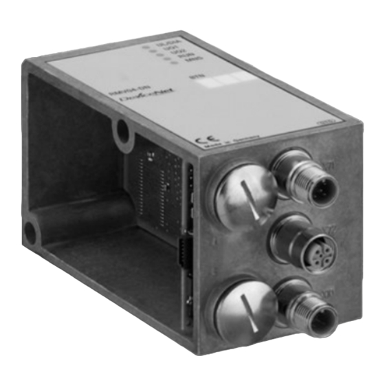
AVENTICS | PROFINET-IO | R412015162–BDL–001–AE About This Product Device components 4.4.1 Bus coupler Fig. 2: Bus coupler with M12 sockets and plugs (left), bus coupler with 7/8" plug (right) 1 LED displays for diagnostic messages 2 Bus slave label 3 X71 (BUS) 4 X72 (BUS) 5 (left) X10 (POWER) M12 connection to supply power to the valve solenoids, logic, and inputs;... -
Page 73: Input/Output Modules
AVENTICS | PROFINET-IO | R412015162–BDL–001–AE About This Product Diagnosis The logic and valve control power supplies are monitored. If the voltages fall below a set limit, an error signal will be generated and reported via the diagnostic LEDs and diagnostic information. -
Page 74: Input Modules
AVENTICS | PROFINET-IO | R412015162–BDL–001–AE About This Product 4.4.3 Input modules The input modules used to connect electric sensor signals are available in two versions: 8x M8 (RMV04-8DI_M8) or 4x M12, double-assigned (RMV04-8DI_M12) Fig. 3: 8x input module: RMV04-8DI_M8 (left) and RMV04-8DI_M12 (right) -
Page 75: Output Modules
AVENTICS | PROFINET-IO | R412015162–BDL–001–AE About This Product 4.4.4 Output modules The output modules used to connect the actuators are available in two versions: 8x M8 (RMV04-8DO_M8) or 4x M12, double-assigned (RMV04-8DO_M12) Fig. 4: 8x output module: RMV04-8DO_M8 (left) and RMV04-8DO_M12 (right) -
Page 76: Assembly
AVENTICS | PROFINET-IO | R412015162–BDL–001–AE Assembly Assembly Assembling the valve system with the bus coupler You will receive your individually configured valve system completely fitted with all components: Valve terminal Bus coupler Up to six I/O modules (if needed) Up to three module extensions (if needed) The operating instructions accompanying the VS describe in full how to assemble the entire valve system. -
Page 77: Connecting The Modules Electrically
AVENTICS | PROFINET-IO | R412015162–BDL–001–AE Assembly The markings on the connections indicate which labels are assigned to the connections. Fig. 5: Labels on the bus coupler (CMS-B-PNRT_32), input module (8DI_M8) and output module (8DO_M8), examples Connecting the modules electrically CAUTION Applied voltage Danger of injury from electric shocks. - Page 78 AVENTICS | PROFINET-IO | R412015162–BDL–001–AE Assembly NOTICE Faulty wiring Faulty wiring can lead to malfunctions as well as damage to the network. Unless otherwise stipulated, comply with the PROFINET-IO specifications. Only a cable that meets the fieldbus specifications as well as the connection speed and length requirements should be used.
-
Page 79: General Notes On Connecting The Bus Coupler
AVENTICS | PROFINET-IO | R412015162–BDL–001–AE Assembly 5.3.1 General notes on connecting the bus coupler Use pre-assembled plug connections to connect the modules. Observe the pin assignment in Table 79 if you do not use pre-assembled plug connections and cables. Table 5:... -
Page 80: Connecting The Bus Coupler
AVENTICS | PROFINET-IO | R412015162–BDL–001–AE Assembly 5.3.2 Connecting the bus coupler 1. Set up the correct pin assignment (see Table 5 on page 79) on the plug connections if you do not use pre-assembled cables. 2. Connect the incoming bus connection to X71 (2) and connect the module with a hub or switch if further slaves are to be connected. -
Page 81: Pin Assignment For Bus Coupler With 7/8" Plug For Power Supply
AVENTICS | PROFINET-IO | R412015162–BDL–001–AE Assembly The power supply cable must fulfil the following requirements: Cable socket: 4-pin, A-coded without center hole Cable cross-section: per wire ≥ 0.5 mm Length: max. 20 m Table 8: Power consumption on X10 (POWER) on bus coupler... -
Page 82: Connecting The Bus Coupler Logic And Load Supply
AVENTICS | PROFINET-IO | R412015162–BDL–001–AE Assembly The power supply cable must fulfil the following requirements: Cable socket: 5-pin, 7/8" Cable cross-section: per wire ≥ 0.5 mm Length: max. 20 m Table 10: Power consumption on X10 (POWER) on bus coupler... -
Page 83: Connecting The 8X Input/Output Modules
AVENTICS | PROFINET-IO | R412015162–BDL–001–AE Assembly To connect the bus coupler load supply: 1. Set up the correct pin assignment (see Table 7 on page 80 or see Table 9 on page 81) on the plug connections if you are not using pre-assembled cables. - Page 84 AVENTICS | PROFINET-IO | R412015162–BDL–001–AE Assembly Table 11: Input assignment for 8x input module, 8DI_M8, M8x1 socket I0…I7 Signal Assignment SENSOR+ Sensor supply + SENSOR- Reference potential I0 to I7 Sensor signal Housing Connected to shield potential Table 12: Input assignment for 8x input module, 8DI_M12,...
-
Page 85: Connecting The Output Module Load Supply
AVENTICS | PROFINET-IO | R412015162–BDL–001–AE Assembly Table 14: Output assignment for 8x output module, 8DO_M12, M12x1 socket Signal Assignment Not connected O1, O3, O5 or O7 Output signal Reference potential O0, O2, O4 or O6 Output signal Not connected Housing... -
Page 86: Fe Connection
PROFINET-IO fieldbus interface Ethernet Type Potential separation Any in acc. with RFC specifications Station address 100 MBaud Baud rate The bus coupler can be operated on a PROFINET-IO fieldbus with real-time classes RT and IRT. -
Page 87: Commissioning And Operation
AVENTICS | PROFINET-IO | R412015162–BDL–001–AE Commissioning and Operation Commissioning and Operation No changes may be made to the configuration and hardware during operation! Making presettings The following presettings have to be made: Assigning the valve supply on the bus coupler with M12 plug... - Page 88 AVENTICS | PROFINET-IO | R412015162–BDL–001–AE Commissioning and Operation On Off S3.8 S3.7 Fig. 6: (A) S3.1–S3.8 monitoring threshold for valve voltages (see Table 19 on page 92); (B) switch S4, S5, S6, S7 for assignment of valve supply voltages (U...
- Page 89 AVENTICS | PROFINET-IO | R412015162–BDL–001–AE Commissioning and Operation NOTICE Voltage at switches Switches can be damaged if voltage is applied during operation. Always operate switches in a voltage-free state! How to assign the valve supply: 1. Open the lower screw cap B (see Fig. 6 on page 88).
- Page 90 AVENTICS | PROFINET-IO | R412015162–BDL–001–AE Commissioning and Operation Table 17: Examples for assignment of switches and valve supply Example 1 Example 2 Example 3 Double subbase for double solenoid valves Valve Valve Valve Sol. LED Sol. LED Sol. LED position...
- Page 91 AVENTICS | PROFINET-IO | R412015162–BDL–001–AE Commissioning and Operation Table 18: Examples for assignment of switches and valve supply Example 4 Example 5 Example 6 Double subbase for single Double subbase for single solenoid and double solenoid valves solenoid valves Valve...
-
Page 92: Setting The Diagnostic Messages
AVENTICS | PROFINET-IO | R412015162–BDL–001–AE Commissioning and Operation 6.1.2 Setting the diagnostic messages The S3 mode switch used to set the diagnostic messages is located under the PG fitting A (see Fig. 6 and Fig. 7 on page 88). When delivered, the diagnosis is deactivated (S3.1 – 3.6 set... -
Page 93: Switching The Tolerance Level For Valve Supply U Q1 And U Q2
AVENTICS | PROFINET-IO | R412015162–BDL–001–AE Commissioning and Operation 6.1.3 Switching the tolerance level for valve supply and U The threshold 20.4 V and 21.6 V can be adjusted for different valve series. In the delivery condition, the threshold (see Table 19 on page 92) is set to 21.6 V (10%) (S 3.7 and S 3.8 set to ON). -
Page 94: Configuring The Network
The following example is based on the SIMATIC software from Siemens. The work described here may only be carried out by qualified electronics personnel and in compliance with the operator's documentation on configuring the PROFINET-IO controller, as well as applicable technical standards, directives, and safety regulations. - Page 95 AVENTICS | PROFINET-IO | R412015162–BDL–001–AE Commissioning and Operation Before starting configuration, the following steps must have been carried out and completed on the bus coupler: You have assembled the bus coupler and valve terminal (see “Assembly” on page 76). You have connected the bus coupler (see “Connecting the modules electrically”...
- Page 96 AVENTICS | PROFINET-IO | R412015162–BDL–001–AE Commissioning and Operation The new slave is shown with the IP address 0.0.0.0 (or an already-configured address). It is then selected. Now an appropriate IP address and subnet mask can be assigned (example 192.168.0.3/255.255.255.0) and allocated (IP-Konfiguration zuweisen).
- Page 97 AVENTICS | PROFINET-IO | R412015162–BDL–001–AE Commissioning and Operation In the hardware configuration, the configured slave must be assigned to the previously allocated IP address and device name (example “cms2”). The manually or automatically assigned IP addresses must be entered for the configured slaves.
-
Page 98: Test, Diagnosis, And Error Messages On The Modules
(e.g. emergency OFF) Bus error LNK/ACT 1 Yellow Active data exchange with network Green Port connection to PROFINET-IO network active LNK/ACT 2 Yellow Active data exchange with network Green Port connection to PROFINET-IO network active Load supply U –... - Page 99 AVENTICS | PROFINET-IO | R412015162–BDL–001–AE Commissioning and Operation Valve diagnosis – Short circuit message disappears after the problem has been remedied. OPEN-LOOP detection only disappears once the error has been remedied and the valve solenoid has switched again. If during the voltage diagnosis all three messages –...
- Page 100 AVENTICS | PROFINET-IO | R412015162–BDL–001–AE Commissioning and Operation Table 22: Diagnostic values Value for SREG channel channel System Info Description over- under- under- short open short missing missing error load Voltage Voltage circuit loop circuit Slot Indicates which 1 (VS)
-
Page 101: System Error
AVENTICS | PROFINET-IO | R412015162–BDL–001–AE Commissioning and Operation 6.3.2 System error The following errors can be detected by the device. Table 23: System error Error Description Reaction SREG Internal communication has Set the PN malfunctioned. diagnostic alarm An internal processing error “System Error”... -
Page 102: Check Sensors On The Input Module
AVENTICS | PROFINET-IO | R412015162–BDL–001–AE Commissioning and Operation 6.3.3 Check sensors on the input module There is one LED per input on the input module for monitoring purposes. The LED lights up if the signal level is “high”. Before commissioning the system, check the sensor function and method of operation by reading the LEDs. -
Page 103: Check Actuators On The Output Module
AVENTICS | PROFINET-IO | R412015162–BDL–001–AE Commissioning and Operation 6.3.4 Check actuators on the output module Before commissioning, check the actuator function and the method of operation using the LED displays on the output module. Fig. 9: LED displays on the M8 output module (left) and M12 (right) -
Page 104: Commissioning The Bus Coupler
AVENTICS | PROFINET-IO | R412015162–BDL–001–AE Commissioning and Operation Commissioning the bus coupler Before commissioning the system, the following steps must have been carried out and completed: You have assembled the valve terminals and the bus coupler (see “Assembling the valve system with the bus coupler” on page 76). -
Page 105: Disassembly And Exchange
You can either exchange the bus coupler or connect additional input/output modules and module extensions as needed. The AVENTICS warranty only applies to the delivered configuration and extensions taken into account in the configuration. The warranty no longer applies after a conversion that exceeds these extensions. - Page 106 AVENTICS | PROFINET-IO | R412015162–BDL–001–AE Disassembly and Exchange 7. Make all the presettings on the new bus coupler (4) (see “Making presettings” on page 87). 8. Reestablish the connections. 9. Check the configuration and adjust it if necessary (see “Configuring the network” on page 94).
-
Page 107: Mounting Input/Output Module(S)
AVENTICS | PROFINET-IO | R412015162–BDL–001–AE Disassembly and Exchange Mounting input/output module(s) Input and output modules can be added to the valve system. See Fig. 11 on page 108. CAUTION Applied voltage and high pressure! Danger of injury from electric shocks and sudden pressure drops. - Page 108 AVENTICS | PROFINET-IO | R412015162–BDL–001–AE Disassembly and Exchange CAUTION Open inputs/outputs Danger of electric shocks caused by contact, short circuits, or damage to the system. Always close unused inputs or outputs with protective caps (see accessories) to comply with the IP 65 protection class.
-
Page 109: Care And Maintenance
AVENTICS | PROFINET-IO | R412015162–BDL–001–AE Care and Maintenance Care and Maintenance CAUTION Applied voltage and high pressure! Danger of injury from electric shocks and sudden pressure drops. Make sure the system is not under pressure or voltage before carrying out any service and maintenance work. -
Page 110: Technical Data
AVENTICS | PROFINET-IO | R412015162–BDL–001–AE Technical Data Technical Data Characteristics General Protection class according to EN 60529/IEC 529 IP 65 when assembled Ambient temperature Operation 0°C to +50°C, without condensation Storage -20°C to +70°C Electromagnetic compatibility Interference emission EN 61000-6-4... -
Page 111: 8X Input Modules, Rmv04-8Di_M8 And Rmv04-8Di_M12
AVENTICS | PROFINET-IO | R412015162–BDL–001–AE Technical Data 8x input modules, RMV04-8DI_M8 and RMV04-8DI_M12 Electrics Inputs DIN EN 61131-2 8 digital inputs, type 3, two-wire proximity switch with a quiescent current of max. 2.5 mA can be connected Total current of 24 V sensor supply for all input modules limited to 0.7 A. -
Page 112: 10 Spare Parts And Accessories
AVENTICS | PROFINET-IO | R412015162–BDL–001–AE Spare parts and accessories 10 Spare parts and accessories 10.1 Bus coupler Order number Bus coupler with M12 power supply plug R412014581 Bus coupler with 7/8" power supply plug R412014582 Accessories M12x1 protective cap for inputs (packaging unit = 25 pcs) -
Page 113: Power Plug For Bus Coupler And Output Module
AVENTICS | PROFINET-IO | R412015162–BDL–001–AE Disposal 10.3 Power plug for bus coupler and output module Order number Plug connector for power supply, M12x1 socket, 180° (X10, POWER) 8941054324 4-pin for cable Ø 4 – 8 mm, A-coded 90° (X10, POWER) 8941054424 Plug-in connection for power supply plug 7/8",... - Page 114 AVENTICS | PROFINET-IO | R412015162–BDL–001–AE Disposal...
-
Page 115: 12 Index
AVENTICS | PROFINET-IO | R412015162–BDL–001–AE Index 12 Index Abbreviations 65 Diagnostic display, bus coupler 98 Assembly Connecting the 8x Disposal 113 I/O modules 83 Electrical connections 77 Electrical connection FE connection 86 Bus coupler 80 Mounting options 76 FE 86... - Page 116 AVENTICS | PROFINET-IO | R412015162–BDL–001–AE Index Plug connections X10 (POWER) 82, 86 Power supply Connection cable 85 Presettings Assigning the valve supply 87 Qualifications and personnel 67 Safety instructions Cleaning 69 Definitions 63 During assembly 68 During commissioning and operation 69...
- Page 117 AVENTICS | PROFINET-IO | R412015162–BDL–001–AE Sommaire Sommaire A propos de cette documentation ......119 Validité de la documentation..........119 Documentations nécessaires et complémentaires..119 Présentation des informations ..........120 1.3.1 Consignes de sécurité ............120 1.3.2 Symboles .................. 121 1.3.3 Abréviations ................
- Page 118 Raccordement de l’alimentation des distributeurs du module de sortie .............. 143 5.3.8 Raccord FE ................144 Interface pour bus de terrain PROFINET-IO ....144 Mise en service et utilisation ........145 Définition des paramétrages préalables ......145 6.1.1 Affectation de l’alimentation des distributeurs sur le coupleur de bus avec connecteur M12 ....
-
Page 119: Propos De Cette Documentation
Type de Désignation document document Documentation du système de R412008233 Instructions distributeurs Documentation de l’extension de R412008961 Instructions module (optionnelle) Documentation de l’installation Pour de plus amples informations concernant les composants, consulter le catalogue en ligne d’AVENTICS sur le site www.aventics.com/pneumatics-catalog. -
Page 120: Présentation Des Informations
AVENTICS | PROFINET-IO | R412015162–BDL–001–AE A propos de cette documentation Présentation des informations Afin de pouvoir travailler rapidement et en toute sécurité avec ce produit, cette documentation contient des consignes de sécurité, symboles, termes et abréviations standardisés. Ces derniers sont expliqués dans les paragraphes suivants. -
Page 121: Symboles
AVENTICS | PROFINET-IO | R412015162–BDL–001–AE A propos de cette documentation Tableau 2 : Classes de dangers selon la norme ANSI Z535.6-2006 Signal de danger, mot-clé Signification Signale une situation dangereuse susceptible ATTENTION d’entraîner des blessures légères à modérées si le danger n’est pas évité. -
Page 122: Consignes De Sécurité
AVENTICS | PROFINET-IO | R412015162–BDL–001–AE Consignes de sécurité Consignes de sécurité A propos de ce chapitre Le produit a été fabriqué selon les règles techniques généralement reconnues. Des dommages matériels et corporels peuvent néanmoins survenir si ce chapitre de même que les consignes de sécurité... -
Page 123: Utilisation Non Conforme
(sécurité fonctionnelle). AVENTICS GmbH décline toute responsabilité en cas de dommages résultant d’une utilisation non conforme. Toute utilisation non conforme est aux risques et périls de l’utilisateur. -
Page 124: Consignes Générales De Sécurité
Il n’est admis de mettre le produit en service que lorsqu’il a été constaté que le produit final (par exemple une machine ou une installation) dans lequel les produits AVENTICS sont utilisés satisfait bien aux dispositions du pays d’utilisation, prescriptions de sécurité et normes de l’application. -
Page 125: Consignes De Sécurité Selon Le Produit Et La Technique125
AVENTICS | PROFINET-IO | R412015162–BDL–001–AE Consignes de sécurité Consignes de sécurité selon le produit et la technique Ne surcharger en aucun cas l’appareil de manière mécanique. Ne jamais y déposer d’objets. S’assurer que l’alimentation en tension se situe dans la plage de tolérance indiquée pour les modules. -
Page 126: Fourniture
AVENTICS | PROFINET-IO | R412015162–BDL–001–AE Fourniture des raccords enfichables soient étanches, afin d’éviter que des liquides et des corps solides puissent pénétrer dans l’appareil. Lors du fonctionnement Assurer une aération ou un refroidissement suffisant lorsque le système de distributeurs présente les caractéristiques suivantes :... -
Page 127: Description De L'appareil
électriques d’entrée et de sortie par le raccordement bus du système de distributeurs. Le coupleur de bus est exclusivement destiné à fonctionner en tant qu’esclave dans un système bus PROFINET-IO selon la norme IEC 61158. Description du produit Le coupleur de bus permet la commande du VS via un système Ethernet. -
Page 128: Vue D'ensemble Du Système De Distributeurs Et Des Modules
AVENTICS | PROFINET-IO | R412015162–BDL–001–AE Description de l’appareil Vue d’ensemble du système de distributeurs et des modules Selon la commande, le système de distributeurs est constitué des composants représentés à la Fig. 1 : Fig. 1 : Vue d’ensemble : exemple de configuration coupleur de bus avec modules E/S et porte- distributeurs) 1 Embase terminale à... -
Page 129: Composants
; (à droite) Connexion 7/8" pour alimentation en tension des bobines de distributeurs 7 Couvercle de protection A pour commutateur DIP S3 Le coupleur de bus est exclusivement destiné à fonctionner en tant que dispositif dans un réseau PROFINET-IO. -
Page 130: Modules D'entrée / De Sortie
AVENTICS | PROFINET-IO | R412015162–BDL–001–AE Description de l’appareil Le coupleur de bus se raccorde par un câble directement à une commande, un contacteur ou un autre coupleur de bus, conformément aux spécifications PROFINET-IO. Diagnostic Les tensions d’alimentation pour les circuits logiques et la commande des distributeurs sont surveillées. -
Page 131: Modules D'entrée
AVENTICS | PROFINET-IO | R412015162–BDL–001–AE Description de l’appareil 4.4.3 Modules d’entrée Les modules d’entrée destinés à la connexion des signaux électriques de capteurs sont disponibles en deux versions. 8 x M8 (RMV04-8DI_M8) ou 4 x M12, double affectation (RMV04-8DI_M12) Fig. 3 : Module d’entrée 8x : RMV04-8DI_M8 (à gauche) et RMV04-8DI_M12 (à droite) 1 Case d’inscription... -
Page 132: Modules De Sortie
AVENTICS | PROFINET-IO | R412015162–BDL–001–AE Description de l’appareil 4.4.4 Modules de sortie Les modules de sortie destinés à la connexion des actionneurs sont disponibles en deux versions : 8 x M8 (RMV04-8DO_M8) ou 4 x M12, double affectation (RMV04-8DO_M12) Fig. 4 : Module de sortie 8x : RMV04-8DO_M8 (à gauche) et RMV04-8DO_M12 (à droite) 1 Case d’inscription... -
Page 133: Montage
AVENTICS | PROFINET-IO | R412015162–BDL–001–AE Montage Montage Montage du coupleur de bus sur le système de distributeurs Le système de distributeurs est livré individuellement configuré, complètement vissé avec tous les composants : Porte-distributeurs Coupleur de bus Jusqu’à six modules E/S, le cas échéant Jusqu’à... -
Page 134: Raccordement Électrique Des Modules
AVENTICS | PROFINET-IO | R412015162–BDL–001–AE Montage La description des raccordements indique l’affectation des cases d’inscription aux raccordements. Fig. 5 : Cases d’inscription sur le coupleur de bus (CMS-B-PNRT_32), module d’entrée (8DI_M8) et module de sortie (8DO_M8), exemples Raccordement électrique des modules ATTENTION Tension électrique... - Page 135 AVENTICS | PROFINET-IO | R412015162–BDL–001–AE Montage REMARQUE Câblage erroné Un câblage erroné ou défectueux provoque des dysfonctionnements ou des dommages au réseau. Sauf indications contraires, respecter les spécifications PROFINET-IO. Veiller à utiliser uniquement des câbles correspondant aux spécifications bus et répondant aux exigences de vitesse et de longueur de la connexion.
-
Page 136: Remarques Générales Concernant Le Raccordement Du Coupleur De Bus
AVENTICS | PROFINET-IO | R412015162–BDL–001–AE Montage 5.3.1 Remarques générales concernant le raccordement du coupleur de bus Pour raccorder les modules, utiliser des raccords enfichables et des câbles confectionnés. Lors de l’utilisation de raccords enfichables et de câbles non confectionnés, respecter l’affectation des broches représentée dans le Tab. -
Page 137: Raccordement Du Coupleur De Bus
AVENTICS | PROFINET-IO | R412015162–BDL–001–AE Montage 5.3.2 Raccordement du coupleur de bus 1. En cas d’utilisation de câbles non confectionnés, effectuer l’affectation correcte des broches (voir le tableau 5 à la page 136) des raccords enfichables. 2. Raccorder le câble bus à X71 (2) et relier le module à un contacteur si d’autres participants doivent être raccordés. - Page 138 AVENTICS | PROFINET-IO | R412015162–BDL–001–AE Montage et U sont reliés entre eux de façon galvanique. Il est possible d’alimenter les distributeurs par l’alimentation de distributeurs U et U de façon groupée. L’affectation des groupes de distributeurs (4 ou 8 distributeurs) s’effectue par l’intermédiaire des commutateurs à...
-
Page 139: Affectation Des Broches Pour Coupleur De Bus Avec Connecteur 7/8" Pour Alimentation En Tension
AVENTICS | PROFINET-IO | R412015162–BDL–001–AE Montage 5.3.4 Affectation des broches pour coupleur de bus avec connecteur 7/8" pour alimentation en tension Lors du raccordement de l’alimentation du circuit logique et des distributeurs du coupleur de bus, respecter l’affectation des broches représentée dans le tableau 9. -
Page 140: Raccordement De L'alimentation Des Circuits Logiques Et Des Distributeurs Du Coupleur De Bus
AVENTICS | PROFINET-IO | R412015162–BDL–001–AE Montage 5.3.5 Raccordement de l’alimentation des circuits logiques et des distributeurs du coupleur de bus Les distributeurs et le coupleur de bus sont alimentés par le connecteur X10 (POWER). ATTENTION Tensions dangereuses Un bloc d’alimentation dont la mise en service n’est pas sécurisée peut, en cas de dysfonctionnement, provoquer des... -
Page 141: Raccordement Des Modules D'entrée / De Sortie 8X
AVENTICS | PROFINET-IO | R412015162–BDL–001–AE Montage 5.3.6 Raccordement des modules d’entrée / de sortie 8x ATTENTION Pièces conductrices de courant librement accessibles Risque d’électrocution par contact ! Lors du raccordement de la périphérie (interface E/S), respecter les exigences de la protection contre les contacts conformément à... - Page 142 AVENTICS | PROFINET-IO | R412015162–BDL–001–AE Montage Tableau 12 : Affectation des entrées pour le module d’entrée 8x, 8DI_M12, douille M12x1 Broche Signal Affectation CAPTEUR+ Alimentation capteur + 24 V I1, I3, I5 ou I7 Signal capteur SENSOR- Potentiel de référence GND...
-
Page 143: Raccordement De L'alimentation Des Distributeurs Du Module De Sortie
AVENTICS | PROFINET-IO | R412015162–BDL–001–AE Montage REMARQUE Somme des intensités trop élevée Chaque sortie est prévue pour un courant permanent de maximum 0,5 A. Des charges électriques supérieures à 0,5 A par sortie peuvent endommager le système. Veiller à ce que la charge électrique ne soit pas supérieure à... -
Page 144: Raccord Fe
Séparation du potentiel Libre conformément aux directives RFC Adresse de la station 100 MBaud Débit en bauds La mise en service du bus peut être activée sur un bus de terrain PROFINET-IO des classes de temps réel RT et IRT. -
Page 145: Mise En Service Et Utilisation
AVENTICS | PROFINET-IO | R412015162–BDL–001–AE Mise en service et utilisation Mise en service et utilisation Lors du fonctionnement, aucune modification ne doit être opérée quant à la configuration et au matériel informatique ! Définition des paramétrages préalables Effectuer les préréglages suivants : Affectation de l’alimentation des distributeurs sur le... - Page 146 AVENTICS | PROFINET-IO | R412015162–BDL–001–AE Mise en service et utilisation On Off S3.8 S3.7 Fig. 6: (A) S3.1–S3.8 Seuil de contrôle pour tensions de distributeurs (voir Tab. 19 à la page 151) ; (B) Commutateurs S4, S5, S6 et S7 pour l’affectation des tensions d’alimentation de distributeurs...
- Page 147 AVENTICS | PROFINET-IO | R412015162–BDL–001–AE Mise en service et utilisation Tableau 16 : Affectation des commutateurs S4, S5, S6 et S7 Embases doubles pour distributeurs Embases doubles pour distributeurs Commutateur Octet bistables (bobines 12 et 14) monostables (bobine 14) 1 – 4 1 –...
- Page 148 AVENTICS | PROFINET-IO | R412015162–BDL–001–AE Mise en service et utilisation Ci-après sont présentés des exemples pour l’affectation des commutateurs S4, S5, S6 et S7 et l’alimentation de distributeurs montés, au Tab. 17 à la page 149 (exemples 1 à 3) et au Tab. 18 à...
- Page 149 AVENTICS | PROFINET-IO | R412015162–BDL–001–AE Mise en service et utilisation Tableau 17 : Exemples pour l’affectation de commutateurs et l’alimentation des distributeurs Exemple 1 Exemple 2 Exemple 3 Embase double pour distributeurs bistables Empl. Empl. Empl. Bobine LED Bobine LED Bobine LED distrib.
- Page 150 AVENTICS | PROFINET-IO | R412015162–BDL–001–AE Mise en service et utilisation Tableau 18 : Exemples pour l’affectation de commutateurs et l’alimentation des distributeurs Exemple 4 Exemple 5 Exemple 6 Embase double pour Embase double pour distributeurs distributeurs bistables monostables et bistables Empl.
-
Page 151: Paramétrage Des Notifications De Diagnostic
AVENTICS | PROFINET-IO | R412015162–BDL–001–AE Mise en service et utilisation 6.1.2 Paramétrage des notifications de diagnostic Le commutateur de mode S3 pour le paramétrage des notifications de diagnostic se trouve sous le vissage PG A (voir Fig. 6 et Fig. 7 à la page 146). -
Page 152: Commutation Du Niveau De Tolérance De L'alimentation Des Distributeurs U
AVENTICS | PROFINET-IO | R412015162–BDL–001–AE Mise en service et utilisation 6.1.3 Commutation du niveau de tolérance de l’alimentation des distributeurs U et U Pour diverses séries de distributeurs, les seuils 20,4 V et 21,6 V peuvent être adaptés. A la livraison, le seuil (voir Tab. 19 à la page 151) est réglé... -
Page 153: Configuration Du Réseau
Les travaux décrits ne doivent être effectués que par un personnel spécialisé en électronique et en respectant la documentation de l’exploitant concernant la configuration du contrôleur PROFINET-IO ainsi qu’en respectant les normes techniques en vigueur, les directives et les consignes de sécurité. - Page 154 AVENTICS | PROFINET-IO | R412015162–BDL–001–AE Mise en service et utilisation Avant la configuration, il faut avoir effectuer et clôturer les travaux suivants sur le coupleur de bus : Monter le coupleur de bus et le porte-distributeurs (voir « Montage » à la page 133).
- Page 155 AVENTICS | PROFINET-IO | R412015162–BDL–001–AE Mise en service et utilisation Le nouveau participant s’affiche avec l’adresse IP 0.0.0.0 (ou une adresse déjà configurée). Sélectionner ce participant. Il est à présent possible d’attribuer une adresse IP ou un masque de sous-réseau approprié(e) (exemple 192.168.0.3/ 255.255.255.0) et de l’affecter en cliquant sur «...
- Page 156 AVENTICS | PROFINET-IO | R412015162–BDL–001–AE Mise en service et utilisation Dans la configuration du matériel informatique, il faut à présent attribuer l’adresse IP attribuée auparavant et le nom de l’appareil (exemple "cms2") au participant configuré. Les adresses IP attribuées manuellement ou automatiquement doivent être saisies dans les participants configurés.
-
Page 157: Test, Diagnostic Et Messages D'erreur Sur Les Modules
Rouge Erreur de bus LNK/ACT 1 Jaune Echange de données actif avec le réseau Vert Liaison du port au réseau PROFINET-IO active LNK/ACT 2 Jaune Echange de données actif avec le réseau Vert Liaison du port au réseau PROFINET-IO active Alimentation des distributeurs U –... - Page 158 AVENTICS | PROFINET-IO | R412015162–BDL–001–AE Mise en service et utilisation Diagnostic de distributeur – Le message de court-circuit disparaît après la résolution du problème. La détection Open Loop ne disparaît qu’après réparation de l’erreur et commutation suivante des bobines de distributeur.
- Page 159 AVENTICS | PROFINET-IO | R412015162–BDL–001–AE Mise en service et utilisation Tableau 22 : Valeurs de diagnostic Valeur pour SREG channe channel System INFO Description over under under missin short l open short missing error load voltage voltage circuit loop circuit...
-
Page 160: Erreur De Système
AVENTICS | PROFINET-IO | R412015162–BDL–001–AE Mise en service et utilisation 6.3.2 Erreur de système L’appareil peut détecter les erreurs suivantes. Tableau 23 : Erreur de système Erreur Description Réaction SREG La communication interne Activation de l’alarme est perturbée : de diagnostic PN Une erreur interne de "System Error"... -
Page 161: Vérification Des Capteurs Sur Le Module D'entrée
AVENTICS | PROFINET-IO | R412015162–BDL–001–AE Mise en service et utilisation 6.3.3 Vérification des capteurs sur le module d’entrée Afin d’effectuer les contrôles, une LED est disponible sur le module d’entrée pour chaque entrée. Elle s’allume lorsque le niveau de signal est élevé (high). -
Page 162: Vérification Des Actionneurs Au Niveau Du Module De Sortie
AVENTICS | PROFINET-IO | R412015162–BDL–001–AE Mise en service et utilisation 6.3.4 Vérification des actionneurs au niveau du module de sortie Avant la mise en service, contrôler le bon fonctionnement et le mode d’action des actionneurs à l’aide des affichages LED sur le module de sortie. -
Page 163: Mise En Service Du Coupleur De Bus
AVENTICS | PROFINET-IO | R412015162–BDL–001–AE Mise en service et utilisation Mise en service du coupleur de bus Avant de mettre le système en service, effectuer et clôturer les travaux suivants : Monter le porte-distributeurs et le coupleur de bus (voir « Montage du coupleur de bus sur le système de distributeurs »... -
Page 164: Démontage Et Remplacement
Si nécessaire, il est possible de remplacer le coupleur de bus ou d’installer d’autres modules d’entrée / de sortie ainsi que des extensions de module supplémentaires. La garantie d’AVENTICS n’est valable que pour la configuration livrée et les extensions ayant été prises en compte lors de celle-ci. Après une transformation... -
Page 165: Remplacement Du Coupleur De Bus
AVENTICS | PROFINET-IO | R412015162–BDL–001–AE Démontage et remplacement Remplacement du coupleur de bus Respecter la Fig. 10 à la page 166. ATTENTION Tension électrique et pression importante Risque de blessure dû à une chute de pression subite et une électrocution. -
Page 166: Ajout De Module(S) D'entrée / De Sortie
AVENTICS | PROFINET-IO | R412015162–BDL–001–AE Démontage et remplacement Fig. 10 : Remplacement du coupleur de bus, exemple 1 Vis à six pans creux 4 Coupleur de bus 2 Embase terminale à gauche 5 Tirants 3 Joint 6 Embase terminale à gauche avec orifices Ajout de module(s) d’entrée / de sortie... - Page 167 AVENTICS | PROFINET-IO | R412015162–BDL–001–AE Démontage et remplacement Au total, 6 modules au maximum (modules d’entrée ou de sortie) peuvent être raccordés à un système de distributeurs. Respecter les charges électriques autorisées ! 1. Détacher l’embase terminale gauche (2) du coupleur de bus (7) ou du dernier module d’entrée (5) / de sortie (4) du système de...
- Page 168 AVENTICS | PROFINET-IO | R412015162–BDL–001–AE Démontage et remplacement Fig. 11 : Ajout de modules d’entrée / de sortie, exemple 1 Vis à six pans creux 5 Module d’entrée 2 Embase terminale à gauche 6 Tirants 3 Joint 7 Coupleur de bus...
-
Page 169: Entretien Et Maintenance
AVENTICS | PROFINET-IO | R412015162–BDL–001–AE Entretien et maintenance Entretien et maintenance ATTENTION Tension électrique et pression importante Risque de blessure dû à une chute de pression subite et une électrocution. Mettre le système hors pression et hors tension avant de réaliser des travaux d’entretien et de maintenance. -
Page 170: Données Techniques
AVENTICS | PROFINET-IO | R412015162–BDL–001–AE Données techniques Données techniques Caractéristiques Généralités Indice de protection selon la norme EN 60529 / IEC 529 IP 65 à l’état monté Température ambiante Fonctionnement 0 °C à +50 °C sans condensation Stockage De -20 °C à +70 °C Compatibilité... -
Page 171: Modules D'entrée 8X, Rmv04-8Di_M8 Et Rmv04-8Di_M12
AVENTICS | PROFINET-IO | R412015162–BDL–001–AE Données techniques Modules d’entrée 8x, RMV04-8DI_M8 et RMV04-8DI_M12 Système électrique Entrées DIN EN 61131-2 8 entrées numériques, type 3, possibilité de raccorder un détecteur de proximité à deux fils avec un courant de repos de 2,5 mA max. -
Page 172: Pièces De Rechange Et Accessoires
AVENTICS | PROFINET-IO | R412015162–BDL–001–AE Pièces de rechange et accessoires 10 Pièces de rechange et accessoires 10.1 Coupleur de bus N° de référence Coupleur de bus avec connecteur d’alimentation en tension M12 R412014581 Coupleur de bus avec connecteur d’alimentation en tension 7/8"... -
Page 173: Connecteur Pour Coupleur De Bus Et Module De Sortie
AVENTICS | PROFINET-IO | R412015162–BDL–001–AE Elimination des déchets 10.3 Connecteur pour coupleur de bus et module de sortie N° de référence Connecteur pour alimentation en tension, douille 180° (X10, POWER) 8941054324 M12×1, 4 pôles pour câble de Ø 4 – 8 mm, codé A 90°... - Page 174 AVENTICS | PROFINET-IO | R412015162–BDL–001–AE Elimination des déchets...
-
Page 175: 12 Index
AVENTICS | PROFINET-IO | R412015162–BDL–001–AE Index 12 Index Abréviations 121 Marquage Affectation de l’alimentation Coupleur de bus 133 des distributeurs 145 Modules d’entrée / de sortie 133 Affichage de diagnostic, coupleur de bus 157 Mise en service Alimentation en tension affichage de Câble de connexion 143... - Page 176 AVENTICS | PROFINET-IO | R412015162–BDL–001–AE Index Paramétrages préalables Affectation de l’alimentation des distributeurs 145 Qualification, personnel 123 Raccordement électrique Alimentation du circuit logique et des distributeurs 140 blindage 135 Coupleur de bus 137 Modules d’entrée / de sortie 141 raccordement FE 144...
- Page 177 AVENTICS | PROFINET-IO | R412015162–BDL–001–AE Indice Indice Sulla presente documentazione ......179 Validità della documentazione ......... 179 Documentazione necessaria e complementare..179 Presentazione delle informazioni........180 1.3.1 Indicazioni di sicurezza ............ 180 1.3.2 Simboli ................... 181 1.3.3 Abbreviazioni ............... 181 Indicazioni di sicurezza ..........
- Page 178 5.3.7 Collegamento dell’alimentazione di carico del modulo Output ..........202 5.3.8 Attacco FE ................203 Interfaccia bus di campo PROFINET-IO ......203 Messa in funzione e comando ........204 Esecuzione delle preimpostazioni........204 6.1.1 Assegnazione dell'alimentazione valvole sull'accoppiatore bus con connettore M12 ....204 6.1.2...
-
Page 179: Sulla Presente Documentazione
AVENTICS | PROFINET-IO | R412015162–BDL–001–AE Sulla presente documentazione Sulla presente documentazione Validità della documentazione Le istruzioni contengono informazioni importanti per installare, azionare e sottoporre a manutenzione il prodotto e per riparare autonomamente piccoli guasti, nel rispetto delle norme e della sicurezza. -
Page 180: Presentazione Delle Informazioni
AVENTICS | PROFINET-IO | R412015162–BDL–001–AE Sulla presente documentazione Presentazione delle informazioni Per consentire un impiego rapido e sicuro del prodotto, all’interno della presente documentazione vengono utilizzati indicazioni di sicurezza, simboli, termini e abbreviazioni unitari. Per una migliore comprensione questi sono illustrati nei seguenti paragrafi. -
Page 181: Simboli
AVENTICS | PROFINET-IO | R412015162–BDL–001–AE Sulla presente documentazione Tabella 2: Classi di pericolo secondo ANSI Z535.6–2006 Segnale di avvertimento, Significato parola di segnalazione Indica una situazione pericolosa che, ATTENZIONE se non evitata, può provocare lesioni medie o leggere Danni materiali: il prodotto o NOTA l’ambiente circostante possono... -
Page 182: Indicazioni Di Sicurezza
AVENTICS | PROFINET-IO | R412015162–BDL–001–AE Indicazioni di sicurezza Indicazioni di sicurezza Sul presente capitolo Il prodotto è stato realizzato in base alle regole della tecnica generalmente riconosciute. Ciononostante sussiste il pericolo di lesioni personali e danni materiali, qualora non vengano rispettate le indicazioni di questo capitolo e le indicazioni di sicurezza contenute nella presente documentazione. -
Page 183: Utilizzo Non A Norma
(sicurezza funzionale). In caso di danni per uso non a norma decade qualsiasi responsabilità di AVENTICS GmbH. I rischi in caso di uso non a norma sono interamente a carico dell’utente. Per utilizzo non a norma si intende se l'accoppiatore bus viene impiegato: al di fuori degli ambiti d’applicazione riportati in queste... -
Page 184: Indicazioni Di Sicurezza Generali
Le persone che si occupano del montaggio, del funzionamento, dello smontaggio o della manutenzione dei prodotti AVENTICS non devono essere sotto effetto di alcool, droga o farmaci che alterano la capacità di reazione. Utilizzare solo accessori e ricambi autorizzati dal produttore per escludere pericoli per le persone derivanti dall’impiego... -
Page 185: Indicazioni Di Sicurezza Sul Prodotto E Sulla Tecnologia
AVENTICS | PROFINET-IO | R412015162–BDL–001–AE Indicazioni di sicurezza Indicazioni di sicurezza sul prodotto e sulla tecnologia Non sottoporre in nessun caso l’apparecchio a sollecitazioni meccaniche. Non appoggiarvi mai nessun oggetto. Assicurarsi che l’alimentazione di tensione rientri nel relativo intervallo di tolleranza indicato per i moduli. -
Page 186: Fornitura
Sono compresi nella fornitura di un set di parti per l'accoppiatore bus: 1 accoppiatore bus con guarnizione e due tiranti 1 istruzioni per l'uso per l'accoppiatore bus Il sistema di valvole viene configurato individualmente. Per visualizzare la configurazione esatta basta indicare il codice d’ordine nel configuratore Internet di AVENTICS. -
Page 187: Descrizione Del Prodotto
Descrizione delle prestazioni L'accoppiatore bus serve al pilotaggio elettrico delle valvole tramite il sistema bus di campo PROFINET-IO. I moduli Input/ Output offrono la possibilità di inviare segnali elettrici in ingresso e in uscita tramite l’attacco bus del sistema di valvole. -
Page 188: Panoramica Generale Sistema Di Valvole E Moduli
AVENTICS | PROFINET-IO | R412015162–BDL–001–AE Descrizione del prodotto Panoramica generale sistema di valvole e moduli Il sistema di valvole è costituito, a seconda della fornitura, dai componenti rappresentati nella Fig. 1: Fig. 1: Panoramica prodotto: esempio di configurazione accoppiatore bus con moduli I/O e portavalvole... -
Page 189: Componenti Dell'apparecchiatura
7 Coperchio a vite A per selettore DIP S3 L'accoppiatore bus è concepito esclusivamente per il funzionamento come slave in una rete PROFINET-IO. L'accoppiatore bus viene collegato tramite un cavo secondo la specifica PROFINET-IO direttamente ad un comando, uno switch o un ulteriore accoppiatore bus. -
Page 190: Moduli Input/Output
AVENTICS | PROFINET-IO | R412015162–BDL–001–AE Descrizione del prodotto Diagnosi Le tensioni di alimentazione della logica e del pilotaggio valvole vengono sorvegliate. Se la soglia impostata non viene raggiunta, viene generato un segnale di errore che viene segnalato tramite LED di diagnosi ed informazione di diagnosi. -
Page 191: Moduli Input
AVENTICS | PROFINET-IO | R412015162–BDL–001–AE Descrizione del prodotto 4.4.3 Moduli Input I moduli Input per il collegamento di segnali sensore elettrici sono disponibili in due esecuzioni: 8 x M8 (RMV04-8DI_M8) o 4 x M12, con doppia occupazione (RMV04-8DI_M12) Fig. 3:... -
Page 192: Moduli Output
AVENTICS | PROFINET-IO | R412015162–BDL–001–AE Descrizione del prodotto 4.4.4 Moduli Output I moduli Output per il collegamento degli attuatori sono disponibili in due esecuzioni: 8 x M8 (RMV04-8DO_M8) o 4 x M12, con doppia occupazione (RMV04-8DO_M12) Fig. 4: Modulo Output 8x RMV04-8DO_M8 (a sinistra) e RMV04-8DO_M12 (a destra) -
Page 193: Montaggio
AVENTICS | PROFINET-IO | R412015162–BDL–001–AE Montaggio Montaggio Montaggio del sistema di valvole con accoppiatore bus Ogni sistema di valvole individualmente configurato viene fornito con tutti i componenti completamente avvitati: Portavalvole Accoppiatore bus Eventualmente fino a sei moduli I/O Eventualmente fino a tre ampliamenti del modulo Il montaggio dell’intero sistema di valvole è... -
Page 194: Collegamento Elettrico Dei Moduli
AVENTICS | PROFINET-IO | R412015162–BDL–001–AE Montaggio L’assegnazione dei campi di dicitura agli attacchi è determinata dalla denominazione degli attacchi stessi. Fig. 5: Campi di dicitura sull'accoppiatore bus (CMS-B-PNRT_32), modulo Input (8DI_M8) e modulo Output (8DO_M8), esempi Collegamento elettrico dei moduli... -
Page 195: Indicazioni Generali Sul Collegamento Dell'accoppiatore Bus
AVENTICS | PROFINET-IO | R412015162–BDL–001–AE Montaggio NOTA Cablaggio errato Un cablaggio errato o incorretto provoca malfunzionamento o danni alla rete. Se non indicato diversamente, rispettare le specifiche PROFINET-IO. Utilizzare solo cavi conformi alle specifiche del bus di campo nonché alle caratteristiche del collegamento in materia di velocità... -
Page 196: Collegamento Dell'accoppiatore Bus
AVENTICS | PROFINET-IO | R412015162–BDL–001–AE Montaggio Tabella 5: Occupazione pin X71 (BUS), a 4 poli, con codifica D Segnale Significato Inviare/(ricevere) Ricevere/(inviare) Inviare/(ricevere) Ricevere/(inviare) Corpo schermatura Schermatura/messa a terra Tabella 6: Occupazione pin X72 (BUS), a 4 poli, con codifica D... -
Page 197: Occupazione Pin Per L'accoppiatore Bus Con Connettore M12 Per L'alimentazione Di Tensione
AVENTICS | PROFINET-IO | R412015162–BDL–001–AE Montaggio 5.3.3 Occupazione pin per l'accoppiatore bus con connettore M12 per l'alimentazione di tensione Durante il collegamento dell’alimentazione logica e di carico dell'accoppiatore bus, garantire l’occupazione pin rappresentata in Tabella 6. Tabella 7: Occupazione del connettore dell’apparecchiatura... -
Page 198: Occupazione Pin Per L'accoppiatore Bus Con Connettore 7/8" Per Alimentazione Di Tensione
AVENTICS | PROFINET-IO | R412015162–BDL–001–AE Montaggio 5.3.4 Occupazione pin per l'accoppiatore bus con connettore 7/8" per alimentazione di tensione Durante il collegamento dell’alimentazione logica e di carico dell'accoppiatore bus, garantire l’occupazione pin rappresentata in Tabella 9. Tabella 9: Occupazione del connettore dell'apparecchio X10 (POWER), 7/8"... -
Page 199: Collegamento Dell'alimentazione Logica E Di Carico Dell'accoppiatore Bus
AVENTICS | PROFINET-IO | R412015162–BDL–001–AE Montaggio 5.3.5 Collegamento dell’alimentazione logica e di carico dell'accoppiatore bus L'accoppiatore bus e le valvole vengono alimentati attraverso il connettore dell’apparecchiatura X10 (POWER). ATTENZIONE Tensioni pericolose Un alimentatore con separazione non sicura può provocare tensioni pericolose in caso di errore. Lesioni dovute a scarica di corrente e danni al sistema possono esserne le conseguenze. -
Page 200: Collegamento Moduli Input/Output 8X
AVENTICS | PROFINET-IO | R412015162–BDL–001–AE Montaggio 5.3.6 Collegamento moduli Input/Output 8x ATTENZIONE Componenti alimentatori di corrente liberamente accessibili Pericolo di scarica di corrente in caso di contatto! Durante il collegamento delle parti periferiche (interfaccia I/O) rispettare i requisiti della protezione da contatto secondo EN 50178, classificazione VDE 0160. - Page 201 AVENTICS | PROFINET-IO | R412015162–BDL–001–AE Montaggio Tabella 12: Occupazione degli ingressi in un modulo Input 8x, 8DI_M12, presa M12x1 Segnale Occupazione SENSORE+ Alimentazione sensori da 24 V + I1, I3, I5 o I7 Segnale sensore SENSORE– Potenziale di riferimento GND...
-
Page 202: Collegamento Dell'alimentazione Di Carico Del Modulo Output
AVENTICS | PROFINET-IO | R412015162–BDL–001–AE Montaggio NOTA Corrente cumulativa troppo alta Ogni uscita è progettata per una corrente continua di max. 0,5 A. In caso di carichi di corrente superiori a 0,5 A per uscita, il sistema può essere danneggiato. -
Page 203: Attacco Fe
Interfaccia bus di campo PROFINET-IO Ethernet Tipo Sì Separazione di potenziale A scelta in base alle specificazioni RFC Indirizzo della stazione 100 MBaud Baudrate Il bus può essere collegato ad un bus di campo PROFINET-IO della classe di comunicazione RT e IRT. -
Page 204: Messa In Funzione E Comando
AVENTICS | PROFINET-IO | R412015162–BDL–001–AE Messa in funzione e comando Messa in funzione e comando Durante l'esercizio non devono essere apportate modifiche alla configurazione e all'hardware! Esecuzione delle preimpostazioni Eseguire le seguenti preimpostazioni: Assegnazione dell'alimentazione valvole sul accoppiatore bus con connettore M12 (solo con accoppiatore bus con... - Page 205 AVENTICS | PROFINET-IO | R412015162–BDL–001–AE Messa in funzione e comando On Off S3.8 S3.7 Fig. 6: (A) S3.1–S3.8 Soglia di controllo delle tensioni valvole (ved. Tabella 19 a pag. 209); (B) Interruttori S4, S5, S6, S7 per l'assegnazione delle alimentazioni valvole (U sull'accoppiatore bus con connettore M12 (ved.
- Page 206 AVENTICS | PROFINET-IO | R412015162–BDL–001–AE Messa in funzione e comando NOTA Interruttori sotto tensione Gli interruttori possono essere danneggiati se vengono adoperati in presenza di tensione. Azionare gli interruttori solo in assenza di tensione! Come assegnare l’alimentazione valvole: 1. Aprire il tappo di protezione inferiore B (ved. Fig. 6 a pagina 205).
- Page 207 AVENTICS | PROFINET-IO | R412015162–BDL–001–AE Messa in funzione e comando Tabella 17: Esempi per l’assegnazione degli interruttori e per l’alimentazione valvole Esempio 1 Esempio 2 Esempio 3 Piastra di collegamento doppia per valvole bistabili Posto Posto Posto LED bobina LED bobina...
- Page 208 AVENTICS | PROFINET-IO | R412015162–BDL–001–AE Messa in funzione e comando Tabella 18: Esempi per l’assegnazione degli interruttori e per l’alimentazione valvole Esempio 4 Esempio 5 Esempio 6 Piastra di collegamento doppia Piastra di collegamento doppia per valvole monostabili per valvole bistabili e monostabili...
-
Page 209: Impostazione Delle Segnalazioni Diagnostiche
AVENTICS | PROFINET-IO | R412015162–BDL–001–AE Messa in funzione e comando 6.1.2 Impostazione delle segnalazioni diagnostiche Il selettore di modalità S 3 per l’impostazione delle segnalazioni diagnostiche si trova al di sotto del raccordo A (ved. Fig. 6 e Fig. 7 a pagina 205). -
Page 210: Q1 Q2
AVENTICS | PROFINET-IO | R412015162–BDL–001–AE Messa in funzione e comando 6.1.3 Commutazione del livello di tolleranza dell'alimentazione valvole U Per diverse serie di valvole si può adattare la soglia 20,4 V/ 21,6 V. Alla fornitura la soglia (vedi Tabella 19 a pagina 209) è... -
Page 211: Configurazione Di Rete
L'esempio seguente si basa sul software SIMATIC-Software di Siemens. I lavori descritti devono essere eseguiti esclusivamente da personale qualificato in materia elettronica e nel rispetto della documentazione dell’installatore riguardo alla configurazione del PROFINET-IO-Controller e delle norme tecniche, direttive e normative di sicurezza vigenti. - Page 212 AVENTICS | PROFINET-IO | R412015162–BDL–001–AE Messa in funzione e comando Prima di eseguire la configurazione intraprendere e portare a termine i seguenti lavori sull'accoppiatore bus: Montaggio dell'accoppiatore bus e del portavalvole (ved. “Montaggio” a pagina 193). Collegamento dell'accoppiatore bus (vedi „Collegamento elettrico dei moduli“...
- Page 213 AVENTICS | PROFINET-IO | R412015162–BDL–001–AE Messa in funzione e comando Il nuovo partecipante viene visualizzato con l'indirizzo IP 0.0.0.0 (oppure con un indirizzo già configurato). Questo viene selezionato. Ora può essere trasmesso e assegnato un indirizzo IP adatto ed una subnet mask (esempio 192.168.0.3/255.255.255.0) (IP-Konfiguration zuweisen).
- Page 214 AVENTICS | PROFINET-IO | R412015162–BDL–001–AE Messa in funzione e comando Nella configurazione hardware devono essere assegnati al partecipante configurato solo l'indirizzo IP ed il nome apparecchio (per esempio “cms2”) assegnati in precedenza. Gli indirizzi IP assegnati manualmente o automaticamente devono essere registrati nei partecipanti configurati.
-
Page 215: Test, Diagnosi E Messaggi Di Errore Sui Moduli
Errore bus LNK/ACT 1 giallo Scambio dati attivo con la rete verde Collegamento della porta alla rete PROFINET-IO attivo LNK/ACT 2 giallo Scambio dati attivo con la rete verde Collegamento della porta alla rete PROFINET-IO attivo Alimentazione di carico U –... - Page 216 AVENTICS | PROFINET-IO | R412015162–BDL–001–AE Messa in funzione e comando Diagnosi valvole – Il messaggio di cortocircuito scompare dopo l'eliminazione dell'errore. L'indicazione OPEN-LOOP scompare solo dopo l'eliminazione dell'errore ed il successivo inserimento della bobina valvola. Se durante la diagnosi della tensione vengono segnalati tutti e tre i messaggi –...
- Page 217 AVENTICS | PROFINET-IO | R412015162–BDL–001–AE Messa in funzione e comando Tabella 22: Valori di diagnosi Valore in caso di System SREG channel channel over under under missing missing error short Info Descrizione open short load voltage voltage circuit loop circuit...
-
Page 218: Errore Di Sistema
AVENTICS | PROFINET-IO | R412015162–BDL–001–AE Messa in funzione e comando 6.3.2 Errore di sistema L'apparecchio può riconoscere i seguenti errori. Tabella 23: Errore di sistema Errore Descrizione Reazione SREG La comunicazione interna Impostazione è disturbata: dell'allarme di Si presenta un errore di... -
Page 219: Controllo Dei Sensori Del Modulo Input
AVENTICS | PROFINET-IO | R412015162–BDL–001–AE Messa in funzione e comando 6.3.3 Controllo dei sensori del modulo Input Il modulo Input dispone a scopo di controllo di un LED per ogni ingresso, che si illumina se il livello del segnale è “high” (alto). -
Page 220: Controllo Degli Attuatori Del Modulo Output
AVENTICS | PROFINET-IO | R412015162–BDL–001–AE Messa in funzione e comando 6.3.4 Controllo degli attuatori del modulo Output Prima della messa in funzione controllare la funzionalità e l’efficacia degli attuatori servendosi degli indicatori LED del modulo Output. Fig. 9: Indicatori LED sul modulo Output M8 (a sinistra) e M12... -
Page 221: Messa In Funzione Dell'accoppiatore Bus
AVENTICS | PROFINET-IO | R412015162–BDL–001–AE Messa in funzione e comando Messa in funzione dell'accoppiatore bus Prima di mettere in funzione il sistema, intraprendere e portare a termine i seguenti lavori: Montaggio dell'accoppiatore bus e del portavalvole (ved. “Montaggio del sistema di valvole con accoppiatore bus”... -
Page 222: Smontaggio E Sostituzione
In base alla necessità l'accoppiatore bus può essere sostituito o ampliato tramite ulteriori moduli Input/Output. La garanzia di AVENTICS è valida esclusivamente per la configurazione consegnata e per gli ampliamenti che sono stati tenuti in considerazione durante la configurazione. Se viene eseguita una trasformazione che va al di là... -
Page 223: Sostituzione Dell'accoppiatore Bus
AVENTICS | PROFINET-IO | R412015162–BDL–001–AE Smontaggio e sostituzione Sostituzione dell'accoppiatore bus Prestare attenzione alla Fig. 10 a pagina 224. ATTENZIONE Presenza di tensione elettrica e pressione elevata Pericolo di lesioni a causa di scossa elettrica e di improvvisa caduta della pressione. -
Page 224: Montaggio Dei Moduli Input/Output
AVENTICS | PROFINET-IO | R412015162–BDL–001–AE Smontaggio e sostituzione Fig. 10: Sostituzione dell'accoppiatore bus, esempio 1 Viti esagonali 4 Accoppiatore bus 2 Piastra terminale sinistra 5 Tirante 3 Guarnizione 6 Piastra terminale sinistra con attacchi Montaggio dei moduli Input/Output Il sistema di valvole può essere ampliato con moduli Input e Output. - Page 225 AVENTICS | PROFINET-IO | R412015162–BDL–001–AE Smontaggio e sostituzione In un sistema di valvole possono essere montati in tutto al massimo 6 moduli Input o Output. Rispettare il carico di corrente consentito! 1. Svitare la piastra terminale sinistra (2) dell'accoppiatore bus (7) o dell’ultimo modulo Input (5)/Output (4) del sistema di...
-
Page 226: Cura E Manutenzione
AVENTICS | PROFINET-IO | R412015162–BDL–001–AE Cura e manutenzione Fig. 11: Montaggio del modulo Input/Output, esempio 1 Viti esagonali 5 Modulo Input 2 Piastra terminale sinistra 6 Tirante 3 Guarnizione 7 Accoppiatore bus 4 Modulo Output Cura e manutenzione ATTENZIONE Presenza di tensione elettrica e pressione elevata Pericolo di lesioni a causa di scossa elettrica e di improvvisa caduta della pressione. -
Page 227: Cura Dei Moduli
AVENTICS | PROFINET-IO | R412015162–BDL–001–AE Dati tecnici Cura dei moduli NOTA Danno alla superficie del corpo dovuto a solventi e detergenti aggressivi! Le superfici e le guarnizioni possono essere danneggiate da solventi e detergenti aggressivi. Non usare mai solventi o detergenti aggressivi! Pulire l’apparecchio regolarmente con un panno... -
Page 228: Accoppiatore Bus
AVENTICS | PROFINET-IO | R412015162–BDL–001–AE Dati tecnici Accoppiatore bus Specifiche elettriche Tensione d’esercizio Logica – U 24 V DC (+20 %/–15 %) – I 100 mA – Fusibile dell'alimentazione di tensione 1,2 AF Carico U 24 V DC (da +20 % a -10 %) -
Page 229: Moduli Output 8X, Rmv04-8Do_M8 E Rmv04-8Do_M12
AVENTICS | PROFINET-IO | R412015162–BDL–001–AE Parti di ricambio e accessori Moduli Output 8x, RMV04-8DO_M8 e RMV04-8DO_M12 Specifiche elettriche Uscite DIN EN 61131-2 8 uscite digitali Tensione di uscita Valore nominale 24 V Caduta di tensione con segnale H (alto) 1,5 V... -
Page 230: 10.2 Modulo Input/Output 8X, 8Di/8Do
AVENTICS | PROFINET-IO | R412015162–BDL–001–AE Smaltimento 10.2 Modulo Input/Output 8x, 8DI/8DO Codice d'ordine Codice d’ordine Modulo Input 8x (8 x M8) 8DI_M8 R412003489 Modulo Input 8x (4 x M12) 8DI_M12 R412008040 Modulo Output 8x (8 x M8) 8DO_M8 R412005968 Modulo Output 8x (4 x M12) -
Page 231: 12 Indice Analitico
AVENTICS | PROFINET-IO | R412015162–BDL–001–AE Indice analitico 12 Indice analitico Abbreviazioni 181 Dati caratteristici 227 Dicitura Accoppiatore bus Dati tecnici 228 Accoppiatore bus 193 Ricambi, Accessori 229 Moduli Input/Output 193 Struttura 189 Alimentazione di tensione Cavo di Indicazioni di sicurezza... - Page 232 AVENTICS | PROFINET-IO | R412015162–BDL–001–AE Indice analitico Montaggio Collegamenti Utilizzo a norma 182 elettrici 194 Collegamento dei moduli non a norma 183 Input/Output 8x 200 Collegamento FE 203 Possibilità di montaggio 193 Norme 185 Preimpostazioni Assegnazione alimentazione valvole 204 Qualificazione,...
- Page 233 AVENTICS | PROFINET-IO | R412015162–BDL–001–AE Índice Índice Acerca de esta documentación ........ 237 Validez de la documentación ..........237 Documentación necesaria y complementaria ..... 237 Presentación de la información ........238 1.3.1 Indicaciones de seguridad ..........238 1.3.2 Símbolos ................239 1.3.3...
- Page 234 Conexión de la alimentación de carga del módulo de salida ............261 5.3.8 Conexión FE ................262 Interfaz de bus de campo PROFINET-IO ......263 Puesta en servicio y manejo ........263 Realización de ajustes previos ......... 263 6.1.1 Asignación de la alimentación de válvulas del acoplador de bus con enchufe M12 .......
- Page 235 AVENTICS | PROFINET-IO | R412015162–BDL–001–AE Índice 10.1 Acoplador de bus..............289 10.2 Módulo de entrada/salida óctuple, 8DI/8DO ....290 10.3 Enchufe Power para acoplador de bus y módulo de salida ............... 290 Eliminación de residuos ........... 290 Índice temático ............291...
- Page 236 AVENTICS | PROFINET-IO | R412015162–BDL–001–AE Índice...
-
Page 237: Acerca De Esta Documentación
Acerca de esta documentación Validez de la documentación Estas instrucciones contienen información importante para montar, utilizar y mantener el acoplador de bus PROFINET-IO, y eliminar averías sencillas de un modo seguro y apropiado. Lea esta documentación por completo, especialmente el capítulo “Indicaciones de seguridad”, antes de empezar a... -
Page 238: Presentación De La Información
AVENTICS | PROFINET-IO | R412015162–BDL–001–AE Acerca de esta documentación Presentación de la información Para poder trabajar con su producto de forma rápida y segura gracias a esta documentación, en ella se emplean de forma coherente las indicaciones de seguridad, símbolos, términos y abreviaturas. -
Page 239: Símbolos
AVENTICS | PROFINET-IO | R412015162–BDL–001–AE Acerca de esta documentación Tabla 2: Clases de peligros según ANSI Z535.6-2006 Símbolo de advertencia, palabra de advertencia Significado Identifica una situación de peligro en la que puede ATENCIÓN existir riesgo de lesiones de carácter leve o leve- medio. -
Page 240: Indicaciones De Seguridad
AVENTICS | PROFINET-IO | R412015162–BDL–001–AE Indicaciones de seguridad Indicaciones de seguridad Sobre este capítulo Este producto ha sido fabricado conforme a las reglas de la técnica generalmente conocidas. No obstante, existe riesgo de sufrir daños personales y materiales si no se tienen en cuenta este capítulo ni las indicaciones de seguridad contenidas en la... -
Page 241: Utilización No Conforme A Las Especificaciones
(seguridad funcional). AVENTICS GmbH no asume responsabilidad alguna por daños debidos a una utilización no conforme a las especificaciones. Los riesgos derivados de una utilización no conforme a las especificaciones son responsabilidad exclusiva del usuario. -
Page 242: Indicaciones De Seguridad Generales
Tenga en cuenta las normativas y disposiciones de seguridad vigentes en el país de utilización del producto. Utilice los productos de AVENTICS solo si no presentan problemas técnicos. Tenga en cuenta todas las indicaciones que figuran en el producto. -
Page 243: Indicaciones De Seguridad Según Producto Y Tecnología
AVENTICS | PROFINET-IO | R412015162–BDL–001–AE Indicaciones de seguridad Indicaciones de seguridad según producto y tecnología En ninguna circunstancia debe someter el aparato a cargas mecánicas. No apoye ningún objeto sobre el mismo. Asegúrese de que la alimentación de tensión se encuentre dentro de la tolerancia indicada de los módulos. -
Page 244: Volumen De Suministro
1 acoplador de bus con junta y dos tirantes 1 manual de instrucciones de servicio del acoplador de bus El VS se configura de manera individual. Podrá ver la configuración exacta con su número de referencia en el configurador de Internet a través de AVENTICS. -
Page 245: Sobre Este Producto
Descripción de las prestaciones El acoplador de bus sirve para el pilotaje eléctrico de las válvulas a través del sistema de bus de campo PROFINET-IO. Los módulos de entrada/salida permiten además conectar señales eléctricas de entrada y salida a través de la conexión de bus del sistema de válvulas. -
Page 246: Vista General Del Sistema De Válvulas Y Los Módulos
AVENTICS | PROFINET-IO | R412015162–BDL–001–AE Sobre este producto Vista general del sistema de válvulas y los módulos El sistema de válvulas se compone, en función del volumen de pedido, de los componentes que se muestran en Fig. 1: Fig. 1: Vista general de los aparatos: configuración a modo de ejemplo acoplador de bus... -
Page 247: Componentes Del Aparato
(derecha) conexión de 7/8" para la alimentación de tensión de las bobinas de válvula 7 Tapa roscada A para el conmutador DIP S3 El acoplador de bus PROFINET-IO se puede utilizar única y exclusivamente como dispositivo en una red PROFINET-IO. -
Page 248: Módulos De Entrada/Salida
AVENTICS | PROFINET-IO | R412015162–BDL–001–AE Sobre este producto Diagnóstico Las tensiones de alimentación para la lógica y el pilotaje de válvulas se supervisan. Si no se alcanza el umbral configurado, se genera una señal de fallo y se notifica mediante los LED de diagnóstico y la información de diagnóstico. -
Page 249: Módulos De Entrada
AVENTICS | PROFINET-IO | R412015162–BDL–001–AE Sobre este producto 4.4.3 Módulos de entrada Los módulos de entrada para conectar señales eléctricas de sensores están disponibles en dos versiones: 8 x M8 (RMV04-8DI_M8) o 4 x M12, con ocupación doble (RMV04-8DI_M12) Fig. 3: Módulo de entrada óctuple: RMV04-8DI_M8 (izquierda) y RMV04-8DI_M12 (derecha) -
Page 250: Módulos De Salida
AVENTICS | PROFINET-IO | R412015162–BDL–001–AE Sobre este producto 4.4.4 Módulos de salida Los módulos de salida para conectar los actuadores están disponibles en dos versiones: 8 x M8 (RMV04-8DO_M8) o 4 x M12, con ocupación doble (RMV04-8DO_M12) Fig. 4: Módulo de salida óctuple: RMV04-8DO_M8 (izquierda) y RMV04-8DO_M12 (derecha) 1 Campo de rotulación... -
Page 251: Montaje
AVENTICS | PROFINET-IO | R412015162–BDL–001–AE Montaje Montaje Montaje del acoplador de bus en el sistema de válvulas Obtendrá su sistema de válvulas configurado de manera individual, atornillado por completo con todos los componentes: Portaválvulas Acoplador de bus Hasta seis módulos de E/S en caso dado Hasta tres ampliaciones de módulo en caso dado... -
Page 252: Conexión Eléctrica De Los Módulos
AVENTICS | PROFINET-IO | R412015162–BDL–001–AE Montaje La denominación de las conexiones indica la asignación de los campos de rotulación a las conexiones. Fig. 5: Campos de rotulación del acoplador de bus (CMS-B-PNRT_32), modulo de entrada (8DI_M8) y módulo de salida (8DO_M8), ejemplos Conexión eléctrica de los módulos... - Page 253 AVENTICS | PROFINET-IO | R412015162–BDL–001–AE Montaje NOTA Cableado incorrecto Un cableado incorrecto o erróneo provoca funciones erróneas y daños en la red. A menos que se indique lo contrario, respete las especificaciones PROFINET-IO. Emplee solamente cables que corresponden a las especificaciones del bus de campo y a los requisitos concernientes a la velocidad y la longitud de la conexión.
-
Page 254: Indicaciones Generales Para La Conexión Del Acoplador De Bus
AVENTICS | PROFINET-IO | R412015162–BDL–001–AE Montaje 5.3.1 Indicaciones generales para la conexión del acoplador de bus Para la conexión de los módulos, utilice conexiones por enchufe y cables confeccionados. Si no utiliza conexiones por enchufe y cables confeccionados, tenga en cuenta la ocupación de pines que se representa en Tab. -
Page 255: Conexión Del Acoplador De Bus
AVENTICS | PROFINET-IO | R412015162–BDL–001–AE Montaje 5.3.2 Conexión del acoplador de bus 1. Si utiliza un cableado confeccionado por usted mismo, establezca la ocupación de pines correcta (véase Tab. 5 en la pág. 254) de sus conexiones por enchufe. 2. Conecte el cable de bus a X71 (2) y conecte el módulo a un switch en caso de que se vayan a conectar más usuarios. -
Page 256: Ocupación De Pines Para Acoplador E Bus Con Enchufe 7/8" Para La Alimentación De Tensión
AVENTICS | PROFINET-IO | R412015162–BDL–001–AE Montaje La asignación de los grupos de válvulas (4 u 8 válvulas) tiene lugar a través de los conmutadores de corredera S4, S5, S6 y S7 (véase “Asignación de la alimentación de válvulas del acoplador de bus con enchufe M12” en la pág. 264). - Page 257 AVENTICS | PROFINET-IO | R412015162–BDL–001–AE Montaje Las tensiones U están separadas entre ellas galvánicamente. La lógica y las entradas se alimentan mediante U Las válvulas se pueden desconectar mediante U El cable para la alimentación de carga debe cumplir las siguientes exigencias: Forro de cable: 5 polos, 7/8"...
-
Page 258: Conexión De La Alimentación De Lógica Y De Carga Del Acoplador De Bus
AVENTICS | PROFINET-IO | R412015162–BDL–001–AE Montaje 5.3.5 Conexión de la alimentación de lógica y de carga del acoplador de bus Las válvulas y el acoplador de bus se alimentan de tensión mediante el enchufe del aparato X10 (POWER). ATENCIÓN Tensiones peligrosas Una fuente de alimentación con una separación no segura... -
Page 259: Conexión De Los Módulos De Entrada/Salida Óctuples
AVENTICS | PROFINET-IO | R412015162–BDL–001–AE Montaje 5.3.6 Conexión de los módulos de entrada/salida óctuples ATENCIÓN Piezas bajo corriente accesibles libremente ¡Peligro de electrocución al tocarlas! Al conectar la periferia (interface E/S) se deben respetar las exigencias de la protección aisladora según la norma EN 50178, clasificación VDE 0160. -
Page 260: Módulo De Salida
AVENTICS | PROFINET-IO | R412015162–BDL–001–AE Montaje Tabla 12: Ocupación de las entradas en el módulo de entrada óctuple, 8DI_M12, casquillo M12x1 Señal Ocupación SENSOR+ Alimentación de sensor 24 V + I1, I3, I5 ó I7 Señal de sensor SENSOR- Potencial de referencia GND I0, I2, I4 ó... -
Page 261: Conexión De La Alimentación De Carga Del Módulo De Salida
AVENTICS | PROFINET-IO | R412015162–BDL–001–AE Montaje NOTA Corriente total demasiado alta Cada salida ha sido concebida para una corriente permanente de máx. 0,5 A. El sistema resulta dañado si se producen cargas de corriente superiores a 0,5 A por cada salida. -
Page 262: Conexión Fe
AVENTICS | PROFINET-IO | R412015162–BDL–001–AE Montaje Tabla 15: Ocupación de la alimentación de carga en el módulo de PO WE R salida óctuple, 8DO, M12x1, con código A Ocupación Libre Referencia GND para alimentación de tensión 2 24 V alimentación de tensión 1 para salidas O0 hasta O3 Referencia GND para alimentación de... -
Page 263: Interfaz De Bus De Campo Profinet-Io
100 MBaud Velocidad en baudios La conexión de bus puede funcionar en un bus de campo PROFINET-IO de las clases de tiempo real RT e IRT. Puesta en servicio y manejo Durante el funcionamiento no deben realizarse modificaciones en la configuración ni en el hardware. -
Page 264: Asignación De La Alimentación De Válvulas Del Acoplador De Bus Con Enchufe M12
AVENTICS | PROFINET-IO | R412015162–BDL–001–AE Puesta en servicio y manejo 6.1.1 Asignación de la alimentación de válvulas del acoplador de bus con enchufe M12 Los conmutadores S4, S5, S6 y S7 para la asignación de la alimentación de válvulas se encuentran bajo el racor PG B (véase Fig. - Page 265 AVENTICS | PROFINET-IO | R412015162–BDL–001–AE Puesta en servicio y manejo Con estos conmutadores las válvulas se pueden asignar en grupos a las tensiones de alimentación U . Todas las válvulas en estado de suministro tienen asignada la tensión U Tabla 16: Asignación de los conmutadores S4, S5, S6 y S7...
- Page 266 AVENTICS | PROFINET-IO | R412015162–BDL–001–AE Puesta en servicio y manejo Más adelante encontrará ejemplos de la asignación de los conmutadores S4, S5, S6 y S7 y la alimentación de las válvulas montadas en Tab. 17 en la pág. 267 (ejemplos 1 a 3) y Tab. 18 en la pág.
- Page 267 AVENTICS | PROFINET-IO | R412015162–BDL–001–AE Puesta en servicio y manejo Tabla 17: Ejemplos de la asignación de conmutadores y la alimentación de válvulas Ejemplo 1 Ejemplo 2 Ejemplo 3 Placa de conexión doble para válvulas biestables Lugar de Lugar de...
- Page 268 AVENTICS | PROFINET-IO | R412015162–BDL–001–AE Puesta en servicio y manejo Tabla 18: Ejemplos de la asignación de conmutadores y la alimentación de válvulas Ejemplo 4 Ejemplo 5 Ejemplo 6 Placa de conexión doble para Placa de conexión doble para válvulas válvulas monoestables...
-
Page 269: Configuración De Los Mensajes De Diagnóstico
AVENTICS | PROFINET-IO | R412015162–BDL–001–AE Puesta en servicio y manejo 6.1.2 Configuración de los mensajes de diagnóstico El conmutador de modo S3 para la configuración de los mensajes de diagnóstico se encuentra debajo del racor PG A (véase Fig. 6 y Fig. 7 en la pág. 264). -
Page 270: Conmutación Del Nivel De Tolerancia De La Alimentación De Válvulas U
AVENTICS | PROFINET-IO | R412015162–BDL–001–AE Puesta en servicio y manejo 6.1.3 Conmutación del nivel de tolerancia de la alimentación de válvulas U Para series de válvulas diferentes, puede adaptarse el umbral de 20,4 V y 21,6 V. En el estado de suministro el umbral (véase la Tab. -
Page 271: Configuración De La Red
Solamente personal cualificado en electrónica está autorizado a llevar a cabo los trabajos descritos, teniendo en cuenta en todo momento la documentación del explotador acerca de la configuración del controlador PROFINET-IO, así como las normas técnicas, directivas e indicaciones de seguridad vigentes. - Page 272 AVENTICS | PROFINET-IO | R412015162–BDL–001–AE Puesta en servicio y manejo Antes de llevar a cabo la configuración se deben realizar y finalizar los siguientes trabajos en el acoplador de bus: Ha montado el acoplador de bus y el portaválvulas (véase “Montaje” en la pág. 251).
- Page 273 AVENTICS | PROFINET-IO | R412015162–BDL–001–AE Puesta en servicio y manejo El usuario nuevo se muestra con la dirección IP 0.0.0.0 (o una dirección ya configurada). Se selecciona. Ahora se puede adjudicar una dirección IP y una máscara de subred adecuadas (ejemplo 192.168.0.3/255.255.255.0) y asignar (IP-Konfiguration zuweisen).
- Page 274 AVENTICS | PROFINET-IO | R412015162–BDL–001–AE Puesta en servicio y manejo En la configuración de hardware se deben asignar ahora al usuario configurado la dirección IP adjudicada anteriormente y el nombre del aparato (ejemplo “cms2”). Las direcciones IP asignadas manual o automáticamente se deben registrar en los usuarios configurados.
-
Page 275: Ensayo, Diagnóstico Y Mensajes De Error En Los Módulos
Error de bus LNK/ACT 1 Amarillo Intercambio de datos activo con la red Verde Conexión activa del puerto con la red PROFINET-IO LNK/ACT 2 Amarillo Intercambio de datos activo con la red Verde Conexión activa del puerto con la red PROFINET-IO Alimentación de carga U... - Page 276 AVENTICS | PROFINET-IO | R412015162–BDL–001–AE Puesta en servicio y manejo Diagnóstico de válvulas: el mensaje de cortocircuito desaparece tras eliminar el problema. La detección de OPEN LOOP no desaparece hasta la eliminación del error y la siguiente conmutación de la bobina de válvula.
- Page 277 AVENTICS | PROFINET-IO | R412015162–BDL–001–AE Puesta en servicio y manejo Tabla 22: Valores de diagnóstico Valor con SREG channel channel System INFO Descripción over under under short open short missing missing error load voltage voltage circuit loop circuit Slot Indica qué...
-
Page 278: Errores Del Sistema
AVENTICS | PROFINET-IO | R412015162–BDL–001–AE Puesta en servicio y manejo 6.3.2 Errores del sistema El aparato puede detectar los siguientes errores del sistema. Tabla 23: Errores del sistema Error Descripción Reacción SREG La comunicación interna no Activación de la funciona correctamente: alarma de Se está... -
Page 279: Comprobación De Los Sensores En El Módulo De Entrada
AVENTICS | PROFINET-IO | R412015162–BDL–001–AE Puesta en servicio y manejo 6.3.3 Comprobación de los sensores en el módulo de entrada Con finalidades de control, en el módulo de entrada está disponible un LED para cada entrada. Se enciende cuando el nivel de señal es alto. -
Page 280: Comprobación De Los Actuadores En El Módulo De Salida
AVENTICS | PROFINET-IO | R412015162–BDL–001–AE Puesta en servicio y manejo 6.3.4 Comprobación de los actuadores en el módulo de salida La capacidad de funcionamiento y los efectos de los actuadores deben comprobarse antes de la puesta en servicio con ayuda de los indicadores LED en el módulo de salida. -
Page 281: Puesta En Servicio Del Acoplador De Bus
AVENTICS | PROFINET-IO | R412015162–BDL–001–AE Puesta en servicio y manejo Puesta en servicio del acoplador de bus Antes de poner en servicio el sistema, se deben realizar y finalizar los siguientes trabajos: Ha montado el acoplador de bus y el portaválvulas (véase “Montaje del acoplador de bus en el sistema de válvulas”... -
Page 282: Desmontaje Y Sustitución
En función de sus necesidades, puede sustituir el acoplador de bus o montar más/otros módulos de entrada/salida y ampliaciones de módulo. La garantía de AVENTICS es válida exclusivamente para la configuración entregada y para las ampliaciones consideradas en la configuración. La garantía prescribe después de realizar una modificación que vaya más allá... -
Page 283: Sustitución Del Acoplador De Bus
AVENTICS | PROFINET-IO | R412015162–BDL–001–AE Desmontaje y sustitución Sustitución del acoplador de bus Tenga en cuenta Fig. 10 en la pág. 284. ATENCIÓN ¡Tensión eléctrica existente y alta presión! Peligro de lesiones por descarga eléctrica o caída de presión repentina. -
Page 284: Montaje De Módulo(S) De Entrada/Salida
AVENTICS | PROFINET-IO | R412015162–BDL–001–AE Desmontaje y sustitución Fig. 10: Sustitución del acoplador de bus, ejemplo 1 Tornillos de hexágono interior 4 Acoplador de bus 2 Placa final izquierda 5 Tirante 3 Junta 6 Placa final izquierda con conexiones Montaje de módulo(s) de entrada/salida Se puede ampliar el sistema de válvulas con otros módulos de... - Page 285 AVENTICS | PROFINET-IO | R412015162–BDL–001–AE Desmontaje y sustitución En un sistema de válvulas puede haber en total un máximo de 6 módulos (módulos de entrada o salida) montados. ¡Tenga en cuenta las cargas de corriente admisibles! 1. Afloje la placa final izquierda (2) del acoplador de bus (7) o del último módulo de entrada (5)/salida (4) del sistema de...
-
Page 286: Cuidado Y Mantenimiento
AVENTICS | PROFINET-IO | R412015162–BDL–001–AE Cuidado y mantenimiento Fig. 11: Montaje de módulo de entrada/salida, ejemplo 1 Tornillos de hexágono interior 5 Módulo de entrada 2 Placa final izquierda 6 Tirantes 3 Junta 7 Acoplador de bus 4 Módulo de salida Cuidado y mantenimiento ATENCIÓN... -
Page 287: Cuidado De Los Módulos
AVENTICS | PROFINET-IO | R412015162–BDL–001–AE Datos técnicos Cuidado de los módulos NOTA Daños en la superficie de la carcasa a consecuencia de disolventes y detergentes agresivos Las superficies y juntas pueden resultar dañadas a consecuencia de disolventes o detergentes agresivos. -
Page 288: Acoplador De Bus
AVENTICS | PROFINET-IO | R412015162–BDL–001–AE Datos técnicos Acoplador de bus Sistema eléctrico Tensión de servicio Lógica – U 24 V DC (+20 %/–15 %) – I 100 mA – Protección por fusible de la alimentación de tensión 1,2 AF Carga U 24 V DC (+20 % a -10 %) Tensión mínima de seguridad (SELV/PELV) -
Page 289: Módulos De Salida Óctuples, Rmv04-8Do_M8 Y Rmv04-8Do_M12
AVENTICS | PROFINET-IO | R412015162–BDL–001–AE Piezas de repuesto y accesorios Módulos de salida óctuples, RMV04-8DO_M8 y RMV04-8DO_M12 Sistema eléctrico Salidas DIN EN 61131-2 8 salidas digitales Módulo de salida Valor nominal 24 V Caída de tension cuando señal H 1,5 V... -
Page 290: 10.2 Módulo De Entrada/Salida Óctuple, 8Di/8Do
AVENTICS | PROFINET-IO | R412015162–BDL–001–AE Eliminación de residuos 10.2 Módulo de entrada/salida óctuple, 8DI/8DO Número de Código de pedido referencia Módulo de entrada óctuple (8 x M8) 8DI_M8 R412003489 Módulo de entrada óctuple (4 x M12) 8DI_M12 R412008040 Módulo de salida óctuple (8 x M8) -
Page 291: 12 Índice Temático
AVENTICS | PROFINET-IO | R412015162–BDL–001–AE Índice temático 12 Índice temático Abreviaturas 239 Eliminación de residuos 290 Acoplador de bus Datos técnicos 288 Ensayo y diagnóstico Estructura 247 Acoplador de bus 275 Piezas de repuesto Módulo de entrada 279 y accesorios 289 Módulo de salida 280... - Page 292 AVENTICS | PROFINET-IO | R412015162–BDL–001–AE Índice temático Montaje Conexión de los módulos de E/S óctuples 259 Conexión FE 262 Conexiones eléctricas 252 Posibilidades de montaje 251 Normas 243 Puesta en servicio Ajustes previos 263 Ensayo/diagnóstico 275 Indicador de diagnóstico 275 Puesta en servicio 281 Rotulación...
- Page 293 AVENTICS | PROFINET-IO | R412015162–BDL–001–AE Innehåll Innehåll Om denna dokumentation ........295 Dokumentationens giltighet ..........295 Nödvändig och kompletterande dokumentation..295 Återgivning av information ..........296 1.3.1 Säkerhetsföreskrifter ............296 1.3.2 Symboler ................297 1.3.3 Förkortningar ..............297 Säkerhetsföreskrifter ..........298 Om detta kapitel..............
- Page 294 AVENTICS | PROFINET-IO | R412015162–BDL–001–AE Innehåll 5.3.5 Anslut elektronik- och strömförsörjning för fältbussnod ..............314 5.3.6 Anslut 8 fälts input-/outputmodulen ......315 5.3.7 Anslut outputmodulens strömförsörjning ....317 5.3.8 FE-anslutning ..............318 Fältbussgränssnitt PROFINET-IO........318 Driftstart och handhavande ........319 Göra förinställningar ............
-
Page 295: Om Denna Dokumentation
AVENTICS | PROFINET-IO | R412015162–BDL–001–AE Om denna dokumentation Om denna dokumentation Dokumentationens giltighet Denna bruksanvisning innehåller viktig information för att montera, driftsätta, använda och underhålla produkten på ett säkert och fackmannamässigt sätt. Den innehåller även information om hur man kan undanröja enklare fel. -
Page 296: Återgivning Av Information
AVENTICS | PROFINET-IO | R412015162–BDL–001–AE Om denna dokumentation Återgivning av information För att du ska kunna arbeta snabbt och säkert med denna bruksanvisning används enhetliga säkerhetsanvisningar, symboler, begrepp och förkortningar. Dessa förklaras i nedanstående avsnitt. 1.3.1 Säkerhetsföreskrifter I denna bruksanvisning står varningsupplysningar före en hanteringsanvisning om det finns risk för person- eller... -
Page 297: Symboler
AVENTICS | PROFINET-IO | R412015162–BDL–001–AE Om denna dokumentation Tabell 2: Riskklasser enligt ANSI Z535.6–2006 Varningssymbol, signalord Betydelse Markerar en farlig situation som med FARA säkerhet leder till svåra skador eller till och med dödsfall om den inte avvärjes Markerar en farlig situation som kan VARNING leda till svåra skador eller till och med... -
Page 298: Säkerhetsföreskrifter
AVENTICS | PROFINET-IO | R412015162–BDL–001–AE Säkerhetsföreskrifter Säkerhetsföreskrifter Om detta kapitel Produkten har tillverkats i enlighet med gällande tekniska föreskrifter. Ändå finns det risk för person- och materialskador om du inte följer informationen i detta kapitel och säkerhetsanvisningarna i denna bruksanvisning. -
Page 299: Ej Tillåten Användning
Exempelvis i explosionsskyddsområden eller i säkerhetsrelaterade delar av ett styrsystem (funktionell säkerhet). AVENTICS GmbH påtar sig inget ansvar för skador som uppstår till följd av ej tillåten användning. Användaren bär hela ansvaret för risker i samband med ej tillåten användning. -
Page 300: Allmänna Säkerhetsanvisningar
Följ de säkerhetsföreskrifter och -bestämmelser som gäller i användarlandet. Produkter från AVENTICS får bara användas om de är i ett tekniskt felfritt skick. Följ alla anvisningar som står på produkten. Personer som monterar, använder, demonterar eller underhåller produkter från AVENTICS får inte vara under... -
Page 301: Produkt- Och Teknikrelaterade Säkerhetsanvisningar
AVENTICS | PROFINET-IO | R412015162–BDL–001–AE Säkerhetsföreskrifter Produkt- och teknikrelaterade säkerhetsanvisningar Enheten får under inga omständigheter belastas mekaniskt. Placera inga föremål på den. Kontrollera att modulens spänningsmatning ligger inom den angivna toleransen. Följ säkerhetsföreskrifterna i ventilsystemets bruksanvisning. Alla komponenter drivs med en 24 V-nätdel. Nätdelen måste förses med galvanisk isolering enligt EN 60742,... -
Page 302: Leveransomfattning
Fältbussnoden är uteslutande avsedd för drift som slav i ett PROFINET-IO-bussystem enligt IEC 61158. Produktbeskrivning Genom fältbussnoden med PROFINET-IO-gränssnitt kan VS styras via ett Ethernet-system. Förutom anslutning av dataledningar och strömmatning, kan fältbussnoden användas för inställning av olika parametrar och för diagnostik med hjälp av LEDer. -
Page 303: Gemensam Översikt Över Modulerna Och Ventilsystemet
AVENTICS | PROFINET-IO | R412015162–BDL–001–AE Om denna produkt Gemensam översikt över modulerna och ventilsystemet. Beroende på beställd konfiguration består ventilsystemet av de komponenter som beskrivs i Fig. 1: Fig 1: Apparatöversikt: exempelkonfiguration fältbussnod med I/O-moduler och ventilsystem 1 Vänster ändplatta... -
Page 304: Enhetens Komponenter
AVENTICS | PROFINET-IO | R412015162–BDL–001–AE Om denna produkt Enhetens komponenter 4.4.1 Fältbussnod Fig 2: Fältbussnod med M12-kontakter (vänster), fältbussnod med 7/8"-kontakt (höger) 1 LEDer för felmeddelanden 2 BTN-ruta 3 X71 (BUS) 4 X72 (BUS) 5 (vänster) X10 (POWER) M12-anslutning för spänningsmatning av ventilspolar, logik och ingångar, (höger) blindplugg... -
Page 305: Input-/Outputmoduler
AVENTICS | PROFINET-IO | R412015162–BDL–001–AE Om denna produkt Diagnostik Matningsspänningarna för logiken och ventilstyrningen övervakas. Om en inställd tröskel underskrids, alstras en felsignal som indikeras med en diagnos-LED och diagnosinformation. Antal styrbara ventiler Maximalt kan 16 bistabila ventiler eller 32 monostabila ventiler eller en motsvarande kombination av bistabila och monostabila aktiverade ventiler aktiveras. -
Page 306: Inputmoduler
AVENTICS | PROFINET-IO | R412015162–BDL–001–AE Om denna produkt 4.4.3 Inputmoduler Inputmodulen för anslutning av elektriska sensorsignaler finns i två utföranden: 8 x M8 (RMV04-8DI_M8) eller 4 x M12, med 2 signaler per M12-kontakt (RMV04-8DI_M12) Fig 3: Inputmodul 8 signaler: RMV04-8DI_M8 (vänster) och RMV04-8DI_M12 (höger) 1 Märkruta... -
Page 307: Outputmoduler
AVENTICS | PROFINET-IO | R412015162–BDL–001–AE Om denna produkt 4.4.4 Outputmoduler Outputmodulen för anslutning av aktuatorerna finns i två utföranden: 8 x M8 (RMV04-8DO_M8) eller 4 x M12, dubbelbelagd (RMV04-8DO_M12) Fig 4: Outputmodul 8 signaler RMV04-8DO_M8 (vänster) och RMV04-8DO_M12 (höger) 1 Märkruta 2 LED (gul, status) per utgång... -
Page 308: Montering
AVENTICS | PROFINET-IO | R412015162–BDL–001–AE Montering Montering Montera fältbussnod på ventilsystemet Ventilsystemet levereras komplett ihopskruvat med alla komponenter enligt den individuella konfigurationen: Ventilsystem Fältbussnod I förekommande fall upp till sex I/O-moduler i förekommande fall upp till tre modulutbyggnader Monteringen av det kompletta ventilsystemet beskrivs utförligt i bifogad bruksanvisning för VS. -
Page 309: Ansluta Moduler Elektriskt
AVENTICS | PROFINET-IO | R412015162–BDL–001–AE Montering Tilldelningen av rutorna till anslutningarna är given utifrån beteckningen på anslutningarna. Fig 5: Rutor på fältbussnoden (CMS-B-PNRT_32), inputmodulen (8DI_M8) och outputmodulen (8DO_M8), exempel Ansluta moduler elektriskt SE UPP Aktiv elektrisk spänning Risk för elektriska stötar. - Page 310 AVENTICS | PROFINET-IO | R412015162–BDL–001–AE Montering OBS! Felaktig kabeldragning En felaktig eller bristfällig kabeldragning leder till felfunktion och skador på nätverket. Om inget annat anges, följ specifikationerna för PROFINET-IO. Använd endast kablar som motsvarar specifikationerna för fältbussen och ligger inom gränserna för hastighet och längd på...
-
Page 311: Allmänna Anvisningar För Anslutning Av Fältbussnoden
AVENTICS | PROFINET-IO | R412015162–BDL–001–AE Montering 5.3.1 Allmänna anvisningar för anslutning av fältbussnoden Använd om möjligt prefabricerade kontaktanslutningar och kablar för anslutning av modulen. Observera stiftskonfigurationen som visas i Tabell 5, om inte prefabricerade kontaktanslutningar och kablar används. Tabell 5:... -
Page 312: Ansluta Fältbussnod
AVENTICS | PROFINET-IO | R412015162–BDL–001–AE Montering 5.3.2 Ansluta fältbussnod 1. Kontrollera att stifttilldelningen för kontaktanslutningarna är korrekt (se Tabell 5 på sidan 311), om inte en prefabricerade kablar används. 2. Anslut den inkommande busskabeln till X71 (2) och anslut modulen till en switch, om ytterligare deltagare ska anslutas. -
Page 313: Stiftskonfiguration För Fältbussnod Med 7/8"-Kontakt För Spänningsmatning
AVENTICS | PROFINET-IO | R412015162–BDL–001–AE Montering Kabeln för spänningsförsörjningen måste uppfylla följande krav: Kabelkontakt, hona: 4-polig, A-kodad utan mitthål Ledningstvärsnitt: per ledare ≥ 0,5 mm Längd max. 20 m Tabell 8: Strömförbrukning via X10 (POWER) på fältbussnoden Signal Konfiguration Totalström Logik och ingångar... -
Page 314: Anslut Elektronik- Och Strömförsörjning För Fältbussnod
AVENTICS | PROFINET-IO | R412015162–BDL–001–AE Montering Tabell 10: Strömförbrukning via X10 (POWER) på fältbussnoden Signal Konfiguration Totalström Logik och ingångar Max. 2 A Ventiler Max. 2 A 24-V-matningen kan komma från en gemensam nätdel. Båda 0-V-anslutningarna måste anslutas. Eftersom det inte kan garanteras att 7/8’’-kontakten är rättvänd, måste man vara noga med att en vinklad kontakt... -
Page 315: Anslut 8 Fälts Input-/Outputmodulen
AVENTICS | PROFINET-IO | R412015162–BDL–001–AE Montering 3. Kontrollera specifikationerna av driftspänningarna enligt den elektriska beskrivningen, och se till att följa dem (se kapitel ”Tekniska data” på sidan 341). 4. Ställ in effekten enligt Tabell 8, sidan 313. Välj kabeldiameter i förhållande till kabellängd och totalström. - Page 316 AVENTICS | PROFINET-IO | R412015162–BDL–001–AE Montering Tabell 12: Beläggning av ingångarna vid inputmodul 8 fält, 8DI_M12, Hylsa M12x1 Stift Signal Konfiguration SENSOR+ 24 V sensorförsörjning + I1, I3, I5 eller I7 Sensorsignal SENSOR– GND-referenspotential I0, I2, I4 eller I6 Sensorsignal Ej belagd Ligger på...
-
Page 317: Anslut Outputmodulens Strömförsörjning
AVENTICS | PROFINET-IO | R412015162–BDL–001–AE Montering OBS! För hög totalström Varje utgång är konstruerad för en permanent ström på max. 0,5 A. Vid strömbelastningar över 0,5 A per utgång kan systemet skadas. Se till att strömbelastningen inte överskrider 0,5 A per utgång. -
Page 318: Fe-Anslutning
Vid 04-/HF04XF-ventilblock ska man ansluta FE-anslutningen (1) via en funktionsjord med låg impedans för att avleda EMC- störningar. Fältbussgränssnitt PROFINET-IO Ethernet Potentialseparation Valfri enligt RFC-uppgifter Stationsadress 100 MBaud Datahastighet Bussanslutningen kan drivas på en PROFINET-IO-fältbuss i realtidsklasserna RT och IRT. -
Page 319: Driftstart Och Handhavande
AVENTICS | PROFINET-IO | R412015162–BDL–001–AE Driftstart och handhavande Driftstart och handhavande Konfigurationen eller maskinvaran får inte ändras under drift! Göra förinställningar Följande inställningar måste göras: Tilldela spänningsmatningen på fältbussnoden med M12- kontakt (gäller endast för fältbussnod med M12-kontakt) Ställa in diagnosmeddelanden Alla dessa inställningar görs med brytarna under de båda... - Page 320 AVENTICS | PROFINET-IO | R412015162–BDL–001–AE Driftstart och handhavande On Off S3.8 S3.7 Fig. 6: (A) S3.1–S3.8 övervakningströskel för ventilspänningar (se Tabell 19 på sidan 324); (B) kontakt S4, S5, S6, S7 för tilldelning av ventilmatningsspänningar (U ) på fältbussnoden med M12-kontakt (se Tabell 16 på...
- Page 321 AVENTICS | PROFINET-IO | R412015162–BDL–001–AE Driftstart och handhavande OBS! Spänning på kontakterna Kontakterna kan förstöras om det ligger spänning på dem vid manövrering. Ställ om kontakterna endast i spänningslöst tillstånd! Så här väljs ventilmatningen: 1. Öppna det undre skruvlocket B (se Fig. 6 på sidan 320).
- Page 322 AVENTICS | PROFINET-IO | R412015162–BDL–001–AE Driftstart och handhavande Tabell 17: Exempel på tilldelningen av kontakter och ventilmatning Exempel 1 Exempel 2 Exempel 3 Dubbelanslutningsplatta för bistabila ventiler Ventilplats Spole LED Ventilplats Spole LED Ventilplats Spole LED A0.0 A0.1 A0.2 A0.3 A0.4...
- Page 323 AVENTICS | PROFINET-IO | R412015162–BDL–001–AE Driftstart och handhavande Tabell 18: Exempel på tilldelningen av kontakter och ventilmatning Exempel 4 Exempel 5 Exempel 6 Dubbelanslutningsplatta Dubbelanslutningsplatta för monostabila ventiler för mono- och bistabila ventiler Ventilplats Spole LED Ventilplats Spole LED Ventilplats Spole LED A0.0...
-
Page 324: Ställa In Diagnosmeddelanden
AVENTICS | PROFINET-IO | R412015162–BDL–001–AE Driftstart och handhavande 6.1.2 Ställa in diagnosmeddelanden Lägesomkopplaren S3 för inställning av diagnosmeddelanden sitter under PG-skruvlock A (se Fig. 6 och Fig. 7 på sidan 320). Diagnosen är avaktiverad (S3.1 – 3.6 på OFF) vid leverans. -
Page 325: Koppla Om Toleransnivån För Ventilmatning U Q1 Och U Q2
AVENTICS | PROFINET-IO | R412015162–BDL–001–AE Driftstart och handhavande 6.1.3 Koppla om toleransnivån för ventilmatning och U Tröskelnivån 20,4 V och 21,6 V kan anpassas för olika ventilserier. I leveransstatusen (se Tabell 19 på sidan 324) är tröskelnivån inställd på 21,6 V (10 %) (S3.7 och S3.8 på ON). -
Page 326: Konfigurera Nätverk
AVENTICS | PROFINET-IO | R412015162–BDL–001–AE Driftstart och handhavande Tabell 20: Kodning för ventildrivenheternas en bits-diagnos Byte Ventilplats Diagnosbit Kortslutning eller Open Load vid ventilspole D2.0 A (14) D2.1 B (12) D2.2 A (14) D2.3 B (12) D2.4 A (14) D2.5 B (12) D2.6... - Page 327 AVENTICS | PROFINET-IO | R412015162–BDL–001–AE Driftstart och handhavande Före konfigurationen måste följande arbeten på fältbussnoden vara genomförda och avslutade: Du har monterat fältbussnoden och ventilsystemen (se ”Montering” på sidan 308). Fältbussnoden har anslutits (se ”Ansluta moduler elektriskt” på sidan 309).
- Page 328 AVENTICS | PROFINET-IO | R412015162–BDL–001–AE Driftstart och handhavande För att kunna arbeta med rätt enhet måste man först söka efter deltagaren (Durchsuchen). Den nya deltagaren visas med IP-adressen 0.0.0.0 (eller en redan konfigurerad adress). Den väljer man. Nu kan en lämplig IP-adress och subnätmask utdelas (i exemplet 192.168.0.3/255.255.255.0) och tilldelas...
- Page 329 AVENTICS | PROFINET-IO | R412015162–BDL–001–AE Driftstart och handhavande Sedan måste ett enhetsnamn delas ut (Name zuweisen). Det får bara förekomma en gång i anläggningens konfiguration. I maskinvarukonfigurationen måste nu den aktuella IP-adressen och enhetsnamnet (i exemplet ”cms2”) tilldelas till den konfigurerade deltagaren. De manuellt eller automatiskt tilldelade IP-adresserna måste registreras bland de...
-
Page 330: Test, Diagnos Och Felmeddelande I Modulerna
AVENTICS | PROFINET-IO | R412015162–BDL–001–AE Driftstart och handhavande Test, diagnos och felmeddelande i modulerna 6.3.1 Avläsa diagnosindikering på fältbussnoden LED-lamporna på fältbussnodens frontplatta kan visa meddelanden enligt Tabell 21. Kontrollera regelbundet fältbussnodens funktioner genom att avläsa diagnosindikeringarna före driftstart och under drift. - Page 331 AVENTICS | PROFINET-IO | R412015162–BDL–001–AE Driftstart och handhavande Ventildiagnos – kortslutningsmeddelanden försvinner när problemet lösts. OPEN-LOOP-identifieringen försvinner inte förrän felet åtgärdats och ventilspolen slagit om igen. Om alla dessa tre meddelanden visas i spänningsdiagnosen – Underspänning – Ingen spänning – Kortslutning för aktiverade ventiler, ska man kontrollera om ventilen har...
-
Page 332: Systemfel
AVENTICS | PROFINET-IO | R412015162–BDL–001–AE Driftstart och handhavande Tabell 22: Diagnosvärden Värde vid System SREG channel channel over under under missing missing error short Info Beskrivning open short load voltage voltage circuit loop circuit Extended Mer detaljerad Channel diagnosin- Error- formation. -
Page 333: Kontrollera Sensorerna På Inputmodulen
AVENTICS | PROFINET-IO | R412015162–BDL–001–AE Driftstart och handhavande 6.3.3 Kontrollera sensorerna på inputmodulen Det finns en LED för kontrolländamål på inputmodulen för varje ingång. Den tänds när signalnivån är hög. Kontrollera sensorernas funktion och verkningssätt före driftstart genom att läsa av LED-indikeringarna. -
Page 334: Kontrollera Aktuatorerna På Outputmodulen
AVENTICS | PROFINET-IO | R412015162–BDL–001–AE Driftstart och handhavande 6.3.4 Kontrollera aktuatorerna på outputmodulen Kontrollera aktuatorernas funktion och verkningssätt med hjälp av LED-indikeringarna på outputmodulen före driftstart. Fig. 9: LED-indikeringar på outputmodul M8 (vänster) och M12 (höger) Tabell 25: Betydelse hos LED-indikeringarna på outputmodulen Färg... -
Page 335: Driftstart Av Fältbussnod
AVENTICS | PROFINET-IO | R412015162–BDL–001–AE Driftstart och handhavande Driftstart av fältbussnod Innan systemet tas i drift måste följande punkter genomföras och vara avslutade: Du har monterat ventilsystemet och fältbussnoden (se ”Montera fältbussnod på ventilsystemet” på sidan 308). Du har anslutit fältbussnoden (se ”Ansluta moduler elektriskt”... -
Page 336: Demontering Och Byte
Demontering och byte Vid behov kan fältbussnoden bytas eller också kan ytterligare/ andra input-/outputmoduler och modulutbyggnader monteras. Garantin från AVENTICS gäller endast för den levererade konfigurationen och för sådana utbyggnader som planerats i samband med konfigurationen. Om en ombyggnad utöver dessa utbyggnader utförs, upphör garantin att gälla. - Page 337 AVENTICS | PROFINET-IO | R412015162–BDL–001–AE Demontering och byte 2 insexskruvar DIN 912 – M4 (1), nyckelstorlek 3). Åtdragningsmoment: 2,5 till 3,0 Nm. 7. Gör alla inställningar på den nya fältbussnoden (4) (se ”Göra förinställningar” på sidan 319). 8. Anslut systemet till elnätet igen.
-
Page 338: Montering Av Input-/Outputmodul(Er)
AVENTICS | PROFINET-IO | R412015162–BDL–001–AE Demontering och byte Montering av input-/outputmodul(er) Ventilsystemet kan byggas ut med flera input-/outputmoduler. Se Fig. 11 på sidan 339. SE UPP Elektrisk spänning och högt tryck Risk för skada på grund av elektriska stötar och plötsligt tryckfall. - Page 339 AVENTICS | PROFINET-IO | R412015162–BDL–001–AE Demontering och byte SE UPP Öppna in-/utgångar Risk för elektriska stötar vid beröring, kortslutning och skador på systemet. Förslut alltid in- och utgångar som inte används med skyddslock (se tillbehör), för att säkerställa skyddsklass IP 65.
-
Page 340: Skötsel Och Underhåll
AVENTICS | PROFINET-IO | R412015162–BDL–001–AE Skötsel och underhåll Skötsel och underhåll SE UPP Elektrisk spänning och högt tryck Risk för skada på grund av elektriska stötar och plötsligt tryckfall. Stäng av systemet före skötsel och underhåll så att det inte finns något tryck eller spänning kvar. -
Page 341: Tekniska Data
AVENTICS | PROFINET-IO | R412015162–BDL–001–AE Tekniska data Tekniska data Karaktäristik Allmänt Skyddsklass enligt EN 60 529 / IEC 529 IP 65 i monterat tillstånd Omgivningstemperatur DRIFT 0 °C bis +50 °C, utan kondens Lagring -20 °C bis +70 °C Elektromagnetisk kompatibilitet Störningssignal... -
Page 342: Inputmoduler 8 Signaler, Rmv04-8Di_M8 Och Rmv04-8Di_M12
AVENTICS | PROFINET-IO | R412015162–BDL–001–AE Tekniska data Inputmoduler 8 signaler, RMV04-8DI_M8 och RMV04-8DI_M12 Elektrisk utrustning Ingångar DIN EN 61131-2 8 digitala ingångar, typ 3, tvåtråds induktiv givare med en viloström på max. 2,5 mA kan anslutas Totalströmmen för 24 V-sensormatningen för alla inputmoduler begränsad till 0,7 A Ingångsfördröjning 0 –... -
Page 343: 10 Reservdelar Och Tillbehör
AVENTICS | PROFINET-IO | R412015162–BDL–001–AE Reservdelar och tillbehör 10 Reservdelar och tillbehör 10.1 Fältbussnod Beställningsnummer Fältbussnod med M12-kontakt för spänningsmatning R412014581 Fältbussnod med 7/8"-kontakt för spänningsmatning R412014582 Tillbehör Skyddslock M12x1 för ingångar (VE = 25 stycken) 1823312001 Ändplatta till fältbussnod R412003490 Leverans inkl. -
Page 344: Power-Kontakt För Fältbussnod Och Outputmodul
AVENTICS | PROFINET-IO | R412015162–BDL–001–AE Avfallshantering 10.3 Power-kontakt för fältbussnod och outputmodul Beställningsnummer Stickkontakt för strömförsörjning, 180° (X10, POWER) 8941054324 hylsa M12x1, 4-polig för lednings-Ø 90° (X10, POWER) 8941054424 4 – 8 mm, A-kodad Kontaktanslutning R412010402 för spänningsmatning 7/8", 5-polig, hona Stickkontakt för input-/outputmoduler... -
Page 345: 12 Nyckelordsregister
AVENTICS | PROFINET-IO | R412015162–BDL–001–AE Nyckelordsregister 12 Nyckelordsregister Användning Fältbussnod Ej tillåten 299 Reservdelar, Tillåten 298 Tillbehör 343 Avfallshantering 344 Tekniska data 341 Uppbyggnad 304 Förinställningar Beskrivning Tillordning av Input-/ ventilförsörjning 319 outputmoduler 308 Förkortningar 297 Byta fältbussnoden 336 Input-/outputmoduler... - Page 346 AVENTICS | PROFINET-IO | R412015162–BDL–001–AE Nyckelordsregister Montering Ansluta I/O-moduler 8 signaler 315 Elanslutningar 309 FE-anslutning 318 Monterings- möjligheter 308 Outputmodul, tekniska data 342 Säkerhetsföreskrifter Allmänna 300 Rengöring 301 Vid driftstart och drift 301 Vid montering 301 Spänningsmatning Anslutningskabel 317 Standarder 301 Test och diagnos Fältbussnod 330...
- Page 347 AVENTICS | PROFINET-IO | R412015162–BDL–001–AE Nyckelordsregister...
- Page 348 German language. R412015162–BDL–001–AE/10.2014 Subject to modifications. © All rights reserved by AVENTICS GmbH, even and especially in cases of proprietary rights applications. It may not be reproduced or given to third parties without its consent.