Aventics HF03 LG Mode D'emploi
Masquer les pouces
Voir aussi pour HF03 LG:
- Mode d'emploi (353 pages) ,
- Instructions de montage (17 pages) ,
- Instructions de montage (19 pages)
Table des Matières
Publicité
Les langues disponibles
Les langues disponibles
Liens rapides
Betriebsanleitung | Operating instructions | Mode d'emploi |
Istruzioni per l'uso | Instrucciones de servicio | Bruksanvisning
Buskoppler für BDC, B-Design
Bus coupler for BDC, B-Design
Coupleur de bus pour BDC, design B
Accoppiatore bus per BDC, design B
Acoplador de bus para BDC, diseño B
Fältbussnod för BDC, B-Design
EtherCAT
R412012792/07.2014,
Replaces: 10.2009, DE/EN/FR/IT/ES/SV
Publicité
Chapitres
Table des Matières

Manuels Connexes pour Aventics HF03 LG


Sommaire des Matières pour Aventics HF03 LG
- Page 1 Betriebsanleitung | Operating instructions | Mode d’emploi | Istruzioni per l'uso | Instrucciones de servicio | Bruksanvisning Buskoppler für BDC, B-Design Bus coupler for BDC, B-Design Coupleur de bus pour BDC, design B Accoppiatore bus per BDC, design B Acoplador de bus para BDC, diseño B Fältbussnod för BDC, B-Design EtherCAT R412012792/07.2014,...
-
Page 3: Table Des Matières
AVENTICS | EtherCAT | R412012792–BDL–001–AB Inhalt Inhalt Zu dieser Dokumentation ....... 5 Gültigkeit der Dokumentation....... 5 Erforderliche und ergänzende Dokumentationen ............. 5 Darstellung von Informationen ......5 1.3.1 Sicherheitshinweise ..........6 1.3.2 Symbole ..............6 1.3.3 Abkürzungen ............7 Sicherheitshinweise ........8 Zu diesem Kapitel............. - Page 4 AVENTICS | EtherCAT | R412012792–BDL–001–AB Inhalt Inbetriebnahme und Bedienung ....25 Voreinstellungen vornehmen......25 7.1.1 Diagnosemeldungen einstellen ......25 7.1.2 Umschalten der Toleranzpegel der Ventilversorgung U und U ......27 7.1.3 Ventilversorgung auswählen ......27 Buskoppler konfigurieren ........32 Test und Diagnose am Buskoppler ....33 7.3.1...
-
Page 5: Zu Dieser Dokumentation
AVENTICS | EtherCAT | R412012792–BDL–001–AB Zu dieser Dokumentation Zu dieser Dokumentation 1.1 Gültigkeit der Dokumentation Diese Dokumentation enthält wichtige Informationen, um das Produkt sicher und sachgerecht zu montieren, zu bedienen, zu warten und einfache Störungen selbst zu beseitigen. Lesen Sie diese Dokumentation vollständig und insbesondere das Kapitel „Sicherheitshinweise“,... -
Page 6: Sicherheitshinweise
AVENTICS | EtherCAT | R412012792–BDL–001–AB Zu dieser Dokumentation 1.3.1 Sicherheitshinweise In dieser Dokumentation stehen Sicherheitshinweise vor einer Handlungsabfolge, bei der die Gefahr von Personen- oder Sachschäden besteht. Die beschriebenen Maßnahmen zur Gefahrenabwehr müssen eingehalten werden. Sicherheitshinweise sind wie folgt aufgebaut:... -
Page 7: Abkürzungen
AVENTICS | EtherCAT | R412012792–BDL–001–AB Zu dieser Dokumentation Tabelle 3: Bedeutung der Symbole Symbol Bedeutung Wenn diese Information nicht beachtet wird, kann das Produkt nicht optimal genutzt bzw. betrieben werden. einzelner, unabhängiger Handlungsschritt nummerierte Handlungsanweisung: Die Ziffern geben an, dass die Handlungsschritte aufeinander folgen. -
Page 8: Sicherheitshinweise
AVENTICS | EtherCAT | R412012792–BDL–001–AB Sicherheitshinweise Sicherheitshinweise 2.1 Zu diesem Kapitel Das Produkt wurde gemäß den allgemein anerkannten Regeln der Technik hergestellt. Trotzdem besteht die Gefahr von Personen- und Sachschäden, wenn Sie dieses Kapitel und die Sicherheitshinweise in dieser Dokumentation nicht beachten. -
Page 9: Qualifikation Des Personals
Beispielsweise in Ex-Schutz Bereichen oder in sicherheitsbezogenen Teilen einer Steuerung (funktionale Sicherheit). Für Schäden bei nicht bestimmungsgemäßer Verwendung übernimmt die AVENTICS GmbH keine Haftung. Die Risiken bei nicht bestimmungsgemäßer Verwendung liegen allein beim Benutzer. Zur nicht bestimmungsgemäßen Verwendung des Produkts gehört: die Verwendung außerhalb der Anwendungsgebiete,... -
Page 10: Allgemeine Sicherheitshinweise
Unfallverhütung und zum Umweltschutz. Beachten Sie die Sicherheitsvorschriften und - bestimmungen des Landes, in dem das Produkt eingesetzt/angewendet wird. Verwenden Sie AVENTICS-Produkte nur in technisch einwandfreiem Zustand. Beachten Sie alle Hinweise auf dem Produkt. Personen, die AVENTICS-Produkte montieren, bedienen, demontieren oder warten dürfen nicht unter dem Einfluss von Alkohol, sonstigen Drogen oder Medikamenten, die die Reaktionsfähigkeit... -
Page 11: Produkt- Und Technologieabhängige Sicherheitshinweise
AVENTICS | EtherCAT | R412012792–BDL–001–AB Sicherheitshinweise 2.6 Produkt- und technologieabhängige Sicherheitshinweise Sie dürfen das Gerät grundsätzlich nicht verändern oder umbauen. Verwenden Sie das Gerät ausschließlich im Leistungsbereich, der in den technischen Daten angegeben ist. Belasten Sie das Gerät unter keinen Umständen mechanisch. -
Page 12: Einsatzbereiche
AVENTICS | EtherCAT | R412012792–BDL–001–AB Einsatzbereiche Bei der Die Installation darf nur in spannungsfreiem und Inbetriebnahme drucklosem Zustand und nur durch geschultes Fachpersonal erfolgen. Führen Sie die elektrische Inbetriebnahme nur in drucklosem Zustand durch, um gefährliche Bewegungen der Aktoren zu vermeiden. -
Page 13: Lieferumfang
AVENTICS | EtherCAT | R412012792–BDL–001–AB Lieferumfang Lieferumfang Im Lieferumfang eines konfigurierten Ventilsystems sind enthalten: 1 Ventilsystem gemäß Konfiguration und Bestellung 1 Betriebsanleitung zum Ventilsystem 1 Betriebsanleitung zum Buskoppler Im Lieferumfang eines Buskoppler-Teilesatzes sind enthalten: 1 Buskoppler mit Dichtung und 2 Befestigungsschrauben 1 Betriebsanleitung zum Buskoppler Das VS wird individuell konfiguriert. -
Page 14: Gesamtübersicht Ventilsystem
AVENTICS | EtherCAT | R412012792–BDL–001–AB Gerätebeschreibung 5.1 Gesamtübersicht Ventilsystem Das Ventilsystem setzt sich, je nach Bestellumfang, aus den in Abb. 1 dargestellten Komponenten zusammen: Abb. 1: Gesamtübersicht: Beispielkonfiguration Buskoppler mit montiertem VS Buskoppler, Typ B-Design EP-Endplatte VS Ventilträger FE-Anschluss Mit eigener Betriebsanleitung... -
Page 15: Gerätekomponenten
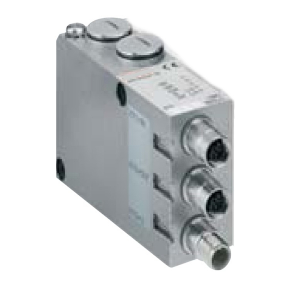
AVENTICS | EtherCAT | R412012792–BDL–001–AB Gerätebeschreibung 5.2 Gerätekomponenten 5.2.1 Buskoppler Abb. 2: Übersicht über den Buskoppler LED-Anzeigen für Diagnosemeldungen BTN-Beschriftungsfeld X71 (BUS IN) Anschluss für den Buskoppler zur Ansteuerung der Ventile X72 (BUS OUT) Anschluss für den Buskoppler X10 (POWER) Anschluss zur Spannungsversorgung der Elektronik und der... -
Page 16: Montage
AVENTICS | EtherCAT | R412012792–BDL–001–AB Montage Der Buskoppler ist ausschließlich für den Betrieb als Teilnehmer an einem EtherCAT-Bussegment bestimmt. EtherCAT-Adresse Zur Einstellung der EtherCAT-Adresse ist kein Schalter vorgesehen. Der Buskoppler unterstützt die automatische Adressvergabe der EtherCAT-Adresse. Übertragungsrate Die Übertragungsrate beträgt 100 MBits/s vollduplex. -
Page 17: Abmessungen
AVENTICS | EtherCAT | R412012792–BDL–001–AB Montage 6.1.1 Abmessungen A + 33 B + 33 Abb. 3: Maßzeichnung Ventilsystem (Buskoppler und Ventile) Die Maße A und B sind abhängig vom verwendeten Ventilblock. -
Page 18: Module Beschriften
AVENTICS | EtherCAT | R412012792–BDL–001–AB Montage 6.2 Module beschriften Buskoppler Beschriften Sie die für den Buskoppler vorgesehene/ verwendete Adresse am Buskoppler im Feld BTN. Für die Kennzeichnung der Steckanschlüsse sind im Gehäuse Einstecktaschen für Beschriftungsschilder (siehe „Ersatzteile und Zubehör“ auf Seite 40) vorhanden. -
Page 19: Buskoppler Elektrisch Anschließen
AVENTICS | EtherCAT | R412012792–BDL–001–AB Montage 6.3 Buskoppler elektrisch anschließen VORSICHT Anliegende elektrische Spannung Verletzungsgefahr durch elektrischen Schlag. O Schalten Sie immer den betreffenden Anlagenteil spannungsfrei und drucklos, bevor Sie am Ventilträger Module elektrisch anschließen. ACHTUNG Falsche Verkabelung Eine falsche oder fehlerhafte Verkabelung führt zu Fehlfunktionen und zur Beschädigung Bussystems. -
Page 20: Allgemeine Hinweise Zum Anschluss Des Buskopplers
AVENTICS | EtherCAT | R412012792–BDL–001–AB Montage ACHTUNG Stromfluss durch Potenzialunterschiede am Schirm Über den Schirm des EtherCAT-Kabels dürfen keine durch Potenzialunterschiede bedingten Ausgleichsströme fließen, da dadurch die Schirmung aufgehoben wird und die Leitung sowie der angeschlossene Buskoppler beschädigt werden können. -
Page 21: Buskoppler Als Zwischenstation Anschließen
AVENTICS | EtherCAT | R412012792–BDL–001–AB Montage 6.3.2 Buskoppler als Zwischenstation anschließen 1. Stellen Sie die korrekte Pin-Belegung Ihrer Steckerverbindungen her, wenn Sie keine konfektionierte Leitung verwenden (siehe Tabelle 5 auf Seite 20). 2. Schließen Sie die ankommende Busleitung an den Stecker X71 (BUS IN) an (1). -
Page 22: Logik- Und Lastversorgung Des Buskopplers Anschließen
AVENTICS | EtherCAT | R412012792–BDL–001–AB Montage Stellen Sie sicher, dass das Steckergehäuse fest mit dem Buskopplergehäuse verbunden ist. Ausgleichströme: Zur Vermeidung von Ausgleichsströmen über den Schirm des Buskopplers ist zwischen den Geräten eine Potenzialausgleichsleitung von mindestens 10 mm erforderlich. Buskabel: Das EtherCAT-Kabel muss mindestens die Anforderungen der Kategorie CAT5e erfüllen und... - Page 23 AVENTICS | EtherCAT | R412012792–BDL–001–AB Montage betätigten Ventilen oder 8 einseitig betätigten Ventilen) abgeschaltet werden. Die Zuordnung der Ventilgruppen (4 oder 8 Ventile) erfolgt über die Schiebeschalter S2 (siehe „Ventilversorgung auswählen“ auf Seite 27). Dadurch ist z. B. eine separate Abschaltung möglich.
-
Page 24: Fe-Anschluss
AVENTICS | EtherCAT | R412012792–BDL–001–AB Montage 2. Schließen Sie mit dem Steckerverbinder (siehe „Ersatzteile und Zubehör“ auf Seite 40) die Betriebsspannungen an den Buskoppler an. 3. Kontrollieren Sie die Spezifikationen der Betriebsspannungen anhand der elektrischen Kenngrößen und halten Sie diese ein (siehe Kapitel „Technische Daten“... -
Page 25: Inbetriebnahme Und Bedienung
AVENTICS | EtherCAT | R412012792–BDL–001–AB Inbetriebnahme und Bedienung Inbetriebnahme und Bedienung 7.1 Voreinstellungen vornehmen Folgende Voreinstellungen müssen Sie durchführen: Ventilversorgung auswählen Diagnosemeldungen einstellen Alle diese Einstellungen erfolgen über die Schalter unter den Verschraubungen A und B. Gehen Sie bei allen Voreinstellungen wie folgt vor: 1. - Page 26 AVENTICS | EtherCAT | R412012792–BDL–001–AB Inbetriebnahme und Bedienung Tabelle 8: S1, Überwachungsschwelle für Ventilspannung festlegen Schalter/ Diagnose Hinweise : Überlast, Ventiltreiber Diagnosemeldung, wenn ein Ventil ausgeschaltet Überlast bzw. Kurzschluss aufweist. Die Diagnosemeldung ist : Überlast, Ventiltreiber nur vorhanden, solange dieses eingeschaltet Ventil angesteuert ist.
-
Page 27: Umschalten Der Toleranzpegel Der Ventilversorgung U Und U
AVENTICS | EtherCAT | R412012792–BDL–001–AB Inbetriebnahme und Bedienung 7.1.2 Umschalten der Toleranzpegel der Ventilversorgung U und U Für die unterschiedlichen Ventilserien kann die Überwachungsschwelle zwischen 20,4 V und 21,6 V umgeschaltet werden (siehe 8 auf Seite 26). Im Auslieferungszustand ist die Schwelle auf 21,6 V (10 %) eingestellt (S1.7/1.8 auf OFF). - Page 28 AVENTICS | EtherCAT | R412012792–BDL–001–AB Inbetriebnahme und Bedienung Tabelle 9: Zuordnung der Schalter S2 Schieber Funktion Schalterstellung 1 Schalterstellung 2 Spannungsversorgung Ansteuerbyte 1 (externe Versorgung, (externe Versorgung, PIN 2, weiß) PIN 4, schwarz) Spannungsversorgung Ansteuerbyte 2 (externe Versorgung, (externe Versorgung, PIN 2, weiß)
- Page 29 AVENTICS | EtherCAT | R412012792–BDL–001–AB Inbetriebnahme und Bedienung Darin sind folgende Beispielkombinationen aufgeführt: Beispiele Verwendete Anschlussplatten Ventilbestückung Beispiel 1 Anschlussplatten für beidseitig beidseitig betätigte Ventile betätigte Ventile Beispiel 2 Anschlussplatten für beidseitig einseitig betätigte Ventile betätigte Ventile Beispiel 3 Anschlussplatten für beidseitig ein- und beidseitig betätigte...
- Page 30 AVENTICS | EtherCAT | R412012792–BDL–001–AB Inbetriebnahme und Bedienung Tabelle 10: Beispiele für die Zuordnung von Schaltern und Ventilversorgung, 32 Ventilspulen Beispiel 1 Beispiel 2 Beispiel 3 Anschlussplatte für beidseitig betätigte Ventile Ventil- Ventil- Ventil- Spule LED Spule LED Spule LED...
- Page 31 AVENTICS | EtherCAT | R412012792–BDL–001–AB Inbetriebnahme und Bedienung Tabelle 11: Beispiele für die Zuordnung von Schaltern und Ventilversorgung, 32 Ventilspulen Beispiel 4 Beispiel 5 Beispiel 6 Anschlussplatte für Anschlussplatte für ein- und beidseitig einseitig betätigte betätigte Ventile Ventile Ventil- Ventil-...
-
Page 32: Buskoppler Konfigurieren
AVENTICS | EtherCAT | R412012792–BDL–001–AB Inbetriebnahme und Bedienung 7.2 Buskoppler konfigurieren Die in diesem Abschnitt dargestellten Konfigurierungsschritte sind den bereits beschriebenen Einstellungen am Buskoppler (siehe „Voreinstellungen vornehmen“ auf Seite 25) übergeordnet und Teil der Busmasterkonfiguration des Gesamtsystems. Die beschriebenen Arbeiten dürfen nur von einer... -
Page 33: Test Und Diagnose Am Buskoppler
AVENTICS | EtherCAT | R412012792–BDL–001–AB Inbetriebnahme und Bedienung Das Betriebsverhalten, die relevanten Objekte und Parameter zur Konfiguration des Buskopplers, mögliche Einstellungen als Beispiele sowie der Funktionsumfang sind im Kapitel „Anhang Angaben zur Busmasterkonfiguration mit EtherCAT“ ab Seite 41 aufgeführt. 7.3 Test und Diagnose am Buskoppler 7.3.1 Diagnoseanzeige am Buskoppler ablesen... - Page 34 AVENTICS | EtherCAT | R412012792–BDL–001–AB Inbetriebnahme und Bedienung Tabelle 13: Bedeutung der General Purpose Inputs (GPI) GPI [...] Bedeutung der Bits Schalter S1.2 OPEN / CLOSE Schalter S1.3 OPEN / CLOSE Schalter S1.4 OPEN / CLOSE Schalter S1.5 OPEN / CLOSE Unterspannung (U <...
-
Page 35: Buskoppler In Betrieb Nehmen
AVENTICS | EtherCAT | R412012792–BDL–001–AB Inbetriebnahme und Bedienung 7.4 Buskoppler in Betrieb nehmen Bevor Sie das System in Betrieb nehmen, müssen Sie folgende Arbeiten durchgeführt und abgeschlossen haben: Sie haben den Ventilträger und den Buskoppler montiert (siehe „Buskoppler am VS montieren“ auf Seite 16). -
Page 36: Demontage Und Austausch
AVENTICS | EtherCAT | R412012792–BDL–001–AB Demontage und Austausch Demontage und Austausch Sie können je nach Bedarf den Buskoppler austauschen. Die Gewährleistung von AVENTICS gilt nur für die ausgelieferte Konfiguration und Erweiterungen, die bei der Konfiguration berücksichtigt wurden. Nach einem Umbau, der über diese Erweiterungen hinausgeht, erlischt die Gewährleistung. - Page 37 AVENTICS | EtherCAT | R412012792–BDL–001–AB Demontage und Austausch VORSICHT Anliegende elektrische Spannung und hoher Druck Verletzungsgefahr durch elektrischen Schlag und plötzlichen Druckabbau. O Schalten Sie das System drucklos und spannungsfrei. O Beachten Sie beim Umgang mit ESD-empfindlichen Baugruppen die vorgeschriebenen Vorsichtsmaßnahmen.
-
Page 38: Pflege Und Wartung
AVENTICS | EtherCAT | R412012792–BDL–001–AB Pflege und Wartung Pflege und Wartung VORSICHT Anliegende elektrische Spannung und hoher Druck! Verletzungsgefahr durch elektrischen Schlag und plötzlichen Druckabbau. O Schalten Sie das System vor der Durchführung von Pflege- und Wartungsarbeiten drucklos und spannungsfrei. -
Page 39: Technische Daten
AVENTICS | EtherCAT | R412012792–BDL–001–AB Technische Daten 10 Technische Daten 10.1 Kenngrößen Allgemein Schutzart nach EN 60 529 / IEC 529 IP65 im montierten Zustand Umgebungstemperatur 0 C bis +50 °C ohne Betauung Betrieb Lagerung –20 °C bis +70 °C Elektromagnetische Verträglichkeit... -
Page 40: Ersatzteile Und Zubehör
AVENTICS | EtherCAT | R412012792–BDL–001–AB Ersatzteile und Zubehör 11 Ersatzteile und Zubehör 11.1 Buskoppler Bestellnummer Buskoppler mit Feldbusprotokoll EtherCAT R412009573 mit Ansteuerung für 32 Ventilspulen Zubehör Satz: Dichtung, 2 Schrauben M4, 1 Schraube FE R412008885 10x Verschlussschraube, metrisch R412008886 5x Karten-Einsteckschilder... -
Page 41: Anhang
AVENTICS | EtherCAT | R412012792–BDL–001–AB Anhang 13 Anhang 13.1 Angaben zur Busmasterkonfiguration mit EtherCAT Beim Buskoppler handelt es sich um ein Ausgangsmodul mit festeingestellten 32 digitalen Ausgängen. Zur Konfiguration und Administration sind daher nur wenige Schritte notwendig. 13.2 Betriebsverhalten Pro Anschaltung können 4 Byte Master-Echtzeit-Daten (Ausgänge) verarbeitet werden. -
Page 42: Konfigurationsdatei
AVENTICS | EtherCAT | R412012792–BDL–001–AB Anhang 13.4 Konfigurationsdatei Die Datei ist eine von der EtherCAT Technology Group (ETG) spezifizierte ASCII-Datei im Extensible-Markup- Language-Format (XML), in der die Objekte/ Leistungsmerkmale eines EtherCAT-Geräts beschrieben sind. Für den Buskoppler gibt es diese Datei mit dem Dateinamen BDC_ECAT32.XML. -
Page 43: Stichwortverzeichnis
AVENTICS | EtherCAT | R412012792–BDL–001–AB Stichwortverzeichnis Stichwortverzeichnis Diagnoseanzeige 33 Abkürzungen 7 Voreinstellungen 25 Baudrate einstellen 25 Kenngrößen 39 Beschriftung Komponenten Modul 18 Buskoppler 15 Betriebsverhalten, Konfiguration, Busmaster 41 Busanschaltung 41 Konfigurationsdatei 42 Buskoppler Aufbau 15 austauschen 36 Mode-Schalter 25 Ersatzteile, Zubehör 40... - Page 44 AVENTICS | EtherCAT | R412012792–BDL–001–AB Stichwortverzeichnis Warnhinweise, Definitionen 6 Zubehör 40...
- Page 45 AVENTICS | EtherCAT | R412012792–BDL–001–AB Contents Contents About this documentation ......47 Documentation validity .........47 Required and supplementary documentation ..47 Presentation of information ........ 47 1.3.1 Safety instructions ..........48 1.3.2 Symbols ..............48 1.3.3 Abbreviations ............49 Safety instructions ........50 About this chapter ..........
- Page 46 AVENTICS | EtherCAT | R412012792–BDL–001–AB Contents Commissioning and operation ..... 65 Making settings ............65 7.1.1 Setting diagnostic messages ......66 7.1.2 Switching the tolerance level for U valve supply ............ 68 7.1.3 Selecting the valve supply ......... 68 Configuring the bus coupler ........ 74 Testing and diagnosis on the bus coupler ..75...
-
Page 47: About This Documentation
AVENTICS | EtherCAT | R412012792–BDL–001–AB About this documentation About this documentation 1.1 Documentation validity This documentation contains important information on the safe and appropriate assembly, operation, and maintenance of the bus coupler and how to remedy simple malfunctions yourself. Read this documentation completely, especially chapter “Safety instructions”, before working with the... -
Page 48: Safety Instructions
AVENTICS | EtherCAT | R412012792–BDL–001–AB About this documentation 1.3.1 Safety instructions This documentation contains safety instructions before any steps that involve a risk of personal injury or damage to property. The measures described to avoid these hazards must be observed. -
Page 49: Abbreviations
AVENTICS | EtherCAT | R412012792–BDL–001–AB About this documentation Table 3: Meaning of the symbols Symbol Meaning If this information is disregarded, the product cannot be used or operated optimally. Individual, independent action Numbered steps: The numbers indicate sequential steps. 1.3.3 Abbreviations... -
Page 50: Safety Instructions
AVENTICS | EtherCAT | R412012792–BDL–001–AB Safety instructions Safety instructions 2.1 About this chapter The product has been manufactured according to the accepted rules of safety and current technology. There is, however, still a danger of personal injury or damage to... -
Page 51: Personnel Qualifications
AVENTICS | EtherCAT | R412012792–BDL–001–AB Safety instructions AVENTICS GmbH is not liable for any damages resulting from improper use. The user alone bears the risks of improper use of the product. Improper use of the bus coupler includes: use for any application not stated in these... -
Page 52: Safety Instructions Related To The Product And Technology
You may only commission the product if you have determined that the end product (such as a machine or system) in which the AVENTICS products are installed meets the country-specific provisions, safety regulations, and standards for the specific application. -
Page 53: Applications
AVENTICS | EtherCAT | R412012792–BDL–001–AB Applications On installation Always make sure the relevant system component is not under pressure or voltage before assembly or disassembly. Ensure that the system is prevented from power restoration during assembly work. Ground the modules and valve system. Observe the following standards when installing the system: –... -
Page 54: Delivery Contents
1 bus coupler with seal and 2 mounting screws 1 set of operating instructions for the bus coupler The VS is individually configured. You can find the exact configuration in the AVENTICS Internet configurator under your order number. Device description The bus coupler allows you to control the VS via the real- time Ethernet technology EtherCAT. -
Page 55: Total Overview Of The Valve System
AVENTICS | EtherCAT | R412012792–BDL–001–AB Device description 5.1 Total overview of the valve system The valve system consists of the following parts as illustrated in Fig. 1 (depending on the order): Fig. 1: Overview: bus coupler sample configuration with assembled VS... -
Page 56: Device Components
AVENTICS | EtherCAT | R412012792–BDL–001–AB Device description 5.2 Device components 5.2.1 Bus coupler Fig. 2: Bus coupler overview LED displays for diagnostic messages Bus slave label X71 (BUS IN) connection for the bus coupler to control the valves X72 connection (BUS OUT) for the bus coupler... -
Page 57: Assembly
AVENTICS | EtherCAT | R412012792–BDL–001–AB Assembly The bus coupler is designed only for use as a participant in an EtherCat bus segment. EtherCAT address A switch is not required to set the EtherCAT address. The bus coupler supports automatic address assignment of the EtherCAT address. -
Page 58: Dimensions
AVENTICS | EtherCAT | R412012792–BDL–001–AB Assembly The dimensions of the complete VS vary according to module equipment (see Fig. 3). 6.1.1 Dimensions A + 33 B + 33 Fig. 3: Dimensioned drawing of the valve system (bus coupler and valves) Dimensions A and B depend on the valve block used. -
Page 59: Connecting The Bus Coupler Electrically
AVENTICS | EtherCAT | R412012792–BDL–001–AB Assembly Fig. 4: Label areas on the bus coupler 6.3 Connecting the bus coupler electrically CAUTION Applied electric voltage Danger of injury from electric shock O Make sure the relevant system component is not under pressure or connected to power when electrically connecting modules to the valve terminal. -
Page 60: General Notes On Connecting The Bus Coupler
AVENTICS | EtherCAT | R412012792–BDL–001–AB Assembly NOTICE Faulty wiring Faulty wiring can lead to malfunctions as well as damage to the bus system. O Unless otherwise stipulated, comply with the EtherCAT Technology Group (ETG) construction and design directives. O Only use cables that meet the Ethernet specifications as well as the connection speed and length requirements. -
Page 61: Connecting The Bus Coupler As An Intermediate Station
AVENTICS | EtherCAT | R412012792–BDL–001–AB Assembly Table 5: Assignment X71 (BUS IN) and X72 BUS IN (BUS OUT), M12, D-coded Signal Meaning Transmit pos. Receive pos. TD– Transmit neg. RD– Receive neg. BUS OUT Housing Shield or functional grounding X71/X72: communication connection... -
Page 62: Connecting The Bus Coupler As A Final Station
AVENTICS | EtherCAT | R412012792–BDL–001–AB Assembly 6.3.3 Connecting the bus coupler as a final station 1. Set up the correct pin assignment (see Tab. 5 on page 61) on the plug connections if you do not use pre-assembled cables. 2. Connect the incoming bus connection to the X71 (BUS IN) plug (1). - Page 63 AVENTICS | EtherCAT | R412012792–BDL–001–AB Assembly Table 6: Assignment of the X10 plug (POWER), M12, POWER A-coded Assignment Bus coupler logic power supply Valve power supply Ground for U and U Valve power supply The power supply (pin 1) must be protected by an external fuse (500 mA, F).
-
Page 64: Fe Connection
AVENTICS | EtherCAT | R412012792–BDL–001–AB Assembly CAUTION Dangerous voltages A power pack without safe isolation may lead to dangerous voltages in the event of a malfunction. Injuries from electric shock and system damage may be the consequences. O Only use a power pack with safe isolation according... -
Page 65: Commissioning And Operation
AVENTICS | EtherCAT | R412012792–BDL–001–AB Commissioning and operation Fig. 5: FE connection on the bus coupler (1) Commissioning and operation 7.1 Making settings The following presettings need to be made: Selecting the valve supply Setting the diagnostic messages All of these settings are made using the switch beneath fittings A and B. -
Page 66: Setting Diagnostic Messages
AVENTICS | EtherCAT | R412012792–BDL–001–AB Commissioning and operation 7.1.1 Setting diagnostic messages The S1 mode switch used to set the diagnostic messages S1.1 is located under fitting A. S1.5 The system is EtherCAT conform on delivery. Diagnosis is deactivated (S1.1 set to OFF). - Page 67 AVENTICS | EtherCAT | R412012792–BDL–001–AB Commissioning and operation Table 8: S1, defining the monitoring threshold for valve voltage Switch/bit Diagnosis Notes : Overload, This diagnostic message is valve driver switched off displayed if a valve reports an overload or short circuit. The...
-
Page 68: Switching The Tolerance Level For U Q1 And
AVENTICS | EtherCAT | R412012792–BDL–001–AB Commissioning and operation 7.1.2 Switching the tolerance level for U valve supply The monitoring threshold can be switched between 20.4 V and 21.6 V for the various valve series (see Tab. 8 on page 67). On delivery, the threshold is set to 21.6 V (10%) (S1.7/1.8 set to OFF). - Page 69 AVENTICS | EtherCAT | R412012792–BDL–001–AB Commissioning and operation Table 9: S2 switch assignment Slider Function Switch position 1 Switch position 2 Power supply control byte 1 (external supply, PIN 2, (external supply, PIN 4, white) black) Power supply control byte 2...
- Page 70 AVENTICS | EtherCAT | R412012792–BDL–001–AB Commissioning and operation Examples for assignment of switch S4 and the supply of assembled valves for 32 valve solenoids can be found in Tab. 10 and Tab. 11 on pages 71 and 72 (examples 1 to 3/ examples 4 to 6, respectively).
- Page 71 AVENTICS | EtherCAT | R412012792–BDL–001–AB Commissioning and operation Table 10: Examples for assignment of switches and valve supply, 32 valve coils Example 1 Example 2 Example 3 Subbase for double solenoid valves Valve Solenoid Valve Solenoid Valve Solenoid position position position S2.1...
- Page 72 AVENTICS | EtherCAT | R412012792–BDL–001–AB Commissioning and operation Table 10: Examples for assignment of switches and valve supply, 32 valve coils Example 1 Example 2 Example 3 Subbase for double solenoid valves Valve Solenoid Valve Solenoid Valve Solenoid position position position S2.4...
- Page 73 AVENTICS | EtherCAT | R412012792–BDL–001–AB Commissioning and operation Table 11: Examples for assignment of switches and valve supply, 32 valve coils Example 4 Example 5 Example 6 Subbase for single Subbase for single and double solenoid solenoid valves valves Valve...
-
Page 74: Configuring The Bus Coupler
AVENTICS | EtherCAT | R412012792–BDL–001–AB Commissioning and operation 7.2 Configuring the bus coupler The configuration steps laid out in this section are superior to the settings on the bus coupler which have already been described (see “Making settings” on page 65) and are a part of the entire system's bus master configuration. -
Page 75: Testing And Diagnosis On The Bus Coupler
AVENTICS | EtherCAT | R412012792–BDL–001–AB Commissioning and operation The operating behavior, relevant objects and parameters to configure the bus coupler, possible setting examples, and scope of function are listed in the chapter “Information on the bus master configuration with EtherCAT” from page 84. - Page 76 AVENTICS | EtherCAT | R412012792–BDL–001–AB Commissioning and operation Table 12: Definitions for diagnostic LEDs on the bus coupler Signal Description L1/A1 Green, flashing quickly Connection (“link”) and data exchange (“activity”) with a participant at plug X72 Green Connection (“link”) to a participant at plug X72 No connection (“link”) to a participant at plug X72...
-
Page 77: Commissioning The Bus Coupler
AVENTICS | EtherCAT | R412012792–BDL–001–AB Commissioning and operation Table 13: Meaning of the General Purpose Inputs (GPI) GPI [...] Meaning of the bits Switch S1.3 CLOSE and valve supply U < 12 V Valve supply U > 12 V Switch S1.2 CLOSE and valve supply U <... -
Page 78: Disassembly/Exchange
3. Switch on the compressed air supply. Disassembly/exchange You can exchange the bus coupler, if needed. The AVENTICS warranty only applies to the delivered configuration and extensions taken into account in the configuration. The warranty no longer applies after a conversion that exceeds these extensions. -
Page 79: Exchanging The Bus Coupler
AVENTICS | EtherCAT | R412012792–BDL–001–AB Disassembly/exchange 8.1 Exchanging the bus coupler Fig. 6: Exchanging the bus coupler, example Hexagonal socket-head screws M4x35 Bus coupler Seal VS EP end plate... - Page 80 AVENTICS | EtherCAT | R412012792–BDL–001–AB Disassembly/exchange CAUTION Applied electric voltage and high pressure! Danger of injury from electric shocks and sudden pressure drops. O Turn off the operating voltage and compressed air supply. O Observe the stipulated precautionary measures when working with ESD-sensitive assemblies.
-
Page 81: Service And Maintenance
AVENTICS | EtherCAT | R412012792–BDL–001–AB Service and maintenance Service and maintenance CAUTION Applied electric voltage and high pressure! Danger of injury from electric shocks and sudden pressure drops. O Make sure the system is not pressurized or connected to power before carrying out any service or maintenance work. -
Page 82: Technical Data
AVENTICS | EtherCAT | R412012792–BDL–001–AB Technical data 10 Technical data 10.1 Characteristics General Protection class according to EN 60529/IEC 529 IP65 when assembled Ambient temperature Operation 0°C to +50°C, without condensation Storage –20°C to +70°C Electromagnetic compatibility Interference immunity... -
Page 83: Spare Parts And Accessories
AVENTICS | EtherCAT | R412012792–BDL–001–AB Spare parts and accessories 11 Spare parts and accessories 11.1 Bus coupler Order number Bus coupler with fieldbus protocol EtherCAT with control for R412009573 32 valve solenoids Accessories Set: Seal, 2 screws M4, 1 screw FE... -
Page 84: Appendix
AVENTICS | EtherCAT | R412012792–BDL–001–AB Appendix 13 Appendix 13.1 Information on the bus master configuration with EtherCAT The bus coupler is an output module with 32 permanently set digital outputs. As a result, very few steps are required for configuration and administration. -
Page 85: Index
AVENTICS | EtherCAT | R412012792–BDL–001–AB Index Index Abbreviations 49 Electrical connection Accessories 83 Bus coupler as final station 62 Assembly Bus coupler as intermediate Assembly options 57 station 61 FE connection 64 FE 64 Logic and load supply 62 Shielding 61... - Page 86 AVENTICS | EtherCAT | R412012792–BDL–001–AB Index Safety instructions, definitions 48 Selecting the valve supply 68 Setting the baud rate 66 Spare Parts 83 Standards 53 Switch S2 68 Test and diagnosis Bus coupler 75 Improper 50 Intended 50...
- Page 87 AVENTICS | EtherCAT | R412012792–BDL–001–AB Sommaire Sommaire A propos de cette documentation ....89 Validité de la documentation....... 89 Documentations nécessaires et complémentaires............ 89 Présentation des informations......89 1.3.1 Consignes de sécurité ......... 90 1.3.2 Symboles ..............90 1.3.3 Abréviations ............91 Consignes de sécurité...
- Page 88 AVENTICS | EtherCAT | R412012792–BDL–001–AB Sommaire Mise en service et utilisation ..... 109 Effectuer les paramétrages préalables..109 7.1.1 Réglage des notifications de diagnostic ..109 7.1.2 Commuter le niveau de tolérance de l’alimentation des distributeurs U et U 7.1.3 Sélectionner l’alimentation des distributeurs 111 Configuration du coupleur de bus ....116...
-
Page 89: Propos De Cette Documentation
AVENTICS | EtherCAT | R412012792–BDL–001–AB A propos de cette documentation A propos de cette documentation 1.1 Validité de la documentation Cette documentation contient des informations importantes pour installer, utiliser et entretenir le produit de manière sûre et conforme, ainsi que pour pouvoir éliminer soi-même de simples interférences. -
Page 90: Consignes De Sécurité
AVENTICS | EtherCAT | R412012792–BDL–001–AB A propos de cette documentation 1.3.1 Consignes de sécurité Dans la présente documentation, des consignes de sécurité figurent devant les instructions dont l’exécution recèle un risque de dommages corporels ou matériels. Les mesures décrites pour éviter des dangers doivent être respectées. -
Page 91: Abréviations
AVENTICS | EtherCAT | R412012792–BDL–001–AB A propos de cette documentation Tableau 3 : Signification des symboles Symbole Signification En cas de non-respect de cette information, le produit ne livrera pas sa performance optimale. Action isolée et indépendante Consignes numérotées : Les chiffres indiquent l’ordre des... -
Page 92: Consignes De Sécurité
AVENTICS | EtherCAT | R412012792–BDL–001–AB Consignes de sécurité Consignes de sécurité 2.1 A propos de ce chapitre Le produit a été fabriqué selon les règles techniques généralement reconnues. Des dommages matériels et corporels peuvent néanmoins survenir si ce chapitre de même que les consignes de sécurité... -
Page 93: Utilisation Non Conforme
(sécurité fonctionnelle). AVENTICS GmbH décline toute responsabilité en cas de dommages résultant d’une utilisation non conforme. Toute utilisation non conforme est aux risques et périls de l’utilisateur. -
Page 94: Consignes Générales De Sécurité
état technique est irréprochable. Respecter toutes les consignes concernant le produit. Les personnes montant, commandant, démontant ou entretenant des produits AVENTICS, ne doivent pas être sous l’emprise d’alcool, de drogues ou de médicaments divers pouvant altérer leur temps de réaction. -
Page 95: Consignes De Sécurité Selon Le Produit Et La Technique
AVENTICS | EtherCAT | R412012792–BDL–001–AB Consignes de sécurité 2.6 Consignes de sécurité selon le produit et la technique En règle générale ne pas modifier ni transformer l’appareil. Utiliser l’appareil uniquement dans le champ de travail indiqué dans les données techniques. -
Page 96: Domaines D'application
AVENTICS | EtherCAT | R412012792–BDL–001–AB Domaines d’application Lors de la L’installation ne doit avoir lieu qu’en l’absence de mise en service toute tension et de toute pression et n’être effectuée que par du personnel qualifié et expérimenté. N’effectuer la mise en service électrique qu’en l’absence de toute pression afin d’éviter tout... -
Page 97: Fourniture
AVENTICS | EtherCAT | R412012792–BDL–001–AB Fourniture Fourniture La fourniture d’un système de distributeurs configuré comprend : 1 système de distributeurs conformément à la configuration et à la commande 1 mode d’emploi du système de distributeurs 1 mode d’emploi du coupleur de bus La fourniture d’un jeu de pièces pour un coupleur de bus... -
Page 98: Vue D'ensemble Du Système De Distributeurs
AVENTICS | EtherCAT | R412012792–BDL–001–AB Description de l’appareil 5.1 Vue d’ensemble du système de distributeurs Selon la commande, le système de distributeurs est constitué des composants représentés à la fig. 1 : Fig. 1 : Vue d’ensemble : exemple de configuration de coupleur de bus avec VS monté... -
Page 99: Composants
AVENTICS | EtherCAT | R412012792–BDL–001–AB Description de l’appareil 5.2 Composants 5.2.1 Coupleur de bus Fig. 2 : Vue d’ensemble du coupleur de bus Affichages LED pour notifications de diagnostic Case d’inscription BTN Raccord X71 (BUS IN) pour le coupleur de bus pour la commande des distributeurs Raccord X72 (BUS OUT) pour le coupleur de bus Raccord X10 (POWER) pour l’alimentation en tension du système électronique et des... - Page 100 100 AVENTICS | EtherCAT | R412012792–BDL–001–AB Description de l’appareil Le coupleur de bus est exclusivement destiné au fonctionnement en tant que participant d’un segment bus EtherCAT. Adresse EtherCAT Aucun interrupteur n’est prévu pour le réglage de l’adresse EtherCAT. Le coupleur de bus reconnaît l’attribution automatique de l’adresse EtherCAT.
-
Page 101: Montage
AVENTICS | EtherCAT | R412012792–BDL–001–AB 101 Montage Montage 6.1 Montage du coupleur de bus sur le système de distributeurs Le système de distributeurs est livré individuellement configuré, complètement vissé avec tous les composants : Porte-distributeurs Coupleur de bus Le montage de l’ensemble du système de distributeurs est décrit précisément dans le mode d’emploi ci-joint... -
Page 102: Marquage Des Modules
102 AVENTICS | EtherCAT | R412012792–BDL–001–AB Montage Les mesures A et B dépendent du bloc de distributeurs employé. 6.2 Marquage des modules Coupleur de bus Inscrire l’adresse prévue/utilisée pour le coupleur de bus dans le champ BTN sur le coupleur de bus. -
Page 103: Raccordement Électrique Du Coupleur De Bus103
AVENTICS | EtherCAT | R412012792–BDL–001–AB 103 Montage 6.3 Raccordement électrique du coupleur de bus ATTENTION Tension électrique présente Risque de blessure par décharge électrique. O Toujours mettre la partie concernée de l’installation hors tension et hors pression, avant de procéder au raccordement électrique des modules sur le porte-... -
Page 104: Remarques Générales Concernant Le Raccordement Du Coupleur De Bus
104 AVENTICS | EtherCAT | R412012792–BDL–001–AB Montage REMARQUE Flux de courant via des différences de potentiel au niveau de l’écran Aucun courant compensateur, dû à des différences de potentiel, ne doit passer via le blindage du câble EtherCAT, car le blindage est ainsi supprimé et les câbles ainsi que le coupleur de bus branché... -
Page 105: Raccorder Le Coupleur De Bus En Tant Que Station Intermédiaire
AVENTICS | EtherCAT | R412012792–BDL–001–AB 105 Montage La technique de raccordement et l’affectation des connecteurs correspondent aux prévisions de la directive technique. 6.3.2 Raccorder le coupleur de bus en tant que station intermédiaire 1. Si vous n’utilisez pas de câbles confectionnés, effectuer l’affectation correcte des broches (voir... -
Page 106: Raccordement De L'alimentation Des Circuits Logiques Et Des Distributeurs Du Coupleur De Bus
106 AVENTICS | EtherCAT | R412012792–BDL–001–AB Montage permet de protéger les câbles de données contre les parasites. S’assurer que le boîtier du connecteur est solidement connecté au boîtier du coupleur de bus. Courants compensateurs : pour éviter que des courants compensateurs passent via le blindage du coupleur de bus, un câble de... - Page 107 AVENTICS | EtherCAT | R412012792–BDL–001–AB 107 Montage et U sont reliés entre eux de façon galvanique. Les distributeurs peuvent être arrêtés par octet (correspond à 4 distributeurs bistables ou 8 distributeurs monostables) par le biais de l’alimentation de distributeur U et U L’affectation des groupes de distributeurs (4 ou 8...
-
Page 108: Raccord Fe
108 AVENTICS | EtherCAT | R412012792–BDL–001–AB Montage Pour raccorder l’alimentation des distributeurs du coupleur de bus, procéder comme suit : 1. En cas d’utilisation de câbles non confectionnés, effectuer l’affectation correcte des broches (voir Tab. 6 à la page 106) des raccords enfichables. -
Page 109: Mise En Service Et Utilisation
AVENTICS | EtherCAT | R412012792–BDL–001–AB 109 Mise en service et utilisation Mise en service et utilisation 7.1 Effectuer les paramétrages préalables Effectuer les paramétrages préalables ci-après : Sélectionner l’alimentation des distributeurs Paramétrer les notifications de diagnostic Tous ces paramétrages s’effectuent par l’intermédiaire des commutateurs situés sous les deux vissages A et B. - Page 110 110 AVENTICS | EtherCAT | R412012792–BDL–001–AB Mise en service et utilisation Tableau 8 : S1, définir le seuil de contrôle pour la tension de distributeur Commutateur / Diagnostic Remarques : surcharge, Notification de diagnostic si un pilote déconnecté distributeur présente une surcharge ou un court-circuit.
-
Page 111: Commuter Le Niveau De Tolérance De L'alimentation Des Distributeurs U Q1 Et U Q2
AVENTICS | EtherCAT | R412012792–BDL–001–AB 111 Mise en service et utilisation 7.1.2 Commuter le niveau de tolérance de l’alimentation des distributeurs U et U Pour les différentes séries de distributeurs, il est possible de commuter entre 20,4 V et 21,6 V pour le seuil de contrôle (voir tab. - Page 112 112 AVENTICS | EtherCAT | R412012792–BDL–001–AB Mise en service et utilisation Tableau 9 : Affectation des commutateurs S2 Position de Position de Tiroir Fonction commutateur 1 commutateur 2 Alimentation en tension octet de commande 1 (alimentation externe, (alimentation externe, broche 2, fil blanc)
- Page 113 AVENTICS | EtherCAT | R412012792–BDL–001–AB 113 Mise en service et utilisation Les combinaisons suivantes y sont représentées : Exemples Embases utilisées Equipement des distributeurs Exemple 1 Embases pour les distributeurs Distributeurs bistables bistables Exemple 2 Embases pour les distributeurs Distributeurs monostables...
- Page 114 114 AVENTICS | EtherCAT | R412012792–BDL–001–AB Mise en service et utilisation Tableau 10 : Exemples pour l’affectation de commutateurs et l’alimentation des distributeurs, 32 bobines de distributeur Exemple 1 Exemple 2 Exemple 3 Embase de raccordement pour distributeurs bistables Empl.
- Page 115 AVENTICS | EtherCAT | R412012792–BDL–001–AB 115 Mise en service et utilisation Tableau 11 : Exemples pour l’affectation de commutateurs et l’alimentation des distributeurs, 32 bobines de distributeur Exemple 4 Exemple 5 Exemple 6 Embase de raccordement Embase pour distributeurs pour distributeurs...
-
Page 116: Configuration Du Coupleur De Bus
116 AVENTICS | EtherCAT | R412012792–BDL–001–AB Mise en service et utilisation 7.2 Configuration du coupleur de bus Les étapes de configuration présentées dans ce chapitre prévalent sur les paramétrages déjà décrits effectués sur le coupleur de bus (voir « Effectuer les paramétrages préalables »... - Page 117 AVENTICS | EtherCAT | R412012792–BDL–001–AB 117 Mise en service et utilisation Le comportement en service, les objets importants et les paramètres pour la configuration du coupleur de bus, ainsi que des exemples de paramétrage et l’étendue des fonctions sont indiqués dans le chapitre «...
-
Page 118: Test Et Diagnostic Du Coupleur De Bus
118 AVENTICS | EtherCAT | R412012792–BDL–001–AB Mise en service et utilisation 7.3 Test et diagnostic du coupleur de bus 7.3.1 Lecture de l’affichage de diagnostics sur le coupleur de bus Les LED sur la plaque frontale du coupleur de bus restituent les messages indiqués dans le tableau 12. - Page 119 AVENTICS | EtherCAT | R412012792–BDL–001–AB 119 Mise en service et utilisation Tableau 13 : Signification des GPI (General Purpose Inputs) GPI [...] Signification des bits Commutateur S1.2 OPEN / CLOSE Commutateur S1.3 OPEN / CLOSE Commutateur S1.4 OPEN / CLOSE Commutateur S1.5 OPEN / CLOSE...
-
Page 120: Mise En Service Du Coupleur De Bus
120 AVENTICS | EtherCAT | R412012792–BDL–001–AB Mise en service et utilisation 7.4 Mise en service du coupleur de bus Avant de mettre le système en service, il convient d’effectuer et de clôturer les travaux suivants : Monter le porte-distributeurs et le coupleur de bus (voir «... -
Page 121: Démontage Et Remplacement
Démontage et remplacement Si nécessaire, il est possible de remplacer le coupleur de bus. La garantie d’AVENTICS n’est valable que pour la configuration livrée et les extensions ayant été prises en compte lors de celle-ci. Après une transformation dépassant ces extensions, la garantie n’est plus valable. - Page 122 122 AVENTICS | EtherCAT | R412012792–BDL–001–AB Démontage et remplacement ATTENTION Tension électrique et pression importante Risque de blessures par choc électrique et chute de pression subite. O Mettre le système hors pression et hors tension. O Respecter les mesures de précaution prescrites dans le maniement de modules sensibles aux décharges électrostatiques.
-
Page 123: Nettoyage Et Entretien
AVENTICS | EtherCAT | R412012792–BDL–001–AB 123 Nettoyage et entretien Nettoyage et entretien ATTENTION Tension électrique et pression importante ! Risque de blessures par choc électrique et chute de pression subite. O Avant de réaliser des travaux d’entretien et de maintenance, mettre le système hors pression et hors tension. -
Page 124: Données Techniques
124 AVENTICS | EtherCAT | R412012792–BDL–001–AB Données techniques 10 Données techniques 10.1 Caractéristiques Généralités Indice de protection selon la norme IP 65 en état monté EN 60529 / IEC 529 Température ambiante Fonctionnement De 0 °C à + +50 °C sans condensation Stockage de –... -
Page 125: Pièces De Rechange Et Accessoires
AVENTICS | EtherCAT | R412012792–BDL–001–AB 125 Pièces de rechange et accessoires 11 Pièces de rechange et accessoires 11.1 Coupleur de bus N° de référence Coupleur de bus avec protocole bus de terrain EtherCAT R412009573 avec commande pour 32 bobines de distributeur... -
Page 126: Annexe
126 AVENTICS | EtherCAT | R412012792–BDL–001–AB Annexe 13 Annexe 13.1 Indications concernant la configuration du maître bus avec EtherCAT Le coupleur de bus est un module de sortie composé de 32 sorties numériques à réglage fixe. Par conséquent, la configuration et l’administration ne nécessitent que quelques réglages. - Page 127 AVENTICS | EtherCAT | R412012792–BDL–001–AB 127 Index Index Abréviations 91 Marquage Accessoires 125 Module 102 Affichage de diagnostic, Mise en service Coupleur de bus 118 Affichage de diagnostics 118 Mise en service 120 Paramétrages préalables 109 Montage Caractéristiques 124 Possibilités de montage 101...
-
Page 128: Index
128 AVENTICS | EtherCAT | R412012792–BDL–001–AB Index Sélectionner l’alimentation des distributeurs 111 Test et diagnostic Coupleur de bus 118 Utilisation Conforme 92 Non conforme 93... - Page 129 AVENTICS | EtherCAT | R412012792–BDL–001–AB 129 Indice Indice Sulla presente documentazione ....131 Validità della documentazione ......131 Documentazione necessaria e complementare ..........131 Rappresentazione delle informazioni ....132 1.3.1 Indicazioni di sicurezza ........132 1.3.2 Simboli ..............133 1.3.3 Abbreviazioni ............133 Indicazioni di sicurezza ......
- Page 130 130 AVENTICS | EtherCAT | R412012792–BDL–001–AB Indice Messa in funzione e comando ....151 Esecuzione delle preimpostazioni....151 7.1.1 Impostazione delle segnalazioni diagnostiche ............151 7.1.2 Commutazione del livello di tolleranza dell'alimentazione della valvola U 7.1.3 Selezione dell’alimentazione valvole ..153 Configurazione dell'accoppiatore bus ....160...
-
Page 131: Sulla Presente Documentazione
AVENTICS | EtherCAT | R412012792–BDL–001–AB 131 Sulla presente documentazione Sulla presente documentazione 1.1 Validità della documentazione La presente documentazione contiene importanti informazioni per installare gli accoppiatori bus in modo sicuro e corretto, metterli in funzione, azionarli, per sottoporli a manutenzione e per riparare autonomamente piccoli guasti. -
Page 132: Rappresentazione Delle Informazioni
132 AVENTICS | EtherCAT | R412012792–BDL–001–AB Sulla presente documentazione 1.3 Rappresentazione delle informazioni Per consentire un impiego rapido e sicuro del prodotto, all’interno della presente documentazione vengono utilizzati avvertenze di sicurezza, simboli, termini e abbreviazioni unitari. Per una migliore comprensione questi sono illustrati nei seguenti paragrafi. -
Page 133: Simboli
AVENTICS | EtherCAT | R412012792–BDL–001–AB 133 Sulla presente documentazione Tabella 2: Classi di pericolo secondo ANSI Z535.6-2006 Segnale di avvertimento, Significato parola di segnalazione Indica una situazione pericolosa che, se non ATTENZIONE evitata, può provocare lesioni medie o leggere Danni materiali: il prodotto o l’ambiente NOTA circostante possono essere danneggiati. -
Page 134: Indicazioni Di Sicurezza
134 AVENTICS | EtherCAT | R412012792–BDL–001–AB Indicazioni di sicurezza Tabella 4: Abbreviazioni Abbreviazione Significato EtherCAT Technology Group General Purpose Input GPIO General Purpose Input Output General Purpose Output INIT Mode Modalità di inizializzazione Piastra terminale P Piastra terminale con attacchi pneumatici... -
Page 135: Utilizzo A Norma
(sicurezza funzionale). In caso di danni per uso non a norma decade qualsiasi responsabilità di AVENTICS GmbH. I rischi in caso di uso non a norma sono interamente a carico dell’utente. Per utilizzo non a norma del prodotto si intende: l’uso al di fuori degli ambiti d’applicazione riportati in... -
Page 136: Qualifica Del Personale
136 AVENTICS | EtherCAT | R412012792–BDL–001–AB Indicazioni di sicurezza 2.4 Qualifica del personale Le attività descritte nella presente documentazione richiedono conoscenze di base in ambito elettrico e pneumatico e conoscenze dei termini specifici appartenenti a questi campi. Per garantire la sicurezza operativa, queste attività... -
Page 137: Avvertenze Di Sicurezza Sul Prodotto E Sulla Tecnologia
Mettere in funzione il prodotto solo dopo aver stabilito che il prodotto finale (per esempio una macchina o un impianto) in cui i prodotti AVENTICS sono installati corrisponde alle disposizioni nazionali vigenti, alle disposizioni sulla sicurezza e alle norme dell’applicazione. -
Page 138: Campi Di Impiego
138 AVENTICS | EtherCAT | R412012792–BDL–001–AB Campi di impiego Mettere a terra i moduli e il sistema di valvole. Osservare le seguenti norme nell’installazione del sistema: – DIN EN 50178, classificazione VDE 0160 – VDE 0100 Durante la L’installazione deve essere eseguita soltanto dopo messa in funzione aver tolto l’alimentazione elettrica e pneumatica e... -
Page 139: Fornitura
AVENTICS | EtherCAT | R412012792–BDL–001–AB 139 Fornitura Fornitura Sono compresi nella fornitura di un sistema di valvole configurato: 1 sistema di valvole come da configurazione e ordinazione 1 istruzioni per l’uso della sistema di valvole 1 istruzioni per l'uso per l'accoppiatore bus... -
Page 140: Panoramica Sistema Di Valvole
140 AVENTICS | EtherCAT | R412012792–BDL–001–AB Descrizione dell’apparecchio 5.1 Panoramica sistema di valvole Il sistema di valvole è costituito, a seconda della fornitura, dai componenti rappresentati nella Fig. 1: Fig. 1: Panoramica: esempio di configurazione accoppiatore bus con sistema di... -
Page 141: Componenti Dell'apparecchio
AVENTICS | EtherCAT | R412012792–BDL–001–AB 141 Descrizione dell’apparecchio 5.2 Componenti dell’apparecchio 5.2.1 Accoppiatore bus Fig. 2: Panoramica accoppiatore bus Indicatori LED per segnalazioni diagnostiche Campo di dicitura partecipanti al bus (BTN) Attacco X71 (BUS IN) per accoppiatore bus per il pilotaggio delle valvole Attacco X72 (BUS OUT) per accoppiatore bus Attacco X10 (POWER) per l’alimentazione di tensione dell'elettronica e delle bobine... - Page 142 142 AVENTICS | EtherCAT | R412012792–BDL–001–AB Descrizione dell’apparecchio L'accoppiatore bus è concepito esclusivamente per il funzionamento come partecipante ad un segmento bus EtherCAT. Indirizzo EtherCAT Non è previsto nessun selettore per l'impostazione dell'indirizzo EtherCAT. L'accoppiatore bus supporta l'assegnazione automatica dell'indirizzo EtherCAT.
-
Page 143: Montaggio
AVENTICS | EtherCAT | R412012792–BDL–001–AB 143 Montaggio Montaggio 6.1 Montaggio del sistema di valvole con accoppiatore bus Ogni sistema di valvole individualmente configurato viene fornito con tutti i componenti completamente avvitati: Portavalvole Accoppiatore bus Il montaggio dell’intero sistema di valvole è descritto in modo esauriente nelle istruzioni per l’uso allegate al... -
Page 144: Dicitura Moduli
144 AVENTICS | EtherCAT | R412012792–BDL–001–AB Montaggio Le misure A e B dipendono dal blocco valvole utilizzato. 6.2 Dicitura moduli Accoppiatore bus Riportare l’indirizzo previsto/utilizzato per l'accoppiatore bus sull'accoppiatore bus nel campo partecipanti al bus. Per contraddistinguere gli attacchi ad innesto, sull'alloggiamento sono previste cavità... -
Page 145: Collegamento Elettrico Dell'accoppiatore Bus
AVENTICS | EtherCAT | R412012792–BDL–001–AB 145 Montaggio 6.3 Collegamento elettrico dell'accoppiatore bus ATTENZIONE Presenza di tensione elettrica Pericolo di ferimento a causa di scarica elettrica. O Togliere sempre l’alimentazione elettrica e pneumatica della parte rilevante dell’impianto prima di collegare elettricamente i moduli al portavalvole. -
Page 146: Indicazioni Generali Sul Collegamento Dell'accoppiatore Bus
146 AVENTICS | EtherCAT | R412012792–BDL–001–AB Montaggio 6.3.1 Indicazioni generali sul collegamento dell'accoppiatore bus Per il collegamento dei moduli servirsi di connettori ad innesto e cavi confezionati. Utilizzare il connettore M12 con codifica D per l'accoppiatore bus. Se non vengono utilizzati cavi e connettori ad innesto confezionati, rispettare l’occupazione pin... -
Page 147: Collegamento Dell'accoppiatore Bus Come Ultima Stazione
AVENTICS | EtherCAT | R412012792–BDL–001–AB 147 Montaggio Il cavo EtherCAT deve soddisfare almeno i requisiti della categoria CAT5e in qualità di cavo a schermatura doppia (S/STP), con una lunghezza massima di 100 m. 4. Se vengono utilizzati cavi non confezionati e... -
Page 148: Collegamento Dell'alimentazione Logica E Di Carico Dell'accoppiatore Bus
148 AVENTICS | EtherCAT | R412012792–BDL–001–AB Montaggio Cavo bus: Il cavo EtherCAT deve soddisfare almeno i requisiti della categoria CAT5e in qualità di cavo a schermatura doppia (S/STP), con una lunghezza massima di 100 m. 6.3.4 Collegamento dell’alimentazione logica e... - Page 149 AVENTICS | EtherCAT | R412012792–BDL–001–AB 149 Montaggio Il cavo per l’alimentazione di carico deve soddisfare i seguenti requisiti: Boccola cavo: a 4 poli, con codifica A senza foro centrale Adattare la sezione del cavo alla corrente totale e alla lunghezza del cavo: per filo 0,5 mm Lunghezza: max.
-
Page 150: Attacco Fe
150 AVENTICS | EtherCAT | R412012792–BDL–001–AB Montaggio 2. Collegare le tensioni di esercizio all'accoppiatore bus utilizzando il connettore ad innesto (vedi “Parti di ricambio e accessori” a pagina 169). 3. Controllare le specifiche sulle tensioni di esercizio in base ai dati elettrici caratteristici e rispettare questi ultimi (ved. -
Page 151: Messa In Funzione E Comando
AVENTICS | EtherCAT | R412012792–BDL–001–AB 151 Messa in funzione e comando Messa in funzione e comando 7.1 Esecuzione delle preimpostazioni Eseguire le seguenti preimpostazioni: Selezione dell’alimentazione valvole Impostazione delle segnalazioni diagnostiche Tutte queste impostazioni vengono eseguite tramite gli interruttori collocati al di sotto dei due raccordi A e B. - Page 152 152 AVENTICS | EtherCAT | R412012792–BDL–001–AB Messa in funzione e comando Tabella 8: S1, determinazione della soglia di controllo per tensione valvola Interruttore/ Diagnosi Nota : sovraccarico, driver valvole Segnalazione diagnostica nel disattivato caso in cui una valvola indichi un sovraccarico o un : sovraccarico, driver valvole cortocircuito.
-
Page 153: Commutazione Del Livello Di Tolleranza Dell'alimentazione Della Valvola U
AVENTICS | EtherCAT | R412012792–BDL–001–AB 153 Messa in funzione e comando 7.1.2 Commutazione del livello di tolleranza dell'alimentazione della valvola U Per le diverse serie di valvole la soglia di controllo può essere commutata tra 20,4 V e 21,6 V (vedi tab. 8 a pagina 152). - Page 154 154 AVENTICS | EtherCAT | R412012792–BDL–001–AB Messa in funzione e comando Tabella 9: Assegnazione degli interruttori S2 Interruttore Funzione Posizione interruttore 1 Posizione interruttore 2 scorrevole Alimentazione di tensione byte (alimentazione esterna, (alimentazione esterna, di pilotaggio 1 PIN 2, bianco)
- Page 155 AVENTICS | EtherCAT | R412012792–BDL–001–AB 155 Messa in funzione e comando Gli esempi per l'assegnazione dell'interruttore S2 e dell'alimentazione delle valvole montate a partire da 32 bobine valvola sono riportati nella Tab 10 e 11 alle pagine 156 e 158 (rispettivamente esempi da 1 a 3 ed esempi da 4 a 6).
- Page 156 156 AVENTICS | EtherCAT | R412012792–BDL–001–AB Messa in funzione e comando Tabella 10: Esempi per l’assegnazione degli interruttori e per l’alimentazione valvole, 32 bobine valvola Esempio 1 Esempio 2 Esempio 3 Piastra di collegamento per valvole bistabili Posto Posto Posto...
- Page 157 AVENTICS | EtherCAT | R412012792–BDL–001–AB 157 Messa in funzione e comando Tabella 10: Esempi per l’assegnazione degli interruttori e per l’alimentazione valvole, 32 bobine valvola Esempio 1 Esempio 2 Esempio 3 Piastra di collegamento per valvole bistabili Posto Posto Posto...
- Page 158 158 AVENTICS | EtherCAT | R412012792–BDL–001–AB Messa in funzione e comando Tabella 11: Esempi per l’assegnazione degli interruttori e per l’alimentazione valvole, 32 bobine valvola Esempio 4 Esempio 5 Esempio 6 Piastra di Piastra di collegamento per valvole bistabili e...
- Page 159 AVENTICS | EtherCAT | R412012792–BDL–001–AB 159 Messa in funzione e comando Tabella 11: Esempi per l’assegnazione degli interruttori e per l’alimentazione valvole, 32 bobine valvola Esempio 4 Esempio 5 Esempio 6 Piastra di Piastra di collegamento per valvole bistabili e...
-
Page 160: Configurazione Dell'accoppiatore Bus
160 AVENTICS | EtherCAT | R412012792–BDL–001–AB Messa in funzione e comando 7.2 Configurazione dell'accoppiatore I passi per l’esecuzione della configurazione descritti in questo capitolo sono sovraordinati alle impostazioni per l'accoppiatore bus già descritte (ved. “Esecuzione delle preimpostazioni” a pagina 151) e fanno parte della configurazione del bus master dell’intero sistema. -
Page 161: Test E Diagnosi Sull'accoppiatore Bus
AVENTICS | EtherCAT | R412012792–BDL–001–AB 161 Messa in funzione e comando Il comportamento operativo, gli oggetti ed i parametri rilevanti per la configurazione dell’accoppiatore bus, impostazioni possibili presentate come esempi nonché la gamma delle funzioni sono descritti nel “Appendice Dati sulla configurazione del bus master con EtherCAT”... - Page 162 162 AVENTICS | EtherCAT | R412012792–BDL–001–AB Messa in funzione e comando Tabella 12: Significato dei LED di diagnosi sull'accoppiatore bus Segnale Descrizione Nessun collegamento ("Link") ad un partecipante al connettore X71 L1/A1 verde lamp. veloce Collegamento ("Link") e scambio dati ("Activity") con...
-
Page 163: Messa In Funzione Accoppiatore Bus
AVENTICS | EtherCAT | R412012792–BDL–001–AB 163 Messa in funzione e comando Tabella 13: Significato dei General Purpose Input (GPI) GPI [...] Significato dei bit Selettore S1.4 CLOSE e sottotensione (12 V < U < 21,6 V/20,4 V (S1.8)) Alimentazione valvole U Selettore S1.3 CLOSE... - Page 164 164 AVENTICS | EtherCAT | R412012792–BDL–001–AB Messa in funzione e comando La messa in funzione e il comando devono essere eseguiti solo da parte di personale specializzato in materia elettrica e pneumatica o da una persona istruita sotto la guida e la sorveglianza di personale qualificato (vedi “Qualifica del personale”...
-
Page 165: Smontaggio E Sostituzione
Smontaggio e sostituzione L'accoppiatore bus può essere sostituito in base alla necessità. La garanzia di AVENTICS è valida esclusivamente per la configurazione consegnata e per gli ampliamenti che sono stati tenuti in considerazione durante la configurazione. Se viene eseguita una trasformazione che va al di là... - Page 166 166 AVENTICS | EtherCAT | R412012792–BDL–001–AB Smontaggio e sostituzione ATTENZIONE Presenza di tensione elettrica e alta pressione Pericolo di ferimento a causa di scarica elettrica e formazione improvvisa di pressione. O Togliere l’alimentazione elettrica e pneumatica del sistema. O Durante il lavoro con gruppi sensibili ESD osservare le misure precauzionali prescritte.
-
Page 167: Cura E Manutenzione
AVENTICS | EtherCAT | R412012792–BDL–001–AB 167 Cura e manutenzione Cura e manutenzione ATTENZIONE Presenza di tensione elettrica e alta pressione! Pericolo di ferimento a causa di scarica elettrica e formazione improvvisa di pressione. O Prima di eseguire lavori di cura e manutenzione, togliere l’alimentazione elettrica e pneumatica del... -
Page 168: Dati Tecnici
168 AVENTICS | EtherCAT | R412012792–BDL–001–AB Dati tecnici 10 Dati tecnici 10.1 Dati caratteristici Generalità Tipo di protezione secondo EN 60 529/IEC 529 IP 65 in condizioni di montaggio completo Temperatura ambiente da 0 C a +50 °C senza condensa... -
Page 169: Parti Di Ricambio E Accessori
AVENTICS | EtherCAT | R412012792–BDL–001–AB 169 Parti di ricambio e accessori 11 Parti di ricambio e accessori 11.1 Accoppiatore bus Codice d'ordine Accoppiatore bus con protocollo bus di campo EtherCAT R412009573 con pilotaggio per 32 bobine valvola Accessori Set: guarnizione, 2 viti M4, 1 vite FE... -
Page 170: Appendice
170 AVENTICS | EtherCAT | R412012792–BDL–001–AB Appendice 13 Appendice 13.1 Dati sulla configurazione del bus master con EtherCAT L'accoppiatore bus è un modulo di uscita con 3 uscite digitali impostate fisse. Per la configurazione e l'amministrazione sono necessari quindi solo poche operazioni. -
Page 171: Indice Analitico
AVENTICS | EtherCAT | R412012792–BDL–001–AB 171 Indice analitico Indice analitico Abbreviazioni 133 Impostazione del baudrate 151 Accessori 169 Impostazione della diagnosi 151 Accoppiatore bus Indicazioni di sicurezza Dati tecnici 168 Generali 136 Messa in funzuione 163 Pulizia 138 Ricambi, Accessori 169... - Page 172 172 AVENTICS | EtherCAT | R412012792–BDL–001–AB Indice analitico Segnalazione diagnostica Accoppiatore bus 161 Selettore S2 153 Selettore di modalità 151 Selezione dell’alimentazione valvole 153 Smaltimento 169 Test e diagnosi Accoppiatore bus 161 Utilizzo a norma 135 non a norma 135...
- Page 173 AVENTICS | EtherCAT | R412012792–BDL–001–AB 173 Ìndice Ìndice Acerca de esta documentación ....175 Validez de la documentación ......175 Documentación necesaria y complementaria . 175 Presentación de la información .......175 1.3.1 Indicaciones de seguridad ......176 1.3.2 Símbolos .............. 176 1.3.3...
- Page 174 174 AVENTICS | EtherCAT | R412012792–BDL–001–AB Ìndice Puesta en servicio y manejo ...... 195 Realización de ajustes previos ......195 7.1.1 Configuración de los mensajes de diagnóstico ............. 195 7.1.2 Conmutación del nivel de tolerancia de la alimentación de válvulas U ...
-
Page 175: Acerca De Esta Documentación
AVENTICS | EtherCAT | R412012792–BDL–001–AB 175 Acerca de esta documentación Acerca de esta documentación 1.1 Validez de la documentación Estas instrucciones contienen información importante para montar, utilizar y mantener el producto, y eliminar averías sencillas de un modo seguro y apropiado. -
Page 176: Indicaciones De Seguridad
176 AVENTICS | EtherCAT | R412012792–BDL–001–AB Acerca de esta documentación 1.3.1 Indicaciones de seguridad En esta documentación se emplean instrucciones de seguridad antes de una secuencia de acciones en la que existe riesgo de daños materiales y personales. Se deben respetar las medidas descritas de protección ante peligros. -
Page 177: Abreviaturas
AVENTICS | EtherCAT | R412012792–BDL–001–AB 177 Acerca de esta documentación Tabla 3: Significado de los símbolos Símbolo Significado Si no se tiene en cuenta esta información, no se puede utilizar el producto de forma óptima. Instrucción única, independiente Sucesión numerada de actuaciones: Las cifras indican la secuencia de ejecución. -
Page 178: Indicaciones De Seguridad
178 AVENTICS | EtherCAT | R412012792–BDL–001–AB Indicaciones de seguridad Indicaciones de seguridad 2.1 Acerca de este capítulo El producto ha sido fabricado conforme a las reglas de la técnica generalmente reconocidas. No obstante, existe riesgo de sufrir daños personales y materiales si no se tienen en cuenta este capítulo ni las indicaciones de... -
Page 179: Cualificación Del Personal
(seguridad funcional). AVENTICS GmbH no asume responsabilidad alguna por daños debidos a una utilización no conforme a las especificaciones. Los riesgos que se deriven de una utilización no correcta son responsabilidad exclusiva del... -
Page 180: Instrucciones De Seguridad Generales
Tenga en cuenta las normativas y disposiciones de seguridad vigentes en el país de utilización del producto. Utilice los productos de AVENTICS solo si no presentan problemas técnicos. Observe todas las indicaciones en el producto. Las personas que montan, manejan y desmontan... -
Page 181: Indicaciones De Seguridad Según Producto Y Tecnología
AVENTICS | EtherCAT | R412012792–BDL–001–AB 181 Indicaciones de seguridad 2.6 Indicaciones de seguridad según producto y tecnología Como norma general, no está permitido modificar ni transformar el aparato. El aparato se debe utilizar exclusivamente en el campo de potencia que viene indicado en los datos técnicos. -
Page 182: Zonas De Utilización
182 AVENTICS | EtherCAT | R412012792–BDL–001–AB Zonas de utilización Durante la El sistema ha de instalarse únicamente cuando esté puesta en servicio exento de tensión y de presión. La instalación debe ser efectuada solo por personal técnico capacitado. Efectúe la puesta en servicio eléctrica solo cuando el sistema esté... -
Page 183: Volumen De Suministro
AVENTICS | EtherCAT | R412012792–BDL–001–AB 183 Volumen de suministro Volumen de suministro En el volumen de suministro de un sistema de válvulas configurado se incluyen: 1 sistema de válvulas según la configuración y el pedido 1 manual de instrucciones de servicio del sistema de válvulas... -
Page 184: Vista General Del Sistema De Válvulas
184 AVENTICS | EtherCAT | R412012792–BDL–001–AB Descripción del aparato 5.1 Vista general del sistema de válvulas El sistema de válvulas se compone, en función del volumen de pedido, de los componentes que se muestran en Fig. 1: Fig. 1: Vista general: configuración a modo de ejemplo de acoplador de bus con sistema de válvulas montado... -
Page 185: Componentes Del Aparato
AVENTICS | EtherCAT | R412012792–BDL–001–AB 185 Descripción del aparato 5.2 Componentes del aparato 5.2.1 Acoplador de bus Fig. 2: Vista general del acoplador de bus Indicadores LED para mensajes de diagnóstico Campo de rotulación UB Conexión X71 (BUS IN) para el acoplador de bus para el pilotaje de las válvulas Conexión X72 (BUS OUT) para el acoplador de bus... - Page 186 186 AVENTICS | EtherCAT | R412012792–BDL–001–AB Descripción del aparato El acoplador de bus se puede utilizar única y exclusivamente como usuario en un segmento de bus EtherCAT. Dirección EtherCAT Para el ajuste de la dirección EtherCAT no está disponible ningún interruptor.
-
Page 187: Montaje
AVENTICS | EtherCAT | R412012792–BDL–001–AB 187 Montaje Montaje 6.1 Montaje del acoplador de bus en el sistema de válvulas Obtendrá su sistema de válvulas configurado de manera individual, atornillado por completo con todos los componentes: Portaválvulas Acoplador de bus El montaje del sistema de válvulas completo está... -
Page 188: Rotulación De Los Módulos
188 AVENTICS | EtherCAT | R412012792–BDL–001–AB Montaje Las medidas A y B dependen del bloque de válvulas utilizado. 6.2 Rotulación de los módulos Acoplador de bus Rotule en el campo BTN del acoplador de bus la dirección prevista/utilizada para el acoplador de bus. -
Page 189: Conexión Eléctrica Del Acoplador De Bus
AVENTICS | EtherCAT | R412012792–BDL–001–AB 189 Montaje 6.3 Conexión eléctrica del acoplador de bus ATENCIÓN Tensión eléctrica existente Peligro de lesiones a través de un golpe eléctrico. O Desconecte siempre la presión y la conexión con la red eléctrica de la pieza correspondiente de la instalación antes de conectar los módulos... -
Page 190: Indicaciones Generales Para La Conexión Del Acoplador De Bus
190 AVENTICS | EtherCAT | R412012792–BDL–001–AB Montaje NOTA Flujo de corriente por diferencias de potencial en la pantalla A través de la pantalla del cable EtherCAT no debe fluir ninguna corriente de compensación generada por diferencias de potencial, ya que esto anula el blindaje y tanto el cable como el acoplador de bus conectado pueden resultar dañados. -
Page 191: Conexión Del Acoplador De Bus Como Estación Intermedia
AVENTICS | EtherCAT | R412012792–BDL–001–AB 191 Montaje Técnica de conexión y ocupación de enchufes conforme a las especificaciones de la directriz técnica. 6.3.2 Conexión del acoplador de bus como estación intermedia 1. Si no utiliza un cable confeccionado, establezca la ocupación de pines correcta (véase Tab. -
Page 192: Conexión De La Alimentación De Lógica Y De Carga Del Acoplador De Bus
192 AVENTICS | EtherCAT | R412012792–BDL–001–AB Montaje enchufe (carcasa CEM). De este modo se protegen las líneas de datos contra fallos de acoplamiento. Asegúrese de que la carcasa del enchufe esté conectada de forma fija con la carcasa del acoplador de bus. - Page 193 AVENTICS | EtherCAT | R412012792–BDL–001–AB 193 Montaje están conectadas eléctricamente entre sí. Mediante la alimentación de válvulas U pueden desconectar las válvulas por bytes (equivalente a 4 válvulas biestables u 8 válvulas monoestables). La asignación de los grupos de válvulas (4 u 8 válvulas) tiene lugar a través de los conmutadores de corredera...
-
Page 194: Conexión Fe
194 AVENTICS | EtherCAT | R412012792–BDL–001–AB Montaje De este modo se conecta la alimentación de carga del acoplador de bus: 1. Si no utiliza un cable de conexión confeccionado, establezca la ocupación de pines correcta (véase Tab. 6 en la pág. 192) de sus conexiones por enchufe. -
Page 195: Puesta En Servicio Y Manejo
AVENTICS | EtherCAT | R412012792–BDL–001–AB 195 Puesta en servicio y manejo Puesta en servicio y manejo 7.1 Realización de ajustes previos Debe realizar los siguientes ajustes previos: Seleccionar la alimentación de válvulas Configuración de los mensajes de diagnóstico Todas estas configuraciones se realizan a través de los interruptores debajo de los dos racores A y B. - Page 196 196 AVENTICS | EtherCAT | R412012792–BDL–001–AB Puesta en servicio y manejo Tabla 8: S1, especificar umbral de supervisión para tensión de válvula Interruptor Diagnóstico Indicación /bit : sobrecarga, controlador de Mensaje de diagnóstico, cuando válvula desconectado una válvula presenta una sobrecarga o un cortocircuito.
-
Page 197: Conmutación Del Nivel De Tolerancia De La Alimentación De Válvulas U Q1 Y U Q2
AVENTICS | EtherCAT | R412012792–BDL–001–AB 197 Puesta en servicio y manejo 7.1.2 Conmutación del nivel de tolerancia de la alimentación de válvulas U Para las diferentes series de válvulas, se puede conmutar el umbral de supervisión entre 20,4 V y 21,6 V (véase tab. - Page 198 198 AVENTICS | EtherCAT | R412012792–BDL–001–AB Puesta en servicio y manejo Tabla 9: Asignación del conmutador S2 Posición del Posición del Corredera Función conmutador 1 conmutador 2 Alimentación de tensión byte de (alimentación externa, (alimentación externa, pilotaje 1 PIN 2, blanco) PIN 4, negro Alimentación de...
- Page 199 AVENTICS | EtherCAT | R412012792–BDL–001–AB 199 Puesta en servicio y manejo Allí se detallan los siguientes ejemplos de combinaciones: Equipamiento de Ejemplos Placas de conexión utilizadas válvulas Ejemplo 1 Placas de conexión para válvulas biestables Válvulas biestables Ejemplo 2 Placas de conexión para válvulas biestables Válvulas monoestables...
- Page 200 200 AVENTICS | EtherCAT | R412012792–BDL–001–AB Puesta en servicio y manejo Tabla 10: Ejemplos de la asignación de conmutadores y la alimentación de válvulas, 32 bobinas de válvula Ejemplo 1 Ejemplo 2 Ejemplo 3 Placa de conexión para válvulas biestables...
- Page 201 AVENTICS | EtherCAT | R412012792–BDL–001–AB 201 Puesta en servicio y manejo Tabla 11: Ejemplos de la asignación de conmutadores y la alimentación de válvulas, 32 bobinas de válvula Ejemplo 4 Ejemplo 5 Ejemplo 6 Placa de conexión Placa de conexión para válvulas para válvulas...
-
Page 202: Configuración Del Acoplador De Bus
202 AVENTICS | EtherCAT | R412012792–BDL–001–AB Puesta en servicio y manejo 7.2 Configuración del acoplador de bus Los pasos de configuración que se muestran en este apartado se encuentran por encima de las configuraciones del acoplador de bus ya descritas (véase “Realización de ajustes previos”... -
Page 203: Ensayo Y Diagnóstico En El Acoplador De Bus
AVENTICS | EtherCAT | R412012792–BDL–001–AB 203 Puesta en servicio y manejo El comportamiento en funcionamiento, los objetos relevantes y parámetros para la configuración del acoplador de bus, posibles ejemplos de configuraciones, así como el conjunto de funciones se describen en el capítulo “Apéndice. - Page 204 204 AVENTICS | EtherCAT | R412012792–BDL–001–AB Puesta en servicio y manejo Tabla 13: Significado de General Purpose Inputs (GPI) GPI [...] Significado de los bits Conmutador S1.2 OPEN / CLOSE Conmutador S1.3 OPEN / CLOSE Conmutador S1.4 OPEN / CLOSE Conmutador S1.5 OPEN / CLOSE...
-
Page 205: Puesta En Servicio Del Acoplador De Bus
AVENTICS | EtherCAT | R412012792–BDL–001–AB 205 Puesta en servicio y manejo 7.4 Puesta en servicio del acoplador de bus Antes de poner en servicio el sistema, se deben realizar y finalizar los siguientes trabajos: Ha montado el portaválvulas y el acoplador de bus (véase “Montaje del acoplador de bus en el sistema de... -
Page 206: Desmontaje Y Sustitución
Desmontaje y sustitución En función de sus necesidades, puede sustituir el acoplador de bus. La garantía de AVENTICS es válida exclusivamente para la configuración entregada y para las ampliaciones consideradas en la configuración. La garantía prescribe después de realizar una modificación que vaya más allá... - Page 207 AVENTICS | EtherCAT | R412012792–BDL–001–AB 207 Desmontaje y sustitución ATENCIÓN Tensión eléctrica existente y alta presión Peligro de lesiones a través de un golpe eléctrico o caída de presión repentina. O Conecte el sistema exento de presión y de tensión.
-
Page 208: Cuidado Y Mantenimiento
208 AVENTICS | EtherCAT | R412012792–BDL–001–AB Cuidado y mantenimiento Cuidado y mantenimiento ATENCIÓN ¡Tensión eléctrica existente y alta presión! Peligro de lesiones a través de un golpe eléctrico o caída de presión repentina. O Desconecte la presión y la tensión del sistema antes de realizar trabajos de cuidado y mantenimiento. -
Page 209: Datos Técnicos
AVENTICS | EtherCAT | R412012792–BDL–001–AB 209 Datos técnicos 10 Datos técnicos 10.1 Características Generalidades Tipo de protección según IP 65 montado EN 60 529 / IEC 529 Temperatura ambiente 0 C hasta +50 °C sin condensación Funcionamiento Almacenamiento –20 °C hasta +70 °C Compatibilidad electromagnética... -
Page 210: Respuestos Y Accessorios
210 AVENTICS | EtherCAT | R412012792–BDL–001–AB Respuestos y accessorios 11 Respuestos y accessorios 11.1 Acoplador de bus Número de referencia Acoplador de bus con protocolo de bus de campo EtherCAT R412009573 con pilotaje para 32 bobinas de válvula Accesorios Juego: junta, 2 tornillos M4, 1 tornillo FE R412008885 10 tornillos de cierre métricos... -
Page 211: Apéndice
AVENTICS | EtherCAT | R412012792–BDL–001–AB 211 Apéndice 13 Apéndice 13.1 Indicaciones para la configuración del master de bus con EtherCAT El acoplador de bus es un módulo de salida con 32 salidas digitales configuradas de forma fija. Por lo tanto, solo se necesitan unos pocos pasos para la configuración y la administración. -
Page 212: Archivo De Configuración
212 AVENTICS | EtherCAT | R412012792–BDL–001–AB Apéndice 13.4 Archivo de configuración Este archivo es un archivo ASCII especificado por EtherCAT Technology Group (ETG) en Extensible-Markup- Language- Format (XML), en el que se describen los objetos/características de un aparato EtherCAT. Este archivo está... - Page 213 AVENTICS | EtherCAT | R412012792–BDL–001–AB 213 Índice temático Índice temático Abreviaturas 177 Diagnóstico Accesorios 210 Ajuste 195 Acoplador de bus Datos técnicos 209 Ensayo y diagnóstico 203 Eliminación de residuos 210 Estructura 185 Ensayo y diagnóstico Piezas de repuesto y...
- Page 214 214 AVENTICS | EtherCAT | R412012792–BDL–001–AB Índice temático Utilización Conforme a las especificaciones 178 No conforme a las especificaciones 178...
- Page 215 AVENTICS | EtherCAT | R412012792–BDL–001–AB 215 Innehåll Innehåll Om denna dokumentation ......217 Dokumentationens giltighet ......217 Nödvändig och kompletterande dokumentation ............217 Återgivning av information ........217 1.3.1 Säkerhetsföreskrifter ........218 1.3.2 Symboler .............. 218 1.3.3 Förkortningar ............219 Säkerhetsföreskrifter ......... 220 Om detta kapitel............220...
- Page 216 216 AVENTICS | EtherCAT | R412012792–BDL–001–AB Innehåll Driftstart och handhavande ....... 236 Inställningar ............236 7.1.1 Ställa in diagnosmeddelanden ...... 236 7.1.2 Koppla om toleransnivå för ventilmatning och U Q2 ................. 7.1.3 Välja ventilförsörjning ........238 Konfigurera fältbussnoden........243 Test och diagnos på fältbussnoden ....244 7.3.1...
-
Page 217: Om Denna Dokumentation
AVENTICS | EtherCAT | R412012792–BDL–001–AB 217 Om denna dokumentation Om denna dokumentation 1.1 Dokumentationens giltighet Denna bruksanvisning innehåller viktig information för att montera, driftsätta, använda och underhålla produkten på ett säkert och fackmannamässigt sätt. Den innehåller även information om hur man kan undanröja enklare fel. -
Page 218: Säkerhetsföreskrifter
218 AVENTICS | EtherCAT | R412012792–BDL–001–AB Om denna dokumentation 1.3.1 Säkerhetsföreskrifter I denna dokumentation står säkerhetsinformation före en handlingsföljd där det finns risk för person- eller sakskador. De åtgärder som beskrivs för att avvärja faror måste följas. Säkerhetsanvisningar är uppställda enligt följande: SIGNALORD Typ av fara eller riskkälla... -
Page 219: Förkortningar
AVENTICS | EtherCAT | R412012792–BDL–001–AB 219 Om denna dokumentation Tabell 3: Symbolernas betydelse Symbol Betydelse Om denna information inte beaktas, kan produkten inte användas på optimalt sätt. Enskilt, oberoende arbetsmoment. Numrerad arbetsanvisning: Siffrorna anger att arbetsmomenten följer efter varandra. 1.3.3 Förkortningar I denna dokumentation används följande förkortningar:... -
Page 220: Säkerhetsföreskrifter
220 AVENTICS | EtherCAT | R412012792–BDL–001–AB Säkerhetsföreskrifter Säkerhetsföreskrifter 2.1 Om detta kapitel Produkten har tillverkats i enlighet med gällande tekniska föreskrifter. Ändå finns det risk för person- och materialskador om du inte följer informationen i detta kapitel och säkerhetsanvisningarna i denna bruksanvisning. -
Page 221: Förkunskapskrav
AVENTICS | EtherCAT | R412012792–BDL–001–AB 221 Säkerhetsföreskrifter AVENTICS GmbH påtar sig inget ansvar för skador som uppstår till följd av ej tillåten användning. Användaren ansvarar ensam för risker vid icke ändamålsenlig användning. Ej tillåten användning innebär bland annat: användning utanför det användningsområde som anges i denna bruksanvisning. -
Page 222: Produkt- Och Teknikrelaterade Säkerhetsanvisningar
222 AVENTICS | EtherCAT | R412012792–BDL–001–AB Säkerhetsföreskrifter Se till att produkten används i enlighet med de tekniska data och omgivningsvillkor som anges i produktdokumentationen. Om olämpliga produkter monteras eller används i säkerhetsrelevanta system, kan oavsiktliga drifttillstånd uppstå med risk för person- eller materialskador. -
Page 223: Användningsområden
AVENTICS | EtherCAT | R412012792–BDL–001–AB 223 Användningsområden Vid montering Gör alltid den aktuella anläggningsdelen spännings- och trycklös innan enheten monteras eller demonteras. Säkra anläggningen mot återinkoppling under pågående montering. Jorda modulerna och ventilsystemet. Observera följande regler vid installation av systemet: –... -
Page 224: Leveransomfattning
224 AVENTICS | EtherCAT | R412012792–BDL–001–AB Leveransomfattning Leveransomfattning Leveransen av ett konfigurerat ventilsystem innehåller: 1 ventilsystem enligt konfiguration och beställning 1 bruksanvisning för ventilsystemet 1 bruksanvisning för fältbussnoden Leveransen av en fältbussnodsats innehåller: 1 fältbussnod med tätning och 2 skruvar 1 bruksanvisning för fältbussnoden... -
Page 225: Allmän Översikt Över Ventilsystemet
AVENTICS | EtherCAT | R412012792–BDL–001–AB 225 Beskrivning av enheten 5.1 Allmän översikt över ventilsystemet Beroende på beställd konfiguration består ventilsystemet av de komponenter som beskrivs i Fig. 1: Fig. 1: Allmän översikt: Exempelkonfiguration fältbussnod med monterad VS Fältbussnod, Typ B-Design EP-ändplatta VS... -
Page 226: Enhetens Komponenter
226 AVENTICS | EtherCAT | R412012792–BDL–001–AB Beskrivning av enheten 5.2 Enhetens komponenter 5.2.1 Fältbussnod Fig. 2: Översikt fältbussnod LEDer för felmeddelanden BTN-etikett X71-anslutning (BUSS IN) till fältbussnoden för styrning av ventilerna X72-anslutning (BUS OUT) för fältbussnod X10-anslutning (POWER) för spänningsmatning av ventilspolarna Skruvlock A: DIP-kontakt S1 (diagnosinställningar) -
Page 227: Montering
AVENTICS | EtherCAT | R412012792–BDL–001–AB 227 Montering Fältbussnod är endast avsedd för användning som komponent i ett EtherCAT-bussegment. EtherCAT-adress Kontakt för inställning av EtherCAT-adress saknas. Fältbussnoden stöder automatisk tilldelning av EtherCAT-adressen: Överföringshastighet Överföringshastigheten uppgår till 100 MBits/s full- duplex. Diagnostik Spänningsmatningen till elektroniken och... -
Page 228: Mått
228 AVENTICS | EtherCAT | R412012792–BDL–001–AB Montering Monteringen av det kompletta ventilsystemet beskrivs utförligt i bifogad bruksanvisning för VS. Monteringsläget för ett monterat VS är valfritt. Måtten för en komplett VS varierar beroende på modulutrustningen (se Fig. 3). 6.1.1 Mått... -
Page 229: Märka Modulen
AVENTICS | EtherCAT | R412012792–BDL–001–AB 229 Montering 6.2 Märka modulen Fältbussnod Märk fältbussnoden med den för fältbussnoden avsedda/använda adressen i rutan BTN. För märkning av kontaktanslutningarna finns det insticksfickor för textetiketter i huset, se “Reservdelar och tillbehör” på sidan 252). -
Page 230: Ansluta Fältbussnoden Elektriskt
230 AVENTICS | EtherCAT | R412012792–BDL–001–AB Montering 6.3 Ansluta fältbussnoden elektriskt SE UPP Aktiv elektrisk spänning Risk för elektriska stötar. O Gör alltid den aktuella anläggningsdelen trycklös och spänningsfri innan moduler ansluts elektriskt till ventilrampen. OBS! Felaktig kabeldragning En felaktig eller bristfällig kabeldragning leder till felfunktion och skador på... -
Page 231: Allmänna Anvisningar För Anslutning Av Fältbussnoden
AVENTICS | EtherCAT | R412012792–BDL–001–AB 231 Montering OBS! Strömflöde pga. potentialskillnader i skärmen Utjämningsströmmar som kan uppstå pga. potentialskillnader får ej gå via EtherCAT-kabelns skärm. Detta kan upphäva avskärmningen samt skada kabeln och den anslutna fältbussnoden. O Anslut om nödvändigt anläggningens jordningspunkter med en separat ledning. -
Page 232: Ansluta Fältbussnoden Som Mellanstation
232 AVENTICS | EtherCAT | R412012792–BDL–001–AB Montering 6.3.2 Ansluta fältbussnoden som mellanstation 1. Kontrollera att stifttilldelningen för kontaktanslutningarna är korrekt (se Tab. 5 på sidan 231), om inte en prefabricerade kablar används. 2. Anslut den inkommande busskabeln till kontakt X71 (BUS IN) (1). -
Page 233: Elektronik- Und Strömförsörjning - Anslutning Av Fältbussnod
AVENTICS | EtherCAT | R412012792–BDL–001–AB 233 Montering Krypströmmar: För att undvika krypströmmar via fältbussnodens skärm krävs en potentialutjämningsledning mellan apparaterna på minst 10 mm Busskabel: EtherCAT-kabeln måste minst uppfylla kraven inom kategori CAT5e och ska vara en dubbelt skärmad kabel (S/STP) med en maxlängd på 100 m. - Page 234 234 AVENTICS | EtherCAT | R412012792–BDL–001–AB Montering Ventilgruppernas tilldelning (4 eller 8 ventiler) sker via skjutkontakt S2 (se “Välja ventilförsörjning” på sidan 238). Därigenom kan t. ex. en separat frånkoppling ske. Kabeln för strömförsörjningen måste uppfylla följande krav: Kabelkontakt, hona: 4-polig, A-kodad utan mitthål Anpassa kabeltvärsnittet till den totala strömmen och...
-
Page 235: Fe-Anslutning
AVENTICS | EtherCAT | R412012792–BDL–001–AB 235 Montering 2. Anslut driftspänningarna till fältbussnoden med kontaktanslutningen (se “Reservdelar och tillbehör” på sidan 252). 3. Kontrollera specifikationerna av driftspänningarna enligt den elektriska beskrivningen, och se till att följa dem (se kapitel “Tekniska data”på sidan 251). -
Page 236: Driftstart Och Handhavande
236 AVENTICS | EtherCAT | R412012792–BDL–001–AB Driftstart och handhavande Driftstart och handhavande 7.1 Inställningar Följande inställningar måste göras: Välja ventilmatning Ställa in diagnosmeddelanden Alla dessa inställningar görs med kontakterna under skruvlocken A och B. Följ den här beskrivningen vid alla inställningar: 1. - Page 237 AVENTICS | EtherCAT | R412012792–BDL–001–AB 237 Driftstart och handhavande Tabell 8: S1, fastställa övervakningströskel för ventilspänning Kontakt/bit Diagnostik : överbelastning, Diagnosmeddelande om en ventil ventilstyrning frånkopplat läge är överbelastad eller kortsluten. Diagnosmeddelandet visas bara : överbelastning, så länge som denna ventil är ventilstyrning tillkopplat läge...
-
Page 238: Koppla Om Toleransnivå För Ventilmatning U Q1 Och U Q2
238 AVENTICS | EtherCAT | R412012792–BDL–001–AB Driftstart och handhavande 7.1.2 Koppla om toleransnivå för ventilmatning och U Övervakningströskeln kan ställas om mellan 20,4 V och 21,6 V för de olika ventilserierna (se tab. 8 på sidan 237). I leveransstatus är tröskelnivån inställd på 21,6 V (10 %) (S1.7/1.8 på... - Page 239 AVENTICS | EtherCAT | R412012792–BDL–001–AB 239 Driftstart och handhavande Tabell 9: Användning av kontakt S2 Omkopplare Funktion Position 1 Position 2 Spänningsmatning (extern matning, (extern matning, aktiveringsbyte 1 stift 2, vit) stift 4, svart) Spänningsmatning (extern matning, (extern matning, aktiveringsbyte 2...
- Page 240 240 AVENTICS | EtherCAT | R412012792–BDL–001–AB Driftstart och handhavande Från den elektriska anslutningssidan sett måste först anslutningsplattorna för bistabila ventiler tilldelas och därefter plattorna för unistabila ventiler. Det maximala antalet spolar för alla anslutningsplattor är 32. Tilldelningen av kontakter och ventilmatning ändras om modulutbyggnader används (se bruksanvisning...
- Page 241 AVENTICS | EtherCAT | R412012792–BDL–001–AB 241 Driftstart och handhavande Tabell 10: Exempel för tilldelning av kontakter och ventilmatning, 32 ventilspolar Exempel 1 Exempel 2 Exempel 3 Anslutningsplatta för bistabila ventiler Ventil- Spole Ventil- Spole Ventil- Spole plats plats plats S2.3 A2.0...
- Page 242 242 AVENTICS | EtherCAT | R412012792–BDL–001–AB Driftstart och handhavande Tabell 11: Exempel för tilldelning av kontakter och ventilmatning, 32 ventilspolar Exempel 4 Exempel 5 Exempel 6 Anslutningsplatta för Anslutningsplatta för uni- och bistabila unistabila ventiler ventiler Ventil- Spole Ventil- Spole...
-
Page 243: Konfigurera Fältbussnoden
AVENTICS | EtherCAT | R412012792–BDL–001–AB 243 Driftstart och handhavande Tabell 11: Exempel för tilldelning av kontakter och ventilmatning, 32 ventilspolar Exempel 4 Exempel 5 Exempel 6 Anslutningsplatta för Anslutningsplatta för uni- och bistabila unistabila ventiler ventiler Ventil- Spole Ventil- Spole... -
Page 244: Test Och Diagnos På Fältbussnoden
244 AVENTICS | EtherCAT | R412012792–BDL–001–AB Driftstart och handhavande Du har anslutit fältbussnoden (se “Ansluta fältbussnoden elektriskt” på sidan 230). Du har gjort alla inställningar (se “Inställningar” på sidan 236). OBS! Konfigurationsfel En felaktigt konfigurerad fältbussnod kan leda till felfunktion i systemet vilket i sin tur kan skada systemet. - Page 245 AVENTICS | EtherCAT | R412012792–BDL–001–AB 245 Driftstart och handhavande Tabell 12: Avläsa diagnosindikering på fältbussnoden LED-indikering Signal Beskrivning grön Ventilmatning U röd Underspänning (12 V < U < 21,6 V/20,4 V (S3.4)) Ventilmatning U < 12 V grön Ventilmatning U röd...
- Page 246 246 AVENTICS | EtherCAT | R412012792–BDL–001–AB Driftstart och handhavande Tabell 13: Betydelse för General Purpose Inputs (GPI) GPI [...] Betydelse för bits Kontakt S1.4 OPEN / CLOSE Kontakt S1.5 OPEN / CLOSE Underspänning (U < 21,6 V/20,4 V (S1.7)) Ventilmatning U Underspänning (U...
-
Page 247: Driftstart Av Fältbussnod
AVENTICS | EtherCAT | R412012792–BDL–001–AB 247 Driftstart och handhavande 7.4 Driftstart av fältbussnod Innan systemet tas i drift måste följande arbeten genomföras och vara avslutade: Du har monterat ventilrampen och fältbussnoden (se “Montera fältbussnod på ventilsystemet” på sidan 227). Du har anslutit fältbussnoden (se “Ansluta fältbussnoden elektriskt”... -
Page 248: Demontering Och Byte
248 AVENTICS | EtherCAT | R412012792–BDL–001–AB Demontering och byte Demontering och byte Fältbussnoden kan bytas ut vid behov. Garantin från AVENTICS gäller endast för den levererade konfigurationen och för sådana utbyggnader som planerats i samband med konfigurationen. Om en ombyggnad utöver dessa utbyggnader utförs, upphör garantin att gälla. - Page 249 AVENTICS | EtherCAT | R412012792–BDL–001–AB 249 Demontering och byte SE UPP Aktiv elektrisk spänning och högt tryck Fara för skada på grund av elektriska stötar och plötsligt tryckfall. O Gör systemet trycklöst och spänningsfritt. O Vid hantering av ESD-känsliga komponenter ska de föreskrivna försiktighetsåtgärderna beaktas.
-
Page 250: Skötsel Och Underhåll
250 AVENTICS | EtherCAT | R412012792–BDL–001–AB Skötsel och underhåll Skötsel och underhåll SE UPP Elektrisk spänning och högt tryck! Fara för skada på grund av elektriska stötar och plötsligt tryckfall. O Stäng av systemet före skötsel- och underhållsarbeten, så att det inte finns någon elektricitet eller tryckluft på. -
Page 251: Tekniska Data
AVENTICS | EtherCAT | R412012792–BDL–001–AB 251 Tekniska data 10 Tekniska data 10.1 Karaktäristik Allmänt Skyddsklass enligt IP65 i monterat tillstånd EN 60 529 / IEC 529 Omgivningstemperatur Drift 0 °C till +50 °C utan kondens Lagring –20 °C till +70 °C Elektromagnetisk kompatibilitet Störningstålighet... -
Page 252: Reservdelar Och Tillbehör
252 AVENTICS | EtherCAT | R412012792–BDL–001–AB Reservdelar och tillbehör 11 Reservdelar och tillbehör 11.1 Fältbussnod Materialnummer Fältbussnod med fältbussprotokoll EtherCAT med styrning för R412009573 32 ventilspolar Tillbehör Sats: tätning, 2 skruvar M4, 1 skruv FE R412008885 10x låsskruv, metrisk R412008886 5x märkskyltar... -
Page 253: Bilaga
AVENTICS | EtherCAT | R412012792–BDL–001–AB 253 Bilaga 13 Bilaga 13.1 Information om bussmasterkonfiguration med EtherCAT Fältbussnoden är en utgångsmodul med 32 fast inställda digitala utgångar. Endast några få steg krävs för konfiguration och administration. 13.2 Driftsbeteende 4 byte realtidsdata från mastern (utgångar) per anslutning kan bearbetas. - Page 254 254 AVENTICS | EtherCAT | R412012792–BDL–001–AB Bilaga...
-
Page 255: Nyckelordsregister
AVENTICS | EtherCAT | R412012792–BDL–001–AB 255 Nyckelordsregister Nyckelordsregister Användning Karaktäristik 251 Ej tillåten 220 Komponenter Tillåten 220 Fältbussnod 226 Avfallshantering 252 Konfiguration, bussmaster 253 Konfigurationsfil 253 Kontakt Bussmasterkonfiguration 253 S2 238 Kontaktanslutningar X10 (POWER) 233 Diagnos Kvalifikation, personal 221 Ställa in 236 Diagnosindikering, Fältbussnod 244... - Page 256 German language. R412012792–BDL–001–AB/07.2014 Subject to modifications. © All rights reserved by AVENTICS GmbH, even and especially in cases of proprietary rights applications. It may not be reproduced or given to third parties without its consent.