Horizon Hobby Hangar 9 Valiant 30cc Manuel D'utilisation
Masquer les pouces
Voir aussi pour Hangar 9 Valiant 30cc:
- Manuel d'utilisation (84 pages) ,
- Manuel d'utilisation (96 pages)

Manuels Connexes pour Horizon Hobby Hangar 9 Valiant 30cc


Sommaire des Matières pour Horizon Hobby Hangar 9 Valiant 30cc
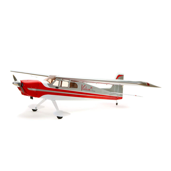
- Page 1 ™ Valiant 30cc Instruction Manual Bedienungsanleitung Manuel d’utilisation Manuale di Istruzioni...
-
Page 2: Safety Warnings And Precautions
Read and follow all instructions and safety precautions airworthy. before use. Improper use can result in fi re, serious injury and Horizon Hobby, LLC. For up-to-date product literature, visit horizonhobby. com and click on the support tab for damage to property. this product. -
Page 3: Warnungen Und Sicherheit- Svorkehrungen
Überwachung eines Erwachsenen. Verwenden Sie das Produkt nicht mit inkompatiblen Komponenten oder Gebrauch oder Entsorgung von Akkus. Falsche Behandlung verändern es in jedweder Art ausserhalb der von Horizon Hobby, LLC. vorgegebenen Anweisungen. Diese von LiPo Akkus kann zu Feuer mit Körperverletzungen und Bedienungsanleitung enthält Anweisungen für Sicherheit, Betrieb und Wartung. -
Page 4: Avertissements Relatifs À La Sécurité
L’UTILISATION La totalité des instructions, garanties et autres documents est sujette à modifi cation à la seule discrétion d’Horizon Hobby, LLC. Pour obtenir la documentation à jour, rendez-vous sur le site horizonhobby.com et cliquez • Inspectez votre modèle avant chaque vol. -
Page 5: Avvertimenti E Precauzioni Per La Sicurezza
Non usare componenti non compatibili o alterare il prodotto in nessuna maniera al di fuori delle istruzioni fornite da Horizon Hobby, LLC. Questo kit comprende delle parti di piccole dimensioni e non Questo manuale contiene le istruzioni per un funzionamento e una manutenzione sicuri. - Page 6 •SPECIFICATIONS•SPEZIFIKATIONEN •LARGE PARTS LAYOUT•BAUTEILE (OHNE KLEINTEILE) •SPÉCIFICATIONS•SPECIFICHE •GRANDES PIÈCES•SCHEMA DEI COMPONENTI GRANDI 108.3 in (275 cm) 1663.0 sq in (107.3 dm2) Total/Totale 78.2 in (199 cm) 16.5–17.5 lb (7.48–7.94 kg) 2-Stroke Gas/2-Takt Benziner/ 2 temps Essence/2-Tempi Gas 30cc Electric Power/Elektro Antrieb/ Moteur électrique (EP)/Motore elettrico Power 160 5-channel (or greater) with 8 servos...
- Page 7 •REPLACEMENT PARTS•ERSATZTEILE•PIÈCES DE RECHANGE•RICAMBI English Deutsch Français Italiano HAN506001 Fuselage Rumpf Fuselage Fusoliera HAN506002 Left Wing with Aileron and Flap Tragfl äche Links mit Querruder und Klappe Aile gauche avec aileron et volet Semiala sinistra con alettone e fl ap HAN506003 Right Wing with Aileron and Flap Tragfl...
- Page 8 •REQUIRED RADIO EQUIPMENT (NOT INCLUDED)•ERFORDERLICHE RC AUSRÜSTUNG (NICHT IM LIEFERUMFANG) •EQUIPEMENT RADIO REQUIS (NON FOURNIS)•APPARECCHIATURE RADIO (NON COMPRESO) Part # English Deutsch Français Italiano SPMAR8000 AR8000 8-Channel DSMX ® Receiver AR8000 8-Kanal DSMX Receiver Récepteur 8 voies DSMX AR8000 Ricevitore AR8000 DSMX a 8 canali SPMSA6180 (8) A6180 Digital Aircraft Servo Spektrum A6180 Digital Flug Servo...
- Page 9 •OPTIONAL ITEMS (NOT INCLUDED)•OPTIONALE TEILE (NICHT IM LIEFERUMFANG)•ELÉMENTS OPTIONNELS (NON FOURNIS)•ARTICOLI OPZIONALI (NON COMPRESO) Part # English Deutsch Français Italiano SPM9548 TM1000 DSMX Full Range Aircraft Telemetry Module Spektrum DSMX Full Range Telemetriemodul TM1000 Module de télémétrie avion TM1000 DSMX Modulo telemetria per aereo a piena portata TM1000 DSMX JRPG370A...
- Page 10 •REQUIRED TOOLS (NOT INCLUDED)•BENÖTIGTES WERKZEUG (NICHT IM LIEFERUMFANG)•OUTILS REQUIS (NON FOURNIS)•ATTREZZI NECESSARI (NON COMPRESO) English Deutsch Français Italiano Box wrench: 7/16 inch, 1/2 inch, 5/8 inch Ringschlüssel 7/16 inch, 1/2 inch, 5/8 inch Clé hexagonales 7/16, 1/2 et 5/8 Chiavi: 7/16 inch, 1/2 inch, 5/8 inch Crimping tool Crimpzange Pince à...
-
Page 11: Before Starting Assembly
•BEFORE STARTING ASSEMBLY •VOR DEM ZUSAMMENBAU •AVANT DE COMMENCER L’ASSEMBLAGE •PRIMA DI INIZIARE IL MONTAGGIO • Remove parts from bag. • Entnehmen Sie zur Überprüfung jedes Teil der Verpackung. • Retirez toutes les pièces des sachets pour les inspecter. • Togliere tutti i pezzi dalla scatola. •... - Page 12 •ASSEMBLY SYMBOL GUIDE•MONTAGE SYMBOLE•GUIDE DES SYMBOLES POUR ASSEMBLAGE•GUIDA AI SIMBOLI DI ASSEMBLAGGIO Apply threadlock Assemble right and left Use a felt-tipped pen Apply oil Schraubensicherungslack verwenden Links und rechts montieren Verwenden Sie einen Faserstift Öl verwenden Utilisez du frein fi let Assemblez à...
- Page 13 •FLAP HINGING•ANSCHLAGEN DER KLAPPEN•ARTICULATION DES VOLETS•INCERNIERARE I FLAP The aileron and flap for each wing panel are stapled together for the right and left wing panels. Die Querruder und Klappen sind für jede Tragflächenseite zusammen geheftet. L’aileron et le volet pour chaque panneau d’aile sont reliés ensemble pour les panneaux d’aile droits et gauches.
- Page 14 Place a T-pin in the center of each hinge for the ailerons. Slide the hinges into position with the T-pin resting against Fit the aileron to the wing panel and remove the T-pins from Use a piece of low-tack tape to hold the aileron in position. the edge of the control surface.
- Page 15 Adjust the position of the fl ap hinges so the fl ap aligns with Apply a small amount of oil to the fl ex point of the hinge to Use a toothpick to apply epoxy to both the exposed hinge and the aileron.
- Page 16 •HINGING THE AILERONS •MONTAGE DER QUERRUDER •POSE DES CHARNIÈRES DES AILERONS •INCERNIERARE GLI ALETTONI Check the alignment of the fl ap to the aileron and make any Once the epoxy has fully cured, apply a few drops of thin CA fi...
- Page 17 •AILERON AND FLAP SERVO INSTALLATION •EINBAU DES QUERRUDER- UND DES KLAPPENSERVOS •INSTALLATION DES SERVOS D’AILERON ET DE VOLET •INSTALLAZIONE SERVI ALETTONI E FLAP Use a piece of low-tack tape to hold the aileron in position Use a felt-tipped pen to mark the aileron servo cover near when installing the control horn.
- Page 18 Remove the aileron servo cover from the wing, and use a felt-tipped pen to mark the trailing edge inside the cover. The servo Secure the aileron servo using the hardware included with the servo and a 2mm hex wrench. With the servo centered, secure output will face toward the trailing edge when installed.
- Page 19 Secure a 24-inch (600mm) extension to the servo lead using Use a felt-tipped pen to mark the fl ap servo cover near the Remove the fl ap servo cover from the wing, and use a felt- Tie the string located inside the wing to the end of the 24- string or dental fl...
- Page 20 M2 x 12 Use a #1 Phillips screwdriver to tighten the screws that Use a square against the hinge line of the aileron and Use a hobby knife and #11 blade to remove the control Position the control horn at the mark made in the previous step. secure the aileron servo cover to the wing.
- Page 21 M2 x 12 Use a pin vise and 1/16-inch (1.5mm) drill bit to drill the Use a #1 Phillips screwdriver to thread a screw into each hole, cutting threads in the surrounding wood. Remove the screws, Cut a piece of silicone fuel tubing (not included) to a length of holes for the control horn mounting screws.
- Page 22 4-40 x 3 inch 4-40 Thread 4-40 nuts and the clevises prepared in the previous Use a 2mm hex wrench to thread the servo mounting screws Apply a few drops of thin CA into each of the servo mounting step onto the threaded rod. Start with the length shown, which into each of the servo mounting holes.
- Page 23 Center the fl ap servo using the radio system. Place the servo Attach the servo arm to the fl ap servo so the arm is Secure the fl ap servo to the mount using the screws provided Cut a piece of silicone fuel tubing (not included) to a length of arm on the servo so the arms are perpendicular to the servo perpendicular to the servo center line.
- Page 24 4-40 x 3 inch 4-40 Thread 4-40 nuts and the clevises prepared in the previous Attach the linkage to the outer hole of the servo arm, which Secure a 6-inch (150mm) extension to the servo lead using Tie the string to the extensions for both the fl ap and aileron step onto the threaded rod.
- Page 25 Insert the fl ap servo assembly into the wing with the servo Attach the linkage to the fl ap control horn. output facing the trailing edge. Guide the linkage out Schließen Sie die Anlenkung am Klappenruderhorn an. through the hole in the wing trailing edge near the fl ap control horn.
- Page 26 M2 x 12 Hold the servo from the wing, and turn on the radio system. Set the fl ap switch at the transmitter to the UP position and lower Use a #1 Phillips screwdriver to tighten the screws that the fl ap into the wing. Check that the fl ap is in the UP position. If not, adjust the linkage as necessary. secure the fl...
- Page 27 •RUDDER PREPARATION•VORBEREITUNG DES SEITENRUDERS•ASSEMBLAGE DE LA DÉRIVE•PREPARAZIONE DEL TIMONE Loosen the setscrew in the wheel collar and slide it down Use medium grit sandpaper to roughen the tail gear wire Fit the tail gear wire back to the rudder. Use low-tack tape to against the spring.
- Page 28 •ELEVATOR INSTALLATION•MONTAGE DES HÖHENRUDERS •INSTALLATION DE LA PROFONDEUR•INSTALLAZIONE DELL’ELEVATORE 2-56 x 3/4 2-56 Use a hobby knife and #11 blade to remove the control horn Fit the remaining control horn on the screws, then thread the backplates from the control horns. Fit the screws into one of nuts onto the screws.
- Page 29 Apply thin CA to both sides of each CA hinge. Work the Use a pin vise and 5/64-inch (2mm) drill bit to drill the holes Use side cutters to trim the excess screws above the control control surface through its range of motion a few times to in the elevator for the control horn mounting screws through horn backplate.
- Page 30 •FINAL EMPENNAGE INSTALLATION•ENDMONTAGE DES LEITWERKS •INSTALLATION FINALE DE L’EMPENNAGE•INSTALLAZIONE FINALE DELL’IMPENNAGGIO If you wish to use epoxy in addition to the hardware listed to attach the fin and stabilizer, skip to the following section, “Optional Glue-On Fin and Stabilizer.” Sollten Sie zusätzlich zur Schraubbefestigung das Leitwerk mit Epoxy kleben wollen, lesen Sie bitte das nächste Kapitel “Optionale Verklebung von Finne und Leitwerk.”...
- Page 31 •OPTIONAL GLUE-ON FIN AND STABILIZER•OPTIONALE VERKLEBUNG VON FINNE UND LEITWERK •COLLAGE OPTIONNEL DE LA DÉRIVE ET DU STABILISATEUR•INCOLLAGGIO OPZIONALE DI DERIVA E STABILIZZATORE We have added an additional section for those that may wish to use epoxy in addition to the hardware listed to secure the fin and stabilizer.
- Page 32 6-32 x 1 inch Hinge the rudder and fi n. Follow the procedure as outlined in the previous sections of the manual, making sure the top of the fi n and rudder are aligned before applying thin CA to Use a hobby knife and #11 blade to remove the covering Apply 15-minute epoxy to the exposed wood before attaching the fi...
- Page 33 6-32 x 1 inch Fit the empennage to the fuselage. Use a felt-tipped Use a hobby knife and #11 blade to remove the covering 1/16 inch (1.5mm) inside the lines drawn in the previous step. Apply 15-minute epoxy to the exposed wood before attaching pen to trace the outline of the fuselage onto the bottom the stabilizer to the fuselage.
- Page 34 •TAIL WHEEL BRACKET INSTALLATION•MONTAGE DES SPORNRADHALTERS •RUDDER AND ELEVATOR SERVO •FIXATION DE LA PLATINE DE LA ROULETTE DE QUEUE•INSTALLAZIONE SUPPORTO RUOTA DI CODA INSTALLATION •EINBAU VON HÖHEN UND SEITENRUDERSERVO •INSTALLATION DES SERVOS DE PROFONDEUR ET DE DÉRIVE •INSTALLAZIONE SERVI TIMONE ED ELEVATORE 4-40 x 5/8 inch Use a fl...
- Page 35 Center the elevator servo using the radio system. Fit the servo arm to the servo, aligning one arm perpendicular to the pushrod. Use side cutters to remove any arms that will Thread a servo mounting screw into each of the holes using Cut a piece of silicone fuel tubing (not included) to a length of interfere with the operation of the servo.
- Page 36 Remove the servo arm from the servo. Attach one of the Slide the silicone tubing over the clevises to secure their prepared clevises to the arm 5/8 inch (16mm) from the position. Tighten the nuts against the clevises to prevent center of the arm.
- Page 37 •RUDDER LINKAGE INSTALLATION•EINBAU DER RUDERANLENKUNG•INSTALLATION DE LA TRINGLERIE DE LA DÉRIVE•INSTALLAZIONE DEL COMANDO TIMONE When installing the cable ends, make sure the cable does not loop over and get stuck on the fitting. Bitte achten Sie bei der Montage der Kabelenden darauf, dass die Schlaufe nicht zu groß...
- Page 38 Attach the ends of the cables to the heavy-duty rudder servo Center the rudder using the radio system. Secure the rudder arm. The holes are 13/16 inch (21mm) from the center of the servo arm using the screw provided with the servo and a arm as shown.
- Page 39 •RECEIVER AND RECEIVER BATTERY INSTALLATION•EINBAU VON EMPFÄNGER UND EMPFÄNGERAKKU •INSTALLATION DU RÉCEPTEUR ET DE LA BATTERIE DU RÉCEPTEUR•INSTALLAZIONE DI RICEVITORE E BATTERIA Wrap the receiver battery in foam and use hook and loop tape (not included) to secure the battery in the fuselage. Secure the lead from the switch to the battery.
- Page 40 Optional Remote Received Location Optionale Einbauposition des Satellitenempfängers Emplacement alternatif du récepteur satellite Posizione del ricevitore remoto opzionale Connect the servos, switch harness and extensions to the Use hook and loop tape to secure the remote receiver appropriate ports of the receiver. Use hook and loop tape in the fuselage.
- Page 41 •ENGINE INSTALLATION•MOTOREINBAU•INSTALLATION DU MOTEUR•INSTALLAZIONE DEL MOTORE 10-32 x 2 inch Attach the engine to the fi rewall using the hardware listed Prepare the holes for the throttle servo by threading, then and the aluminum spacers. Use a 5/32-inch hex wrench to removing, a servo mounting screw into each hole.
- Page 42 M2 x 12 Use side cutters to trim the pushrod tube at the front edge Use the radio system to center the throttle servo. Place the arm of the servo. on the servo so it is perpendicular to the servo center line. Attach the ball end to the carburetor arm using the hardware listed.
- Page 43 Use the radio to move the throttle servo to the closed Use pliers to make a 90-degree bend in the pushrod at the Use a pin vise and 5/32-inch drill bit to enlarge the outer Connect the throttle pushrod to the servo arm using a nylon position.
- Page 44 4-40 x 1/2-inch Check that the carburetor opens and closes fully using the Inspect the fuel tank to determine which tube is for the vent radio system. Once adjusted, install the screw securing the and clunk. After marking them on the tubes, slide the tank servo arm to the servo.
- Page 45 Wrap the ignition module and ignition battery in foam (not Route the lead for the plug through the opening at the front Secure the lead for the ignition module so it can’t interfere included), then secure them in the fuselage using hook and of the fuselage.
- Page 46 •EP MOTOR INSTALLATION•ELEKTROMOTOR EINBAU •INSTALLATION DE LA MOTORISATION ÉLECTRIQUE•INSTALLAZIONE MOTORE ELETTRICO Route the fuel lines for the engine as necessary. Make sure all lines are secure so they don’t interfere with the operation 10-32 x 7/8 inch of the engine. We drilled a hole in the sub fi rewall to route the fi...
- Page 47 4-40 x 1 inch Apply hook and loop tape (not included) to the battery tray. Apply hook and loop tape (not included) to the batteries. Position the tape so it will be underneath the batteries when Kleben Sie das Klettband (nicht im Lieferumfang) they are placed on the tray.
- Page 48 •COWLING INSTALLATION•EINBAU MOTORHAUBE •INSTALLATION DU CAPOT•INSTALLAZIONE CAPOTTINA MOTORE 1/4-20 x 1 inch Place the batteries on the battery tray. Use the hook and loop straps included with the EP kit to secure the batteries to the tray. Fit the battery tray into the fuselage. The tray will key into the back of the fi...
- Page 49 Slide the cowling into position, with the card stock on Use a pin vise and 5/64-inch (2mm) drill bit to drill the Remove the cowling from the fuselage. Use a pin vise and the outside of the cowling. Fit the spinner backplate (and mounting holes in the cowling.
- Page 50 A cooling baffle template has been provided for use with the Evolution 33GX. More important than inlet and exit air opening sizes and ratios, is that the incoming air be used effectively. The baffle forces air through the cooling fins, rather than allowing air to pass around the cylinder. Für den Evolution 33GX finden Sie eine Vorlage für ein Luftleitblech in dieser Anleitung.
- Page 51 4-40 x 1/2 inch Use the screws prepared in the previous step to secure the Slide the spinner backplate and propeller on the engine While holding the larger nut with the 5/8-inch box wrench, cowling to the fuselage. Use a 5/64-inch hex wrench to shaft.
- Page 52 •LANDING GEAR INSTALLATION•MONTAGE DES FAHRWERKS •INSTALLATION DU TRAIN D’ATTERRISSAGE•INSTALLAZIONE DEL CARRELLO Use a rotary tool and cut-off wheel to trim the bolt for the spinner when using the recommended gas engine. M3 x 3 Verwenden Sie einen elektrischen Drehschleifer mit Trennscheibe um den Spinnerbolzen für den empfohlenen Benzinmotor herzustellen.
- Page 53 •OPTIONAL TUNDRA LANDING GEAR INSTALLATION •MONTAGE DES OPTIONALEN TUNDRA FAHRWERK. •INSTALLATION DU TRAIN AMORTI OPTIONNEL •INSTALLAZIONE DEL CARRELLO OPZIONALE TUNDRA 4-40 x 1/2 inch Fit the wheel pants over the wheel and axle. Use the hardware listed to attach the wheel pants to the landing gear.
- Page 54 The landing gear will need to be assembled •OPTIONAL FLOAT INSTALLATION•OPTIONALE MONTAGE DER SCHWIMMER before they can be attached to the fuselage. •INSTALLATION DES FLOTTEURS OPTIONNELS•INSTALLAZIONE DEI GALLEGGIANTI OPZIONALI Follow the instructions in the Hangar 9 ® 1/4- Scale PA-18 Super Cub ARF (HAN4540). Bevor Sie das Fahrwerk am Rumpf montieren muß...
- Page 55 Use a hobby knife and #11 blade to remove the covering and expose the pre-installed blind nuts located 10 inches (273mm) back from the forward holes for the included landing gear. Entfernen Sie mit einem Hobbymesser und 11 Klinge die Bespannung über den bereits eingebauten Blindmuttern die sich 273mm hinter den vorderen Löchern für das im Lieferumfang befi...
- Page 56 •WINDOW INSTALLATION•MONTAGE DER FENSTER•INSTALLATION DES VITRAGES•INSTALLAZIONE DELLE FINESTRE Connect the extension from the fl oat servo to the extension at the fuselage. Schließen Sie die Verlängerung vom Schwimmerservo an die Verlängerung im Rumpf an. Use hobby scissors and a hobby knife with a #11 blade to Use canopy glue to glue the windows from the inside of the Use canopy glue to glue the front windscreen to the fuselage.
- Page 57 •WING INSTALLATION•MONTAGE DER TRAGFLÄCHEN•INSTALLATION DE L’AILE•MONTAGGIO DELL’ALA Slide the wing tube into the wing tube socket. Slide the wing panel tightly against the fuselage. Schieben Sie den Flächenverbinder in die Öffnung an der Schieben Sie die Fläche fest an den Rumpf. Slide the wing panel into position.
- Page 58 •AERO TOW PREPARATION•VORBEREITUNG FÜR DAS SCHLEPPFLIEGEN •PRÉPARATION AU REMORQUAGE•PREPARAZIONE PER IL TRAINO AEREO Your Valiant 30cc can be used in aero towing. The best tow hook location is on the top of the fuselage at the wing trailing edge, immediately behind the hatch. Die Vaillant 30cc kann auch für das Schleppen von Segelfl...
-
Page 59: Center Of Gravity
•CENTER OF GRAVITY •DER SCHWERPUNKT An important part of preparing the aircraft for fl ight is properly balancing the model. Ein sehr wichtiger Teil in der Flugvorbereitung ist es das Flugzeug richtig auszubalancieren. 1. Attach the wing panels to the fuselage. Make sure to connect the leads from the aileron to the appropriate leads from the 1. -
Page 60: Centre De Gravité
•CENTRE DE GRAVITÉ •CENTRO DI GRAVITA’ (BARICENTRO) Une des étapes importantes de la préparation d’un modèle est son équilibrage. Un punto importante per preparare l’aereo al volo è quello di fare un centraggio corretto. 1. Fixez les ailes au fuselage. Vérifi ez que les ailerons sont reliés aux prises appropriées du récepteur. Contrôlez que les câbles 1. -
Page 61: Control Throws
•CONTROL THROWS •RUDERAUSSCHLÄGE 1. Turn on the transmitter and receiver of your model. Check the movement of the rudder using the transmitter. When the stick 1. Schalten Sie den Sender und Empfänger ihres Modells ein. Prüfen Sie die Seitenruderaussschläge mit dem Sender. is moved to the right, the rudder should also move right. -
Page 62: Débattements
•DÉBATTEMENTS •CORSE DEI COMANDI 1. Mettez l’émetteur et le récepteur sous tension. Contrôlez les mouvements de la dérive en utilisant votre émetteur. Quand le 1. Accendere trasmettitore e ricevitore del modello. Controllare i movimenti del timone agendo sul trasmettitore. Quando lo manche est vers la droite, la dérive doit s’orienter vers la droite. -
Page 63: Preflight Checklist
•PREFLIGHT CHECKLIST •VORFLUGKONTROLLE •CHECKLIST D’AVANT VOL •LISTA DEI CONTROLLI PRIMA DEL VOLO • Charge the transmitter, receiver and motor battery for • Laden Sie den Sender- ,Empfänger- und Zündakku für • Chargez la batterie de votre émetteur, de réception • Caricare le batterie di trasmettitore, ricevitore e your airplane. -
Page 64: Daily Flight Checks
•DAILY FLIGHT CHECKS •TÄGLICHER FLUG CHECK •CONTRÔLES SYSTÉMATIQUES •CONTROLLI DI VOLO GIORNALIERI • Check the battery voltage of the transmitter battery. Do • Überprüfen Sie die Spannung des Senderakkus. Fliegen • Contrôlez la tension de la batterie de l’émetteur. Ne volez •... - Page 65 An Online Service Request is available at accepts money orders and cashier’s checks, as well as Visa, service by anyone other than a Horizon Hobby authorized of use, setup or assembly, the user accepts all resulting http://www.horizonhobby.com/content/_service-center_ MasterCard, American Express, and Discover cards.
-
Page 66: Garantie Und Service Informationen
Reparaturversuche, die nicht von Horizon ausgeführt wurden aus. Rücksendungen durch den Käufer direkt an Horizon oder Anleitung enthält Sicherheitshinweise und Vorschriften Exklusive Garantie ¬ Horizon Hobby LLC (Horizon) Liegt eine kostenpfl ichtige Reparatur vor, erstellen wir einen eine seiner Landesvertretung bedürfen der Schriftform. -
Page 67: Garantie Et Réparations
Questions, assistance et réparations Réparations payantes ou d’une manipulation erronés, d’accidents ou encore du Garantie exclusive - Horizon Hobby, LLC. (Horizon) garantit fonctionnement ainsi que des tentatives d’entretien ou de Votre revendeur spécialisé local et le point de vente ne En cas de réparation payante, nous établissons un devis... - Page 68 Horizon non si riterrà responsabile per danni speciali, Se il prodotto deve essere ispezionato o riparato, si prega di La garanzia esclusiva - Horizon Hobby, LLC., (Horizon) diretti, indiretti o consequenziali; perdita di profi tto o di rivolgersi ad un rivenditore specializzato o direttamente ad garantisce che i prodotti acquistati (il “Prodotto”) sono...
-
Page 69: Instructions For Disposal Of Weee By Users In The European Union
Horizon Hobby Limited +44 (0) 1279 641 097 Harlow, Essex, CM18 7NS, United Kingdom Horizon Technischer Service service@horizonhobby.de Christian-Junge-Straße 1 Germany Sales: Horizon Hobby GmbH +49 (0) 4121 2655 100 25337 Elmshorn, Germany infofrance@horizonhobby.com Service/Parts/Sales: 11 Rue Georges Charpak France... -
Page 70: Academy Of Model Aeronautics National Model Aircraft Safety Code
•ACADEMY OF MODEL AERONAUTICS NATIONAL MODEL AIRCRAFT SAFETY CODE Effective January 1, 2014 EXCEPTIONS: 3. At all fl ying sites a safety line(s) must be established in C. FREE FLIGHT front of which all fl ying takes place. (AMA Document #706.) A. - Page 71 •FWD Face•Vorne •Face Avant•Lato Anteriore •RH •LH •Rechts •Links •Droite (Côté droit) •Gauche (Côté gauche) •DX •SX...
- Page 72 © 2014 Horizon Hobby, LLC. Hangar 9, DSMX, Evolution, Valiant, EC5 and the Horizon Hobby logo are trademarks or registered trademarks of Horizon Hobby, LLC. The Spektrum trademark is used with permission of Bachmann Industries, Inc. All other trademarks, service marks and logos are the property of their respective owners.