ASO Safety Solutions ISK 74 Manuel D'utilisation
Table des Matières
Les langues disponibles
Les langues disponibles
Liens rapides
ISK 74
Betriebsanleitung (Original)
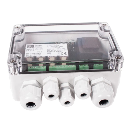
ISK 74 Induktives Sicherheitsschaltgerät
Operating Manual
ISK 74 Inductive Safet�� Rela��
74 Inductive Safet�� Rela��
Inductive Safet�� Rela��
Manuel d'utilisation
ISK 74 Relais de sécurité inductif
Manuale di istruzione
ISK 74 Sistema di sicurezza induttivo
Gebruiksaanwijzing
ISK 74 Inductief veiligheidsrelais
Rela��
Seite 3-11
Page 13-21
Page 23-31
Pagina 33-41
Pagina 43-51
Chapitres
Table des Matières

Manuels Connexes pour ASO Safety Solutions ISK 74


Sommaire des Matières pour ASO Safety Solutions ISK 74
- Page 1 Page 13-21 ISK 74 Inductive Safet�� Rela�� 74 Inductive Safet�� Rela�� Inductive Safet�� Rela�� Rela�� Manuel d’utilisation ISK 74 Relais de sécurité inductif Page 23-31 Manuale di istruzione Pagina 33-41 ISK 74 Sistema di sicurezza induttivo Gebruiksaanwijzing ISK 74 Inductief veiligheidsrelais...
- Page 2 Übergabedokumentation / Documentation / Documentation de datation / Documentazione di consegna / Documentatie Anlagenbeschreibung / Description / Description du système / Descrizione impianto / Beschrijving van de installatie Anlagenart / T��pe of plant / Sorte du s��stème / Tipo d’impianto / T��pe installatie Hersteller / Manufacturer / Fabricant / Produttore / Fabrikant Seriennummer / Serial number / Numéro de série / Numero di serie / Seriennummer Datum der Inbetriebnahme / Commissioning date / Date de mise en marche / Data della messa in...
- Page 23 ISK 74 Relais de sécurité inductif Table des matières Table des matières ....23 Prescriptions générales de sécurité et mesures de protection ....24 Généralités .
-
Page 24: Isk 74 Relais De Sécurité Inductif
ISK 74 Relais de sécurité inductif 2. Prescriptions générales de sécurité et mesures de protection • Le fabricant et l'utilisateur du s��stème / de la machine sur lequel est placé le dispositif deprotec- tion, ont la responsabilité d'appliquer et de suivre toutes les directives et règles de sécurité en vigueur. -
Page 25: Généralités
Les états de commutation des relais et la tension de service sont indiqués par des LED. 5. Utilisation conforme Le s��stème de transmission de sécurité ISK 74 est conçu pour l'évaluation de barres palpeuses stationnaires et mobiles avec une résistance constante de 8,2 kW. -
Page 26: Composants Du S
ISK 74 Relais de sécurité inductif 6. Composants du système sur le portail stationary opening closing 1 2 Exemple d'application 1 Appareil de commande ISK 74 2 Noyau de bobine fixe La disposition des différents composants 3 No��au de bobine mobile dépend de la construction spécifique du portail... -
Page 27: Modèles Et Fixation Mécanique
8. Raccordement de l'appareil 8.1 Conditions • L'alimentation de l'ISK 74 doit répondre aux exigences de la très basse tension de protection (TBTP). • Les câbles posés en extérieur ou en dehors de l'armoire électrique doivent être protégés de façon appropriée. -
Page 28: Raccordement Des Émetteurs De Signaux Mobiles
ISK 74 Relais de sécurité inductif 9. Raccordement des émetteurs de signaux 9.1 Raccordement au noyau de bobine (figure 1) Les barres palpeuses mobiles (SKL) sont reliées au no��au de bobine mobile. Pour cela, le mouvement de FERMETURE de la barre palpeuse mobile est raccordé... -
Page 29: Diagnostic D'erreurs
Si l'erreur n'est pas dans le câblage, il est possible de vérifier le fonctionnement de l'électronique en pontant toutes les entrées de barre palpeuse sur le s��stème électronique d'évaluation ISK 74-31 (bornes Stationary Opening et Closing) et sur le no��au de bobine mobile (raccords O et C) avec une résistance de 8,2 kW chacune. -
Page 30: Mise Hors-Service Et Élimination
ISK 74 Relais de sécurité inductif 12. Mise hors-service et élimination Les produits fabriqués par ASO sont prévus exclusivement pour l'emploi industriel (B2B). Après la fin d'utilisation, les produits doivent être éliminés en respectant toutes les consignes locales, régionales et nationales en vigueur. -
Page 31: Déclaration De Conformité Ce
14. Déclaration de conformité CE Nous déclarons par la présente que les produits suivants des séries : ISK 74-30 (article n° 204653, format de numéro de série ����mmnnnnn) ISK 74-31 (article n° 204650, format de numéro de série ����mmnnnnn) ISK 74-33 (article n°... - Page 52 12.DB.06.001 Technische Daten Rev 04 Deutsch Technische Änderungen vorbehalten. Für Irrtümer und Druckfehler kann keine Haftung übernommen werden. 12.DB.06.001 Technical Specifications Rev 04 English Subject to technical modifications. No liabilit�� can be assumed for errors or misprints. 12.DB.06.001 Données techniques Rév 04 Français Sous réserve de modifications techniques.