Table des Matières
Publicité
Les langues disponibles
Les langues disponibles
Liens rapides
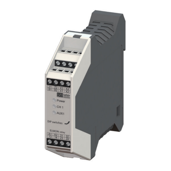
Sicherheitsschaltgerät / Safety Relay / Relais de sécurité / Relè di sicurezza / Veiligheidsrelais
ELMON relay 41-322 / 41-822
Betriebsanleitung
ELMON relay 41-322 / 41-822 Sicherheitsschaltgerät
Operati ng Manual
ELMON relay 41-322 / 41-822 Safety Relay
Manuel d´uti lisati on
ELMON relay 41-322 / 41-822 Relais de sécurité
(Original, Gülti gkeit siehe letzte Seite)
(see last page for validity)
(Validité voir la dernière page)
Seite 3-13
Page 14-24
Page 25-35
Publicité
Chapitres
Table des Matières

Manuels Connexes pour ASO Safety Solutions ELMON 41-322


Sommaire des Matières pour ASO Safety Solutions ELMON 41-322
- Page 1 Sicherheitsschaltgerät / Safety Relay / Relais de sécurité / Relè di sicurezza / Veiligheidsrelais ELMON relay 41-322 / 41-822 Betriebsanleitung (Original, Gülti gkeit siehe letzte Seite) ELMON relay 41-322 / 41-822 Sicherheitsschaltgerät Seite 3-13 Operati ng Manual (see last page for validity) ELMON relay 41-322 / 41-822 Safety Relay Page 14-24 Manuel d´uti lisati on (Validité voir la dernière page)
- Page 2 Übergabedokumentation / Documentation / Documentation de datation / Documentazione di consegna / Documentatie Anlagenbeschreibung / Description / Description du système / Descrizione impianto / Beschrijving van de installatie Anlagenart / Type of plant / Sorte du système / Tipo d’impianto / Type installatie Hersteller / Manufacturer / Fabricant / Produttore / Fabrikant Seriennummer / Serial number / Numéro de série / Numero di serie / Seriennummer Datum der Inbetriebnahme / Commissioning date / Date de mise en marche / Data della messa in funzione...
-
Page 3: Table Des Matières
ELMON relay 41-322 / 41-822 Sicherheitsschaltgerät 1. Inhaltsverzeichnis 1. Inhaltsverzeichnis ......3 2. Allgemeine Sicherheitsbestimmungen und S chutzmaßnahmen . 4 3. Allgemeines und Funktionsbeschreibung . -
Page 4: Allgemeine Sicherheitsbestimmungen Und Schutzmaßnahmen
Sicherheitsschaltgerät 2. Allgemeine Sicherheitsbestimmungen und Schutzmaßnahmen • Hersteller und Benutzer der Anlage / Maschine, an der die Schutzeinrichtung verwendet wird, sind dafür verantwortlich, alle geltenden Sicherheitsvorschriften und -regeln in eigener Verantwortung abzustimmen und einzuhalten. • Die Schutzeinrichtung garantiert in Verbindung mit der übergeordneten Steuerung eine funktionale Sicherheit, nicht aber die Sicherheit der gesamten Anlage / Maschine. Vor dem Einsatz des Gerätes ist deshalb eine Sicherheitsbetrachtung der gesamten Anlage / Maschine nach der Maschinenrichtlinie 2006/42/EG oder nach entsprechender Produktnorm notwendig. -
Page 5: Allgemeines Und Funktionsbeschreibung
ELMON relay 41-322 / 41-822 Sicherheitsschaltgerät 3. Allgemeines und Funktionsbeschreibung Das Schaltgerät ELMON relay 41-322 (41-822) dient zur Auswertung von Signalgebern wie Sicher- heitskontaktmatten, Sicherheitskontaktleisten und Sicherheitsbumpern zur Absicherung von Quetsch- und Scherstellen. An das Schaltgerät kann ein ASO Signalgeber angeschlossen werden. Die Ruhestromüberwachung des Signalgebers wird durch einen integrierten Abschlusswiderstand im Signalgeber ermöglicht. Desweiteren kann das Gerät auch einen Signalgeber in Vierleitertechnik auswerten. Fließt der Soll-Ruhestrom, so sind die Sicherheitsrelais angesteuert und die Schaltkontakte geschlossen. Wird der Signalgeber betätigt oder der Signalgeberstromkreis unterbrochen, öffnen die Relais-Schaltkon- takte. -
Page 6: Bestimmungsgemäße Verwendung
Sicherheitsschaltgerät 4. Bestimmungsgemäße Verwendung Das Schaltgerät kann seine sicherheitsrelevante Aufgabe nur erfüllen, wenn es bestimmungsgemäß eingesetzt wird. Die bestimmungsgemäße Verwendung des Schaltgerätes ist der Einsatz als Schutzeinrichtung in Verbindung mit Sicherheitskontaktmatten, Sicherheitsbumpern und Sicherheitskontaktleisten mit 8,2 kΩ Widerstand zur Ruhestromüberwachung. Eine Verwendung des Schaltgerätes in Höhen über 2000 m über NHN oder in explosionsgefährdeten Bereichen ist nicht zugelassen. Ein anderer oder darüber hinausgehender Einsatz ist nicht bestimmungsgemäß. Für Schäden, die aus nicht bestimmungsgemäßen Verwendungen entstehen, übernimmt der Hersteller keine Haftung. Der Einsatz bei Sonderanwendungen bedarf einer Freigabe vom Hersteller. 5. Anwendungsbeispiele 8,2 ΚΩ +24 V L1 L2 L3 Reset Sicherheitsgerichtete Überwachung von einer Sicherheitskontaktleiste mit Startfreigabe über Freigabetaster und getrennter Weiterführung der Steuerstromkreise (Kategorie 3 konforme Anwendung nach EN ISO 13849-1) Zur Funktionskontrolle der Lastschütze K1 und K2 werden die Öffnerkontakte dieser Schütze in den Start-Kreis (Z1 Z2) eingebunden. Der Melderelais-Ausgang dient zur Visualisierung des Schaltzustandes der Sicherheitskontaktleiste. Schaltbild im spannungslosen Zustand. Sensor nicht betätigt. 1 Signalgeber (Leiste, Matte oder Bumper) 2 Freigabetaster... -
Page 7: Geräteübersicht
ELMON relay 41-322 / 41-822 Sicherheitsschaltgerät 6. Geräteübersicht 6.1 Ausführungen Ausführung Versorgungsspannung ELMON relay 41-322 230V 50/60 Hz und 24 V AC/DC ELMON relay 41-822 120V 50/60 Hz und 24V AC/DC 6.2 Signalanzeigen LED Power (grün) Betriebszustand (an) Fehlermeldung (Pulsausgabe) LED CH 1 (rot) Signalgeber betäti gt (an) Signalgeberstromkreis unterbrochen (blinkt schnell) Fehlerselbsthaltung (blinkt langsam) -
Page 8: Dip-Schalter Zum Einstellen Der Betriebsart
Sicherheitsschaltgerät 6.4 DIP-Schalter zum Einstellen der Betriebsart „ON“: Automatischer Reset „OFF“: Fehlerselbsthaltung – manueller Reset (Werkseinstellung) „ON“: Modus Meldeausgang AUX1: RLU „OFF“: Modus Meldeausgang AUX1: RL (Werkseinstellung) 7. Betriebsarten Das Ändern sämtlicher Betriebsarten darf nur im spannungslosen Zustand durch- geführt werden! Andernfalls wechselt das Schaltgerät in den sicheren Zustand und signalisiert die fehlerhafte Konfiguration mit Fehlercode 7. 7.1 Sicherheitsausgang Getrennte oder in Reihe geschaltete Ausgabe der Steuerstromkreise (redundante Weiterführung der Schaltkontakte). Um die beiden Sicherheitsrelais getrennt zu nutzen, muss die Brücke zwischen 14 und 23 entfernt werden. -
Page 9: Mechanische Befestigung
ELMON relay 41-322 / 41-822 Sicherheitsschaltgerät 8. Mechanische Befestigung Das Schaltgerät muss fachgerecht befestigt werden: • In einem staub- und feuchtigkeitsgeschütztem Schaltschrank oder Gehäuse. • Für den Einsatz in einer Umgebung mit Verschmutzungsgrad 2. • Mit einer Schutzart von mindestens IP54. • Auf einer 35 mm DIN-Tragschiene nach EN 50 022. Die Einbaulage des Schaltgerätes ist beliebig. Das Gerät darf nicht in Bereichen mit starken Temperaturwechseln betrieben werden. -
Page 10: Anschluss Steuerstromkreise
Sicherheitsschaltgerät Sicherheitskontaktleiste SENTIR edge: Es können maximal 5 SENTIR edge in Serie geschaltet werden. Die maximale Gesamtlänge der SENTIR edge darf 100 m nicht überschreiten. Die Länge einer SENTIR edge kann bis zu 25 m betragen. Die Gesamtleitungslänge der in Serie geschalteten SENTIR edge darf 25 m nicht überschreiten. Sicherheitskontaktpuffer SENTIR bumper: Es können maximal 5 SENTIR bumper in Serie geschaltet werden. Die maximale Gesamtlänge der SENTIR bumper darf 15 m nicht überschreiten. Die Länge eines SENTIR bumper kann bis zu 3 m betragen. Die Gesamtleitungslänge der in Serie geschalteten SENTIR bumper darf 25 m nicht überschreiten. Sicherheitskontaktmatte SENTIR mat: Es können maximal 10 SENTIR mat in Serie geschaltet werden. Die maximale Gesamtfläche darf 10 m nicht... -
Page 11: Inbetriebnahme Und Funktionsprüfung
ELMON relay 41-322 / 41-822 Sicherheitsschaltgerät 10. Inbetriebnahme und Funktionsprüfung Nach entsprechendem Anschluss aller elektrischen Verbindungen und Einschalten der Versorgungsspannung muss die Anlage / Maschine auf korrekte Funktion geprüft werden. Nach erfolgreicher Inbetriebnahme ist der Sicherheits-Ausgang 13 24 angesteuert (Relaiskontakt „geschlos- sen“). Eine Betätigung des Signalgebers bewirkt ein Öffnen des Relaiskontaktes 13 24. Das Melderelais (Anschluss 31 32) schaltet entsprechend der vorliegenden DIP Schalter Stellung. Dies wird mit Hilfe der gelben LED AUX1 angezeigt. Das Sicherheitssystem muss in geeigneten Zeitabständen von Sachkundigen geprüft werden. Die Prüfung muss in jederzeit nachvollziehbarer Weise dokumentiert werden. Die Anforderungen des Anlagen- / Maschi- nenherstellers sind zu berücksichtigen und einzuhalten. -
Page 12: Technische Daten
Sicherheitsschaltgerät 13. Technische Daten Versorgungsspannung Anschlusswiderstand Signalgeber ELMON relay 41-322: 230 V AC ± 10% 50/60 Hz Nominalwert = 8,2 kΩ Netzspannung Netz ELMON relay 41-822: 120 V AC ± 10% 50/60 Hz oberer Schaltwert > 12,0 kΩ Kleinspannung 24 V AC/DC ±10% unterer Schaltwert < 5,0 kΩ Leistungsauf- 3,5 VA 230 V AC Netz_ nahme 3,8 VA 120V AC 50Hz / 3,5VA 120V AC 60Hz 1,5 W 24 V DC E_max 1,2 VA 24 V AC E_max... - Page 13 ELMON relay 41-322 / 41-822 Sicherheitsschaltgerät ELMON relay 41-312 ELMON relay 41-312 ELMON relay 41-312 ELMON relay 41-812 ELMON relay 41-812 ELMON relay 41-812 ELMON relay 41-322 ELMON relay 41-322 ELMON relay 41-322 ELMON relay 41-822 ELMON relay 41-822 ELMON relay 41-822...
- Page 14 Safety Relay 1. Table of Contents 1. Table of Contents ......14 2. General safety regulations and protection measures ..15 3. General and function description .
-
Page 15: General Safety Regulations And Protection Measures
ELMON relay 41-322 / 41-822 Safety Relay 2. General safety regulations and protection measures • The manufacturer and user of the system/machine on which the protection system is used are responsible for coordinating and adhering to all applicable safety rules and regulations under their own responsibility. • The protection system guarantees functional safety in combination with the superordinate control system, but not the safety of the entire system/machine. Thus, a safety review of the entire system/ machine in accordance with machine directive 2006/42/EC or relevant product standards is necessary prior to use of the device. -
Page 16: General And Function Description
Safety Relay 3. General and function description The ELMON relay 41-322 (41-822) switching device is used to evaluate sensors such as safety contact mats, safety contact edges and safety bumpers for securing crush and shear locations. An ASO sensor can be connected to the switching device. The steady-state current monitoring of the sensor is made possible by an integrated terminating resistor in the sensor. Furthermore, the device can also evaluate a sensor in four-wire technology. If the desired steady-state current flows, the safety relays are driven and the switching contacts closed. If the sensor is operated or the sensor circuit is interrupted, the relay switching contacts open. A signal output with potential-free switching contacts is available. An operation of the sensor causes a reaction of the signal output in accordance with the DIP switch configuration. The signal output must not execute any safety-orientated functions. It is not fail-safe and not checked by testing either. -
Page 17: Intended Use
ELMON relay 41-322 / 41-822 Safety Relay 4. Intended use The switching device can only fulfill its safety-relevant task, if it is used as intended within specifications. The intended use of the switching device is the use as a protection system in connection with safety contact mats, safety bumpers and safety contact edges with 8.2 kΩ resistance for steady-state current monitoring. It is not allowed to use the safety relay in heights over 2000 m above sea level or potentially explosive atmospheres. A different use or any use going beyond the intended use is not within specifications. The manufacturer does not accept any liability for any damage arising from use not within specifications. Any use for special applications requires prior release by the manufacturer. 5. Application example 8,2 ΚΩ +24 V L1 L2 L3 Reset Safety-orientated monitoring of a safety contact strip with start release via release pushbutton and separate... -
Page 18: Device Overview
Safety Relay 6. Device overview 6.1 Versions Version Supply voltage ELMON relay 41-322 230 V 50/60Hz and 24 V AC/DC ELMON relay 41-822 120 V 50/60 Hz and 24V AC/DC 6.2 Signal indicators LED Power (green) Operati ng state (on) Fault alarm (pulse) LED CH 1 (red) Sensor operated (on) Sensor power circuit interrupted (fast fl ashing) Fault self-retaining (slow fl ashing) -
Page 19: Dip Switch For Configuring The Operating Mode
ELMON relay 41-322 / 41-822 Safety Relay 6.4 DIP switch for confi guring the operati ng mode „ON“: Automati c reset „OFF“: Fault self-retaining – manual reset (factory se� ng) „ON“: AUX1 Mode signal output: RLU „OFF“: AUX1 Mode signal output: RL (factory se� ng) 7. Operati ng modes Changing all operati ng modes may only be carried out in voltage-free state! Other- wise, the switching device changes to the safe state and signals the faulty confi gura- ti on with error code 7. -
Page 20: Mechanical Mounting
Safety Relay 8. Mechanical mounting The switching unit must be mounted correctly: • In a dust-protected and moisture-protected switch cabinet or casing. • For use in an environment with level 2 contamination. • With a protection type of at least IP54. • On a 35 mm DIN support rail according to EN 50 022. The switching unit can be installed in any position. The unit must not be operated in areas with major temperature changes. 9. Electrical connection The switching unit can be destroyed by connection to the incorrect terminals. Lines that are routed in the open air or outside the switch cabinet must be protected accordingly. The limit values stated in the “Technical Data” for the supply voltage and the switching capability of the relay must be observed. 9.1 Supply voltage The supply voltage can optionally be effected by means of a mains voltage of 230 V AC 50/60Hz (ELMON relay 41-822: 120 V AC 50/60 Hz) or a low voltage of 24 V AC/DC. For a supply with 24 V AC/DC the voltage must correspond to the requirements for protective low voltages (SELV). The supply line to the switching device must be protected by means of a 5x20 glass tube fuse 200mA... -
Page 21: Connection Of Control Circuits
ELMON relay 41-322 / 41-822 Safety Relay Safety contact edge SENTIR edge: A maximum of 5 SENTIR edge devices can be connected in series. The maximum total length of the SENTIR edge must not exceed 100 m. The length of a SENTIR edge can be up to 25 m. The total line length of the series-connected SENTIR edge must not exceed 25 m. Safety contact bumper SENTIR bumper: A maximum of 5 SENTIR bumper devices can be connected in series. The maximum total length of the SENTIR bumpers must not exceed 15 m. The length of a SENTIR bumper may be up to 3 m. The total line length of the series-connected SENTIR bumpers must not exceed 25 m. -
Page 22: Commissioning And Function Testing
Safety Relay 10. Commissioning and function testing Following a corresponding connection of all electrical connections and switching on the supply voltage, the system / machine must be checked for correct functionality. After successful commissioning the 13 and 24 safety output is driven (relay contact “closed“). An operation of the sensor causes an opening of the 13 and 24 relay contact. The signaling relay (31 32 connection) switches in accordance with the present DIP switch position. This is indicated by means of the yellow AUX1 LED. The safety system must be inspected by competent specialists at suitable intervals. The check must be documented in a way that allows it to be traced at any time. The requirements of the system / machine manufacturer are to be taken into account and observed. -
Page 23: Technical Data
ELMON relay 41-322 / 41-822 Safety Relay 13. Technical data Supply voltage Terminati ng resistor – sensor ELMON relay 41-322: 230 V AC ± 10% 50/60 Hz Nominal value = 8,2 kΩ Mains voltage Netz ELMON relay 41-822: 120 V AC ± 10% 50/60 Hz upper switching value > 12,0 kΩ Low voltage 24 V AC/DC ±10% lower switching value < 5,0 kΩ Power 3,5 VA 230 V AC Netz_ consumpti on 3,8 VA 120V AC 50Hz / 3,5VA 120V AC 60Hz 1,5 W 24 V DC E_max... - Page 24 Safety Relay ELMON relay 41-312 ELMON relay 41-312 ELMON relay 41-312 ELMON relay 41-812 ELMON relay 41-812 ELMON relay 41-812 ELMON relay 41-322 ELMON relay 41-322 ELMON relay 41-322 ELMON relay 41-822 ELMON relay 41-822 ELMON relay 41-822...
- Page 25 ELMON relay 41-322 / 41-822 Relais de sécurité 1. Table des matières 1. Table des matières......25 2. Normes de sécurité générales et mesures de protection .
-
Page 26: Normes De Sécurité Générales Et Mesures De Protection
Relais de sécurité 2. Normes de sécurité générales et mesures de protection • Le fabricant et l‘utilisateur du site/de la machine où l‘on utilise le dispositif de sécurité sont responsables de déterminer et respecter toutes les normes et règles de sécurité selon leur propre responsabilité. • Le dispositif de protection garantit, en connexion avec la commande ci-dessus, une sécurité fonctionnelle mais pas la sécurité de l‘ensemble du site/de la machine. Avant d‘utiliser l‘appareil, il est nécessaire d‘évaluer la sécurité de l‘ensemble du site/de la machine selon la directive de la machine 2006/42/EG ou selon la norme de produit correspondante. -
Page 27: Relais De Sécurité
ELMON relay 41-322 / 41-822 Relais de sécurité 3. Généralités et description de fonction L‘appareil de commutation ELMON relay 41-322 (41-822) sert au traitement de générateurs de signal comme des tapis de contact de sécurité, des profils de contact de sécurité et des bumpers de sécurité pour points de cisaillement et de croisement. Sur l‘appareil de commutation, on peut fixer un générateur de signal ASO. La surveillance du courant de repos du générateur de signal est rendue possible grâce à une résistance de terminaison intégrée dans le générateur de signal. -
Page 28: Utilisation Conforme
Relais de sécurité 4. Utilisation conforme L‘appareil de commutation ne peut accomplir sa tâche de sécurité que s‘il est utilisé de façon conforme. L‘utilisation conforme de l‘appareil de commutation c‘est l‘utilisation comme dispositif de protection en rapport avec les tapis de sécurité, les bumpers de sécurité et les profils des contacts de sécurité avec une résistance de 8,2 kΩ pour la surveillance du courant de repos. Une utilisation du relais de sécurité à une altitude de plus de 2000 m ou dans un domaine à danger d’explosion n’est pas autorisé. Une autre utilisation n‘est pas conforme. Le fabricant n‘est pas responsable des dommages qui proviennent d‘utilisations non conformes. L‘utilisation de façon particulière nécessite un accord du fabricant. 5. Exemple d‘utilisation 8,2 ΚΩ +24 V L1 L2 L3 Reset Une surveillance de la sécurité du profil de sécurité avec déclenchement de démarrage via un bouton de démarrage et poursuite séparée du circuit de commande (catégorie 3 utilisation conforme selon la norme EN ISO 13849-1). -
Page 29: Aperçu De L'appareil
ELMON relay 41-322 / 41-822 Relais de sécurité 6. Aperçu de l‘appareil 6.1 Modèles Modèle Tension d‘alimentati on ELMON relay 41-322 230 V 50/60Hz et 24 V AC/DC ELMON relay 41-822 120 V 50/60 Hz et 24V AC/DC 6.2 Signaux LED Power (vert) Etat de marche (allumé) Message d‘erreur (donnée impulsion) -
Page 30: Commutateur Dip Pour Réglage Mode De Fonctionnement
Relais de sécurité 6.4 Commutateur DIP pour réglage mode de fonctionnement „ON“: réinitialisation automatique „OFF“: enclenchement erreur - réinitialisation manuelle (réglage d‘usine) „ON“: mode sortie de signalisation AUX1: RLU „OFF“: mode sortie de signalisation AUX1: RL (réglage d‘usine) 7. Modes de fonctionnement Le changement de tous les modes d’utilisations doit être effectué hors-tension! Dans le cas contraire, le relais de sécurité se positionne en état sûr et signalise l’erreur pas „erreur code 7“. 7.1 Sortie de sécurité Emission séparée ou en série des circuits de courant (poursuite redondante des contacts de commutation). Pour utiliser les deux relais de sécurité séparément le pont entre 14 et 23 doit être supprimé. 7.2 Réinitialisation automatique (S1 = „ON“) Après avoir résolu une panne d‘un circuit de générateur de signal ou après une panne de courant, l‘appareil de commutation libère automatiquement la sortie. -
Page 31: Fixation Mécanique
ELMON relay 41-322 / 41-822 Relais de sécurité 8. Fixation mécanique L‘appareil de commutation doit être fixé par des professionnels: • dans une armoire électrique ou un étui à l‘abri de la poussière et de l‘humidité. • pour utilisation dans un environnement avec salissure de niveau 2. • avec un degré de protection d‘au moins IP54. • sur une barre de support de 35 mm DIN selon EN 50 022. La situation d‘installation de l‘appareil est laissée au choix de chacun. L‘appareil ne peut pas être utilisé dans des zones subissant de grandes modifications de température. 9. Connexion électrique La connexion à de mauvaises bornes peut détruire l‘appareil de commutation. Les conduits qui doivent être à l‘air libre ou à l‘extérieur de l‘armoire électrique doivent être protégés en conséquence. -
Page 32: Connexion Circuit De Câblage Électrique
Relais de sécurité Barre palpeuse SENTIR edge: Il est possible de monter au plus 5 SENTIR edge en série. La longueur totale des SENTIR edge ne doit pas dépasser 100 m. La longueur max. d‘un SENTIR edge peut être de 25 m. La longueur maximale des câbles des SENTIR edge monter en série ne doit pas dépasser 25 m. Bumper de sécurité SENTIR bumper: Il est possible de monter au plus 5 SENTIR bumper en série. La longueur totale des SENTIR bumper ne doit pas dépasser 15 m. -
Page 33: Mise En Service Et Essai De Fonction
ELMON relay 41-322 / 41-822 Relais de sécurité 10. Mise en service et essai de fonction Après la connexion correspondante de toutes les connexions électriques et l‘allumage de la tension d‘alimentation, il faut vérifier que le site/la machine fonctionne correctement. Après une mise en service réussie, la sortie de sécurité 13 24 est cinglée (contact relais « fermé »). Si l‘on appuie sur le générateur de signal, cela ouvre le contact relais 13 24. Le relais de signalisation (connexion 31 32) commute en fonction de la position précédente du commutateur DIP. C‘est affiché à l‘aide de la LED jaune AUX1. -
Page 34: Données Techniques
Relais de sécurité 13. Données techniques Résistance terminale de Tension d‘alimentati on l‘émett eur de signaux ELMON relay 41-322: 230 V CA ± 10% 50/60 Hz valeur nominale = 8,2 kΩ Tension du réseau réseau ELMON relay 41-822: 120 V CA ± 10% 50/60 Hz valeur supérieure de > 12,0 kΩ Basse tension 24 V CA/CC ±10% commutati on Puissance 3,5 VA 230 V AC valeur inférieure de réseau_ < 5,0 kΩ... - Page 35 ELMON relay 41-322 / 41-822 Relais de sécurité ELMON relay 41-312 ELMON relay 41-312 ELMON relay 41-312 ELMON relay 41-812 ELMON relay 41-812 ELMON relay 41-812 ELMON relay 41-322 ELMON relay 41-322 ELMON relay 41-322 ELMON relay 41-822 ELMON relay 41-822 ELMON relay 41-822...
- Page 36 Sicherheitsschltgerät / Safety Relay / Relais de sécurité 11.DB.17.001 Betriebsanleitung Rev 12 Deutsch Technische Änderungen vorbehalten. Für Irrtümer und Druckfehler kann keine Haftung übernommen werden. Diese Betriebsanleitung ist für folgende Versionsstände gültig: von V 1.0 bis V 5.2 11.DB.17.001 Operating Manual Rev 12 English Subject to technical modifications. No liability can be assumed for errors or misprints. This operating manual is valid for the following versions: from V 1.0 to V 5.2 11.DB.17.001 Manuel d’utilisation Rév 12 Français...