Table des Matières
Publicité
Les langues disponibles
Les langues disponibles
Liens rapides
ISK 70-755
Betriebsanleitung (Original)
ISK 70-755 Induktives Sicherheitsschaltgerät
Operating Manual
ISK 70-755 Inductive Sa�et�� �ela��
70-755 Inductive Sa�et�� �ela��
Inductive Sa�et�� �ela��
Manuel d'utilisation
ISK 70-755 �elais de s�curit� inducti�
70-755 �elais de s�curit� inducti�
Manuale di istruzione
ISK 70-755 Siste�a di sicurezza indu���vo
70-755 Siste�a di sicurezza indu���vo
Gebruiksaanwijzing
ISK 70-755 Inductie� Veiligheidsschakelrelais
�ela��
Seite 3-11
Page 13-21
Page 23-31
Pagina 33-41
Pagina 43-51
Publicité
Chapitres
Table des Matières

Manuels Connexes pour ASO Safety Solutions ISK 70-755


Sommaire des Matières pour ASO Safety Solutions ISK 70-755
- Page 1 70-755 Inductive Sa�et�� �ela�� Inductive Sa�et�� �ela�� �ela�� Page 13-21 Manuel d’utilisation Page 23-31 ISK 70-755 �elais de s�curit� inducti� 70-755 �elais de s�curit� inducti� Manuale di istruzione Pagina 33-41 ISK 70-755 Siste�a di sicurezza indu���vo 70-755 Siste�a di sicurezza indu���vo Gebruiksaanwijzing ISK 70-755 Inductie�...
- Page 2 Übergabedokumentation / Documentation / Documentation de datation / Documentazione di consegna / Documentatie Anlagenbeschreibung / Description / Description du s��stè�e / Descrizione i�pianto / Beschrijving van de installatie Anlagenart / T��pe o� plant / Sorte du s��stè�e / Tipo d’i�pianto / T��pe installatie Hersteller / Manu�acturer / Fabricant / Produttore / Fabrikant Seriennu��er / Serial nu�ber / Nu��ro de s�rie / Nu�ero di serie / Seriennu��er Datu�...
-
Page 3: Table Des Matières
ISK 70-755 Induktives Sicherheitsschaltgerät 1. Inhaltsverzeichnis 1. Inhaltsverzeichnis 2. Allge�eine Sicherheitsbesti��ungen und Schutz�aßnah�en 3. Allge�eines und Funktionsbeschreibung Besti��ungsge�äße Verwendung 5. S��ste�ko�ponenten a� Tor 6. Geräteübersicht 6 1 Signalanzeigen 6 2 Anschlusskle��en 7. Mechanische Be�estigung Elektrischer Anschluss 8 1 Anschluss der Versorgungsspannung 8 2 Anschluss �eststehender Spulenkern... -
Page 4: Allgemeine Sicherheitsbestimmungen Und Schutzmaßnahmen
ISK 70-755 Induktives Sicherheitsschaltgerät 2. Allgemeine Sicherheitsbestimmungen und Schutzmaßnahmen • Hersteller und Benutzer der Anlage / Maschine, an der die Schutzeinrichtung verwendet wird, sind da�ür verantwortlich, alle geltenden Sicherheitsvorschriften und -regeln in eigener Verantwortung abzusti��en und einzuhalten. • Die Schutzeinrichtung garantiert in Verbindung �it der übergeordneten Steuerung eine �unktionale Sicherheit, nicht aber die Sicherheit der gesa�ten Anlage / Maschine. -
Page 5: Allge�Eines Und Funktionsbeschreibung
3. Allgemeines und Funktionsbeschreibung Das ko�pakte und �ontage�reundliche Sicherheitsschaltgerät ist �ür den Einsatz an Steuerungen vorgesehen, die den entsprechenden Stecksockel �it passender Belegung au�weisen. Das Seilübertragungss��ste� ISK löst die Proble�atik, bewegliche Signalgeber �it einer �eststehenden Auswertung ohne �echanische Belastung zu verbinden. Die Ko��unikation zwischen den beweg- lichen Signalgebern und der Auswertelektronik beruht hierbei au�... -
Page 6: Systemkomponenten Am Tor
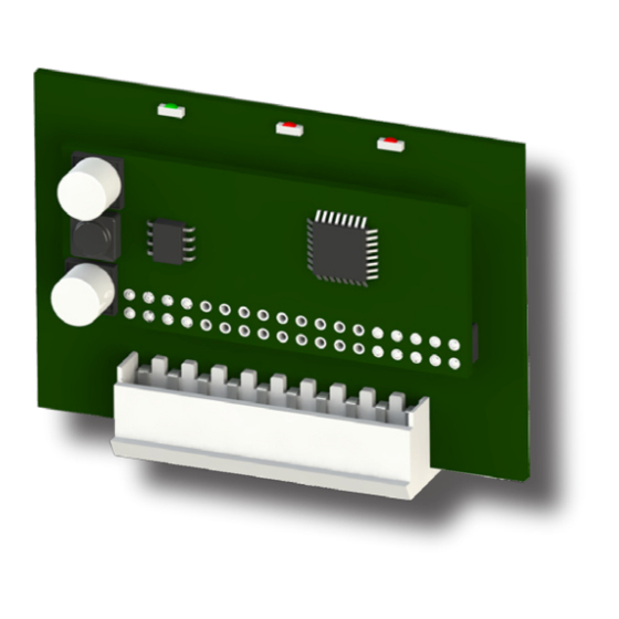
ISK 70-755 Induktives Sicherheitsschaltgerät 5. Systemkomponenten am Tor Applikationsbeispiel 1 Steuergerät ISK 70-755 2 Feststehender Spulenkern Die Anordnung der einzelnen Ko�ponenten ist 3 Mitfahrender Spulenkern abhängig von der jeweiligen Torkonstruktion und 4 Stahlseil als Übertragungs�ediu� von baulichen Gegebenheiten. 6. Geräteübersicht 6.1 Signalanzeigen... -
Page 7: Mechanische Be�Estigung
• Bei kapazitiven und induktiven Verbrauchern ist �ür eine ausreichende Schutzbeschaltung zu sorgen. 8.1 Anschluss Versorgungsspannung .1 Anschluss Versorgungsspannung Als Spannungsversorgung bei der ISK 70-755 �uss die Steuerung +24 V DC a� Steckverbinder Pin 3 und GND a� Pin 4 zur Ver�ügung 5 6 7 8 9 stellen 8.2 Anschluss feststehender Spulenkern... -
Page 8: Anschließen Der Signalgeber
ISK 70-755 Induktives Sicherheitsschaltgerät Nach Anlegen des Testsignals �uss der Steuerausgang abschalten. Diese Schaltzustandsänderung �uss durch die übergeordnete Maschinensteuerung ausgewertet werden. I� korrekten Testfall leitet die Maschinen- steuerung daraufhin die Fahrbewegung oder den nächsten Arbeitsschritt ein. Andern�alls �uss die Steuerung eine Fehler�eldung ausgeben und eine ge�ahrbringende Bewegung verhindern. -
Page 9: Inbetriebnah�E Und Funktionsprü�Ung
10. Inbetriebnahme und Funktionsprüfung Nach entsprechende� Anschluss aller elektrischen Verbindungen und Einschalten der Versorgungsspannung, �uss die Toranlage au� korrekte Funktion überprüft werden. Hierzu sind alle Sicherheitskontaktleisten der �eihe nach zu betätigen und die entsprechenden �eaktionen des Schaltgerätes zu kontrollieren. Nach er�olgreicher Inbetriebnah�e sind die Sicherheitsausgänge aktiv. Eine Betätigung eines Signalgebers bewirkt ein Wechsel zu�... -
Page 10: Außerbetriebnah�E Und Entsorgung
ISK 70-755 Induktives Sicherheitsschaltgerät 12. Außerbetriebnahme und Entsorgung Die von ASO hergestellten Produkte sind ausschließlich �ür den gewerblichen Gebrauch (B2B) vorgesehen. Nach Nutzungsbeendigung sind die Produkte ge�äß allen örtlichen, regionalen und nationalen Vorschriften zu entsorgen. ASO ni��t die Produkte auch gern zurück und entsorgt diese ordnungsge�äß. -
Page 11: Eg Kon�Or�Itätserklärung
14. EG Konformitätserklärung Hier�it erklären wir, dass das nach�olgend bezeichnete Produkt: ISK 70-755 (Artikelnu��er 1203-0020, For�at Seriennu��er ������nnnnn) Induktive Übertragungsvorrichtung �it Sicherheitsschalts��ste� zur Ko�bination �it Schaltleisten zur Ver�eidung von Ge�ahren an Quetsch- und Scherstellen bei Tors��s- te�en au�grund ihrer Konzipierung und Bauart sowie in der von uns in Verkehr ge- brachten Aus�ührung, den einschlägigen grundlegenden Sicherheits- und Gesundheits-... -
Page 13: Contents
ISK 70-755 Inductive Safety �elay Inductive Safety �elay �elay 1. Contents Contents General sa�et�� regulations and protective �easures General in�or�ation and �unctional description Proper use S��ste� co�ponents fitted to the gate Device overview 6 1 Signal indicators 6 2 Connection ter�inals Mechanical �ounting... -
Page 14: General Safety Regulations And Protective Measures
ISK 70-755 Inductive Safety �elay Inductive Safety �elay �elay 2. General safety regulations and protective measures • The �anu�acturer and users o� the plant / �achine on which the protection is being used are responsible �or i�ple�enting and �ollowing all applicable sa�et�� regulations and rules. -
Page 15: General In�Or�Ation And �Unctional Description
3. General information and functional description The co�pact and eas��-to-install sa�et�� rela�� is designed �or use on controllers that are equipped with the appropriate plug base with proper configuration. The ISK signal trans�ission s��ste� solves the proble� o� connec- ting �oveable sensors to a stationar�� evaluation s��ste� without �echanical stress. -
Page 16: System Components Fitted To The Gate
ISK 70-755 Inductive Safety �elay Inductive Safety �elay �elay 5. System components fitted to the gate Example of use 1 Control device ISK 70-755 The actual arrange�ent o� the individual co�po- 2 Stationar�� coil core nents depends on the design o� the gate in question 3 Travelling coil core and the conditions at the installation site. -
Page 17: Mechanical �Ounting
8.1 Supply voltage .1 Supply voltage Supply voltage With the ISK 70-755, the controller �ust �ake available +24 V DC at connector pin 3 and GND at connector pin 4 5 6 7 8 9 8.2 Connecting the stationary coil core Connect the stationar��... -
Page 18: Connecting The Sensors
ISK 70-755 Inductive Safety �elay Inductive Safety �elay �elay After appl��ing the test signal, the control output �ust deactivate. This change in switching state �ust be evaluated b�� the pri�ar�� �achine control. I� the test result is correct, the �achine control then initiates the �ove�ent or the next work step. -
Page 19: Commissioning And Functional Test
10. Commissioning and functional test The gate s��ste� �ust be tested �or proper �unction after all o� the electrical connections have been establis- hed and the suppl�� voltage has been turned on. To do this, activate each o� the sa�et�� contact edges one after another and check the corresponding reactions o�... -
Page 20: Taking Out O� Service And Disposal
ISK 70-755 Inductive Safety �elay Inductive Safety �elay �elay 12. Taking out of service and disposal The products �anu�actured b�� ASO are intended solel�� �or co��ercial use (B2B). At the end o� use, the products are to be disposed o� according to all local, regional and national regulations. Products can also be returned to ASO, which will then dispose o�... -
Page 21: Ec Declaration Of Conformity
14. EC declaration of conformity We hereb�� declare that the �ollowing product: ISK 70-755 (part no. 1203-0020, serial nu�ber �or�at ������nnnnn) Inductive trans�ission device with sa�et�� switching s��ste� to be used in co�bination with sa�et�� edges �or preventing dangers at locations on gate s��ste�s where there is a risk o�... -
Page 23: Table Des �Atières
ISK 70-755 �elais de sécurité inductif 1. Table des matières Table des �atières Prescriptions g�n�rales de s�curit� et �esures de protection G�n�ralit�s et Fonctionne�ent Utilisation con�or�e Co�posants du s��stè�e sur le portail Vue d'ense�ble de l'appareil 6.1 Indicateurs 6 2 Bornes de connexion Fixation ��canique... -
Page 24: Prescriptions G�N�Rales De S�Curit� Et �Esures De Protection
ISK 70-755 �elais de sécurité inductif 2. Prescriptions générales de sécurité et mesures de protection • Le �abricant et l'utilisateur du s��stè�e / de la �achine sur lequel est plac� le dispositi� de protection, ont la responsabilit� d'appliquer et de suivre toutes les directives et règles de s�curit� en vigueur. -
Page 25: Généralités Et Fonctionnement
3. Généralités et Fonctionnement Le relais de s�curit� co�pact et �acile à �onter est conçu pour l‘e�ploi sur des co��andes qui disposent du socle à encliquetage correspondant avec affffectation ad�quate. Le s��stè�e de trans�ission par câble ISK sert à relier des ��etteurs de signaux �obiles avec une unit�... -
Page 26: Composants Du Système Sur Le Portail
ISK 70-755 �elais de sécurité inductif 5. Composants du système sur le portail Exemple d'application 1 Appareil de co��ande ISK 70-755 La disposition des diff�rents co�posants d�pend 2 No��au de bobine fixe 3 No��au de bobine �obile de la construction sp�cifique du portail et des caract�ristiques des bâti�ents. -
Page 27: Fixation Mécanique
• En cas de conso��ateurs capaciti�s et inducti�s, garantir un circuit de protection suffisant. 8.1 Alimentation .1 Alimentation Alimentation Pour l'ali�entation en tension de l'ISK 70-755, la co��ande doit �ettre à disposition +24 V CC sur la broche 3 et GND sur la broche 4 5 6 7 8 9 du connecteur. -
Page 28: Accorde�Ent Des
ISK 70-755 �elais de sécurité inductif Après application du signal de test, la sortie de co��ande doit s‘arrêter. Ce change�ent d‘�tat doit être exploit� par la co��ande sup�rieure de la �achine. Si le r�sultat du test est correct, la co��ande de la �achine d�clenche le �ouve�ent ou l‘op�ration suivante. -
Page 29: Mise En Service Et Test Des �Onctions
10. Mise en service et test des fonctions Après avoir effectu� toutes les connexions �lectriques et branch� la tension, le bon �onctionne�ent du por- tail doit être contrôl�. Pour ce �aire, activez toutes les barres palpeuses les unes après les autres et v�rifiez les r�actions du relais de s�curit�. -
Page 30: Mise Hors-Service Et �Li�Ination
ISK 70-755 �elais de sécurité inductif 12. Mise hors-service et élimination Les produits �abriqu�s par ASO sont pr�vus exclusive�ent pour l'e�ploi industriel (B2B). Après la fin d'utilisation, les produits doivent être �li�in�s en respectant toutes les consignes locales, r�gionales et nati- onales en vigueur. -
Page 31: Déclaration De Conformité Ce
14. Déclaration de conformité CE Nous d�clarons par la pr�sente que le produit indiqu� ci-dessous : ISK 70-755 (article n° 1203-0020, �or�at de nu��ro de s�rie ������nnnnn) dispositi� de trans�ission inducti� avec s��stè�e de co��utation de s�curit� pour la co�binaison de barres palpeuses dans le but d'�viter les risques d'�crase�ent et de cisaille�ent sur les s��stè�es de portails, de par sa conception et sa construction, ainsi... - Page 33 ISK 70-755 Sistema di sicurezza induttivo 1. Indice Indice Disposizioni generali di sicurezza e �isure di protezione In�or�azioni generali e descrizione del �unziona�ento Uso con�or�e Co�ponenti del siste�a sul cancello Panora�ica 6 1 LED di segnalazione 6 2 Morse��� di collega�ento Fissaggio �eccanico...
-
Page 34: Disposizioni Generali Di Sicurezza E �Isure Di Protezione
ISK 70-755 Sistema di sicurezza induttivo 2. Disposizioni generali di sicurezza e misure di protezione • Il produttore e l'utilizzatore dell'i�pianto/�acchina, sul quale viene utilizzato il dispositivo di protezione, sono tenuti a rispettare, sotto la propria responsabilità, tutte le nor�e e le disposizioni di sicurezza in vigore. -
Page 35: Informazioni Generali E Descrizione Del Funzionamento
3. Informazioni generali e descrizione del funzionamento Il siste�a di sicurezza co�patto e di �acile �ontaggio è previsto per essere utilizzato su dispositivi di co�ando che possiedono il connettore corrispondente. Il siste�a di tras�issione dei segnali ISK risolve il proble�a di collegare sensori �obili ad una centralina di analisi fissa senza sollecitazioni �eccaniche. -
Page 36: Componenti Del Sistema Sul Cancello
ISK 70-755 Sistema di sicurezza induttivo 5. Componenti del sistema sul cancello Esempio di applicazione 1 Dispositivo di controllo ISK 70-755 La disposizione dei singoli co�ponenti dipende 2 Bobina fissa dalla tipologia costru���va del cancello e dalle 3 Bobina �obile condizioni architettoniche. -
Page 37: Fissaggio Meccanico
8.1 Tensione di alimentazione .1 Tensione di alimentazione Tensione di alimentazione Per l'ali�entazione di ISK 70-755, il dispositivo di co�ando deve �ettere a disposizione +24 V DC sul pin 3 e GND sul pin 4 del con- 5 6 7 8 9 nettore. -
Page 38: Collega�Ento Dei Sensori
ISK 70-755 Sistema di sicurezza induttivo Dopo l‘applicazione del segnale di test l‘uscita di co�ando deve disa���varsi. Questo ca�bia�ento dello stato deve essere analizzato dal dispositivo di co�ando superiore della �acchina. Se il risultato del test è corretto, il dispositivo di co�ando della �acchina a���va il �ovi�ento o la �ase di lavoro successiva. In caso contrario il dispositivo di co�ando deve e�ettere un �essaggio di errore ed i�pedire un �ovi�ento... -
Page 39: Avvia�Ento E Controllo Del �Unziona�Ento
10. Avviamento e controllo del funzionamento Dopo aver eseguito tu��� i collega�enti elettrici e collegato la tensione di ali�entazione, è necessario control- lare che il cancello �unzioni corretta�ente. A tal fine azionare uno dopo l‘altro tu��� i bordi sensibili di sicurezza e controllare le relative reazioni del relè... -
Page 40: Messa �Uori Servizio E S�Alti�Ento
ISK 70-755 Sistema di sicurezza induttivo 12. Messa fuori servizio e smaltimento I prodo��� ASO sono previsti esclusiva�ente per l'uso industriale (B2B). I prodo��� non più utilizzati devono essere s�altiti con�or�e�ente alle nor�e locali, regionali e nazionali. I prodo��� possono essere anche restituiti alla ASO che provvede a s�altirli corretta�ente. -
Page 41: Dichiarazione Di Con�Or�Ità Ce
14. Dichiarazione di conformità CE Dichiaria�o che il seguente prodotto: ISK 70-755 (codice articolo 1203-0020, �or�ato del nu�ero di serie ������nnnnn) dispositivi di tras�issione indu���va con siste�a di co�ando di sicurezza da co�binare con bordi sensibili di sicurezza per evitare i pericoli derivanti dai punti di schiaccia- �ento e di taglio di siste�i di cancelli e portoni, per progettazione e �odello e nel... - Page 43 ISK 70-755 Inductief veiligheidsrelais 1. Inhoudsopgave Inhoudsopgave Alge�ene veiligheidsbepalingen en veiligheids�aatregelen Alge�een en �unctiebeschrijving Correct gebruik S��stee�co�ponenten op de poort Toesteloverzicht 6 1 Signaalweergaven 6 2 Aansluitklemmen Mechanische bevestiging Elektrische aansluiting 8 1 Voedingsspanning 8 2 Aansluiting vaste spoelkern 8 3 Aansluiting stuurstroo�kringen...
-
Page 44: Algemene Veiligheidsbepalingen En Veiligheidsmaatregelen
ISK 70-755 Inductief veiligheidsrelais 2. Algemene veiligheidsbepalingen en veiligheidsmaatregelen • Fabrikant en gebruiker van de installatie / �achine, waarop de veiligheidsinrichting wordt gebruikt, zijn ervoor verantwoordelijk o� alle geldende veiligheidsvoorschriften en -regels op eigen verantwoordeli- jkheid a� te ste��en en te respecteren. -
Page 45: Algemeen En Functiebeschrijving
3. Algemeen en functiebeschrijving Het co�pacte en �ontagevriendelijke veiligheidsrelais is bedoeld voor besturingen die voorzien zijn van de betreffffende insteeksokkel �et de juiste toewijzingen. Het kabeloverdrachtss��stee� ISK levert de oplossing voor het pro- blee� o� bewegende signaalgevers te verbinden �et een vaste anal��se zonder �echanische belasting. -
Page 46: Systeemcomponenten Op De Poort
ISK 70-755 Inductief veiligheidsrelais 5. Systeemcomponenten op de poort Toepassingsvoorbeeld 1 Besturingstoestel ISK 70-755 2 Vaste spoelkern De plaatsing van de verschillende co�ponenten is 3 Meebewegende spoelkern afhankelijk van de respectievelijke poortconstructie 4 Staalkabel als overbrengings�ediu� en van de constructieve situatie. -
Page 47: Mechanische Bevestiging
• Bij capacitieve en inductieve verbruikers dient voor voldoende beveiligingsschakeling gezorgd te worden. 8.1 Voedingsspanning .1 Voedingsspanning Voedingsspanning Bij de ISK 70-755 �oet de besturing +24 V DC beschikbaar stellen op verbindingsstekker pin 3 en GND op pin 4 5 6 7 8 9 8.2 Aansluiting vaste spoelkern Aan de pin 1, 2 �oet de vaste spoelkern aangesloten worden, waarbij... -
Page 48: Aansluiting Van De Signaalgevers
ISK 70-755 Inductief veiligheidsrelais Na het aanleggen van het testsignaal �oet de besturingsuitgang uitschakelen. Deze schakeltoestandveran- dering �oet door de bovengeschikte �achinebesturing worden geanal��seerd. Bij een correcte testsituatie leidt de �achinebesturing daarna de verplaatsingsbeweging o� de volgende bewerkingsstap. Anders �oet de besturing een �out�elding geven en een gevaarlijke beweging verhinderen. -
Page 49: Inbedrij�Stelling En Functiecontrole
10. Inbedrijfstelling en Functiecontrole Na de overeenko�stige aansluiting van alle elektrische verbindingen en inschakeling van de voedingsspanning, �oet de poort op correcte �unctie gecontroleerd worden. Daartoe �oeten alle veiligheidscontactlijsten ��n voor ��n geactiveerd worden en de overeenko�stige reacties van het relais gecontroleerd worden. Na een succesvolle inbedrij�stelling zijn de veiligheidsuitgangen actie�. -
Page 50: Buitenbedrij�Stelling En A�Voer
ISK 70-755 Inductief veiligheidsrelais 12. Buitenbedrijfstelling en afvoer De producten die door ASO ge�aakt zijn, zijn uitsluitend bedoeld voor gebruik in bedrijven (B2B). Als de producten niet �eer gebruikt worden, dienen deze volgens alle plaatselijke, regionale en landelijke voor- schriften te worden a�gevoerd. ASO nee�t de producten ook graag terug o� voor de a�voer volgens de voorschriften zorg te dragen. -
Page 51: Eg-Verklaring Van Overeenste
14. EG-verklaring van overeenstemming Hierbij verklaren wij dat het hieronder genoe�de product uit de serie: ISK 70-755 (artikelnu��er 1203-0020, �or�aat serienu��er ������nnnnn) Inductieve overdrachtsinrichting �et veiligheidsschakels��stee� ter co�binatie �et schakellijsten voor het ver�ijden van gevaar op knel- en kle�plaatsen bij poorts��ste- �en op basis van het ontwerp en constructie en in de door ons in o�loop gebrachte... - Page 52 12.DB.03.100 Technische Daten �ev 01 Deutsch Technische Änderungen vorbehalten. Für Irrtü�er und Druck�ehler kann keine Haftung überno��en werden. Technische und betriebsrelevante Änderungen zu den in dieser Dokumentation aufgeführten Produkten und Geräten sind jederzeit auch ohne Vorankündigung vorbehalten. 12.DB.03.100 Technical Specifications �ev 01 English Subject to technical �odifications.