Table des Matières
Publicité
Les langues disponibles
Les langues disponibles
Liens rapides
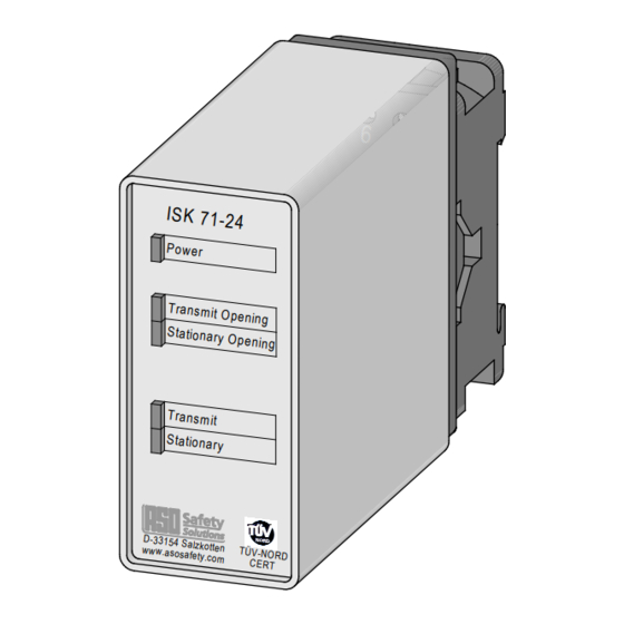
ISK 71-24
ISK 71-94
Betriebsanleitung (Original)
ISK 71‑24 + ISK 71‑94 Induktives Sicherheitsschaltgerät
Operating Manual
ISK 71‑24 + ISK 71‑94 Inductive Safety Relay
Manuel d'utilisation
ISK 71‑24 + ISK 71‑94 Relais de s�curit� �� induction
Manuale di istruzione
ISK 71‑24 + ISK 71‑94 Sistema di sicurezza induttivo
Gebruiksaanwijzing
ISK 71‑24 + ISK 71‑94 Inductief Veiligheidsschakelrelais Pagina 43‑51
Relay
de s�curit� �� induction
�� induction
Seite 3‑11
Page 13‑21
Page 23‑31
Pagina 33‑41
Publicité
Chapitres
Table des Matières

Manuels Connexes pour ASO Safety Solutions ISK 71-24


Sommaire des Matières pour ASO Safety Solutions ISK 71-24
- Page 1 ISK 71-24 ISK 71-94 Betriebsanleitung (Original) ISK 71‑24 + ISK 71‑94 Induktives Sicherheitsschaltgerät Seite 3‑11 Operating Manual Page 13‑21 ISK 71‑24 + ISK 71‑94 Inductive Safety Relay Relay Manuel d’utilisation ISK 71‑24 + ISK 71‑94 Relais de s�curit� �� induction de s�curit�...
- Page 2 Übergabedokumentation / Documentation / Documentation de datation / Documentazione di consegna / Documentatie Anlagenbeschreibung / Description / Description du système / Descrizione impianto / Beschrijving van de installatie Anlagenart / Type of plant / Sorte du système / Tipo d’impianto / Type installatie Hersteller / Manufacturer / Fabricant / Produttore / Fabrikant Seriennummer / Serial number / Num�ro de s�rie / Numero di serie / Seriennummer Datum der Inbetriebnahme / Commissioning date / Date de mise en marche / Data della messa in...
-
Page 3: Table Des Matières
ISK 71-24 + ISK 71-94 Induktives Sicherheitsschaltgerät Inhaltsverzeichnis Inhaltsverzeichnis ....3 Allgemeine Sicherheitsbestimmungen und Schutzmaßnahmen ....4 Allgemeines . -
Page 4: Allgemeine Sicherheitsbestimmungen Und Schutzmaßnahmen
ISK 71-24 + ISK 71-94 Induktives Sicherheitsschaltgerät 2. Allgemeine Sicherheitsbestimmungen und Schutzmaßnahmen • Hersteller und Benutzer der Anlage / Maschine, an der die Schutzeinrichtung verwendet wird, sind dafür verantwortlich, alle geltenden Sicherheitsvorschriften und ‑regeln in eigener Verant‑ wortung abzustimmen und einzuhalten. -
Page 5: Allgemeines
3. Allgemeines Das Seilübertragungssystem ISK löst die Problematik, bewegliche Signalgeber mit einer stationären Auswertung ohne mechanische Belastung zu verbinden. Die Kommunikation zwischen den beweglichen Signalgebern und der Auswertelektronik beruht hierbei auf induktiver Basis. Die Über‑ wachungselektronik induziert hierfür eine Frequenz auf einen Spulenkern, der in eine geschlossene Leiterschleife eingebunden ist. -
Page 6: Systemkomponenten Am Tor
ISK 71-24 + ISK 71-94 Induktives Sicherheitsschaltgerät 6. Systemkomponenten am Tor 3 11 10 1 2 Applikationsbeispiel 1 Steuergerät ISK 71‑24 (ISK 71‑94) 2 Feststehender Spulenkern Die Anordnung der einzelnen Komponenten ist 3 Mitfahrender Spulenkern abhängig von der jeweiligen Torkonstruktion 4 Stahlseil als Übertragungsmedium... -
Page 7: Anschluss Des Gerätes
Als Spannungsversorgung ist bei der ISK 71‑24 und der ISK 71‑94 an dem Klemmenpaar 8, 9 24V AC/DC anzuschließen. 8.3 Anschluss ortsfester Spulenkern ISK 71-24: An das Klemmenpaar 1, 2 ist der ortsfeste Spulenkern anzuschließen, wobei die Polarität beliebig ist. ‑... -
Page 8: Anschließen Der Mitfahrenden Signalgeber
ISK 71-24 + ISK 71-94 Induktives Sicherheitsschaltgerät 9. Anschließen der Signalgeber 9.1 Anschluss am Spulenkern (Bild 1) Die mitfahrenden Leisten (SKL) werden mit dem mitfahrenden Spulenkern verbunden. Hierzu wird die mitfahrende SKL ZU Bewegung mit dem Anschluss C des mitfahrenden Spulenkerns verbunden und die optionale SKL AUF Bewegung mit dem Anschluss O. -
Page 9: Fehlerdiagnose
11. Fehlerdiagnose Bei korrekter Verdrahtung und Anlegen der Versorgungsspannung darf nur die grüne LED leuchten. Bei Aufleuchten einer der roten LED‘s ist ein Fehler im System vorhanden, der sich mit Hilfe der LED eingrenzen lässt. Fehler Fehlerbeseitigung LED‘s Versorgungsspannung fehlt, zu gering Anschlüsse und Versorgungsspannung überprüfen: leuchten nicht oder falsch angeschlossen ‑ 24 V AC/DC an Klemmen 8 9... -
Page 10: Außerbetriebnahme Und Entsorgung
ISK 71-24 + ISK 71-94 Induktives Sicherheitsschaltgerät 12. Außerbetriebnahme und Entsorgung Die von ASO hergestellten Produkte sind ausschließlich für den gewerblichen Gebrauch (B2B) vorgesehen. Nach Nutzungsbeendigung sind die Produkte gemäß allen örtlichen, regionalen und nationalen Vorschriften zu entsorgen. ASO nimmt die Produkte auch gern zurück und entsorgt diese ordnungsgemäß. -
Page 11: Eg Konformitätserklärung
14. EG Konformitätserklärung Hiermit erklären wir, dass die nachfolgend bezeichneten Produkte der Baureihe: ISK 71-24 (Artikelnummer 204600, Format Seriennummer yymmnnnnn) ISK 71-94 (Artikelnummer 204610, Format Seriennummer yymmnnnnn) Induktive Übertragungsvorrichtung mit Sicherheitsschaltsystem zur Kombina‑ tion mit Schaltleisten zur Vermeidung von Gefahren an Quetsch‑ und Scher‑... - Page 13 ISK 71-24 + ISK 71-94 Inductive Safety Relay Contents Contents..... . . 13 General safety regulations and protective measures 14 General .
-
Page 14: General Safety Regulations And Protective Measures
ISK 71-24 + ISK 71-94 Inductive Safety Relay 2. General safety regulations and protective measures • The manufacturer and users of the plant / machine on which the protection is being used are responsible for implementing and following all applicable safety regulations and rules. -
Page 15: General
3. General The ISK signal transmission system solves the problem of connecting moveable sensors to a stationary evaluation system without mechanical stress. Communication between the moveable sensors and the electronic evaluation system is based on induction. To achieve this, the monitoring electronics induce a frequency on a coil core, which is integrated in a closed conductor loop. -
Page 16: System Components Fitted To The Gate
ISK 71-24 + ISK 71-94 Inductive Safety Relay 6. System components fitted to the gate 3 11 10 1 2 Example of use 1 control device ISK 71‑24 (ISK 71‑94) 2 Stationary coil core The actual arrangement of the individual 3 Travelling coil core components depends on the design of the... -
Page 17: Connecting The Device
With the ISK 71‑24 and ISK 71‑94, 24 V AC/DC is to be connected to terminal pair 8, 9 as voltage supply. 8.3 Connecting the stationary coil core ISK 71-24: Connect the stationary coil core to terminal pair 1, 2; no special attention is required for polarity. ‑... -
Page 18: Connecting The Travelling Sensors
ISK 71-24 + ISK 71-94 Inductive Safety Relay 9. Connecting the sensors 9.1 Connecting to the coil core (figure 1) The travelling edges (SCE) are connected to the travelling coil core. For this purpose, the travelling SCE CLOSING movement is connected to connection C of the travelling coil core and the optional SCE OPENING movement is connected to connection O. -
Page 19: Error Diagnosis
11. Error diagnosis Only the green LED may illuminate if the supply voltage has been correctly connected. If one of the red LEDs illuminate, there is an error in the system which can be pinpointed with the aid of the LED. Error Error correction LEDs are not ... -
Page 20: Taking Out Of Service And Disposal
ISK 71-24 + ISK 71-94 Inductive Safety Relay 12. Taking out of service and disposal The products manufactured by ASO are intended solely for commercial use (B2B). At the end of use, the products are to be disposed of according to all local, regional and national regulations. Products can also be returned to ASO, which will then dispose of them properly. -
Page 21: Ec Declaration Of Conformity
14. EC declaration of conformity We hereby declare that the following products of type series: ISK 71-24 71-24 (part no. 204600, serial number format yymmnnnnn) ISK 71-94 71-94 (part no. 204610, serial number format yymmnnnnn) Inductive transmission device with safety switching system to be used in com‑... -
Page 23: Relais De Sécurité Inductif
ISK 71-24 + ISK 71-94 Relais de sécurité inductif Table des matières Table des matières ....23 Prescriptions g�n�rales de s�curit� et mesures de protection ....24 G�n�ralit�s . -
Page 24: Isk 71-24 + Isk 71-94 Relais De Sécurité Inductif
ISK 71-24 + ISK 71-94 Relais de sécurité inductif 2. Prescriptions générales de sécurité et mesures de protection • Le fabricant et l'utilisateur du système / de la machine sur lequel est plac� le dispositif de pro‑ tection, ont la responsabilit� d'appliquer et de suivre toutes les directives et règles de s�curit�... -
Page 25: Généralités
3. Généralités Le système de transmission par câble ISK sert �� relier des �metteurs de signaux mobiles avec une unit� d'�valuation stationnaire sans contrainte m�canique. La communication entre les �metteurs de signaux mobiles et le système �lectronique d'�valuation est inductive. Le système �lectronique de surveillance induit pour cela une fr�quence sur un noyau de bobine int�gr�... -
Page 26: Composants Du Système Sur Le Portail
ISK 71-24 + ISK 71-94 Relais de sécurité inductif 6. Composants du système sur le portail 3 11 10 1 2 Exemple d'application 1 Appareil de commande ISK 71‑24 (ISK 71‑94) 2 Noyau de bobine fixe La disposition des diff�rents composants 3 Noyau de bobine mobile dépend de la construction spécifique du portail... -
Page 27: Raccordement De L'appareil
24 V CA/CC doivent être raccord�s �� la paire de bornes 8, 9. 8.3 Raccordement du noyau de bobine stationnaire ISK 71-24: Raccordez le noyau de bobine stationnaire �� la paire de bornes 1, 2, la polarit� n'ayant aucune importance. ‑... -
Page 28: Raccordement Des Émetteurs De Signaux
ISK 71-24 + ISK 71-94 Relais de sécurité inductif 9. Raccordement des émetteurs de signaux 9.1 Raccordement au noyau de bobine (figure 1) Les barres palpeuses mobiles (SKL) sont reli�es au noyau de bobine mobile. Pour cela, le mouvement de FERMETURE de la barre palpeuse mobile est raccord�... -
Page 29: Diagnostic D'erreurs
11. Diagnostic d'erreurs Si le câblage est correct, lors de la mise sous tension, seule la LED verte doit briller. Si une des LED rouges s'allume, il y a une erreur dans le système que la LED allum�e permet de localiser. Erreur Correction Les LED ne ... -
Page 30: Mise Hors-Service Et �Limination
ISK 71-24 + ISK 71-94 Relais de sécurité inductif 12. Mise hors-service et élimination Les produits fabriqués par ASO sont prévus exclusivement pour l'emploi industriel (B2B). Après la fin d'utilisation, les produits doivent être �limin�s en respectant toutes les consignes locales, r�gionales et nationales en vigueur. -
Page 31: Déclaration De Conformité Ce
14. Déclaration de conformité CE Nous d�clarons par la pr�sente que les produits suivants des s�ries : ISK 71-24 71-24 (article n° 204600, format de num�ro de s�rie yymmnnnnn) ISK 71-94 71-94 (article n° 204610, format de num�ro de s�rie yymmnnnnn) dispositifs de transmission inductifs avec système de commutation de s�cu‑... - Page 33 ISK 71-24 + ISK 71-94 Sistema di sicurezza induttivo Indice Indice ......33 Disposizioni generali di sicurezza e misure di protezione .
-
Page 34: Disposizioni Generali Di Sicurezza E Misure Di Protezione
ISK 71-24 + ISK 71-94 Sistema di sicurezza induttivo 2. Disposizioni generali di sicurezza e misure di protezione • Il produttore e l'utilizzatore dell'impianto/macchina, sul quale viene utilizzato il dispositivo di protezione, sono tenuti a rispettare, sotto la propria responsabilit��, tutte le norme e le disposizioni di sicurezza in vigore. -
Page 35: Generalit
3. Generalità Il sistema di trasmissione dei segnali ISK risolve il problema di collegare sensori mobili ad una centralina di analisi fissa senza sollecitazioni meccaniche. La comunicazione tra i sensori mobili e la centralina di controllo viene realizzata per via induttiva. A tal fine l'elettronica di sorveglianza induce una frequenza in una bobina interagente con un circuito chiuso. -
Page 36: Componenti Del Sistema Sul Cancello
ISK 71-24 + ISK 71-94 Sistema di sicurezza induttivo 6. Componenti del sistema sul cancello 3 11 10 1 2 Esempio di applicazione 1 Dispositivo di controllo ISK 71‑24 (ISK 71‑94) 2 Bobina fissa La disposizione dei singoli componenti dipende... -
Page 37: Collegamento Dell'apparecchio
Come alimentazione alla ISK 71‑24 ed alla ISK 71‑94 si devono collegare 24 V AC/DC alla coppia di morsetti 8, 9. 8.3 Collegamento della bobina fissa ISK 71-24: alla coppia di morsetti 1, 2 si deve collegare la bobina fissa, la polarità è qualsiasi. ISK 71-94: la bobina fissa deve essere collegata al connettore ‑... -
Page 38: Collegamento Dei Sensori Mobili
ISK 71-24 + ISK 71-94 Sistema di sicurezza induttivo 9. Collegamento dei sensori 9.1 Collegamento alla bobina (figura 1) I bordi mobili (BSS) vengono collegati alla bobina mobile. A tal fine il BSS CHIUSURA mobile viene collegato ai morsetti C della bobina mobile ed il BSS APERTURA opzionale ai morsetti O. -
Page 39: Diagnosi Anomalie
11. Diagnosi anomalie Se il cablaggio è corretto e la tensione di alimentazione è applicata, deve accendersi solo il LED verde. Se si accende uno dei LED rossi, significa che nel sistema è presente un'anomalia che può essere individuata almeno approssimativamente mediante i LED. Anomalia Eliminazione anomalie I LED non si ... -
Page 40: Messa Fuori Servizio E Smaltimento
ISK 71-24 + ISK 71-94 Sistema di sicurezza induttivo 12. Messa fuori servizio e smaltimento I prodotti ASO sono previsti esclusivamente per l'uso industriale (B2B). I prodotti non più utilizzati devono essere smaltiti conformemente alle norme locali, regionali e nazionali. I prodotti possono essere anche restituiti alla ASO che provvede a smaltirli correttamente. -
Page 41: Dichiarazione Di Conformit
14. Dichiarazione di conformità CE Dichiariamo che i seguenti prodotti della serie: ISK 71-24 71-24 (codice articolo 204600, formato del numero di serie yymmnnnnn) ISK 71-94 71-94 (codice articolo 204610, formato del numero di serie yymmnnnnn) dispositivi di trasmissione induttiva con sistema di comando di sicurezza da... - Page 43 ISK 71-24 + ISK 71-94 Inductief veiligheidsrelais Inhoudsopgave Inhoudsopgave ....43 Algemene veiligheidsbepalingen en veiligheids‑ maatregelen ....44 Algemeen .
-
Page 44: Algemene Veiligheidsbepalingen En Veiligheidsmaatregelen
ISK 71-24 + ISK 71-94 Inductief Veiligheidsschakelrelais 2. Algemene veiligheidsbepalingen en veiligheidsmaatregelen • Fabrikant en gebruiker van de installatie / machine, waarop de veiligheidsinrichting wordt gebru‑ ikt, zijn ervoor verantwoordelijk om alle geldende veiligheidsvoorschriften en ‑regels op eigen verantwoordelijkheid af te stemmen en te respecteren. -
Page 45: Algemeen
3. Algemeen Het kabeloverdrachtssysteem ISK levert de oplossing voor het probleem om bewegende signaalgevers te verbinden met een stationaire analyse zonder mechanische belasting. De communicatie tussen de bewegende signaalgevers en de analyse‑elektronica berust hierbij op een inductieve basis. De bewakingselektronica induceert hiertoe een frequentie op een spoelkern die in een gesloten geleidende lus geïntegreerd is. -
Page 46: Systeemcomponenten Op De Poort
ISK 71-24 + ISK 71-94 Inductief Veiligheidsschakelrelais 6. Systeemcomponenten op de poort 3 11 10 1 2 Toepassingsvoorbeeld 1 Besturingstoestel ISK 71‑24 (ISK 71‑94) 2 Vaste spoelkern De plaatsing van de verschillende componenten 3 Meebewegende spoelkern is afhankelijk van de respectievelijke poortcons‑... -
Page 47: Aansluiting Van Het Toestel
Als voeding moet bij de ISK 71‑24 en de ISK 71‑94 op elk klemmen‑ paar 8, 9 24 V AC/DC aangesloten worden. 8.3 Aansluiting vaste spoelkern ISK 71-24: Aan het klemmenpaar 1, 2 moet de vaste spoelkern aangesloten worden, waarbij de polariteit om het even is. ‑... -
Page 48: Aansluiting Van De Signaalgevers
ISK 71-24 + ISK 71-94 Inductief Veiligheidsschakelrelais 9. Aansluiting van de signaalgevers 9.1 Aansluiting aan de spoelkern (afbeelding 1) De meebewegende lijsten (SKL's) worden met de meebewegende spoelkern verbonden. Hiertoe dient de meebewegende SKL DICHT‑bewe‑ ging met de aansluiting C van de meebewegende spoelkern en de optionele SKL OPEN beweging met de aansluiting O verbonden te worden. -
Page 49: Foutendiagnose
11. Foutendiagnose Bij een correcte bedrading en aansluiting van de voedingsspanning mag enkel de groene LED branden. Wanneer ��n van de rode LED's oplicht, zit er in het systeem een fout, die met behulp van de LED's kan worden opgespoord. Fout Verhelping van de fout LED's branden ... -
Page 50: Buitenbedrijfstelling En Afvoer
ISK 71-24 + ISK 71-94 Inductief Veiligheidsschakelrelais 12. Buitenbedrijfstelling en afvoer De producten die door ASO gemaakt zijn, zijn uitsluitend bedoeld voor gebruik in bedrijven (B2B). Als de producten niet meer gebruikt worden, dienen deze volgens alle plaatselijke, regionale en landelijke voorschriften te worden afgevoerd. -
Page 51: Eg-Verklaring Van Overeenstemming
14. EG-verklaring van overeenstemming Hierbij verklaren wij dat de hieronder genoemde producten uit de serie: ISK 71-24 71-24 (artikelnummer 204600, formaat serienummer yymmnnnnn) ISK 71-94 71-94 (artikelnummer 204610, formaat serienummer yymmnnnnn) Inductieve overdrachtsinrichting met veiligheidsschakelsysteem ter combinatie met schakellijsten voor het vermijden van gevaar op knel‑ en klemplaatsen... - Page 52 12.DB.04.001 Technische Daten Rev 06 Deutsch Technische Änderungen vorbehalten. Für Irrtümer und Druckfehler kann keine Haftung übernommen werden. 12.DB.04.001 Technical Specifications Rev 06 English Subject to technical modifications. No liability can be assumed for errors or misprints. 12.DB.04.001 Donn�es techniques R�v 06 Français Sous réserve de modifications techniques.