
Manuels Connexes pour Horizon Hobby HANGAR 9 Ultra Stick 10cc


Sommaire des Matières pour Horizon Hobby HANGAR 9 Ultra Stick 10cc
- Page 1 ™ Ultra Stick 10cc Instruction Manual Bedienungsanleitung Manuel d’utilisation Manuale di Istruzioni...
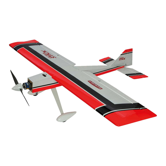
- Page 2 SPECIFICATIONS • SPEZIFIKATIONEN • SPÉCIFICATIONS • SPECIFICHE LARGE PARTS LAYOUT • BAUTEILE (OHNE KLEINTEILE) • GRANDES PIÈCES • SCHEMA DEI COMPONENTI GRANDI 60.0 in (1524 mm) 810 sq in (52.3 dm2) 57 in (1448 mm) 7.0 lbs (3.18 kg) 2-Stroke Gas: 10cc 2-Takt Benziner: 10cc 2 temps Essence: 10cc...
- Page 3 Part # English Deutsch Français Italiano REPLACEMENT PARTS • ERSATZTEILE • PIÈCES DE RECHANGE • PEZZI DI RICAMBIO HAN234501 Fuselage Rumpf Fuselage Fusoliera HAN234502 Wing with Ailerons and Flaps Flügel mit Querrudern und Klappen Aile avec ailerons et volets Ala con alettoni e fl...
- Page 4 Part # English Deutsch Français Italiano 2-STROKE GAS • 2-TAKT BENZINER • 2 TEMPS ESSENCE • 2-TEMPI A BENZINA APC12060 Sport Propeller, 12 x 6 Sportpropeller, 12 x 6 Hélice sport, 12 x 6 Elica sport, 12 x 6 Evolution, interruttore a 3 fi...
- Page 5 Part # English Deutsch Français Italiano REQUIRED TOOLS • BENÖTIGTES WERKZEUG • OUTILS REQUIS • ATTREZZI NECESSARI Box wrench: 1/2-inch Ringschlüssel: 1/2-inch Clé hexagonale: 1/2-inch Chiave esagonale: 1/2-inch Drill Bohrer Mini-perceuse Trapano Drill bit: 1/16-inch, 5/64-inch, 1/8-inch Punte per trapano: 1,5mm, 2mm, 3mm, 4mm, Bohrer: 1,5mm, 2mm, 3mm, 4mm, 4,5mm Forêt : 1,5mm, 2mm, 3mm, 4mm, 4,5mm 5/32-inch, 3/16-inch...
-
Page 6: Before Starting Assembly
Horizon Hobby, LLC. This manual contains instructions for safety, operation and maintenance. It is essential to read and follow all the instructions and warnings in the manual, prior to assembly, setup or use, in order to operate IMPORTANT: Rebind the radio system once all control throws are set. -
Page 7: Vor Dem Zusammenbau
Halten Sie lose Gegenstände die sich im Propeller verfangen können weg vom Propeller. Dieses gilt auch für Kleidung Alle Anweisungen, Garantien und anderen zugehörigen Dokumente können im eigenen Ermessen von Horizon Hobby, oder andere Objekte wie zum Beispiel Stifte oder Schraubendreher. -
Page 8: Avant De Commencer L'assemblage
être utilisé par des enfants sans la surveillance directe d’un adulte. N’essayez pas de modifi er ou d’utiliser ce produit avec des composants incompatibles hors des instructions fournies par Horizon Hobby, LLC. Ce manuel comporte des Si l’entoilage présente quelque plis, vous pouvez les lisser en utilisant le pistolet à air chaud (HAN100) et le gant instructions relatives à... - Page 9 • Se si trovano parti danneggiate, contattare il negozio da cui è stato acquistato. o alterare il prodotto in nessuna maniera al di fuori delle istruzioni fornite da Horizon Hobby, LLC. Questo manuale contiene le istruzioni per un funzionamento e una manutenzione sicuri. È fondamentale leggere e seguire tutte le Se si trovano delle pieghe nella ricopertura, si possono togliere usando una pistola ad aria calda (HAN100) e guanto per istruzioni e le avvertenze del manuale prima di montare, confi...
-
Page 10: Building Precautions
BUILDING PRECAUTIONS OPTIONAL FLOAT INSTALLATION HINWEISE ZUM BAU MONTAGE DER OPTIONALEN SCHWIMMER During assembly, we recommend resting the parts on a When installing the recommended fl oats on your Ultra Während des Zusammenbaus empfehlen wird, dass die soft surface such as a soft towel to help prevent denting Stick 10cc, make sure to use the parts listed under the Teile auf einer weichen Oberfl... -
Page 11: Précautions D'assemblage
PRÉCAUTIONS D’ASSEMBLAGE INSTALLATION DES FLOTTEURS PRECAUZIONI PER LA COSTRUZIONE INSTALLAZIONE DEL GALLEGGIANTE FACULTATIFS OPZIONALE Lors de l’assemblage de votre modèle, nous vous Durante l’assemblaggio noi consigliamo di appoggiare recommandons de poser les pièces sur une surface le varie parti su di una superfi... - Page 12 AILERON AND FLAP INSTALLATION Use side cutters to trim the screws. Remove the aileron and fl ap from the wing. Use a 5/64-inch (2mm) drill bit to clear the holes of any Use a fi le to lightly fi le any sharp points from the screws debris for the control horn mounting screws.
- Page 13 11. Install all three aileron hinges at this time. 16. Check the gap between the fl ap and aileron. Use a thin ruler (or similar) that is 1/16-inch (1.5mm) thick as a spacer so the gap between the ailerons and fl aps are the same.
- Page 14 20. Use a hobby knife and #11 blade to remove the covering 25. Apply a small amount of thin CA to harden the threads in the servo cover to the servo arm. made in the previous step. Allow the CA to fully cure before installing the aileron servo cover.
- Page 15 30. Enlarge the hole in the servo arm that is 5/8-inch 35. Tie or tape the string located inside the wing to the end (16mm) from the center of the servo. (Drawing is not to of the servo lead. scale). ...
- Page 16 40. Connect the clevis to the center hole of the control horn. 45. Use the radio system to set the fl ap to the down position. With the radio on and aileron servo centered, adjust the Use the radio to set the full defl ection position. link to center the aileron.
-
Page 17: Stabilizer Installation
50. Use a paper towel and isopropyl alcohol to remove the 54. Check the alignment of the stabilizer to the wing. It lines from the wing made by the felt-tipped pen. should be equal on both sides of the fuselage. 51. - Page 18 59. Use an epoxy brush to apply epoxy to the stabilizer 64. Use a hobby knife with a #11 blade to carefully remove mounting surface in the notch in the fuselage for the the covering 1/8-inch (3mm) inside the lines drawn from stabilizer.
- Page 19 69. Fit the fi n in position. Check that it is square to the 74. If the elevators are not in alignment, use pliers to bend fuselage. the joiner wire slightly to bring the halves into alignment. Continue the assembly of your model once the joiner wire has been correctly checked and adjusted.
- Page 20 79. Check to make sure you can install the hinges and joiner 84. Use a toothpick to apply epoxy to the stabilizer where it wire. The leading edge of the elevator will fi t tightly contacts the joiner wire. against the trailing edge of the stabilizer. 80.
- Page 21 89. Lightly sand the tail wheel wire where it contacts the 94. Prepare the hinge slots and hinges for the rudder. Install rudder. Use a paper towel and isopropyl alcohol to the hinges and fi t the rudder to the fi n. Align the top of remove any oil or debris from the wire.
- Page 22 RADIO INSTALLATION (OPTION 1) 103. Connect the clevis to the hole in the servo that is 5/8- 103. inch (16mm) from the center of the arm. (Drawing is not to scale). Make sure to remove any unused arms so they ...
- Page 23 RADIO INSTALLATION (OPTION 2) 113. Repeat the above steps to build and install the rudder 108. 113. pushrod. Use the included 8 -inch (210mm) pushrod for 108. Attach the control horn to the top of the elevator using the rudder in this step. the technique outlined for the aileron servos.
- Page 24 118. Attach the wheel pants to the landing gear using two M3 123. Use medium grit sandpaper to lightly sand the outside of 118. 123. x 10 button head screws and two M3 washers. Apply the pushrod tube so the CA will adhere to it. threadlock on the screws, then tighten using a 2mm hex wrench.
- Page 25 128. Remove the engine from the mounts. Use a drill and 133. Place a drop of threadlock on the screw, then install the 128. 133. 11/64-inch (4.5mm) drill bit to drill the holes for the M2 nut to secure the connector. The servo arm can then engine mounting screws.
- Page 26 138. Test fi t the spinner cone to the backplate. Make sure the 143. Mount the ignition module in the fuselage. Route the 138. 143. propeller does not contact the spinner cone when the spark plug cap through the hole in the fi rewall. Connect screws holes in the cone are aligned with the backplate.
- Page 27 148. Mount the switch for the ignition module on the side 153. Trim the covering inside the opening at the rear of the 148. 153. of the fuselage. Secure the lead from the switch to the hatch. The opening is used to remove the hatch to ignition module using the fastener included with the access the motor batteries and to allow cooling air into engine.
- Page 28 158. Place hook and loop tape on the battery tray and battery 163. Attach the spinner cone using the screws included with 158. 163. to prevent it from sliding on the tray during fl ight. Hook the spinner. Make sure the propeller does not contact and loop straps can be installed to secure the battery to the spinner cone.
- Page 29 OPTIONAL FLOAT INSTALLATION 173. Prepare the slot for the thicker front strut by removing 168. 173. the covering. When converting your model from fixed gear to floats, you must check the CG before flying your model. The floats will change the CG, requiring additional weight to the front of your model to properly balance it for flight.
- Page 30 178. Fit the cross brace into the mount on the fl oat without 178. the rudder. Fit both the front and rear cross braces, tightening the screws onto the fl at areas of the braces. 179. Slide the fl oat mounts on the struts. Tighten the screws 179.
-
Page 31: Center Of Gravity
CENTER OF GRAVITY CONTROL THROWS An important part of preparing the aircraft for fl ight is properly balancing the model. Turn on the transmitter and receiver of your model. Check the movement of the rudder using the transmitter. When the stick is moved to the right, the rudder should also move right. -
Page 32: Aerobatic Mixing
AEROBATIC MIXING PREFLIGHT CHECKLIST DAILY FLIGHT CHECKS The Ultra Stick 10cc is confi gured with separate aileron and fl ap servos which allows you to add a variety of mixes that • Charge the transmitter, receiver and motor battery for •... - Page 33 Product original sales receipt verifying the proof-of-purchase Horizon Hobby, LLC (Horizon) warrants to the original PROFITS OR PRODUCTION OR COMMERCIAL LOSS IN ANY in, please use the Horizon Online Service Request date.
-
Page 34: Warranty And Service Contact Information
Hanskampring 9 D 22885 Barsbüttel, Germany Sales: Horizon Hobby GmbH +49 (0) 4121 2655 100 INSTRUCTIONS FOR DISPOSAL OF WEEE BY USERS IN THE EUROPEAN UNION This product must not be disposed of with other waste. Instead, it is the user’s responsibility to dispose of their waste equipment by handing it over to a designated collections point for the recycling of waste electrical and electronic equipment. - Page 35 MONTAGE VON QUERRUDER UND KLAPPE Die Steuerhornrückplatte auf die Schrauben schieben. Mit einem Zahnstocher eine kleine Menge Querruder und Klappen vom Flügel entfernen. Kanzelkleber auf die Schrauben auftragen, dann die M2-Muttern auf die Schrauben drehen. Mit einem Nr. 1-Kreuzschlitzschraubendreher und einem 4 mm Steckschlüssel die Schrauben festziehen.
- Page 36 Sicherstellen, die Löcher für die Aufhängungen zu 12. Die vorherigen Schritte zur Montage der drei bohren. Die Löcher bieten dem CA-Klebstoff einen Tunnel, Aufhängungen der Klappe wiederholen. damit er vollständig in die Aufhängung fließen kann. Werden keine Löcher gebohrt, so kann dies dazu führen, dass die Aufhängungen nicht korrekt geklebt werden.
- Page 37 17. Sobald der CA-Klebstoff ausgehärtet ist, vorsichtig an 21. Prüfen, dass die Servohalterung sicher auf der der festen Fläche und der Steueroberfl äche ziehen, um Servoabdeckung geklebt ist. Ist die Halterung nicht sicherzustellen, dass die Aufhängungen sicher verklebt gesichert, eine kleine Menge des mittleren CA-Klebstoffs sind.
- Page 38 26. Die Hülsen und Ösen in den Servos montieren. Die 31. Den Servo mit einem Nr. 1-Kreuzschlitzschraubendreher dem Servo beigelegten Anweisungen befolgen. Zum und den mit dem Servo bereitgestellten Schrauben an jetzigen Zeitpunkt die Servos für Klappe und Querruder der Abdeckung sichern. vorbereiten.
- Page 39 36. Die Servoleitung an der Flügelwurzel holen. Die Leitung 41. Sobald das Ausrichten abgeschlossen ist, die durch das Loch in der Unterseite des Flügels führen. Gabelkopfhalter (Silikonrohr) über die Zinken der Gabelköpfe schieben, dann die Muttern gegen die Gabelköpfe festziehen. Gewindesicherung auf den Muttern verwenden, um ein Lösen unter Vibrationen zu verhindern.
-
Page 40: Montage Des Stabilisators
MONTAGE DER FLÜGEL 51. Eine kleine Menge 5-minütigen Epoxid auf das freiliegende Holz mit einem Pinsel auftragen. Die 46. Die Passstifte auf der Vorderkante des Flügels in die Flügelschraubenplatte in Position bringen und das Epoxid Löcher im Rumpf einpassen. vor dem Fortfahren vollständig aushärten lassen. - Page 41 55. Sämtliche Ausrichtungen überprüfen. Den Umriss des 60. Den Stabilisator wieder in seine ursprüngliche Position Rumpfs auf der Oberseite des Stabilisators markieren. einpassen. Die Ausrichtung des Stabilisators mittels der Schritte 1 bis 3 prüfen, dann ein Papiertuch und Isopropylalkohol verwenden, um überschüssiges Epoxid von Rumpf und Stabilisator zu entfernen.
- Page 42 65. Mit einem Hobbymesser mit einer Nr. 11-Klinge 70. Klebeband verwenden, um das Seitenleitwerk in Position vorsichtig die Abdeckung 3 mm (1/8 Zoll) innerhalb der zu halten, bis das Epoxid vollständig ausgehärtet gezogenen Linien von der Oberseite des Rumpfs auf dem ist. Die Position des Seitenleitwerks überprüfen, um vorderen Teil des Seitenleitwerks entfernen.
- Page 43 75. Mit einem Klebeband geringer Klebekraft ein 50 mm 79. Prüfen, um sicherzustellen, dass Aufhängungen und (2 Zoll) breites Stück durchsichtigem Kunststoff oder Verbinderkabel montiert werden können. Die Vorderkante Wachspapier um den Stabilisator gegen den Rumpf des Höhenruders wird bündig mit der Hinterkante des sichern.
- Page 44 84. Mit einem Zahnstocher das Epoxid auf den Stabilisator 89. Das Kabel des Spornrads leicht schleifen, wo es auftragen, wo er das Verbinderkabel berührt. das Seitenruder berührt. Mit einem Papiertuch und Isopropylalkohol Öl- oder Schmutzrückstände vom Draht entfernen. 85. Das verbleibende Höhenruder in seiner Position 90.
-
Page 45: Montage Des Funkgeräts (Option 1)
MONTAGE DES FUNKGERÄTS (OPTION 1) 94. Die Schlitze für die Aufhängungen und die Aufhängungen für das Seitenruder vorbereiten. Die Aufhängungen montieren und das Seitenruder in das Seitenleitwerk Zum Befestigen der Servos von Seiten- und einpassen. Die Oberseite von Seitenleitwerk und Querruder stehen zwei Optionen zur Verfügung. -
Page 46: Montage Des Funkgeräts (Option 2)
MONTAGE DES FUNKGERÄTS (OPTION 2) 103. Den Gabelkopf mit der Öffnung im Servo verbinden, die 103. 108. 16 mm (5/8 Zoll) von der Mitte des Arm entfernt liegt. 108. Das Steuerhorn auf der Oberseite der Höhenruder (Die Zeichnung ist nicht maßstabsgetreu). Sicherstellen, nach den für die Servos des Querruders aufgeführten jeden nicht verwendeten Arm zu entfernen, damit sie den Techniken anbringen. - Page 47 113. Die vorstehenden Schritte zum Zusammenbau und 118. Die Radverkleidung mit zwei M3 x 10 113. 118. Montieren des Rudergestänges verwenden. Das Rundkopfschrauben und zwei M3-Unterlegscheiben mitgelieferte 210 mm (8 Zoll) Gestänge für das am Fahrwerk anbringen. Gewindesicherung auf die Seitenruder in diesem Schritt verwenden. Schrauben auftragen, dann mit einem 2 mm Sechskant festziehen.
- Page 48 123. Mit Sandpapier mittlerer Körnung die Außenseite des 128. Den Motor aus der Halterung nehmen. Mit einem 123. 128. Gestängerohrs leicht schleifen, damit der CA-Klebstoff 4,5 mm (11/64 Zoll) Bohrer Löcher für die Schrauben der haften bleibt. Motorhalterung bohren. Die Halterungen abnehmen und mit einer Standbohrmaschine Löcher in die Motorhalterung bohren.
- Page 49 133. Einen Tropfen Gewindesicherung auf die Schraube 138. Den Spinnerkegel probeweise an der Rückplatte 133. 138. auftragen, dann die M2-Mutter zum Sichern des Steckers einpassen. Sicherstellen, dass der Propeller den montieren. Der Servoarm kann dann wieder auf dem Spinnerkegel nicht berührt, wenn die Schraubenlöcher Servo montiert werden.
- Page 50 143. Das Zündmodul im Rumpf montieren. Den 148. Den Schalter für das Zündmodul an der Seite des Rumpfs 143. 148. Zündkerzenstecker durch das Loch im Brandschott anbringen. Die Leitung vom Schalter zum Zündmodul mit verlegen. Die Leitung vom Motor mit der entsprechenden dem mit dem Motor mitgelieferten Befestiger sichern.
- Page 51 153. Die Abdeckung in der Öffnung am hinteren Teil der 158. Klettband auf Akku-Halterung und Akku platzieren, um 153. 158. Abdeckung trimmen. Die Öffnung wird zum Entfernen der ein Verrutschen auf der Halterung während des Flugs zu Abdeckung verwendet, um Zugang zu den Motor-Akkus verhindern.
-
Page 52: Montage Der Optionalen Schwimmer
163. Den Spinnerkegel mit den mit dem Spinner 167. Die Akkus mit dem Klettband im Rumpf sichern. Einen 163. 167. mitgelieferten Schrauben anbringen. Sicherstellen, Akku (Empfänger) für die EP-Version verwenden oder dass der Propeller den Spinnerkegel nicht berührt. Die zwei Akkus (Zündung und Empfänger) für die Montage Rückplatte erneut positionieren oder den Spinnerkegel mit Gas. - Page 53 171. Den Halteriemen abnehmen und mit einem 2 mm 176. Die Schwimmerverstrebung in den Schwimmern gemäß 171. 176. (5/64 Zoll) Bohrer Löcher für die Schrauben in den den Anweisungen des Schwimmersatzes anbringen. Die Rumpf bohren. Dabei für beiden Riemen bohren. Eine hintere Halterung entsprechend dem Foto positionieren. der Befestigungsschrauben in die Löcher drehen.
- Page 54 181. Mit einem Bastelmesser ein ausreichend großes Loch 181. schneiden, um die Servoleitung vom Schwimmer in den Rumpf zu führen. Mit Klebeband die Leitung an der hinteren Verstrebung sichern. Eine kleine Menge Silikonkleber oder Klebeband kann zum Abdichten des Lochs verwendet werden, durch das die Servoleitung in den Rumpf geführt wird.
-
Page 55: Der Schwerpunkt
DER SCHWERPUNKT RUDERAUSSCHLAG Ein wichtiger Teil bei der Vorbereitung des Flugzeugs für den Flug ist das ordnungsgemäße Ausbalancieren des Den Sender und Empfänger des Modells einschalten. Die Bewegung des Seitenruders mit der Fernsteuerung Modells. prüfen. Wird der Steuerhebel nach rechts bewegt, sollte sich auch das Seitenruder nach rechts bewegen. Die Richtung auf dem Servo am Empfänger bei Bedarf umkehren. -
Page 56: Täglicher Flug Check
MISCHUNG FÜR DEN KUNSTFLUG VORFLUGKONTROLLE TÄGLICHER FLUG CHECK Der Ultra Stick 10 cc verfügt über separate Servos für Querruder und Klappen, die eine Vielzahl von Mischungen • Laden Sie den Sender- ,Empfänger- und Zündakku • Überprüfen Sie die Spannung des Senderakkus. ermöglichen und zu einer erheblichen Verbesserung der Manövrierfähigkeit des Modells führen. -
Page 57: Garantie Und Service
Hinweise für die Wartung und den Betrieb des Produktes. obliegt einzig Horizon Hobby. Exklusive Garantie Horizon Hobby LLC (Horizon) Ausgeschlossen sind auch Fälle die bedingt durch (vii) Es ist unabdingbar, diese Hinweise vor der ersten Kostenpfl ichtige Reparaturen... -
Page 58: Garantie Und Service Kontaktinformationen
Horizon Technischer Service service@horizonhobby.eu Hanskampring 9 D 22885 Barsbüttel, Germany Sales: Horizon Hobby GmbH +49 (0) 4121 2655 100 ANWEISUNGEN ZUR ENTSORGUNG VON ELEKTRO- UND ELEKTRONIK-ALTGERÄTEN FÜR BENUTZER IN DER EUROPÄISCHEN UNION Dieses Produkt darf nicht zusammen mit anderem Abfall entsorgt werden. Stattdessen ist der Benutzer dafür verantwortlich, unbrauchbare Geräte durch Abgabe bei einer speziellen Sammelstelle für das... - Page 59 INSTALLATION DES AILERONS ET DES Utilisez une pince coupante pour tailler les vis. VOLETS Retirez l’aileron et le volet de l’aile. Utilisez une mèche de 2 mm (5/64 po) pour percer les Utilisez une lime pour limer légèrement tout bout pointu trous pour les vis de montage du renvoi de commande.
- Page 60 11. Installez alors les trois charnières de l’aileron. 16. Vérifi ez l’écart entre le volet et l’aileron. Utilisez une règle fi ne (ou similaire) de 1,5 mm d’épaisseur (1/16 po) comme entretoise pour que l’écart entre les ailerons et les volets soient de la même taille. Retirez les épingles en T et collez les charnières des volets avec de la CA fi...
- Page 61 20. Utilisez un couteau et une lame n°11 pour retirer 25. Appliquez une petite quantité de CA fi ne pour durcir les l’entoilage du cache du servo au bras du servo. trous réalisés à l’étape précédente. Laissez la CA sécher complètement avant d’installer le cache du servo de l’aileron.
- Page 62 30. Agrandissez le trou dans le bras du servo qui se trouve 35. Nouez ou collez la fi celle située dans l’aile à l’extrémité à 16 mm (5/8 po) du centre du servo. (Le schéma n’est du fi l du servo. pas à l’échelle). ...
- Page 63 40. Connectez la manille sur le trou central du renvoi de 45. Utilisez le système radio pour régler le volet en position commande. Avec la radio allumée et le servo de l’aileron descendante. Utilisez la radio pour régler la position centré, ajustez le raccord au centre de l’aileron.
-
Page 64: Installation Du Stabilisateur
50. Utilisez du papier absorbant et de l’alcool isopropylique 54. Vérifi ez que le stabilisateur est bien aligné sur l’aile. pour effacer les lignes de l’aile tracées avec le stylo- L’alignement doit être le même des deux côtés du feutre. fuselage. - Page 65 59. Utilisez une brosse spéciale pour appliquer la colle 64. Utilisez un couteau et une lame n° 11 pour retirer époxy sur la surface de montage du stabilisateur dans soigneusement l’entoilage 3mm (1/8 po) dans les lignes l’encoche du fuselage pour le stabilisateur. dessinées en haut du fuselage, à...
- Page 66 69. Fixez la dérive en position. Vérifi ez qu’elle est en face du 74. Si ce n’est pas le cas, utilisez des pinces pour plier fuselage. légèrement la tige de manière à ce que les deux parties soient alignées. Une fois que la tige a été vérifi ée et ajustée, continuez d’assembler votre maquette.
- Page 67 79. Assurez-vous de pouvoir installer les charnières et la 84. Utilisez un cure-dent pour appliquer la colle époxy sur le tige. Le bord d’attaque de l’élévateur sera bien installé stabilisateur au point de contact avec la tige. sur le bord de fuite du stabilisateur. 80.
- Page 68 89. Poncez légèrement le fi l de la roue de queue au point de 94. Préparez les fentes des charnières et les charnières contact avec la gouverne. Imprégnez du papier absorbant pour la gouverne. Installez les charnières et ajustez la d’alcool isopropylique pour enlever toute trace d’huile ou gouverne à...
-
Page 69: Installation De La Radio (Option 1)
INSTALLATION DE LA RADIO (OPTION 1) 103. Raccordez la manille au trou du servo qui se trouve à 103. 16 mm (5/8 po) du centre du bras. (Le schéma n’est pas à l’échelle). Assurez-vous de supprimer tout bras Il existe deux options de montage des servos de non utilisé, de manière à... -
Page 70: Installation De La Radio (Option 2)
107. Respectez les étapes précédentes pour raccorder la 112. Centrez le servo de l’élévateur, puis installez le bras de 107. 112. manille au renvoi de commande de l’élévateur. La servo de manière à ce qu’il soit perpendiculaire à la ligne manille de la gouverne sera raccordée au trou central du centrale du servo. - Page 71 117. Positionnez le train au bas du fuselage. Fixez le train au 122. Percez le trou de la barre de liaison des gaz, en utilisant 117. 122. fuselage à l’aide de trois vis d’assemblage à six pans une perceuse et une mèche de 3,5mm (9/64 po). Percez creux M4 x 20 et trois rondelles M4.
- Page 72 127. Utilisez une mèche de 4,5 mm (11/64 po) pour faire des 132. Retirez le bras de servo du servo des gaz. Filetez les vis 127. 132. encoches sur le support, où les trous des vis de montage dans le trou du bras de servo, comme indiqué dans le seront percés.
- Page 73 137. Ajustez la plaque arrière du cône au moteur. Il peut être 142. Attachez un tube de carburant de 127 mm (5 po) 137. 142. nécessaire d’agrandir le trou dans la plaque arrière pour au raccord de trop-plein (inclus avec la goulotte de l’adapter à...
- Page 74 147. Remettez la trappe en position sur le fuselage. Utilisez 152. Retirez la trappe du fuselage, en la soulevant par 147. 152. une vis d’assemblage creuse M3 x 10 mm, une rondelle l’arrière, puis faites la glisser en dehors du fuselage. de blocage M3 et une rondelle M3. Déposez une goutte de colle pour verrière sur les fi...
- Page 75 157. Fixez le variateur de vitesse dans le fuselage. Effectuez 162. Ajustez la plaque arrière du cône et l’hélice sur 157. 162. les raccords au moteur et aux batteries avant de l’adaptateur du moteur. Faites glisser l’adaptateur sur continuer. l’arbre du moteur. Utilisez une barre de 3 mm (1/8 po) de diamètre pour serrer l’écrou du cône, fi...
-
Page 76: Installation Des Flotteurs
167. Fixez les batteries dans le fuselage à l’aide d’une 170. Fixez le hauban arrière dans la fente. Placez le pontet de 167. 170. sangle et de bandes velcro. Utilisez une batterie manière à le centrer vers l’avant/l’arrière du train, le long unique (récepteur) pour la version EP, ou deux batteries du bord du fuselage. - Page 77 175. Fixez les pontets du train d’atterrissage au fuselage. 180. Fixez le fl otteur avec la gouverne aux haubans et 175. 180. Assurez-vous de préparer les trous avec de la CA fi ne entretoises. Serrez les vis de fi xation pour fi xer les avant d’installer les vis.
-
Page 78: Centre De Gravité
CENTRE DE GRAVITÉ DÉBATTEMENTS Une des étapes importantes de la préparation d’un modèle est son équilibrage. Mettez l’émetteur et le récepteur sous tension. Contrôlez les mouvements de la dérive en utilisant votre émetteur. Quand le manche est vers la droite, la dérive doit s’orienter vers la droite. Inversez la direction du servo à Fixez les ailes au fuselage. -
Page 79: Mixage Acrobatique
MIXAGE ACROBATIQUE CHECKLIST D’AVANT VOL CONTRÔLES SYSTÉMATIQUES Le Ultra Stick 10 cc est confi guré avec des servos d’aileron et de volet séparés, ce qui vous permet d’ajouter plusieurs • Chargez la batterie de votre émetteur, de réception • Contrôlez la tension de la batterie de l’émetteur. mixages qui amélioreront grandement la manœuvrabilité... -
Page 80: Garantie Et Réparations
à et les moteurs. Les réparations touchant à la Garantie exclusive - Horizon Hobby, LLC (Horizon) garantit de revenus ou de pertes commerciales, liés de quelque l’application de la garantie sans avoir consulté Horizon. -
Page 81: Coordonnées De Garantie Et Réparations
Horizon Technischer Service service@horizonhobby.eu Hanskampring 9 D 22885 Barsbüttel, Germany Sales: Horizon Hobby GmbH +49 (0) 4121 2655 100 INSTRUCTIONS RELATIVES À L’ÉLIMINATION DES D3E POUR LES UTILISATEURS RÉSIDANT DANS L’UNION EUROPÉENNE Ce produit ne doit pas être éliminé avec d’autres déchets. Il est de la responsabilité de l’utilisateur d’éliminer les équipements rebutés en les remettant à un point de collecte désigné... - Page 82 INSTALLAZIONE ALETTONE E FLAP Utilizzare un tronchesino per tagliare le viti. Rimuovere l’alettone e il fl ap dall’ala. Utilizzare una punta da trapano da 2 mm (5/64 pollici) Dopodiché usare una lima per levigare leggermente per rimuovere eventuali residui dai fori delle viti di eventuali punte acuminate delle viti.
- Page 83 11. A questo punto, installare tutte e tre le cerniere 16. Controllare la distanza tra fl ap e alettone. Utilizzare dell’alettone. come distanziale un righello sottile (o un oggetto simile) dello spessore di circa 1,5 mm (1/16 pollici) in modo da lasciare lo stesso spazio tra gli alettoni e i fl...
- Page 84 20. Utilizzare un taglierino e una lama #11 per rimuovere il 25. Applicare uno strato sottile di colla cianoacrilica per rivestimento dalla piastra di copertura del braccio del rinforzare i fi letti realizzati nel passaggio precedente. servo. Lasciare asciugare completamente la colla cianoacrilica prima di installare la piastra di copertura del servo dell’alettone.
- Page 85 30. Allargare il foro del braccio del servo che si trova a 16 35. Legare o nastrare il fi lo situato all’interno dell’ala mm (5/8 pollici) dal centro del servo. (Il disegno non è in all’estremità del cavo del servo. scala).
- Page 86 40. Collegare la forcella al foro centrale sulla squadretta. Con 45. Utilizzare il radiocomando per portare il fl ap in posizione il radiocomando acceso e il servo dell’alettone centrato, abbassata. Utilizzare il radiocomando per impostare regolare il rinvio in modo che l’alettone sia centrato. l’inclinazione massima.
-
Page 87: Installazione Dello Stabilizzatore
50. Usare un asciugamano di carta e dell’alcol isopropilico 54. Controllare l’allineamento dello stabilizzatore all’ala. per cancellare dall’ala le linee tracciate con il pennarello. Deve essere uguale su entrambi i lati della fusoliera. 51. Spennellare una piccola quantità di colla epossidica "5 55. - Page 88 59. Con un pennello per colla epossidica, applicare la colla 64. Usare un taglierino con lama #11 per rimuovere sulla superfi cie di montaggio dello stabilizzatore in attentamente il rivestimento 3 mm (1/8 pollici) all’interno corrispondenza dell’apposita tacca sulla fusoliera. delle linee tracciate dalla parte superiore dalla fusoliera dietro l’aletta.
- Page 89 69. Posizionare l’aletta. Controllare che sia perpendicolare 74. Se gli elevatori non sono allineati, usare delle pinze per alla fusoliera. piegare leggermente il cavo di giunzione e allineare le due metà. Continuare l’assemblaggio del modello dopo avere adeguatamente controllato e regolato il cavo di giunzione.
-
Page 90: Ruotino Di Coda
79. Accertarsi di poter installare le cerniere e il cavo di 84. Usare uno stuzzicadenti per applicare la colla allo giunzione. Il bordo di attacco dell’elevatore aderirà stabilizzatore nel punto di contatto con il cavo di perfettamente al bordo di fuga dello stabilizzatore. giunzione. - Page 91 89. Levigare leggermente il cavo del ruotino di coda nel 94. Preparare le cerniere per il timone e le apposite fessure. punto di contatto con il timone. Con un panno di carta e Installare le cerniere e allineare il timone all’aletta. alcool isopropilico, rimuovere oli e residui dal cavo.
-
Page 92: Installazione Del Radiocomando
INSTALLAZIONE DEL RADIOCOMANDO 103. Collegare la forcella al foro nel servo che si trova a 103. 16 mm (5/8 pollici) dal centro del braccio. (Il disegno (OPZIONE 1) non è in scala). Assicurarsi di rimuovere eventuali bracci inutilizzati in modo che non interferiscano con il ... - Page 93 INSTALLAZIONE DEL RADIOCOMANDO 113. Ripetere i passaggi precedenti per costruire e installare 108. 113. l’asta di comando del timone. A questo punto, utilizzare (OPZIONE 2) l’asta di comando da 210 mm (8 pollici) fornita per il timone. 108. Collegare la squadretta alla parte superiore dell’elevatore seguendo il metodo indicato per i servo dell’alettone.
- Page 94 117. Posizionare il carrello sul fondo della fusoliera. Fissare il 122. Praticare il foro per l’asta di comando del gas usando un 117. 122. carrello alla fusoliera utilizzando tre viti a brugola M4 x trapano e una punta da 3,5 mm (9/64 pollici). Praticare 20 e tre rondelle M4.
- Page 95 127. Utilizzare una punta di trapano da 4,5 mm (11/64 pollici) 132. Rimuovere il braccio del servo dal servo del gas. Avvitare 127. 132. per creare delle tacche sul supporto nei punti in cui la vite nel foro sul braccio del servo come illustrato nel verranno praticati i fori per le viti di montaggio.
- Page 96 137. Fissare la piastra posteriore dell’ogiva al motore. 142. Collegare 127 mm (5 pollici) di tubo per carburante al 137. 142. Potrebbe essere necessario allargare il foro nella piastra raccordo di troppopieno (in dotazione con il bocchettone). posteriore per inserirvi l’albero dell’elica. Fissare l’elica Rimuovere il coperchio della fusoliera, quindi fi...
- Page 97 147. Rimettere il coperchio in posizione sulla fusoliera. 152. Rimuovere il coperchio dalla fusoliera sollevandolo 147. 152. Utilizzare una vite a brugola M3 x 10 mm, una rondella nella parte posteriore e facendolo scivolare fuori dalla freno M3 e una rondella M3. Applicare una goccia di fusoliera.
- Page 98 157. Fissare il regolatore di velocità all’interno della fusoliera. 162. Montare la piastra posteriore dell’ogiva e l’elica 157. 162. Prima di procedere, eseguire eventuali collegamenti al sull’adattatore del motore. Infi lare l’adattatore sull’albero motore e per la batteria. del motore. Utilizzare una barra dal diametro di 3 mm (1/8 pollici) per serrare il dado dell’ogiva, fi...
- Page 99 167. Fissare le batterie nella fusoliera con del nastro di 170. Montare il montante posteriore nella scanalatura. 167. 170. velcro. Utilizzare una batteria singola (ricevitore) per la Posizionare la piastrina in modo che sia centrata in versione con motore elettrico o due batterie (accensione modo accurato rispetto al carrello e lungo il bordo della e ricevitore) per il motore a benzina.
- Page 100 175. Fissare alla fusoliera le piastrine del carrello di 180. Montare il galleggiante con il timone ai montanti e ai 175. 180. atterraggio. Prima di installare le viti assicurarsi di sostegni trasversali. Serrare le viti per fi ssare i montanti preparare i fori usando della colla cianoacrilica.
-
Page 101: Corse Dei Comandi
BARICENTRO CORSE DEI COMANDI Una parte molto importante nella preparazione del modello riguarda il suo bilanciamento. Accendere trasmittente e ricevente del modello. Verifi care il movimento del timone agendo sulla trasmittente. Quando si sposta lo stick verso destra il timone deve andare a destra. Se necessario, invertire la direzione del Fissare le ali alla fusoliera. -
Page 102: Lista Dei Controlli Prima Del Volo
MISCELAZIONI AEREO ACROBATICO LISTA DEI CONTROLLI PRIMA DEL VOLO CONTROLLI DI VOLO GIORNALIERI Ultra Stick 10cc è dotato di servo per alettone e fl ap separati che consentono di aggiungere diverse miscelazioni per • Caricare le batterie di trasmettitore, ricevitore •... - Page 103 Garanzia esclusiva - Horizon Hobby, LLC (Horizon) non idonei a cura di soggetti diversi da Horizon. La senza previo colloquio con Horizon. Questo vale anche gli elicotteri e le vetture RC, sono molto costose garantisce che il prodotto acquistato (il “Prodotto”) sarà...
-
Page 104: Contatti Per La Garanzia E L'assistenza
Hanskampring 9 D 22885 Barsbüttel, Germany Sales: Horizon Hobby GmbH +49 (0) 4121 2655 100 ISTRUZIONI PER LO SMALTIMENTO DI RAEE DA PARTE DI UTENTI DELL’UNIONE EUROPEA Questo prodotto non deve essere smaltito assieme ai rifi uti domestici. È responsabilità dell’utente lo smaltimento di tali rifi... - Page 105 BUILDING AND FLYING NOTES • NOTIZEN ZUM AUFBAU UND FLIEGEN • REMARQUES SUR LE MONTAGE ET LE PILOTAGE • NOTE DI MONTAGGIO E DI VOLO...
- Page 106 BUILDING AND FLYING NOTES • NOTIZEN ZUM AUFBAU UND FLIEGEN • REMARQUES SUR LE MONTAGE ET LE PILOTAGE • NOTE DI MONTAGGIO E DI VOLO...
- Page 107 SPECIFICATIONS • SPEZIFIKATIONEN • SPÉCIFICATIONS • SPECIFICHE 60.0 in (1524 mm) 60-inches (1524mm) 810 sq in (52.3 dm2) 57 in (1448 mm) 7.0 lbs (3.18 kg) 2-Stroke Gas: 10cc 2-Takt Benziner: 10cc 2 temps Essence: 10cc 2-Tempi Gas: 10cc Electric Power Power: Power 52 Brushless Elektro Antrieb Power: Power 52 Brushless Moteur électrique (EP): Power 52 Brushless...
- Page 108 © 2018 Horizon Hobby, LLC. Hangar 9, Ultra Stick, Evolution, Prophet, AS3X and the Horizon Hobby logo are trademarks or registered trademarks of Horizon Hobby, LLC. The Spektrum trademark is used with permission of Bachmann Industries, Inc. All other trademarks, service marks and logos are the property of their respective owners.