
Manuels Connexes pour Horizon Hobby Hangar 9 Meridian 10cc


Sommaire des Matières pour Horizon Hobby Hangar 9 Meridian 10cc
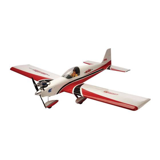
- Page 1 Instruction Manual Meridian 10cc Bedienungsanleitung Manuel d’utilisation Manuale di Istruzioni...
-
Page 2: Using The Manual
Alle Anweisungen, Garantien und anderen zugehörigen Dokumente können im eigenen Ermessen von Horizon Horizon Hobby, Inc. For up-to-date product literature, visit horizonhobby. com and click on the support tab for Hobby, Inc. jederzeit geändert werden. Die aktuelle Produktliteratur finden Sie auf horizonhobby.com unter der this product. -
Page 3: Utilisation Du Manuel
Tutte le istruzioni, le garanzie e gli altri documenti pertinenti sono soggetti a cambiamenti a totale discrezione d’Horizon Hobby, Inc. Pour obtenir la documentation à jour, rendez-vous sur le site horizonhobby.com et cliquez di Horizon Hobby, Inc. Per una documentazione aggiornata sul prodotto, visitare il sito www.horizonhobby.com sur l’onglet de support de ce produit. -
Page 4: Safety Warnings And Precautions
è opportuno far riferimento appropriate Horizon Hobby office. Komponenten. Sollten Fragen zur Kompatibilität auftreten, à ce manuel ou contactez le service technique Horizon Hobby. alle istruzioni relative al prodotto o ai componenti oppure lesen Sie bitte die Produkt- oder Bedienungsanweisung oder rivolgersi al reparto Horizon Hobby di competenza. -
Page 5: Safe Operating Recommendations
safe operating reCoMMendations eMpfehlUngen ZUM siCheren Consignes de séCUrité ConCernant raCCoMandaZioni per operare in betrieb l’Utilisation siCUreZZa • Inspect your model before every flight to ensure it is airworthy. • Überprüfen Sie zur Flugtauglichkeit ihr Modell vor jedem • Inspectez votre modèle avant chaque vol. • Controllare attentamente il modello prima di ogni volo per Flug. - Page 6 speCifiCations/speZifikationen/ large parts layoUt/baUteile (ohne kleinteile)/ spéCifiCations/speCifiChe grandes pièCes/sCheMa dei CoMponenti grandi 69.0 in (175cm) 880 sq in (56.5 dm 55.5 in (140cm) 7.00–8.00 lb (3.20–3.70 kg) 2-Stroke Gas/2-Takt Benziner/ 2 temps Essence/2-Tempi Gas 10cc 2-Stroke Glow/2-Takt Glühzünder/ 2 temps méthanol/2-Tempi Glow .52–.61 4-Stroke Glow/4-Takt Glühzünder/ 4 temps méthanol/4-Tempi Glow...
- Page 7 replaCeMent parts/ersatZteile/pièCes de reChange/riCaMbi part english deutsch français italiano HAN501501 Fuselage Rumpf Fuselage Fusoliera HAN501502 Left Wing Panel Tragfläche links Aile gauche Semiala sinistra HAN501503 Right Wing Panel Tragfläche rechts Aile droite Semiala destra HAN501504 Tail Set Heck Empennages Set coda HAN501505 Canopy Hatch Kabinenhaube...
- Page 8 asseMbly syMbol gUide/Montage syMbole /gUide des syMboles poUr asseMblage /gUida ai siMboli di asseMblaggio Apply threadlock Ensure free rotation Use medium CA Use a pencil Schraubensicherungslack verwenden Rotation sicherstellen Mittelflüssigen Verwenden Sie einen Bleistift Sekundenkleber verwenden Utilisez du frein filet Permettez une rotation libre Utilisez un crayon à...
- Page 9 reqUired radio eqUipMent/erforderliChe rC aUsrÜstUng/eqUipeMent radio reqUis/appareCChiatUre radio part # english deutsch français italiano SPMAR7010 AR7010 7-Channel DSMX Receiver AR7010 7-Kanal DSMX® Receiver Récepteur 7 voies DSMX® AR7010 Ricevitore AR7010 DSMX® a 7 canali ® JRPA004 Chargeswitch Ladestecker Interrupteur de charge JR JR Interruttore per carica ®...
- Page 10 reqUired tools/benötigtes werkZeUg/oUtils reqUis/attreZZi neCessari english deutsch français italiano Adjustable wrench Verstellbarer Schraubenschlüssel Clé ajustable Chiave regolabile C-clamp Schraubzwinge Serre joint Morsetto a C Drill bit: 1/16-inch, 5/64-inch, 3/32-inch, 9/64-inch, Bohrer: 1,5mm, 2mm, 2,5mm, 3,5mm, 4mm, 4,5mm Forêt: 1,5mm, 2mm, 2,5mm, 3,5mm, 4mm, 4,5mm Punte per trapano: 1,5mm, 2mm, 2,5mm, 3,5mm, 4mm, 5/32-inch, 11/64-inch 4,5mm...
-
Page 11: Before Starting Assembly
reqUired adhesives/erforderliChe klebstoffe/types de Colles/adesivi neCessari PAAPT03 Medium CA Sekundenkleber mittel Colle cyano moyenne Medio CA PAAPT09 Thin CA Sekundenkleber dünnflüssig Colle cyano fine Sottile CA PAAPT42 Threadlock Schraubensicherungslack Frein-filet Frenafiletti PAAPT35 15-Minute Epoxy 15 Minuten Epoxy Époxy 15 minutes Colla epoxy 15 minuti PAAPT39 30-Minute Epoxy... - Page 12 aileron and flap hinging/Montage der klappen Und qUerrUder/pose des Charnières de l’aileron et dU volet/Cerniere flap e alettoni 1 2 3 4 Remove the flaps and ailerons from the wing panel. Place a Use a pin vise and 1/16-inch (1.5mm) drill bit to drill a hole Slide the hinges into position with the T-pin resting against Place the flap and aileron back into position.
- Page 13 5 aileron and flap servo installation/einbaU des qUerrUder- Und des klappenservos/ installation des servos d’aileron et de volet/installaZione dell’alettone e del servo del flap 1 2 3 M1.5 x 10 Apply thin CA to the top and bottom of each hinge. Once the CA cures, gently pull on the fixed surface and control surface to make sure the hinges are glued securely.
- Page 14 4 5 6 7 Position the servo so it is not in contact with the cover. The Use a pin vise and 5/64-inch (2mm) drill bit to drill the holes Thread a servo mounting screw into each of the holes in the Apply a small amount of thin CA to harden the threads made output will be centered in the slot in the cover.
- Page 15 8 9 10 12 Secure the servo to the cover using the screws provided with Center the servo using the radio system. Place the servo horn Prepare both aileron servos at this time. Tie the string located inside the wing to the end of the 9-inch the servo.
- Page 16 13 14 15 17 M1.5 x 10 M1.5 x 10 Move the flap servo cover. Use the string to pull the aileron Secure the servo cover to the wing using four M1.5 x 10 self- Prepare the flap servo by following steps 3 through 8. Pull the leads for the aileron and flap servos through the lead to the opening for the flap servo.
- Page 17 18 19 20 21 M1.5 x 10 M1.5 x 10 Use a pin vise and 1/16-inch (1.5mm) drill bit to drill the Thread an M1.5 x 10 self-tapping screw into each hole to cut Apply a small amount of thin CA to harden the threads made Secure the control horn to the control surface.
- Page 18 22 wing installation/Montage der tragfläChen/installation de l’aile/Montaggio dell’ala 1 2 4 M1.5 x 10 Slide the canopy hatch forward then up to release, then aft to Slide the wing panel into position, guiding the extensions from Secure the control horn to the control surface.
- Page 19 hinging the elevators/einhängen der höhenrUder/Montage des goUvernes de profondeUr/inCernieraMento degli elevatori 1 2 3 Separate the elevators, hinges, stabilizer and joiner wire. Insert the joiner wire into the elevators. Remove any excess epoxy using a paper towel and isopropyl alcohol. With the joiner Use sandpaper to scuff the surface of the joiner wire where it wire fully inserted in the elevators, lay them flat on the work surface after putting down a piece of plastic so the elevators don’t contacts the elevators.
- Page 20 4 5 7 8 Use a pin vise and 1/16-inch (1.5mm) drill bit to drill a hole Slide the hinges into position in preparation for joining the in the center of each hinge slot to allow the CA to wick into elevators to the stabilizer.
- Page 21 stabiliZer installation/einbaU des höhenleitwerks/installation dU stabilisateUr/installaZione dello stabiliZZatore 1 3 4 5 Slide the stabilizer into the slot in the fuselage. Center the Measure from the tip of the stabilizer to the wing. Position the stabilizer. stabilizer so both measurements are equal.
- Page 22 6 7 fin and rUdder installation/einbaU der seitenflosse Und des seitenrUders/ installation de la dérive et de la goUverne de direCtion/ installaZione della deriva e del tiMone 1 2 Slide the elevator into position. Check the alignment while the epoxy cures.
- Page 23 3 4 5 6 Slide the fin into position. Remove any excess epoxy using a paper towel and rubbing alcohol. Use low-tack tape to hold the fin in position until the epoxy fully cures. Trace the outline of the fuselage on both sides of the fin. Remove the fin from the fuselage.
- Page 24 7 8 9 11 Use a pin vise and 1/16-inch (1.5mm) drill bit to drill a hole in the center of each hinge slot to allow the CA to wick into the hinge. Drill holes in both the fixed and control surfaces at Remove the tape used in the previous step.
- Page 25 fUselage servo installation/einbaU des rUMpfservos/installation des servos dU fUselage/installaZione del servo della fUsoliera 1 2 3 4 Thread a servo mounting screw into each hole to cut threads Install the grommets and brass eyelets in the servos. Secure Slide the elevator pushrod into the pushrod tube.
- Page 26 5 6 7 8 Use a pin vise and 5/32-inch (2mm) drill bit to drill the holes for the control horn mounting screws. The location has been marked in the control surface using pin holes. Slide a retainer on a clevis. Thread the nut and clevis on the pushrod.
- Page 27 9 switCh and reCeiver installation/einbaU des sChalters Und des eMpfängers/ installation de l’interrUpteUr et dU reCepteUr/installaZione dell’interrUttore e del riCevitore 1 2 3 Install the throttle servo in the fuselage. Prepare the holes for the servo mounting screws before installing the servo. Bauen Sie das Drosselservo in den Rumpf ein.
- Page 28 5 landing gear installation/Montage des fahrwerk/ installation dU train d’atterrissage/installaZione del Carrello di atterraggio 1 2 3 Secure the remote receiver inside the fuselage using hook and loop tape. M4 x 20 Befestigen Sie den Satellitenempfänger mit Klettband im Rumpf.
- Page 29 4 5 6 Slide the wheel on the axle, then secure it using the wheel Fit the axle to the main landing gear. Note the location of the Slide the wheel pant into position. Note the washer is inside collar removed in Step 1.
- Page 30 nose gear installation/einbaU des bUgfahrwerks/installation de la roUlette de neZ/installaZione del Carrello di prUa 1 3 4 5 M3 x 10 Use a flat file to create a flat area to tighten the setscrew in the wheel collar onto. Drill two holes for the mounting strap using a 5/32-inch Center the wheel in the wheel pant.
- Page 31 6 7 8 Slide the 1.8 x 400mm steering pushrod into the pushrod tube from inside the fuselage. Attach the Z-bend in the pushrod to the rudder servo horn. You will need to remove the horn to Slide a clevis retainer on a metal clevis.
- Page 32 gas engine installation/benZin Motor einbaU/ installation dU MoteUr a essenCe/installaZione di Un Motore a sCoppio 1 2 3 4 M4 x 30 Position the engine so the distance from the face of the drive Use a drill and 5/32-inch (4mm) drill bit to drill the holes for washer to the firewall measures 136mm.
- Page 33 5 6 7 8 Use a drill and 3/32-inch (2.5mm) drill bit to drill a hole in the firewall for the throttle pushrod tube. Slide the throttle pushrod tube into the fuselage. With the Secure the connector to the servo arm in the location shown. Bohren Sie mit einem 2,5-mm-Bohrer ein Loch für das tube positioned so equal amounts protrude from the firewall Drossel-Gestängerohr in den Motorspant.
- Page 34 9 10 11 12 With the radio system on, center the throttle stick and trim. Attach the throttle servo arm to the throttle servo so it is perpendicular to the servo centerline. Slide the pushrod Apply a drop of thin CA on the nut to prevent it from vibrating through the tube, then through the fitting on the throttle servo loose.
- Page 35 13 14 15 16 Secure the ignition module in the fuselage using hook and Pass the lead for the ignition through the rectangular hole loop tape. Route the wires as necessary, making sure to in the firewall. Connect to the corresponding lead from the connect the lead from the ignition switch and the sensor from ignition module.
- Page 36 17 18 fUel tank installation/einbaU des kraftstofftanks/ installation dU reservoir de CarbUrant/installaZione del serbatoio 1 2 Secure the ignition battery in the fuselage using hook and Secure the receiver battery in the fuselage using hook and loop tape.
- Page 37 3 4 ep Motor installation/ e-Motor einbaU/ installation dU MoteUr ep/installaZione del Motore elettriCo 1 2 Secure three 140mm pieces of fuel tubing to the tubes of Slide the fuel tank in the fuselage, guiding the tubes through the stopper.
- Page 38 3 4 Cowling and spinner installation/anbringen der verkleidUng Und des spinners/installation dU Capot MoteUr et dU Cone d’heliCe/ installaZione della CarenatUra e dell’ogiva 1 2 Secure the battery tray in the fuselage. Place a piece of hook Place a mating piece of hook and loop tape on the battery.
- Page 39 3 4 5 6 M3 x 10 M3 x 10 Use low-tack tape to hold the cowling in position while drilling the holes for the cowl mounting screws using a drill and a 3/32-inch (2.5mm) drill bit. Thread an M3 x 10 screw into each hole to cut threads in the Apply a small amount of thin CA to harden the threads made Slide the cowl back into position.
- Page 40 7 8 M3 x 10 Secure the muffler to the engine using the muffler extension and the screws provided with the extension. Secure the spinner using the screws and a #1 Phillips Befestigen Sie den Schalldämpfer mit der screwdriver.
-
Page 41: Center Of Gravity
Center of gravity der sChwerpUnkt Centre de gravité Centro di gravita’ (bariCentro) An important part of preparing the aircraft for flight is Ein sehr wichtiger Teil in der Flugvorbereitung ist es das Une des étapes importantes de la préparation d’un modèle Un punto importante per preparare l’aereo al volo è... -
Page 42: Control Throws
Control throws rUderaUssChläge 1. Turn on the transmitter and receiver of your model. Check the movement of the rudder using the transmitter. When the stick 1. Schalten Sie den Sender und Empfänger ihres Modells ein. Prüfen Sie die Seitenruderaussschläge mit dem Sender. is moved to the right, the rudder should also move right. -
Page 43: Corse Dei Comandi
débatteMents Corse dei CoMandi 1. Mettez l’émetteur et le récepteur sous tension. Contrôlez les mouvements de la dérive en utilisant votre émetteur. Quand le 1. Accendere trasmettitore e ricevitore del modello. Controllare i movimenti del timone agendo sul trasmettitore. Quando manche est vers la droite, la dérive doit s’orienter vers la droite. -
Page 44: Preflight Checklist
preflight CheCklist vorflUgkontrolle CheCklist d’avant vol lista dei Controlli priMa del volo • C harge the transmitter, receiver and motor battery for • L aden Sie den Sender- ,Empfänger- und Zündakku für • C hargez la batterie de votre émetteur, de réception • C aricare le batterie di trasmettitore, ricevitore e your airplane. Use the recommended charger supplied Ihr Flugzeug. Verwenden Sie für die RC Anlage bitte et d’allumage. -
Page 45: Daily Flight Checks
daily flight CheCks tägliCher flUg CheCk Contrôles systéMatiqUes Controlli di volo giornalieri • C heck the battery voltage of the transmitter battery. Do • Ü berprüfen Sie die Spannung des Senderakkus. Fliegen • C ontrôlez la tension de la batterie de l’émetteur. Ne volez • C ontrollare la tensione della batteria del trasmettitore. not fly below the manufacturer’s recommended voltage. Sie nicht wenn die Spannung unterhalb der vom jamais en dessous de la tension minimale recommandée Non volare se la tensione è... -
Page 46: Limitation Of Liability
By the act at our facility. An Online Service Request is available MasterCard, American Express, and Discover cards. By service by anyone other than a Horizon Hobby authorized of use, setup or assembly, the user accepts all resulting athttp://www.horizonhobby.com/content/_ service-center_... -
Page 47: Sicherheitshinweise
Sollten wir nach 90 Tagen keineEinverständniserklärung zur aus. Rücksendungen durch den Käufer direkt an Horizon oder Exklusive Garantie ¬ Horizon Hobby Inc (Horizon) Muss Ihr Produkt gewartet oder repariert werden, wenden Sie Reparatur vorliegen haben, behalten wir uns vor, das Produkt eine seiner Landesvertretung bedürfen der Schriftform. -
Page 48: Garantie Et Réparations
électroniques et les moteurs. les Garantie exclusive - Horizon Hobby, Inc. (Horizon) garantit Votre revendeur spécialisé local et le point de vente ne fonctionnement ainsi que des tentatives d’entretien ou de réparations touchant à... - Page 49 Manutenzione e riparazione Garanzia esclusiva - Horizon Hobby, Inc., (Horizon) Horizon non si riterrà responsabile per danni speciali, Se il prodotto deve essere ispezionato o riparato, si prega di garantisce che i prodotti acquistati (il “Prodotto”) sono diretti, indiretti o consequenziali;...
- Page 50 25337 Elmshorn, Germany service@horizonhobby.de Room 506, No. 97 Changshou Rd. +86 (021) 5180 9868 11 Rue Georges Charpak +33 (0) 1 60 18 34 90 China Horizon Hobby – China France Horizon Hobby SAS Shanghai, China 200060 info@horizonhobby.com.cn 77127 Lieusaint, France infofrance@horizonhobby.com Room 506, No.
-
Page 51: Ama National Model Aircraft Safety Code
aMa national Model airCraft safety Code effective January 1, 2011 b. radio Control (rC) (h) Not operate model aircraft while under the influence of 7. Under no circumstances may a pilot or other person touch alcohol or while using any drug which could adversely affect a model aircraft in flight while it is still under power, except a. - Page 52 © 2012 Horizon Hobby, Inc. Hangar 9, DSMX, JR, Evolution, EC3 and Celectra are trademarks or registered trademarks of Horizon Hobby, Inc. The Spektrum trademark is used with permission of Bachmann Industries, Inc. All other trademarks, service marks and logos are the property of their respective owners.