
Manuels Connexes pour Horizon Hobby HANGAR 9 Model 12 Viking 120cc


Sommaire des Matières pour Horizon Hobby HANGAR 9 Model 12 Viking 120cc
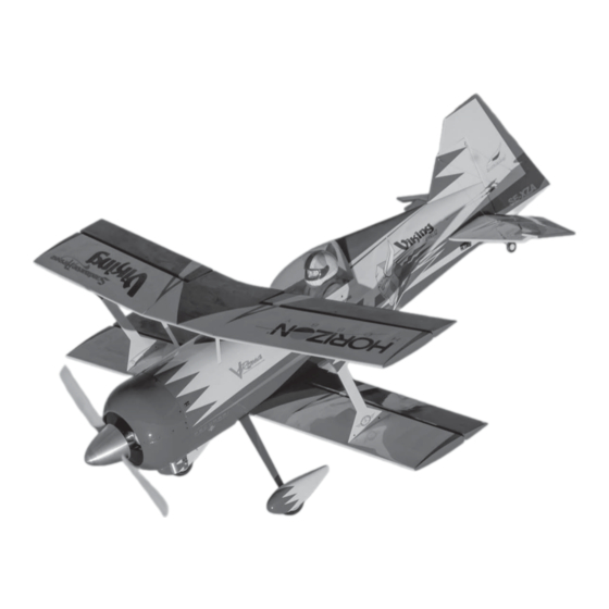
- Page 1 ® Model 12 Viking 120cc Instruction Manual Bedienungsanleitung Manuel d’utilisation Manuale di Istruzioni...
- Page 2 SPECIFICATIONS • SPEZIFIKATIONEN • SPÉCIFICATIONS • SPECIFICHE 2-Stroke Gas • 2-Takt Benziner Spinner • Spinner • Cône • Ogiva dell’elica: 89.2 in (2.26 m) 2 temps Essence • 2-Tempi Gas: 6-inch (152mm) 100cc–125cc (not included • nicht im Lieferumfang enthalten 2003 sq in (129 dm2) Total/Totale •...
- Page 3 Part # English Deutsch Français Italiano RECEIVER (RECOMMENDED) • EMPFÄNGER (EMPFOHLEN) • RÉCEPTEUR (RECOMMANDÉ) • RICEVENTE (CONSIGLIATO) ™ ® AR9110 9-Channel DSMX PowerSafe Spektrum AR9110 9-Kanal DSMX-PowerSafe- SPMAR9110 Récepteur DSMX PowerSafe 9 voies AR9110 Ricevente AR9110 9-canali DSMX® PowerSafe Receiver Empfänger SPMB4000LP (2) LiPo Receiver Pack 4000mAh...
- Page 4 Part # English Deutsch Français Italiano REQUIRED ADHESIVES • ERFORDERLICHE KLEBSTOFFE • TYPES DE COLLES • ADESIVI NECESSARI PAAPT09 Thin CA Sekundenkleber dünnfl üssig Colle cyano fi ne Sottile CA PAAPT03 Medium CA Sekundenkleber mittel Colle cyano moyenne Medio CA PAAPT715 CA Accelerator Sekundenkleber (CA) Aktivator...
-
Page 5: Before Starting Assembly
Horizon Hobby, LLC. This manual contains instructions for safety, operation and maintenance. It is essential to read and follow all the instructions and warnings in the manual, prior to assembly, setup or use, in order to operate •... -
Page 6: Empfehlungen Zum Sicheren Betrieb
Halten Sie lose Gegenstände die sich im Propeller verfangen können weg vom Propeller. Dieses gilt auch für Kleidung Alle Anweisungen, Garantien und anderen zugehörigen Dokumente können im eigenen Ermessen von Horizon Hobby, oder andere Objekte wie zum Beispiel Stifte oder Schraubendreher. -
Page 7: Avant De Commencer L'assemblage
être utilisé par des enfants sans la surveillance directe d’un adulte. N’essayez pas de modifi er ou d’utiliser ce produit avec des composants incompatibles hors des instructions fournies par Horizon Hobby, LLC. Ce manuel comporte des Si l’entoilage présente quelque plis, vous pouvez les lisser en utilisant le pistolet à air chaud (HAN100) et le gant instructions relatives à... - Page 8 • Se si trovano parti danneggiate, contattare il negozio da cui è stato acquistato. o alterare il prodotto in nessuna maniera al di fuori delle istruzioni fornite da Horizon Hobby, LLC. Questo manuale contiene le istruzioni per un funzionamento e una manutenzione sicuri. È fondamentale leggere e seguire tutte le Se si trovano delle pieghe nella ricopertura, si possono togliere usando una pistola ad aria calda (HAN100) e guanto per istruzioni e le avvertenze del manuale prima di montare, confi...
- Page 9 BUILDING PRECAUTIONS HINWEISE ZUM BAU PRÉCAUTIONS D’ASSEMBLAGE PRECAUZIONI PER LA COSTRUZIONE During assembly, we recommend resting the parts on a Während des Zusammenbaus empfehlen wird, dass die Lors de l’assemblage de votre modèle, nous vous Durante l’assemblaggio noi consigliamo di appoggiare soft surface such as a soft towel to help prevent denting Teile auf einer weichen Oberfl...
- Page 10 AILERON SERVO INSTALLATION Secure a 9-inch (230mm) extension to the servo lead for the top wing aileron servos using a servo connector Apply a small mount of 5-minute epoxy to an 8-32 x 1 clip. The servos for the bottom wing aileron servos will inch countersunk screw.
- Page 11 11. Tie the string located in the wing around the end of the 16. Thread the 1 -inch (38mm) turnbuckle 10 turns into the aileron servo extension. Use the string to pull the servo ball end on the control horn. There will be equal amounts lead through the wing.
- Page 12 Lift the canopy at the rear, then slide it back slightly to Remove any debris from the covers using a paper towel remove it from the fuselage. Set the canopy aside in a and isopropyl alcohol. safe location. Check the threads for the cabane struts using a 4-40 x Use a hobby knife with a #11 blade to cut a an opening 3/8-inch socket head cap screw.
- Page 13 12. Use a 6-32 tap to clear the threads if the screws do not 17. Use canopy glue to glue the front cabane strut cover in thread in easily. position. 13. Attach the top wing center section to the cabane struts BOTTOM WING INSTALLATION using four 6-32 x 1/2-inch socket head cap screws.
- Page 14 TOP WING INSTALLATION Slide the stabilizer into the slot in the fuselage. Measure from the fuselage to each stabilizer tip and adjust so both Install the wing tube in the top wing, then slide the tube measurements are equal. Measure from each wing tip into the top wing center section.
- Page 15 Slide the stabilizer into position and check its alignment ELEVATOR SERVO INSTALLATION to the wings and fuselage. Remove any excess epoxy Prepare the elevator servo and install it in the fuselage using a paper towel and isopropyl alcohol. Allow the following the same procedure as the aileron servos.
- Page 16 Thread the 3-inch (76mm) turnbuckle 10 turns into the Brush a layer of 30-minute epoxy on the exposed wood ball end on the servo arm. of the fi n. Make sure to apply epoxy to both sides of the fi n. Thread the 3-inch (76mm) turnbuckle 10 turns into the Brush a layer of 30-minute epoxy into the slot in the ball end on the control horn.
- Page 17 Thread the cable ends into the ball link on the control RUDDER SERVO INSTALLATION horn 10 turns. Prepare both control horns at this time. Mount the rudder servo in the radio tray with the output of the servo facing the rear of the fuselage. The holes for mounting the servo will need to be prepared following the same procedure as the aileron servo mounting holes.
-
Page 18: Receiver And Receiver Battery Installation
Attach the ball links to the rudder servo arm so they are Remove the hatches from the bottom of the fuselage -inch (32mm) from the center of the control horn. using a 1/16-inch hex wrench. Set the hatch covers Make sure the tapered washer is between the ball link aside. - Page 19 A further remote receiver is placed between the fi rst two Slide a #4 washer and a three-hole brass cable fi tting receivers, as low in the fuselage as possible. The feeder on each of the 4-40 x 3/4-inch socket head cap screws. antenna for this receiver are oriented toward the top and Attach the tail wheel bracket to the fuselage using the bottom of the fuselage.
- Page 20 Fit the Z-bend into the tiller arm. Attach the ball link Slide a clevis retainer over the end of the metal clevis. to the tail wheel steering arm. Adjust the length of the Thread a 2-56 nut on the threaded cable fi tting, then linkage as necessary to correct any tracking problems thread the fi...
- Page 21 10. Attach the cables to the brass three-hole fi ttings at the Secure the wheel using a 5/32-inch wheel collar, tail wheel bracket. tightening the setscrew on the outer fl at area. Make sure to use thread lock on the setscrew to prevent it from vibrating loose.
- Page 22 Soak the wooden spacers for the engine with thin CA to Secure the ignition battery to the radio tray using hook prevent fuel from soaking into the spacers. Allow the CA and loop tape and a hoop and loop strap. to fully cure before proceeding.
- Page 23 12. Use the manual included with the engine for the linkage Locate the bottom cowl. It can be identifi ed by the blind position at the servo. A quick connector (not included) nuts along the edge where the upper cowl will overlap will be required to attach the linkage to the servo arm.
- Page 24 Once the lower cowl has been trimmed to fi t the muffl ers, the upper and lower cowl can be joined using eight 4-40 x 1/4-inch button head screws and eight #4 washers. Tighten the screws using a 1/16-inch hex wrench.
-
Page 25: Center Of Gravity
CENTER OF GRAVITY CONTROL THROWS An important part of preparing the aircraft for fl ight is properly balancing the model. Turn on the transmitter and receiver of your model. Check the movement of the rudder using the transmitter. When the stick is moved to the right, the rudder should also move right. Reverse the direction of the servo at the Attach the wing panels to the fuselage. -
Page 26: Preflight Checklist
INCIDENTAL OR CONSEQUENTIAL DAMAGES, LOSS OF your airplane. Use the recommended charger supplied Do not fl y below the manufacturer’s recommended Horizon Hobby, LLC, (Horizon) warrants to the original PROFITS OR PRODUCTION OR COMMERCIAL LOSS IN ANY with your radio system. Follow the instructions voltage. -
Page 27: Warranty And Service Contact Information
Germany 25337 Elmshorn, When calling Horizon, you will be asked to provide your return freight. Horizon accepts money orders and Sales: Horizon Hobby GmbH +49 (0) 4121 2655 100 Germany complete name, street address, email address and phone cashier’s checks, as well as Visa, MasterCard, American number where you can be reached during business Express, and Discover cards. - Page 28 MONTAGE DES SERVOS DES QUERRUDERS Eine 230 mm (9 Zoll) Verlängerung an der Servoleitung der Servos für das Querruder des oberen Flügels Eine kleine Menge des 5-minütigen Epoxids auf eine mit einer Servosteckerklemme sichern. Die Servos für 8-32 x 32 mm (1 Zoll) Senkkopfschraube auftragen.
-
Page 29: Montage Des Mittelteils Des Oberen Flügels
11. Die im Flügel befi ndliche Schnur um das Ende der 16. Die 38 mm (1 Zoll) Spannschraube 10 Umdrehungen in Servoverlängerung des Querruders binden. Mit der das Gelenkkopfende auf dem Steuerhorn schrauben. Es Schnur die Servoleitung durch die Flügelwurzel ziehen. gibt in jedem Kugelende an diesem Zeitpunkt die gleiche Anzahl an Gewindegängen. - Page 30 Die Kanzel am hinteren Teil anheben, dann leicht Mit einem Papiertuch und Isopropylalkohol sämtliche zurückschieben, um es vom Rumpf zu entfernen. Die Schmutzrückstände von den Abdeckungen entfernen. Kanzel an einem sicheren Ort ablegen. Die Gewinde der Baldachinstreben mit einer 4-40 Mit einem Hobbymesser mit einer Nr. 11 Klinge eine x 9 mm (3/8 Zoll) Zylinderkopfschraube prüfen.
- Page 31 12. Einen 6-32 Gewindezapfen zum Säubern der Gewinde 17. Mit dem Kanzelkleber die vordere Baldachinabdeckung verwenden, wenn sich die Schrauben nicht leicht in Position kleben. schrauben lassen. 13. Das Mittelteil des oberen Flügel mit vier 6-32 x MONTAGE DES UNTEREN FLÜGELS 12,7 mm (1/2 Zoll) Zylinderkopfschrauben an den Das Steckungsrohr in die untere Tragfl...
- Page 32 MONTAGE DES OBEREN FLÜGELS Den Stabilisator in den Schlitz am Rumpf schieben. Vom Rumpf bis zu jeder Stabilisatorspitze messen und Das Steckungsrohr im oberen Flügel montieren, dann anpassen, sodass beide Messwerte gleich sind. Von jeder das Rohr in den Mittelteil des oberen Flügels schieben. Flügelspitze bis zu jeder Stabilisatorspitze messen und Die Servoleitung anschließen, dann die Tragfl...
-
Page 33: Montage Des Servors Des Höhenruders
Den Stabilisator in Position schieben und seine MONTAGE DES SERVORS DES Ausrichtung zu den Flügeln und zum Rumpf prüfen. HÖHENRUDERS Mit einem Papiertuch und Isopropylalkohol sämtliche Epoxidrückstände entfernen. Das Epoxid muss vor dem Den Servo des Höhenruders vorbereiten und ihn im Fortfahren vollständig ausgehärtet sein. - Page 34 Die 76 mm (3 Zoll) Spannschraube 10 Umdrehungen in Eine Schicht 30-minütigen Epoxid auf das freiliegende das Gelenkkopfende auf dem Servoarm schrauben. Holz des Seitenleitwerks auftragen. Sicherstellen, Epoxid auf beiden Seiten des Seitenleitwerks aufzutragen. Die 76 mm (3 Zoll) Spannschraube 10 Umdrehungen in Eine Schicht 30-minütigen Epoxid in den Schlitz im das Gelenkkopfende auf dem Steuerhorn schrauben.
-
Page 35: Montage Des Servors Des Seitenruders
Die Drahtenden in den Gelenkkopf auf dem Steuerhorn MONTAGE DES SERVORS DES mit 10 Umdrehungen schrauben. Beide Steuerhörner SEITENRUDERS zum jetzigen Zeitpunkt vorbereiten. Den Servo des Seitenruders in der Funkhalterung befestigen, wobei der Servoausgang auf das Heck des Rumpfs weist. Die Löcher für die Servohalterung müssen entsprechend den Schritten für die Löcher der Servohalterung des Querruders vorbereitet werden. -
Page 36: Montage Von Empfänger Und Empfänger-Akku
Die Gelenkköpfe so am Servoarm des Seitenruders Die Abdeckungen von der Unterseite des Rumpfs mit anbringen, dass sie sich 32 mm (1 Zoll) von der einem 1,6 mm (1/16 Zoll) Sechskant entfernen. Die Mitte des Steuerhorns befi nden. Sicherstellen, dass die Abdeckungen zur Seite legen. konische Unterlegscheibe zwischen Gelenkkopf und Servoarm liegt. - Page 37 Ein weiterer Funkempfänger wird zwischen die beiden Eine Nr. 4 Unterlegscheibe und ein Messing-Drahtfi tting ersten Empfänger so weit unten wie möglich im Rumpf mit drei Öffnungen auf jede der 4-40 x 19 mm (3/4 Zoll) platziert. Die Zuleitungsantenne dieses Empfängers wird Zylinderkopfschrauben schieben.
- Page 38 Die Z-Krümmung in den Pinnenarm einpassen. Den Einen Gabelkopfhalter über das Ende des Gabelkopfs aus Gelenkkopf am Steuerarm des Spornrads befestigen. Metall schieben. Eine 2-56 Mutter auf das Gewinde des Die Länge des Gestänges entsprechend anpassen, um Drahtfi tting schrauben, dann das Fitting in den Gabelkopf Ortungsprobleme während des Rollens zu korrigieren.
- Page 39 10. Die Drähte am Messing-Fitting mit drei Öffnungen an der Das Rad mit einer 4 mm (5/32 Zoll) Anschlaghülse Halterung des Spornrads befestigen. sichern und die Feststellschraube auf dem äußeren fl achen Bereich festziehen. Sicherstellen, Gewindesicherung auf der Feststellschraube zu verwenden, um ein Lösen unter Vibrationen zu verhindern.
- Page 40 Die hölzernen Distanzstücke für den Motor mit dünnem Den Zünd-Akku mit dem Klettband an der Funkhalterung CA-Klebstoff einweichen, um zu verhindern, dass sichern. Kraftstoff in die Distanzstücke eindringt. Der CA-Klebstoff muss vor dem Fortfahren vollständig ausgehärtet sein. Den Motor mit vier Distanzstücken und vier 1/4-20 x Den Zünd-Akku am Schalter mit einer 460 mm (18 Zoll) 38 mm (1 Zoll) Zylinderkopfschrauben am Brandschott...
- Page 41 12. Die mit dem Motor mitgelieferte Anleitung für die Die untere Motorhaube auffi nden. Sie ist anhand der Position des Gestänges auf dem Servo verwenden. Einen Blindmuttern entlang der Kante erkennbar, an der die Schnellverbinder (nicht enthalten) ist erforderlich, um obere Motorhaube übersteht und angebracht wird.
- Page 42 Sobald die untere Motorhaube getrimmt ist, sodass die Schalldämpfer passen, können die obere und untere Motorhaube mit acht 4-40 x 6,4 mm (1/4 Zoll) Rundkopfschrauben und acht Nr. 4 Unterlegscheiben verbunden werden. Die Schrauben mit einem 2,5 mm (1/16 Zoll) Sechskant festziehen. Den Propeller und die Spinnerrückplatte mit der mit dem Motor mitgelieferten Hardware am Motor befestigen.
-
Page 43: Der Schwerpunkt
DER SCHWERPUNKT RUDERAUSSCHLAG Ein wichtiger Teil in der Vorbereitung des Flugzeug ist das korrekt einrichten des Schwerpunktes. Den Sender und Empfänger des Modells einschalten. Die Bewegung des Seitenruders mit der Fernsteuerung prüfen. Wird der Steuerhebel nach rechts bewegt, sollte sich auch das Seitenruder nach rechts bewegen. Die Montieren Sie die Tragfl... -
Page 44: Garantie Und Service Informationen
• Prüfen Sie den RC Einbau und stellen sicher dass alle vernünftig gesichert sind. Exklusive Garantie Horizon Hobby LLC (Horizon) Ausgeschlossen sind auch Fälle die bedingt durch (vii) Ruderfunktionen (Quer-, Höhen-, Seitenruder) und • Stellen Sie sicher, dass sich alle Ruder in die richtige... -
Page 45: Garantie Und Service Kontaktinformationen
Sie sich entweder an Ihren Fachhändler oder direkt an das Produkt repariert oder ersetzt. Diese Entscheidung Hinweise für die Wartung und den Betrieb des Produktes. Horizon. obliegt einzig Horizon Hobby. Es ist unabdingbar, diese Hinweise vor der ersten Rücksendungen / Reparaturen werden nur mit einer Kostenpfl ichtige Reparaturen Inbetriebnahme zu lesen und zu verstehen. - Page 46 INSTALLATION DU SERVO D’AILERONS Fixez une rallonge de 230mm au câble du servo des servos des ailerons de l’aile supérieure à l’aide d’un Appliquez un peu de colle époxy 5 minutes sur une vis à clip de sécurité de rallonge servo. Pour les servos des tête plate 8-32 x 1/4’.
-
Page 47: Installation De La Partie Centrale De L'aile Supérieure
11. Attachez le fi l situé dans l’aile après l’extrémité de la 16. Vissez la tringlerie de 38mm de 10 tours dans la chape rallonge de servo ailerons. Servez-vous du fi l pour faire sur le guignol. Le fi letage sera de la même longueur sur passer le câble servo dans l’aile. - Page 48 Soulevez la verrière par l’arrière puis tirez-la légèrement Retirez débris et poussière des habillages avec du papier en arrière pour la retirer du fuselage. Mettez la verrière absorbant et de l’alcool dénaturé. de côté à un endroit sûr. Vérifi ez le fi letage pour les haubans de cabane en Utilisez un couteau de modélisme avec une lame #11 utilisant un vis BTR 4-40 x 3/8’.
- Page 49 12. Utilisez un taraud 6-32 pour nettoyer le fi letage si les vis 17. Utilisez de la colle pour verrière pour coller l’habillage sont diffi ciles à visser. avant du hauban de cabane. 13. Fixez la partie centrale de l’aile supérieure aux haubans INSTALLATION DE L’AILE INFÉRIEURE de cabane à...
-
Page 50: Installation Du Stabilisateur Et De La Profondeur
INSTALLATION DE L’AILE SUPÉRIEURE Glissez le stabilisateur dans l’encoche du fuselage. Mesurez la distance entre le fuselage et chaque Installez la clé d’aile dans l’aile supérieure puis glissez extrémité de stabilisateur et faites les ajustements la clé d’aile dans la partie centrale de l’aile supérieure. nécessaires afi... - Page 51 Mettez le stabilisateur en place et vérifi ez son alignement INSTALLATION DU SERVO DE PROFONDEUR avec les ailes et le fuselage. Retirez l’excédant de colle Préparez le servo de profondeur et installez-le dans le époxy avec du papier absorbant et de l’alcool dénaturé. fuselage en suivant les mêmes instructions que pour Laissez la colle époxy sécher avant de continuer.
- Page 52 Vissez la tringlerie de 76mm de 10 tours dans la chape Appliquez une couche de colle époxy 30 minutes sur le du palonnier de servo. bois apparent de la partie fi xe de la dérive. Assurez-vous d’appliquer de la colle époxy sur les deux côtés. Vissez la tringlerie de 76mm de 10 tours dans la chape Appliquez une couche de colle époxy 30 minutes dans du guignol.
- Page 53 Vissez l’extrémité du câble dans la chape à rotule dans INSTALLATION DU SERVO DE DÉRIVE le guignol de 10 tours. Préparez les deux guignols à ce Installez le servo de dérive sur la platine radio avec la moment-là. sortie orientée vers l’arrière du fuselage. Les trous de fi...
-
Page 54: Installation Du Récepteur Et De Sa Battrerie
Attachez les chapes à rotules au palonnier de servo de Retirez les trappes qui se situent sous le fuselage à l’aide dérive afi n qu’ils soient à 32mm du centre du guignol. d’une clé BTR 1/16’. Mettez les trappes de côté. Assurez-vous que la rondelle se situe bien entre la chape à... - Page 55 Un autre récepteur satellite est placé entre les deux Glissez une rondelle #4 et un renfort à trois trous en premiers récepteurs, au plus bas possible dans le laiton sur chaque vis BTR 4-40 x 3/4’. Fixez le support fuselage. L’antenne est orientée vers le haut et le bas du de roulette de queue sur le fuselage à...
-
Page 56: Installation Des Haubans D'empennage
Insérez la partie en Z dans la bras de levier. Attachez Glissez la fi xation de chape sur l’extrémité de la chape la chape à rotule au bras de direction de la roulette de métallique. Vissez un écrou 2-56 sur la tige fi letée puis queue. - Page 57 10. Attachez les câbles aux renforts à trois trous en laiton au Fixez la roue à l’aide d’une bague d’arrêt 5/32’, en support de roulette de queue. serrant la vis de pression sur le méplat extérieur. Assurez-vous de bien appliquer du frein-fi let sur la vis de pression pour éviter qu’elle se desserre à...
- Page 58 Recouvrez l’entretoise en bois pour moteur de colle Fixez la batterie d’allumage sur la platine radio à l’aide cyano fi ne pour éviter au carburant de s’imprégner d’une bande ou d’une sangle auto-agrippante. dans l’entretoise. Laissez la colle cyano sécher avant de continuer.
- Page 59 12. Utilisez le manuel inclus avec le moteur pour connaitre Repérez la partie inférieure du capot. Vous le la position des tringleries sur le servo. Une prise rapide reconnaîtrez avec les écrous borgne situé sur le bord sur (non fournie) sera nécessaire pour attacher la tringlerie lequel la partie supérieure du capot viendra se poser et au palonnier de servo.
- Page 60 Une fois que le capot inférieur a été découpé pour s’adapter aux silencieux, assemblez les capots inférieur et supérieur à l’aide de huit vis BTR 4-40 x 1/4’ et huit rondelles #4. Serrez les vis à l’aide d’une clé BTR 1/16’. Fixez l’hélice et la fl...
-
Page 61: Centre De Gravité
CENTRE DE GRAVITÉ DÉBATTEMENTS Une des étapes importantes de la préparation d’un modèle est son équilibrage. Mettez l’émetteur et le récepteur sous tension. Contrôlez les mouvements de la dérive en utilisant votre émetteur. Quand le manche est vers la droite, la dérive doit s’orienter vers la droite. Inversez la direction du servo à Fixez les ailes sur le fuselage. -
Page 62: Contrôles Systématiques
Utilisez le chargeur fourni avec votre Ne volez jamais en dessous de la tension minimale Garantie exclusive - Horizon Hobby, LLC (Horizon) garantit de revenus ou de pertes commerciales, liés de quelque radio. Suivez les instructions fournies avec votre recommandée par le fabricant. -
Page 63: Coordonnées De Garantie Et Réparations
Cette coûteuses et doivent par conséquent être effectuées revendeur qui conviendra avec Horizon d’une décision décision relève uniquement d’Horizon Hobby. par l’acheteur lui-même. appropriée, destinée à vous aider le plus rapidement Réparations payantes... - Page 64 INSTALLAZIONE SERVO ALETTONI Collegare una prolunga da 23cm al connettore del servo per gli alettoni dell’ala superiore, fi ssandola con una Mettere una piccola quantità di colla epoxy 5 minuti su clip. I servi per gli alettoni dell’ala inferiore usano una di una vite a testa svasata da 8-32 x 1/4”.
- Page 65 11. Legare la cordicella che si trova all’interno dell’ala al 16. Avvitare un tenditore da 38mm per 10 giri nel terminale terminale della prolunga per il servo alettoni. Usare la dell’attacco a sfera sulla squadretta dell’alettone. A cordicella per tirare il fi lo del servo attraverso l’ala. questo punto la quantità...
- Page 66 Sollevare la parte posteriore della capottina, poi farla Pulire eventuali detriti dalla copertura con un fazzoletto scorrere leggermente indietro per staccarla dalla di carta e alcol. fusoliera. Mettere da parte la capottina in un posto sicuro. Controllare le fi lettature per i montanti della cabana con Usare un coltello con lama #11 per tagliare un’apertura una vite a brugola da 4-40 x 3/8”.
- Page 67 12. Se le viti non si avvitano facilmente, usare un maschio da 17. Usare colla per capottine anche per incollare in 6-32” per pulire la fi lettatura. posizione la copertura del montante anteriore della cabana. 13. Fissare la parte centrale dell’ala superiore ai montanti INSTALLAZIONE ALA INFERIORE della cabana con 4 viti a brugola da 6-32 x 1/2”.
- Page 68 INSTALLAZIONE ALA SUPERIORE Inserire lo stabilizzatore nella sua sede sulla fusoliera. Misurare dalla fusoliera in modo che lo stabilizzatore sia Inserire il tubo prima nella semiala superiore e poi nella perfettamente al centro. Misurare anche le estremità sezione centrale. Collegare il fi lo del servo e poi far dello stabilizzatore rispetto alle estremità...
- Page 69 Inserire completamente lo stabilizzatore e controllare INSTALLAZIONE DEL SERVO ELEVATORE il suo allineamento con ala e fusoliera. Togliere gli Preparare il servo per l’elevatore e installarlo nella eccessi di colla con un fazzoletto di carta e alcol. fusoliera seguendo la stessa procedura utilizzata per Prima di procedere attendere che la colla si asciughi i servi degli alettoni.
- Page 70 Avvitare un tenditore da 76mm per 10 giri nel terminale Spalmare uno strato di colla epoxy 30 minuti sul legno dell’attacco a sfera sul braccio del servo. esposto su entrambi i lati della deriva. Avvitare un tenditore da 76mm per 10 giri nel terminale Spalmare uno strato di colla epoxy 30 minuti nella sede dell’attacco a sfera sulla squadretta dell’elevatore.
- Page 71 Avvitare per 10 giri i terminali del cavo nell’attacco INSTALLAZIONE DEL SERVO TIMONE a sfera sulla squadretta. A questo punto preparare Montare il servo del timone sulla piastra portaradio con entrambe le squadrette. l’albero di uscita rivolto verso la parte posteriore della fusoliera.
- Page 72 Fissare gli attacchi a sfera ai bracci del servo del timone Con una chiavetta esagonale da 1/16” togliere i portelli in modo che si trovino a 32mm dal centro. Accertarsi che sotto alla fusoliera e metterli da parte. la rondella conica si trovi tra l’attacco a sfera e il braccio del servo.
- Page 73 Una ulteriore ricevente remota si può piazzare tra le Inserire una rondella #4 e un raccordo in ottone a tre prime due il più in basso possibile nella fusoliera. fori per cavo, su ciascuna vite a brugola da 4-40 x 3/4”. Fissare il supporto del ruotino di coda alla fusoliera con due viti a brugola usando una chiave adatta.
- Page 74 Inserire la piegatura a Z nella squadretta del timone. Inserire sulla forcella un anello di bloccaggio, avvitare Fissare l’attacco a sfera sul braccio di comando del un dado da 2-56” sul raccordo del cavo e poi avvitare la ruotino di coda. Regolare le lunghezza dell’asta di forcella fi...
- Page 75 10. Fissare i cavi al raccordo in ottone a 3 fori sul supporto Fissare la ruota con un collare da 5/32” stringendo il del ruotino di coda. grano sull’area piatta esterna. Bisogna applicare del frenafi letti sul grano per evitare che si allenti a causa delle vibrazioni.
- Page 76 Bagnare i distanziali in legno del motore con colla CA Fissare la batteria dell’accensione al supporto radio con liquida per evitare che si impregnino di carburante. nastro e fascette a strappo. Prima di procedere attendere che la colla CA sia completamente asciutta.
- Page 77 12. Per regolare la posizione dell’asta di rinvio sul motore Individuare la parte inferiore della capottina motore. Si e sul servo bisogna seguire il manuale del motore. Un può identifi care per la presenza dei dadi ciechi lungo il connettore rapido (non fornito) è necessario per fi ssare bordo dove quella superiore si sovrappone e si collega.
- Page 78 Una volta che la capottina inferiore è stata ritagliata per adattarla al silenziatore, le due semi capottine si possono unire usando otto viti a testa tonda da 4-40 x 1/4” e otto rondelle #4. Stringere le viti con chiavetta esagonale da 1/16”.
-
Page 79: Baricentro (Cg)
BARICENTRO (CG) CORSE DEI COMANDI Una parte molto importante nella preparazione del modello per il volo, è il suo bilanciamento. Accendere trasmittente e ricevente del modello. Verifi care il movimento del timone agendo sulla trasmittente. Quando si sposta lo stick verso destra il timone deve andare a destra. Se necessario invertire la direzione del Fissare l’ala alla fusoliera. -
Page 80: Lista Dei Controlli Prima Del Volo
Non volare se la tensione è inferiore a quella indicata Garanzia esclusiva - Horizon Hobby, LLC (Horizon) non idonei a cura di soggetti diversi da Horizon. La consigliati o forniti con il radiocomando e seguendo dal costruttore;... -
Page 81: Contatti Per La Garanzia E L'assistenza
Horizon per prendere una decisione che vi Questa decisione spetta esclusivamente a Horizon Hobby. possa aiutare nel più breve tempo possibile. Riparazioni a pagamento Manutenzione e riparazione... - Page 83 -inches (870mm) -inches (2198mm) -inches (2349mm) -inches (750mm) Model 12 Viking 120cc...
- Page 84 © 2016 Horizon Hobby, LLC. Hangar 9, DSM, DSMX, PowerSafe, X-Plus, AS3X and the Horizon Hobby logo are trademarks or registered trademarks of Horizon Hobby, LLC. ® The Spektrum trademark is used with permission of Bachmann Industries, Inc. MODEL 12 is a registered trademark used by permission of Jim Kimball Enterprises, Inc.