
Manuels Connexes pour Ultraflex UC 81


Sommaire des Matières pour Ultraflex UC 81
- Page 1 Installation and Maintenance Manual HYDRAULIC CYLINDER FOR OUTBOARD MOTORS UC 81 PARTNER page 2 pag.43 page 85 (dr./dis./des. n°29602d 04/02/2015) (REV 04 - 04/02/2015)
- Page 2 Dear Customer, Thank you for choosing one of our products has long been a landmark in steering systems in the field of both leisure and professional boating. Always production is synonymous with great reliability and safety. All products are designed and manufactured to guarantee the best performance possible, according to the purposes they are designed and intended for.
- Page 3 Installation and Maintenance Manual GENERAL INDEX DOCUMENT REVISIONS..........................4 USE OF THE MANUAL AND SYMBOLS USED....................5 INFORMATION LETTER..........................6 WARRANTY..............................7 SECTION 1 - PRODUCT DESCRIPTION OPERATION OF A HYDRAULIC STEERING SYSTEM..............8 INFORMATION FOR CORRECT USE OF THE PRODUCT..............9 CONFIGURATIONS........................9 DESCRIPTION OF THE CYLINDER.....................10 TECHNICAL FEATURES......................11 SECTION 2 - TRANSPORT GENERAL WARNINGS FOR PRODUCT HANDLING..............12...
- Page 4 Installation and Maintenance Manual DOCUMENT REVISIONS REV. DATE REVISION DESCRIPTION 12/09/2013 First edition. 07/05/2014 Upgrade to 39kn (45mph). 28/11/2014 Update compatible oils. 03/02/2015 Added 4 O-Rings in the cylinder (page 18) and 4 spare O-Rings to be used in case of starboard/port configuration change. Added tightening torque for mounting the plug with extension.
- Page 5 Installation and Maintenance Manual USE OF THE MANUAL AND SYMBOLS USED The INSTALLATION AND MAINTENANCE MANUAL is the document accompanying the product from the time of its sale until replacement and disposal. It must be therefore considered an integral part of it. It is recommended to read the manual before carrying out ANY ACTIVITIES involving the product, including its handling and unloading from the vehicle.
- Page 6 Installation and Maintenance Manual INFORMATION LETTER This installation and maintenance manual is an integral part of the product and must be readily available for use by staff appointed to both use and maintenance. The user is required to be familiar with the contents of this manual. disclaims any liability for inaccuracies due to typographical errors in the manual.
- Page 7 Installation and Maintenance Manual WARRANTY warrants that its products are manufactured in a workmanlike manner and that they are free from defects in workmanship and materials. This warranty is valid for a period of 2 years from the date of manufacture of the products, with the exception of cases in which they are installed and used on working boats or in any case on boats used for commercial purposes, in which case the warranty is limited to 1 year from the date of manufacture.
- Page 8 Installation and Maintenance Manual 1 - PRODUCT DESCRIPTION 1.1 Operation of a hydraulic steering system The hydraulic systems are designed in accordance with UNI EN ISO 10592 rule and A.B.Y.C. standards P21. The steering systems are able to operate in an ambient temperature ranging between -18°C (0°F) and +77°C (+170°F), all of their components were specifically manufactured for the marine environment, using materials and applying processes that offer great durability and safety even in extreme conditions.
- Page 9 Installation and Maintenance Manual 1.2 Information for correct use of the product CAUTION Before starting the installation, re-check the mounting compatibility of the UC81 cylinder to the motor consulting the attached "Application Guide" contained in the package. WARNING In any case do not make changes to the steering cylinder in order to make it better suit your specific application.
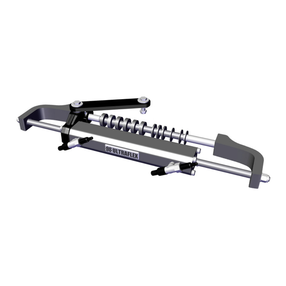
- Page 10 Installation and Maintenance Manual 1.4 Description of the cylinder The UC81 hydraulic cylinder is a front mounted hydraulic cylinder designed and built to be used as a component of a hydraulic steering system as described in the previous section. The cylinder is applied to the tilt tube of motors available on the market, as set out in the "Application guide"...
- Page 11 222 kg - 489 Ibs (@55 bar) Inner diameter 27.4 mm - 1,08” Stroke 186 mm - 7,3” OL150 ULTRAFLEX Operating max pressure 5,5 MPa (55 bar) (800 psi) 574 mm - 22,6 ‘‘ CAUTION The cylinder’s thrust is a theoretical thrust calculated with a system pressure of 55 bar, obtainable using UP18 pumps.
- Page 12 Installation and Maintenance Manual 2 - TRANSPORT 2.1 General warnings for product handling The weight of the product, including the packaging, is 8 Kg (18 pounds) and therefore it can be handled manually. CAUTION The staff handling the load must operate using all required PPE (individual protection devices) as required by the applicable standard on accident prevention at the workplace.
- Page 13 Installation and Maintenance Manual CONTENT OF THE STANDARD PACKING: No. 1 cylinder "Bullhorn" brackets 1 motor tube shaft kit composed of: • motor tube shaft (2 pieces) • 2 self-locking nuts + 2 washers • 1 key for motor shaft No.
- Page 14 Installation and Maintenance Manual 3 - INSTALLATION 3.1 Cockpit minimum requirements Before installing the cylinder it is necessary to ascertain that the dimensions of the cockpit are well suited to the upwards rotation of the outboard motor (Tilt) without the cylinder comes into contact with the cockpit itself.
- Page 15 Installation and Maintenance Manual WARNING MOUNTING THE MOTOR TO THE TRANSOM WITH JACK PLATE. The installation of a jack plate will change all of the clearances required for the application. A new check of clearances must be completed with the rotation of the motor in conjunction with the vertical movement of the jack plate in all possible positions.
- Page 16 Installation and Maintenance Manual 3.3 INSTALLATION OF THE CYLINDER WARNING Before proceeding with the installation of the product, ensure that you meet the requirements for a correct application mentioned in section 1.3 - "Configurations" and 3.1 - "Cockpit minimum requirements". NOTE is not liable for any damages caused by the contact between the cylinder and motor and/ or boat parts.
- Page 17 Installation and Maintenance Manual STARBOARD CONFIGURATION PORT CONFIGURATION Push the stem unit it stops. Using the Torx T30 wrench remove the screws (1) and the relevant washers in stainless steel (2). - page HYDRAULIC CYLINDER FOR OUTBOARD MOTOR...
- Page 18 Installation and Maintenance Manual Pull the cap with extension (3) and remove the 4 O-Rings (4) from their seats. CAUTION When removing the cap with the extension (3) it is necessary to hold the rod (5) so that the head does not protrudes (6).
- Page 19 Installation and Maintenance Manual Fasten the plug with the extension on the new position with the relevant screws and washers, with a tightening torque of 10 Nm (7,4 lb ft). CAUTION Take care that the key (8) and the head (9) coincide. In repositioning the cap the plastic head should NOT be rotated or moved.
- Page 20 Installation and Maintenance Manual The cylinder is now in "port" configuration. WARNING The hex head screw (10) is fixed at the bottom with a safety punching; DONOT try to unscrew for any reason. Proceed installing the cylinder. 3.3.2 Assembly of the cylinder After removing the protective caps of the fittings (1), manually centre the rod (2) with respect to the body of the cylinder (3).
- Page 21 Installation and Maintenance Manual Place the motor straight so that its arm is perpendicular to the transom. Referring to the installation instructions of the arm shown in the "Application Guide", connect the idler arm to the motor arm through the screw (4) and tighten with a torque of 30 Nm (22,1 lb ft).
- Page 22 Installation and Maintenance Manual Insert the first part of the motor tube (6) into the motor tube. N OTE The motor tube rod is divided into two separate parts so as to facilitate the installation in the event of a cockpit with reduced dimensions. Join the second part of the motor tube shaft (7) to the first and, insert the key (8).
- Page 23 Installation and Maintenance Manual Complete insertion of the motor tube shaft. Position the screw (9) and the relevant nut (10) on the fine adjusting ring nut (11) and screw it on the starboard side of the motor tube until it reaches its end stroke. - page HYDRAULIC CYLINDER FOR OUTBOARD MOTOR...
- Page 24 Installation and Maintenance Manual Referring to the "Application Guide" identify the spacers needed to be placed on the motor rod. AVERAGE WIDE CLOSE NOTE In this phase, make sure that the cylinder body is perfectly centred with respect to the rod and that the motor is perfectly perpendicular to the transom.
- Page 25 Installation and Maintenance Manual Position temporarily the bullhorns, without mounting them with the nuts, both on the cylinder’s stem and on the motor rod. Locate the spacers (15) to be used to compensate for the space between the ring nut and bullhorn and between tube and motor bullhorn, considering the thickness of the stainless steel washer (16).
- Page 26 Installation and Maintenance Manual Insert the plastic spacers and the two stainless steel washers on the motor rod. CAUTION The stainless steel washers must be both positioned towards the motor tube, on the opposite side with respect to the bullhorns to prevent their wear during lifting and lowering of the motor.
- Page 27 Installation and Maintenance Manual Insert the washers (18) on the two ends of the stem and screw in the nuts (19) with a tightening torque of 35 Nm (25,8 lb ft) and galling-proof grease such as MOLYKOTE® 1000. Insert the washers (20) on the two ends of the stem and screw in the nuts (21) with a tightening torque of 35 Nm (25,8 lb ft), and galling-proof grease such as MOLYKOTE®...
- Page 28 Installation and Maintenance Manual Loosen the locking screw (22) of the fine adjusting ring nut (23), unscrew the latter by hand and bring it abuts the stainless steel washers, until complete recovery of clearances. CAUTION Do not force the adjustment ring nut with tools or pliers. Check proper installation of the cylinder by manually moving the motor to the right and left, there must be no interference between cylinder and parts of the motor and of the boat.
- Page 29 Installation and Maintenance Manual Tighten the screw (25) of the fine adjusting ring nut (26) with a torque of 3 Nm (2,2 lb ft). Again check the correct movement of the motor during both left / right steering and during the tilt-back rotation.
- Page 30 Installation and Maintenance Manual The fittings are mounted in parallel and with an inclination of 30°. Screw the tubes on the cylinder fittings with a tightening torque of 20 Nm (15 lb ft) in accordance with the following: • 75 mm minimum bending radius of tubes •...
- Page 31 Installation and Maintenance Manual Steering system unit UP18 Cylinder UC81 Bleed valves 3.5 Filling and bleeding After the first installation and after any maintenance you must fill the system with hydraulic oil. This operation is intended to completely remove the air from the system ensuring its proper operation.
- Page 32 Installation and Maintenance Manual NOTE The filling and venting operations can be facilitated using the automatic venting equipment BUBBLE BLUSTER (supplied separately). CAUTION Use “OL 150” oil or compatible oil. “OL150” hydraulic oil is specifically formulated for for the purpose of maintaining longer in time the high qualitative level and performance of the products.
- Page 33 Installation and Maintenance Manual 3.5.1 Positioning the oil bottle The oil filler kit will be needed in order to carry out this operation (1 pin, 1 transparent pipe, 1 hose carrier fitting and 1 oil bottle spout), NOT supplied as standard. •...
- Page 34 Installation and Maintenance Manual 3.5.2 Oil filling and bleeding procedure N OTE The procedure is valid for both "starboard" and "port" configurations. Unscrew the two purge valves and manually move the body of the cylinder in abutment on one side as shown in the figure. Place the bottle of oil as indicated in section 3.5.1.
- Page 35 Installation and Maintenance Manual When the bleed valve begins to drain oil completely free of air bubbles, close the bleed valve and then continue turning the steering wheel in the same direction in order to fill the cylinder chamber. During this phase the cylinder body will move towards the opposite direction until the stroke end.
- Page 36 Installation and Maintenance Manual 4 - SAFETY WARNINGS This section aims to illustrate the safety rules to be followed for proper use of the equipment. It is recommended to read this section very carefully. It is recommended to read the manuals supplied with the other components of the steering system.
- Page 37 3.5 - "Filling and bleeding." Cleanse the system using water and mild and non-abrasive soap. CAUTION Use only OL150 ULTRAFLEX oil, or compatible hydraulic oils, as referred to in “Filling and bleeding” sections. - page HYDRAULIC CYLINDER FOR OUTBOARD MOTOR...
- Page 38 Installation and Maintenance Manual 5.2 Steering Wheel Dismantling Use a specific extractor to remove the steering wheel from the pump shaft. CAUTION Do not use a hammer or other tools that could cause irreparable damage to the pump. 5.3 Troubleshooting CAUTION Whenever the following checks require the removal and / or disassembly of the components of the steering system, request for the assistance of qualified staff.
- Page 39 Installation and Maintenance Manual PROBLEM POSSIBLE CAUSE INTERVENTION Filling the system is difficult. • Presence of air in the • Repeat the filling and The air bubbles in the upper system. bleeding procedures of the part of the tank even after system.
- Page 40 Installation and Maintenance Manual PROBLEM POSSIBLE CAUSE INTERVENTION The steering gear can be • The steering wheel is too • Replace the steering wheel easily manoeuvred in the small. with a larger one. dock, but is stiff when the • CAUTION boat is in motion.
- Page 41 Installation and Maintenance Manual • Lack of thread sealant. • Empty the steering gear and • disassemble it. Remove the CAUTION fittings and clean the threads To seal the fittings do not (remove the oil). Place under any circumstances use the thread sealant, screw Teflon tape or adhesive tape.
- Page 42 Installation and Maintenance Manual 6 - DISMANTLING 6.1 Dismantling If for any reason the equipment is meant to be disposed of, it is necessary to observe some basic rules aimed at safeguarding the environment. CAUTION Sheathings, hoses, conduits and plastic components, or in any case not made with metal, shall be disassembled and disposed of separately.
- Page 43 Manuale di installazione e manutenzione CILINDRO IDRAULICO PER MOTORI FUORIBORDO UC 81 PARTNER...
- Page 44 Gentile Cliente, La ringraziamo per aver scelto un prodotto è da anni un punto di riferimento nei sistemi di guida nel settore della nautica da diporto e professionale. Da sempre la produzione è sinonimo di grande affidabilità e sicurezza. Tutti i prodotti sono progettati e prodotti per garantire sempre le prestazioni migliori, relativamente allo scopo per cui sono concepiti.
- Page 45 Manuale di installazione e manutenzione INDICE GENERALE REVISIONI DEL DOCUMENTO......................... 46 USO DEL MANUALE E SIMBOLOGIA IMPIEGATA..................47 LETTERA INFORMATIVA......................... 48 GARANZIA............................. 49 SEZIONE 1 - DESCRIZIONE DEL PRODOTTO FUNZIONAMENTO DI UN SISTEMA DI GUIDA IDRAULICO............50 AVVERTENZE PER IL CORRETTO UTILIZZO DEL PRODOTTO............ 51 CONFIGURAZIONI.........................
- Page 46 Manuale di installazione e manutenzione REVISIONI DEL DOCUMENTO REV. DATE DESCRIZIONE REVISIONE 12/09/2013 Prima edizione. 07/05/2014 Aggiornamento a 39kn (45mph). 28/11/2014 Aggiornamento oli compatibili. 03/02/2015 Inseriti 4 O-Ring nel cilindro (pag.60) e 4 O-Ring di scorta da utilizzare in caso di passaggio da configurazione starboard/port. Inserita la coppia di serraggio per il fissaggio del tappo con estensione.
- Page 47 Manuale di installazione e manutenzione USO DEL MANUALE E SIMBOLOGIA IMPIEGATA Il MANUALE DI INSTALLAZIONE E MANUTENZIONE è il documento che accompagna il prodotto dal momento della sua vendita fino alla sua sostituzione e smaltimento. Risulta cioè essere parte integrante dello stesso. E’...
- Page 48 Manuale di installazione e manutenzione LETTERA INFORMATIVA Il presente manuale di installazione e manutenzione costituisce parte integrante del prodotto e deve essere facilmente reperibile dal personale addetto all’uso e alla manutenzione dello stesso. L’utilizzatore è tenuto a conoscere il contenuto del presente manuale. declina ogni responsabilità...
- Page 49 Manuale di installazione e manutenzione GARANZIA garantisce che i suoi prodotti sono costruiti a regola d’arte e che sono privi di difetti di fabbricazione e di materiali. Questa garanzia è valida per un periodo di 2 anni decorrenti dalla data di fabbricazione dei prodotti ad eccezione dei casi in cui questi siano installati ed usati su barche da lavoro o comunque su barche ad utilizzo commerciale, nel qual caso la garanzia è...
- Page 50 Manuale di installazione e manutenzione 1 - DESCRIZIONE DEL PRODOTTO 1.1 Funzionamento di un sistema di guida idraulico I sistemi idraulici di guida sono progettati in conformità alla normativa UNI EN ISO 10592 ed alla A.B.Y.C. P21. I sistemi di guida sono in grado di operare in un campo di temperatura ambiente compreso tra -18°C (0°F) e +77°C (+170°F), tutti i loro componenti sono stati realizzati specificatamente per l’ambiente marino, utilizzando materiali e processi di fabbricazione che offrono grande durata e...
- Page 51 Manuale di installazione e manutenzione 1.2 Avvertenze per il corretto utilizzo del prodotto ATTENZIONE Prima di iniziare l’installazione, riverificare la compatibilità di montaggio del cilindro UC81 al motore consultando l’allegato “Application Guide” contenuto nell’imballo. AVVERTENZA In qualsiasi caso non modificare il cilindro di guida per adattarlo alla Vostra applicazione. In questo caso il cilindro non opererà...
- Page 52 Manuale di installazione e manutenzione 1.4 Descrizione del cilindro Il cilindro idraulico UC81 è un cilindro idraulico fuoribordo a montaggio frontale progettato e costruito per essere utilizzato come componente di un sistema di guida idraulico come descritto nel paragrafo precedente. Il cilindro viene applicato al tubo di tiltaggio dei motori disponibili in commercio come riportato nell’allegato “Application guide”.
- Page 53 27,4 mm - 1.08” Diametro interno Corsa 186 mm - 7.3” Olio OL150 ULTRAFLEX Pressione massima di esercizio 5,5 MPa (55 bar) (800 psi) 574 mm - 22,6 ‘‘ ATTENZIONE La spinta del cilindro indicata è una spinta teorica calcolata con una pressione di sistema di 55 bar ottenibile utilizzando le pompe UP18.
- Page 54 Manuale di installazione e manutenzione 2 - TRASPORTO 2.1 Avvertenze generali per la movimentazione del prodotto Il peso del prodotto conprensivo di imballo è 8 Kg (18 pounds) e quindi la sua movimentazione può essere effettuata manualmente. ATTENZIONE Il personale addetto alla manipolazione del carico deve operare utilizzando tutti i D.P.I. (dispositivi di protezione individuale) come previsto dalla norma vigente per la prevenzione degli infortuni.
- Page 55 Manuale di installazione e manutenzione CONTENUTO DELL’ IMBALLO STANDARD: n°1 cilindro staffe “Bullhorn” n°1 kit asta tubo motore composto da: • asta tubo motore (2 pezzi) • n°2 dadi autobloccanti + n°2 rondelle • n°1 chiavetta per asta motore n° 1 kit distanziali composto da: •...
- Page 56 Manuale di installazione e manutenzione 3 - INSTALLAZIONE 3.1 Requisiti minimi del pozzetto Prima di procedere all’installazione del cilindro è necessario verificare che le misure del pozzetto siano idonee alla rotazione del motore fuoribordo verso l’alto (Tilt) senza che il cilindro entri in contatto con il pozzetto stesso. Di seguito sono indicate le dimensioni minime del pozzetto e dello specchio di poppa per garantire la corretta rotazione ed il funzionamento del cilindro di guida del motore.
- Page 57 Manuale di installazione e manutenzione AVVERTENZA APPLICAZIONE DEL MOTORE CON PIASTRA DI SOLLEVAMENTO (JACK PLATE) ALLO SPECCHIO DI POPPA. L’installazione di una piastra di sollevamento cambierà tutti gli spazi liberi d’applicazione richiesti. Un nuovo controllo dello spazio libero deve essere completato con la rotazione del motore in abbinamento con il movimento verticale della piastra di sollevamento in tutte le posizioni possibili.
- Page 58 Manuale di installazione e manutenzione 3.3 Installazione del cilindro AVVERTENZA Prima di procedere con l’installazione del prodotto, accertarsi di possedere i requisiti richiesti per una corretta applicazione riportati ai paragrafi 1.3 - “Configurazioni” e 3.1 - “Requisiti minimi del pozzetto”. NOTA non risponde di eventuali danni causati dal contatto tra il cilindro e parti del motore e/o dell’imbarcazione.
- Page 59 Manuale di installazione e manutenzione CONFIGURAZIONE STARBOARD CONFIGURAZIONE PORT Spingere lo stelo fino al suo arresto. Utilizzando la chiave Torx T30 rimuovere le viti (1) e le relative rondelle in acciaio inox (2). - pag. CILINDRO IDRAULICO PER MOTORE FUORIBORDO...
- Page 60 Manuale di installazione e manutenzione Sfilare il tappo con estenzione (3) e rimuovere i 4 O-Ring (4) dalla loro sede. ATTENZIONE Quando si smonta il tappo con estensione (3) è necessario tenere fermo lo stelo (5) in modo che non fuoriesca la testata (6). Inserire in sede i 4 nuovi O-Ring forniti in dotazione (7).
- Page 61 Manuale di installazione e manutenzione Fissare il tappo con estensione nella nuova posizione con le relative viti e rondelle, con una coppia di serraggio di 10 Nm (7,4 lb ft). ATTENZIONE Fare attenzione che la chiavetta (8) e la testata (9) coincidano. Nel riposizionamento del tappo la testata in plastica NON deve essere ruotata o spostata.
- Page 62 Manuale di installazione e manutenzione Il cilindro è ora in configurazione “port”. AVVERTENZA La vite a testa esagonale (10) è fissata nella parte inferiore con una punzonatura di sicurezza; NON tentare di svitarla per alcun motivo! Procedere con il montaggio del cilindro. 3.3.2 Montaggio del cilindro Dopo aver rimosso i tappi di protezione dei raccordi (1), centrare manualmente lo stelo (2) rispetto al corpo del cilindro (3).
- Page 63 Manuale di installazione e manutenzione Posizionare il motore dritto in modo che il suo braccetto risulti perpendicolare allo specchio di poppa. Facendo riferimento alle modalità di applicazione del braccetto riportate nella “Application Guide”, collegare il braccio di rinvio al braccetto motore tramite la vite (4) e serrarla con una coppia di serraggio di 30 Nm (22,1 lb ft).
- Page 64 Manuale di installazione e manutenzione Inserire la prima parte di asta tubo motore (6) nel tubo motore. NOTA L’asta tubo motore è divisa in due parti separate in modo da facilitare l’installazione in caso di pozzetto con misure ridotte. Unire la seconda parte di asta tubo motore (7) alla prima e, mantenendo le due parti unite, inserire la chiavetta (8).
- Page 65 Manuale di installazione e manutenzione Completare l’inserimento dell’asta tubo motore. Posizionare la vite (9) e il relativo dado (10) sulla ghiera di regolazione fine (11) e avvitare quest’ultima sul lato dritta (starboard) del tubo motore fino a portarla in battuta. - pag.
- Page 66 Manuale di installazione e manutenzione Facendo riferimento alla “Application Guide” individuare i distanziali necessari da posizionare sull’asta motore. NOTA In questa fase assicurarsi che il corpo del cilindro sia perfettamente centrato rispetto allo stelo e che il motore sia perfettamente perpendicolare rispetto allo specchio di poppa. Inserire le boccole dei bullhorn (12) sullo stelo (13), una per ogni lato.
- Page 67 Manuale di installazione e manutenzione Posizionare temporaneamente i bullhorn senza bloccarli con i dadi, sia sullo stelo del cilindro, sia sull’asta motore. Individuare i distanziali (15) da utilizzare per compensare lo spazio tra ghiera e bullhorn e tra tubo motore e bullhorn, considerando lo spessore della rondella in inox (16). ATTENZIONE Prevedere sempre un minimo di gioco tra distanziali e bullhorn tale da consentire la rotazione dell’asta all’interno del tubo motore.
- Page 68 Manuale di installazione e manutenzione Inserire i distanziali in plastica e le due rondelle inox sull’asta motore. ATTENZIONE Le rondelle inox devono essere posizionate entrambe verso il tubo motore dal lato opposto ai bulhorn per evitare l’usura degli stessi durante il sollevamento e l’abbassamento del motore. Inserire i due bullhorn avendo cura che le 2 boccole in acciaio (17) siano posizionate correttamente sullo stelo (come indicato al passaggio 10).
- Page 69 Manuale di installazione e manutenzione Inserire le rondelle (18) sulle due estremità dello stelo ed avvitare i dadi (19) con una coppia di serraggio 35 Nm (25,8 lb ft) e grasso antigrippaggio tipo MOLYKOTE® 1000. Inserire le rondelle (20) sulle due estremità dell’asta del tubo motore ed avvitare i dadi (21) con una coppia di serraggio 35 Nm (25,8 lb ft), dopo averli ingrassati con grasso antigrippaggio tipo MOLYKOTE®...
- Page 70 Manuale di installazione e manutenzione Allentare la vite di bloccaggio (22) della ghiera di regolazione fine (23), svitare a mano quest’ultima e portare in battuta sulla rondella in inox, fino al completo recupero dei giochi. ATTENZIONE Non forzare la ghiera di regolazione fine con attrezzi o pinze. Verificare la corretta installazione del cilindro muovendo manualmente il motore a destra e a sinistra;...
- Page 71 Manuale di installazione e manutenzione Serrare la vite (25) della ghiera di regolazione fine (26) con una coppia di serraggio di 3 Nm (2,2 lb ft). Verificare nuovamente il corretto movimento del motore sia durante la sterzata destra/ sinistra e sia durante la rotazione di tiltaggio. ATTENZIONE In questa fase deve essere riscontrato un gioco sufficiente ad evitare attriti ma non eccessivo da causare l’instabilità...
- Page 72 Manuale di installazione e manutenzione I raccordi sono montati paralleli e con un’inclianzione di 30°. Avvitare i tubi sui raccordi del cilindro con una coppia di serraggio di 20 Nm (15 lb ft) rispettando quanto segue: • raggio minimo di curvatura dei tubi 75 mm •...
- Page 73 Manuale di installazione e manutenzione Stazione di guida UP18 Cilindro UC81 Valvole di spurgo 3.5 Riempimento e spurgo Dopo la prima installazione e a seguito di eventuali interventi di manutenzione occorre eseguire l’operazione di riempimento del sistema con olio idraulico. Questa operazione ha lo scopo di eliminare completamente l’aria dall’impianto garantendo il buon funzionamento del sistema.
- Page 74 Manuale di installazione e manutenzione NOTA operazioni riempimento spurgo possono essere facilitate tramite l’utilizzo dell’attrezzatura di spurgo automatico BUBBLE BLUSTER (fornito a parte). ATTENZIONE Usare olio “OL 150” o oli compatibili. L’olio idraulico “OL150” è specificatamente formulato per allo scopo di mantenere più a lungo nel tempo l’alto livello qualitativo e di performance dei prodotti La sua particolare formula “Zinco Free”...
- Page 75 Manuale di installazione e manutenzione 3.5.1 Posizionamento della bottiglia dell’olio Per effettuare questa operazione è necessario il kit di riempimento olio (1 spillo, 1 tubo trasparente, 1 raccordo portatubo e 1 beccuccio per bottiglia olio) NON fornito in dotazione. • Rimuovere il tappo dalla pompa ed inserire il raccordo di riempimento. •...
- Page 76 Manuale di installazione e manutenzione 3.5.2 Procedura di riempimento e spurgo NOTA La procedura è valida sia per configurazione “starboard” che “port”. Svitare le due valvole di spurgo e portare manualmente il corpo del cilindro in battuta da un lato come indicato in figura. Posizionare la bottiglia dell’olio come indicato al paragrafo 3.5.1.
- Page 77 Manuale di installazione e manutenzione Quando dalla valvola di spurgo comincia a defluire olio completamente privo di bolle d’aria, chiudere la valvola di spurgo e continuare quindi a ruotare il volante nella stessa direzione al fine di riempire la camera del cilindro.
- Page 78 Manuale di installazione e manutenzione 4 - AVVERTENZE DI SICUREZZA Questa sezione ha lo scopo di illustrare le norme di sicurezza da seguire per un uso corretto dell’apparecchiatura. Si raccomanda di leggere con molta attenzione questa sezione. Si raccomanda di leggere i manuali forniti con gli altri componenti del sistema di guida. 4.1 Norme di sicurezza durante l’installazione e l’uso RISPETTATE TASSATIVAMENTE le precauzioni ed i criteri di sicurezza indicati qui di seguito.
- Page 79 Manuale di installazione e manutenzione 4.2 Abbigliamento ATTENZIONE Durante le fasi di installazione, ispezione o manutenzione E’ SEVERAMENTE PROIBITO indossare collane, braccialetti o indumenti che potrebbero impigliarsi in parti in movimento. ATTENZIONE Il personale addetto alla manipolazione del carico deve operare utilizzando tutti i D.P.I. (dispositivi di protezione individuale) come previsto dalla norma vigente per la prevenzione degli infortuni.
- Page 80 Manuale di installazione e manutenzione 5.2 Smontaggio Volante Per estrarre il volante dall’albero della pompa, utilizzare un apposito estrattore. ATTENZIONE Non utilizzare il martello o altri utensili che potrebbero danneggiare in maniera irreparabile la pompa. 5.3 Ricerca guasti ATTENZIONE Ogni qualvolta i seguenti controlli richiedano la rimozione e/o lo smontaggio dei componenti del sistema di guida, richiedere l’intervento di personale qualificato.
- Page 81 Manuale di installazione e manutenzione PROBLEMA POSSIBILE CAUSA INTERVENTO Il sistema è difficile da • Presenza di aria nel • Ripetere la procedura di riempire. sistema. riempimento e spurgo del L’aria gorgoglia nella parte sistema. alta del serbatoio della • Installare i tubi in timoneria anche dopo aver orizzontale e in ogni caso riempito totalmente il...
- Page 82 Manuale di installazione e manutenzione PROBLEMA POSSIBILE CAUSA INTERVENTO La timoneria si manovra • Il volante di guida è • Sostituire il volante di agevolmente in banchina, troppo piccolo. guida con uno più grande. ma diventa rigida quando • ATTENZIONE l’imbarcazione è...
- Page 83 Manuale di installazione e manutenzione • Mancanza di fluido • Svuotare la timoneria sigilla raccordi. e smontarla. Togliere • i raccordi e pulire le ATTENZIONE filettature dall’olio. Per sigillare i raccordi Posizionare il fluido non utilizzare in nessun sigilla raccordi, avvitare caso nastro teflon o nastro i raccordi, installare la adesivo.
- Page 84 Manuale di installazione e manutenzione 6 - SMANTELLAMENTO 6.1 Smantellamento Qualora si intenda, per qualsiasi motivo, mettere fuori servizio il sistema di guida, è necessario osservare alcune regole fondamentali atte a salvaguardare l’ambiente. ATTENZIONE Guaine, condotti flessibili, componenti di materiale plastico o comunque non metallico, dovranno essere smontati e smaltiti separatamente.
- Page 85 Manuel d'installation et de maintenance CYLINDRE HYDRAULIQUE POUR MOTEURS HORS BORD UC 81 PARTNER...
- Page 86 Cher Client, Nous vous remercions d'avoir choisi un produit est depuis des années une référence en matière de systèmes de conduite dans le secteur nautique de plaisance et professionnel. Depuis toujours la production est synonyme de grande fiabilité et sécurité. Tous les produits sont conçus et produits pour toujours garantir les meilleures prestations, pour atteindre l'objectif pour lequel ils ont été...
- Page 87 Manuel d'installation et de maintenance INDEX GENERAL RÈVISION DE DOCUMENTS........................88 UTILISATION DU MANUEL ET EXPLICATION DES SYMBOLES..............89 LETTRE D'INFORMATION........................90 GARANTIE............................. 91 CHAPITRE 1 - DESCRIPTION DU PRODUIT FONCTIONNEMENT D'UN SYSTEME DE CONDUITE HYDRAULIQUE.......... 92 CONSIGNES POUR LA BONNE UTILISATION DU PRODUIT............93 CONFIGURATIONS........................
- Page 88 Manuel d'utilisation et de maintenance RÉVISION DE DOCUMENTS REV. DATE DESCRIPTION DE RÉVISION 12/09/2013 Première édition. 07/05/2014 Mise à niveau vers 39kn (45 mph). 28/11/2014 Mise à niveau des huiles compatibles. 03/02/2015 N° 4 joints toriques insérés dans le cylindre (p.102) et n° 4 joints toriques de rechange à...
- Page 89 Manuel d'installation et de maintenance UTILISATION DU MANUEL ET EXPLICATION DES SYMBOLES LE MANUEL D'INSTALLATION ET DE MAINTENANCE est le document qui accompagne le produit à partir du moment de sa vente jusqu'à son remplacement et élimination. Il fait donc partie intégrante du produit.
- Page 90 Manuel d'utilisation et de maintenance LETTRE D'INFORMATION Le présent manuel d'installation et de maintenance fait partie intégrante du produit et doit être facilement accessible par le personnel en charge de l'utilisation et de la maintenance du produit. L'utilisateur est tenu de connaître le contenu du présent manuel. décline toute responsabilité...
- Page 91 Manuel d'installation et de maintenance GARANTIE garantit que ses produits sont construits dans les règles de l'art et qu'ils sont sans défauts de fabrication et de matériaux. Cette garantie est valable pendant 2 ans à compter de la date de fabrication des produits à...
- Page 92 Manuel d'utilisation et de maintenance 1 - DESCRIPTION DU PRODUIT 1.1 Fonctionnement d'un système de conduite hydraulique Les systèmes hydrauliques de conduite sont conçus conformément à la norme UNI EN ISO 10592 et à la A.B.Y.C. P21. Les systèmes de conduite sont en mesure de fonctionner dans une plage de température ambiante comprise entre -18°C (0°F) et +77°C (+170°F);...
- Page 93 Manuel d'installation et de maintenance 1.2 Coonsignes pour la bonne utilisation du produit ATTENTION Avant de commencer l'installation, revérifier la compatibilité de montage du cylindre UC81 au moteur en consultant l'annexe "Application Guide" contenu dans l'emballage. AVERTISSEMENT Ne modifier en aucun cas le cylindre de conduite pour l'adapter à votre application. Dans ce cas le cylindre ne fonctionnera pas en sécurité...
- Page 94 Manuel d'utilisation et de maintenance 1.4 Description du cylindre Le cylindre UC81 est un cylindre hydraulique hors bord à montage frontal conçu et construit pour être utilisé comme composant d'un système de conduite comme décrit dan le paragraphe précédent. Le cylindre est appliqué au tuyau de tiltage des moteurs disponibles dans le commerce comme reporté...
- Page 95 Diamètre interne 27,4 mm - 1.08” Course 186 mm - 7.3” Huile OL150 ULTRAFLEX Pression maximale de service 5,5 MPa (55 bar) (800 psi) 574 mm - 22,6 ‘‘ ATTENTION L’impulsion du cylindre indique une impulsion théorique calculée avec une pression de système de 55 bars qui peut être obtenu en utilisant des pompes UP18.
- Page 96 Manuel d'utilisation et de maintenance 2 - TRANSPORT 2.1 Mises en garde générales pour le déplacement du produit Le poids du produit avec l'emballage est de 8 kg (9.92 pounds) et son déplacement peut donc être effectué manuellement. ATTENTION Le personnel en charge de la manipulation du chargement doit opérer en utilisant tous les EPI. (Dispositifs de protection individuelle) comme le prévoit la norme en vigueur pour la prévention des accidents.
- Page 97 Manuel d'installation et de maintenance CONTENU DE L'EMBALLAGE STANDARD : 1 cylindre équerres “Bullhorn” n°1 kit tige tuyau moteur composé de: • tuyau moteur (2 pièces) • n°2 écrous autobloquants + n°2 rondelles • n°1 robinet pour tige moteur 1 kit écarteurs composé de : •...
- Page 98 Manuel d'utilisation et de maintenance 3 - INSTALLATION 3.1 Conditions minimums requises du pont Avant de procéder à l'installation du cylindre il est nécessaire de vérifier que les mesures du pont soient adaptées à la rotation du moteur hors bord vers le haut (Tilt) sans que le cylindre entre en contact avec le pont.
- Page 99 Manuel d'installation et de maintenance AVERTISSEMENT APPLICATION DU MOTEUR AVEC PLAQUE DE LEVAGE (JACK PLATE) AU NIVEAU DU RELEVE DE VARANGUE. L'installation d'une plaque de levage changera tous les espaces libres d'application nécessaires. Un nouveau contrôle de l'espace doit être effectué avec la rotation du moteur en association avec le mouvement vertical de la plaque de levage dans toutes les positions possibles.
- Page 100 Manuel d'utilisation et de maintenance 3.3 Installation du cylindre AVERTISSEMENT Avant de procéder à l'installation du produit, s'assurer de posséder les conditions nécessaires pour une application correcte, reportés aux paragraphes 1.3 - "Configurations" et 3.1 - "Conditions minimums requises du pont". NOTE ne répond pas des éventuels dommages causés par le contact entre le cylindre et des pièces du moteur et/ou de l'embarcation.
- Page 101 Manuel d'installation et de maintenance CONFIGURAZIONE STARBOARD CONFIGURAZIONE PORT Pousser la tige jusqu’à son arrêt. Enlever les vis (1) et les rondelles en acier inox correspondantes (2) en utilisant la clé Torx T30. - page CYLINDRE HYDRAULIQUE POUR MOTEUR HORS BORD...
- Page 102 Manuel d'utilisation et de maintenance Retirer le bouchon avec extension (3) et retirer les 4 joints toriques (4) de leur siège. ATTENTION Lors du démontage du bouchon avec extension (3), il faut tenir fermement l'axe (5) de sorte à ne pas faire sortir la tête (6).
- Page 103 Manuel d'installation et de maintenance Fixer le bouchon avec extension dans la nouvelle position avec les vis et les rondelles correspondantes, avec un couple de serrage de 10 Nm (7,4 lb ft). ATTENTION Faire attention à ce que la clavette (8) et la tête (9) coïncident. Lors du repositionnement du bouchon, la tête en plastique NE doit PAS être tournée ou déplacée.
- Page 104 Manuel d'utilisation et de maintenance Le cylindre est maintenant en configuration "port". AVERTISSEMENT La vis à tête hexagonale (10) est fixée dans la partie inférieure avec un poinçonnage de sécurité; NE tenter de dévisser en aucun cas! Procéder au montage du cylindre. 3.3.2 Montage du cylindre Après avoir retiré...
- Page 105 Manuel d'installation et de maintenance Positionner le moteur droit de sorte à ce que le bras soit perpendiculaire au tableau arrière. En faisant référence aux modalités d'application du bras reportées dans la "Application Guide", raccorder le bras de renvoi au bras moteur par l'intermédiaire de la vis (4) et ma serrer avec un couple de serrage de 30 Nm (22,1 lb ft).
- Page 106 Manuel d'utilisation et de maintenance Insérer la première partie de tige tuyau moteur (6) dans le tuyau moteur. NOTE La tige tuyau moteur est divisé en deux parties séparées de sorte à faciliter l'installation en cas de pont avec des mesures réduites. Unir la seconde partie de la tige tuyau moteur (7) à...
- Page 107 Manuel d'installation et de maintenance Compléter l’insertion de la tige tuyau moteur. Positionner la vis (9) et l'écrou (10) correspondant sur la bague de réglage fin (11) et visser cette dernière sur le côté droit du tuyau moteur jusqu'à l'amener jusqu'à la butée. - page CYLINDRE HYDRAULIQUE POUR MOTEUR HORS BORD...
- Page 108 Manuel d'utilisation et de maintenance En faisant référence à l'“Application Guide” identifier les écarteurs nécessaires à placer sur la tige moteur. GRAND MOYEN FILTRER NOTE Pour cette phase, s'assurer que le corps du cylindre soit parfaitement centré par rapport à l'axe et que le moteur soit parfaitement perpendiculaire par rapport au tableau arrière. Insérer les bagues des bullhorn (12) sur l'axe (13), une pour chaque côté.
- Page 109 Manuel d'installation et de maintenance Positionnez provisoirement les clés de serrage sans les bloquer avec les écrous, soit sur la tige du cylindre soit sur la jauge du moteur. Identifier les écarteurs (15) à utiliser pour compenser l'espace entre bague et bullhorn et entre tuyau moteur et bullhorn, en tenant compte de l'épaisseur de la rondelle en inox (16).
- Page 110 Manuel d'utilisation et de maintenance Insérer les écarteurs en plastique et les deux rondelles en inox sur la tige moteur. ATTENTION Les rondelles inox doivent être positionnées vers le tuyau moteur du côté opposé aux bullhorn pour éviter l'usure de ces derniers durant le soulèvement et la descente du moteur. Insérer les deux bullhorn en vérifiant que les 2 bagues en acier (17) soient correctement placées sur l'axe (comme indiqué...
- Page 111 Manuel d'installation et de maintenance Insérer les rondelles (18) sur les deux extrémités de la tige et visser les écrous (19) avec un couple de serrage 35 Nm (25,8 lb ft) et de la graisse anti-grippage de type MOLYKOTE® 1000. Insérer les rondelles (20) sur les deux extrémités de la tige tuyau moteur et visser les écrous (21) avec un couple de serrage 35 Nm (25,8 lb ft) et de la graisse anti-grippage de type MOLYKOTE®...
- Page 112 Manuel d'utilisation et de maintenance Desserrer la vis de blocage (22) de la bague de réglage fin (23), dévisser à la main cette dernière et la mettre contre la rondelle en inox, jusqu'à la récupération totale des jeux. ATTENTION Ne pas forcer la bague de réglage fin avec des outils ou des pinces. Vérifier l'installation du cylindre en déplaçant manuellement le moteur à...
- Page 113 Manuel d'installation et de maintenance Serrer la vis (25) de la bague de réglage fin (26) avec un couple de serrage de 3 Nm (2,2 lb ft). Vérifier de nouveau le mouvement du moteur, aussi bien durant le braquage droite/gauche que durant la rotation de tiltage.
- Page 114 Manuel d'utilisation et de maintenance Les raccords sont montés parallèlement et avec une inclinaison de 30°. Visser les tuyaux sur les raccords du cylindre avec un couple de serrage de 20 Nm (15 lb ft) en respectant ce qui suit : •...
- Page 115 Manuel d'installation et de maintenance Station de conduite UP18 Cylindre UC81 Robinets de purge 3.5 Remplissage et purge Après la première installation et à la suite d'éventuelles interventions de maintenance, il faut effectuer l'opération de remplissage du système avec de l'huile hydraulique. Cette opération a pour objectif d'éliminer complètement l'air de l'installation et de garantir le bon fonctionnement du système.
- Page 116 Manuel d'utilisation et de maintenance NOTE Les opérations de remplissage et de purge peuvent être facilitées par l'utilisation de l'outillage de purge automatique BUBBLE BLUSTER (fourni séparément). ATTENTION Utiliser l’huile “OL 150” ou des huiles compatibles. L’huile hydraulique “OL150” est spécialement formulée pour afin de maintenir plus durablement le haut niveau qualitatif et de performance des produits Sa formule particulière “Zinc Free”...
- Page 117 Manuel d'installation et de maintenance 3.5.1 Mise en place de la bouteille d'huile Pour effectuer cette opération, il faut le kit de remplissage huile (1 épingle, 1 tuyau transparent, 1 raccord porte-tuyau et 1 goulot pour bouteille huile) NON fourni. •...
- Page 118 Manuel d'utilisation et de maintenance 3.5.2 Procédure de remplissage et de purge NOTE La procédure est valable aussi bien pour la configuration "starboard" que "port". Dévisser les deux robinets de purge et mettre manuellement le corps du cylindre jusqu'à la butée d'un côté comme indiqué en figure.
- Page 119 Manuel d'installation et de maintenance Quand de l'huile exempte de bulles d'air commence à couler du robinet de purge, fermer le robinet et continuer à tourner le volant dans la même direction dans le but de remplir la chambre du cylindre. Durant cette phase, le corps du cylindre se déplacera vers la direction opposée jusqu'à...
- Page 120 Manuel d'utilisation et de maintenance 4 - CONSIGNES DE SECURITE Ce chapitre a pour objectif d'illustrer les normes de sécurité à suivre pour une utilisation correcte de l'appareil; Il est recommandé de lire ce chapitre avec beaucoup d'attention. Il est recommandé de lire les manuels fournis avec les autres composants du système de conduite.
- Page 121 3.5 - "Remplissage et purge". Nettoyer le système avec de l'eau et du savon non agressif et non abrasif. ATTENTION Utiliser de l’huile ne OL150 ULTRAFLEX, ou des huiles hydrauliques compatibles indiquées au paragraphe “Remplissage et purge”. - page...
- Page 122 Manuel d'utilisation et de maintenance 5.2 Démontage Volant Pour extraire le volant de l’arbre de la pompe, utiliser un extracteur approprié. ATTENTION Ne pas utiliser le marteau ou d’autres outils qui pourraient endommager la pompe de manière irréparable. 5.3 Recherche des pannes ATTENTION A chaque fois que les contrôles suivants requièrent le retrait et/ou le démontage des composants du système de conduite, demander l'intervention d'un personnel qualifié.
- Page 123 Manuel d'installation et de maintenance PROBLEME CAUSE POSSIBLE INTERVENTION Le système est difficile à • Présence d'air dans le • Répéter la procédure de remplir. système. remplissage et de purge du L'air gargouille dans la système. partie haute du réservoir de •...
- Page 124 Manuel d'utilisation et de maintenance PROBLEME CAUSE POSSIBLE INTERVENTION La timonerie de direction • Le volant de conduite est • Remplacer le volant de se manœuvre facilement trop petit. conduite par un plus grand. à quai, mais devient rigide • ATTENTION quand l'embarcation est en mouvement.
- Page 125 Manuel d'installation et de maintenance • Absence de fluide de • Vider la timonerie de fixation des raccords. direction et la démonter. Retirer les raccords et ATTENTION nettoyer l'huile dans les Pour sceller les raccords, filetages. Mettre du fluide n'utiliser en aucun cas du de fixation pour raccords, ruban de téflon ou du ruban visser les raccords, installer...
- Page 126 Manuel d'utilisation et de maintenance 6 - ELIMINATION 6.1 Elimination En cas d'intention, quel qu'en soit le motif, de mettre le système de conduite hors service, il faut respecter certaines règles fondamentales en mesure de protéger l'environnement. ATTENTION Les gaines, conduits flexibles, composants en plastique ou dans tous les cas non métalliques, devront être démontés et éliminés séparément.
- Page 127 notes...
- Page 128 S.p.A. 16015 Casella (Genova) Italia - Via Crose, 2...
- Page 129 Installation instructions HEAD REPLACEMENT KIT UC 81 CYLINDER Istruzioni di installazione KIT SOSTITUZIONE TESTATE CILINDRO UC 81 Instructions de montage KIT DE REMPLACEMENT TETES VERIN UC 81 PARTNER (REV. 0) (Dr./Dis./Des. n° 34818 11/12/2019)
- Page 130 ULTRAFLEX type de produit décrit ne changent nute nel manuale. Ferme restando pas, la Société ULTRAFLEX se réserve reserves the right to make those le caratteristiche essenziali del pro- modifications, such as descriptions,...
- Page 131 Les composants des systèmes de conduite ULTRAFLEX sont pourvus de the boats marked CE. We inform you Assistenza. that the ULTRAFLEX warranty is null if I componenti dei sistemi di guida la marque en conformité avec la some ULTRAFLEX components are...
- Page 132 Questo kit deve essere utilizzato Ce kit doit être utilisé seulement hydraulic cylinders for outboard esclusivamente con cilindro idraulico avec vérin hydraulique pour engines UC 81 only. per motori fuoribordo UC 81. moteurs hors-bord UC 81. CAUTION ATTENZIONE ATTENTION During replacement Durante l’intera procedura di...
- Page 133 ULTRAFLEX SVUOTAMENTO SYSTEM VIDANGE SYSTEME IMPIANTO DRAINING Before removing the cylinder from Prima di procedere con la Avant d’enlever le vérin du the tilt tube, it is necessary to rimozione del cilindro dal tubo tuyau faut vider completely drain the oil from the motore è...
- Page 134 ULTRAFLEX Close bleed valve “1”, open Chiudere la valvola di Fermer soupape the other valve and move the spurgo “1”, aprire l'altra valvola vidange “1”, ouvrir l'autre purged oil tank to the other side. e posizionare il contenitore di soupape et positionner le bac de Turn the steering wheel slowly as recupero dell'olio dall'altra parte.
- Page 135 ULTRAFLEX RIMOZIONE DEL CYLINDER DESASSEMBLAGE DU CILINDRO REMOVAL VERIN CAUTION ATTENZIONE ATTENTION Before replacing heads, remove Prima procedere alla Avant de remplacer les têtes the cylinder from the engine then sostituzione delle testate occorre il faut enlever le vérin du...
- Page 136 ULTRAFLEX Remove tilt tube rod “5”. Sfilare l’asta motore “5”. Extraire la tige moteur “5”. By means of a 9/16” wrench, Utilizzando una chiave da 9/ 8 Enlever l’écrou “6” qui bloque le remove nut “6” connecting the 16” rimuovere il dado “6” che bras au moteur à...
- Page 137 PORT) refer to the instructions occorre fare riferimento a quanto BABORD GAUCHE) il faut consulter described in paragraph 3.3 of the riportato nel manuale UC 81 al tout ce qui est indiqué dans le UC 81. paragrafo 3.3. manuel UC 81 au paragraphe 3.3.
- Page 138 ULTRAFLEX After completely removing Dopo aver rimosso Après avoir enlevé one of the two screws and its completamente uno dei due dadi complètement une des deux vis et washer, remove its bullhorn. e la relativa rondella sfilare il la rondelle relative extraire son relativo bullhorn.
- Page 139 ULTRAFLEX By using two 9/16” wrenches Utilizzando due chiavi da 9/ En utilisant deux clés de 9/ at the same time (as shown in 16” contemporaneamente come 16” simultanément comme picture), unscrew the nut from the illustrato in figura, svitare il dado indiqué...
- Page 140 ULTRAFLEX Remove the cap equipped Rimuovere il tappo con Enlever le bouchon pourvu with extension “14”. estensione “14”. d’extension “14”. 18 Remove the four O-rings “15” Rimuovere i quattro O-ring 18 Enlever les quatre O-ring “15” from their seat. “15” dalla loro sede.
- Page 141 ULTRAFLEX 19 By means of pliers extract the 19 Con una pinza sfilare la 19 A l’aide d’une pince extraire la tête “17” qui doit être head “17” to be replaced. testata “17” da sostituire. remplacée. Put the proper tool “18” on Senza muovere lo stelo Positionner l’outil spécial “18”...
- Page 142 ULTRAFLEX Fit the new head on the rod Imboccare la nuova testata Placer la nouvelle tête sur le and insert it into the cylinder as sullo stelo e inserirla nel cilindro piston et l’insérer dans le vérin shown in the picture.
- Page 143 25 Procedere all’installazione 25 Installer le vérin selon les the instructions provided in del cilindro seguendo quanto instructions du paragraphe 3.3 du paragraph 3.3 of the UC 81 riportato al paragrafo 3.3 del manuel UC 81. manual. manuale UC 81.
- Page 144 ULTRAFLEX S.p.A. 16015 Casella (Genova) Italia - Via Crose, 2...