Chapitres
Table des Matières
Dépannage

Manuels Connexes pour Ultraflex UC 68-OBS


Sommaire des Matières pour Ultraflex UC 68-OBS
- Page 1 Installation and Maintenance Manual HYDRAULIC CYLINDERS FOR SIDE MOUNT APPLICATIONS UC 68-OBS UC 132-OBS UC 133-IOB PARTNER pag. 23 page. 45 page. 2 (Dr. No. 23021/e 16/07/2019)
- Page 2 Products for pleasure boats are constantly tested to check their conformity with the 2013/53/EU. "ULTRAFLEX has over 80 years of experience in the marine industry and is a world leader in the production of mechanical, hydraulic and electronic steering systems, control boxes and steering wheels for any kind of pleasure, fishing or commercial boats.
-
Page 3: Table Des Matières
ULTRAFLEX Installation and Maintenance Manual TABLE OF CONTENTS MANUAL USE AND SYMBOLS USED........................4 INTRODUCTION..........................5 W A R R A N T Y ................... . . 5 SECTION 1 - PRODUCT DESCRIPTION HYDRAULIC STEERING SYSTEM OPERATION..................6... -
Page 4: Manual Use And Symbols Used
ULTRAFLEX Installation and Maintenance Manual MANUAL USE AND SYMBOLS USED THE INSTALLATION AND MAINTENANCE MANUAL is the document accompanying the product from its sale to its replacement and discharge. The manual is an important part of the product itself. It is necessary to read carefully the manual, before ANY ACTIVITY involving the product, handling and unloading included. -
Page 5: Introduction
We remind you that only marked steering systems must be used on the boats marked . We inform you that the ULTRAFLEX warranty is null if some ULTRAFLEX components are installed on a steering system together with products of other brands. page 5... -
Page 6: Product Description
WARNING The UC 68-OBS, UC 132-OBS and UC 133-IOB side mount cylinders must not be installed on race boats. WARNING Dual engine applications require two steering cylinders and tie bar, when the combined engine horsepower exceeds 450hp, and/or when the boat speed exceeds 55 m.p.h. -
Page 7: Configurations
Installation and Maintenance Manual 1.3 Configurations The hydraulic cylinders for side mount installations UC 68-OBS, UC 132-OBS, UC 133-IOB model can be installed with different configurations according to the number and the type of engines used with a single or dual engine steering system. -
Page 8: Cylinder Description
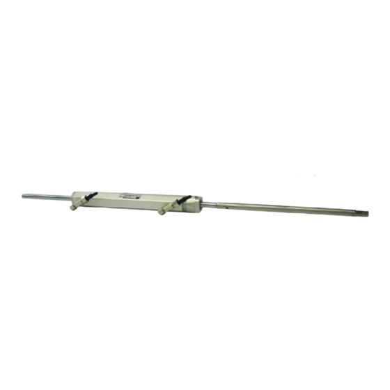
Installation and Maintenance Manual 1.4 Cylinder description UC 68-OBS, UC 132-OBS and UC133-IOB are hydraulic side mount cylinders which have been designed and manufactured to be used as a component in the hydraulic steering systems, as described in the previous paragraph. -
Page 9: Transport
Before using the equipment check that the product has not been damaged during transport. Also make sure that all the standard components are in the packaging (see list). In case of damage, notify the claim to the forwarder and inform the supplier. UC 68-OBS UC 132-OBS UC 133-IOB CONTENTS OF THE STANDARD PACKAGING: A ) No.1 cylinder body:... -
Page 10: Dimensions
3.1 Dimensions The following pictures show the dimensions of the various models. Before the installation consider the dimensions in order to avoid damages to the cylinder and to the boat. UC 68-OBS 329,3 mm - 12.96" 340 mm - 13.3"... -
Page 11: Cylinder Installation
ULTRAFLEX Installation and Maintenance Manual 3.3 Cylinder installation Carry Insert the cylinder rod (2) in the extention (1) standard installation by locking it by means of the pin (3), then holding on the right side of the pin with your hand continue to insert the tilt the engine (see notice tube rod into the tilt tube. -
Page 12: Hose Installation
The hydraulic cylinders UC 68-OBS, UC 132-OBS and UC 133-IOB for side mount applications can be installed with different configurations according to the number and the type of engines used with a single or dual steering system. - Page 13 6. tie bar 3. bleed valves 3. cylinder 7. kit OB-2C 4. "T" fittings For: UC 68-OBS, UC 132-OBS, UC 133-IOB For: UC 68-OBS, UC 132-OBS, UC 133-IOB DUAL STATION / DUAL CYLINDER: DUAL STATION / SINGLE CYLINDER: 1. upper station helm 2.
-
Page 14: Filling And Purging
- Mobil DTE 11M NOTICE ULTRAFLEX will not be able to ensure the compatibility of the above mentioned oils with OL150 if the oil manufacturers vary their formulation; in particular, it will not be able to ensure its compliance with standard ISO 10592 concerning hydraulic steering systems. -
Page 15: Single Steering Station/ Single Cylinder
ULTRAFLEX Installation and Maintenance Manual 3.6.2 Single steering station/ single cylinder - Unscrew the two bleed valves and manually push the rod up to the end stroke as shown in picture 1. - Position the oil bottle as explained in paragraph 3.6.1. -
Page 16: Dual Steering Station/ Single Cylinder
ULTRAFLEX Installation and Maintenance Manual 3.6.3 Single steering station/ dual cylinder - Manually unscrew the two bleed valves on the cylinder "T" fittings and push the bleed cylinders to one side up to the end stroke. valves - Position the oil bottle as described in paragraph 3.6.1. -
Page 17: Dual Steering Station/Dual Cylinder
ULTRAFLEX Installation and Maintenance Manual 3.6.5 Dual steering station/dual cylinder - Manually unscrew the two bleed valves bleed silver vent on the cylinder "T" fittings and push the valves cylinders to one side up to the end stroke. plug - Position the oil bottle near the main steering station (upper) according to what is described in paragraph 3.6.1. -
Page 18: Single Steering Station/Dual Cylinder
4.1 Safety warnings during use and installation RESPECT STRICTLY the following safety rules: ULTRAFLEX declines all responsibility in case the user does not follow these rules and it is not responsible for negligence during the use of the system. DANGER DO NOT PUT HANDS BETWEEN THE MOVING PARTS. -
Page 19: Ordinary Maintenance
WARNING Whenever the following checks need the removal and/or disassembly of the steering system components, such work must be carried by specialized staff. ULTRAFLEX offers general information only and is not responsible for any consequences resulting from incorrect disassembly. PROBLEM... - Page 20 • Wrong oil has been used. • Drain the filling and bleeding system. stiff and hard to turn, even when the boat is not moving. WARNING ULTRAFLEX is not responsible for damage caused fluids that recommended in this manual and so the warranty is cancelled.
-
Page 21: Dismalting
ULTRAFLEX Installation and Maintenance Manual 6 DISMALTING 6.1 Dismalting When for any reason, the steering system is put out of service, it is necessary to follow some rules in order to respect the environment. Sheaths, pipelines, plastic or non-metallic components must be disassembled and disposed of separately. - Page 22 ULTRAFLEX Installation and Maintenance Manual NOTE page 22 of 65 - HYDRAULIC CYLINDER FOR SIDE MOUNT APPLICATIONS...
- Page 23 Manuale di installazione e manutenzione CILINDRI IDRAULICI PER APPLICAZIONI LATERALI UC 68-OBS UC 132-OBS UC 133-IOB SOCIO...
- Page 24 Gentile Cliente, La ringraziamo per aver scelto un prodotto ULTRAFLEX. ULTRAFLEX è da anni un punto di riferimento nei sistemi di guida nel settore della nautica da diporto e professionale. Da sempre la produzione ULTRAFLEX è sinonimo di grande affidabilità e sicurezza.
- Page 25 ULTRAFLEX Manuale di installazione e manutenzione INDICE GENERALE USO DEL MANUALE E SIMBOLOGIA IMPIEGATA....................26 LETTERA INFORMATIVA...........................27 GARANZIA..........................27 SEZIONE 1 - DESCRIZIONE DEL PRODOTTO FUNZIONAMENTO DI UN SISTEMA DI GUIDA IDRAULICO................28 AVVERTENZE PER IL CORRETTO UTILIZZO DEL PRODOTTO..............28 CONFIGURAZIONI........................29 DESCRIZIONE DEL CILINDRO ........................30 CARATTERISTICHE TECNICHE........................30...
-
Page 26: Uso Del Manuale E Simbologia Impiegata
ULTRAFLEX Manuale di installazione e manutenzione USO DEL MANUALE E SIMBOLOGIA IMPIEGATA Il MANUALE DI INSTALLAZIONE E MANUTENZIONE è il documento che accompagna il prodotto dal momento della sua vendita fino alla sua sostituzione e smaltimento. Risulta cioè essere parte integrante dello stesso. -
Page 27: Lettera Informativa
GARANZIA ULTRAFLEX garantisce che i suoi prodotti sono costruiti a regola d'arte e che sono privi di difetti di fabbricazione e di materiali. Questa garanzia è valida per un periodo di due anni decorrenti dalla data di fabbricazione dei prodotti ad eccezione dei casi in cui questi siano installati ed usati su barche da lavoro o comunque su barche ad utilizzo commerciale, nel qual caso la garanzia è... -
Page 28: Descrizione Del Prodotto
I sistemi idraulici di guida ULTRAFLEX sono progettati in conformità alla normativa UNI-EN-ISO 10592 ed alla A.B.Y.C. P21. I sistemi di guida ULTRAFLEX sono in grado di operare in un campo di temperatura ambiente compreso tra -18°C (0°F) e +77°C (+170°F), tutti i loro componenti sono stati realizzati specificatamente per l'ambiente marino, utilizzando materiali e processi di fabbricazione che offrono grande durata e sicurezza anche nelle condizioni più... -
Page 29: Configurazioni
Manuale di installazione e manutenzione 1.3 Configurazioni I cilindri idraulici modello UC 68-OBS, UC 132-OBS, UC 133-IOB per applicazioni laterali possono essere installati in diverse configurazioni in funzione del numero e del tipo di motori utilizzati in accoppiamento ad un sistema di guida singola o doppia. -
Page 30: Descrizione Del Cilindro
Manuale di installazione e manutenzione 1.4 Descrizione del cilindro L'UC 68-OBS, l'UC 132-OBS e l'UC133-IOB sono cilindri idraulici a montaggio laterale progettati e costruiti per essere utilizzati come componente di un sistema di guida idraulico come descritto nel paragrafo pre- cedente. -
Page 31: Avvertenze Generali
Verificare inoltre che tutti i componenti forniti di serie siano contenuti nell’imballo (vedi elenco). In caso di danneggiamento, notificare il reclamo allo spe- dizioniere ed avvisare il vostro fornitore. UC 68-OBS UC 132-OBS UC 133-IOB CONTENUTO DELL' IMBALLO STANDARD: A ) n°1 corpo del cilindro:... -
Page 32: Dimensioni Di Ingombro
3.1 Dimensioni di ingombro Di seguito sono indicate le dimensioni di ingombro dei vari modelli. Prima dell'installazione occorre tener conto delle dimensioni al fine di evitare danni al cilindro e all'imbarcazione. UC 68-OBS 329,3 mm - 12.96" 340 mm - 13.3"... -
Page 33: Installazione Del Cilindro
ULTRAFLEX Manuale di installazione e manutenzione 3.3 Installazione del cilindro Procedere al mon- Unire lo stelo del cilindro (2) alla prolunga (1) taggio standard sul lato bloccandola con la spina (3), quindi tenendo la destro del motore (vedi spina con una mano completare l'inserimento nota par. -
Page 34: Installazione Tubi
I cilindri idraulici modello UC 68-OBS, UC 132-OBS E UC 133-IOB possono essere installati in diverse confi- gurazioni in funzione del numero e del tipo di motori utilizzati in accoppiamento ad un sistema di guida a singola o doppia stazione. - Page 35 3. valvole di spurgo 3. cilindro 7. kit OB-2C 4. raccordi a T Valido per: UC 68-OBS, UC 132-OBS, UC 133-IOB Valido per: UC 68-OBS, UC 132-OBS, UC 133-IOB DOPPIA STAZIONE / CILINDRO DOPPIO: DOPPIA STAZIONE / CILINDRO SINGOLO: 1. stazione di guida primaria 2.
-
Page 36: Riempimento E Spurgo
- Mobil DTE 11M NOTA ULTRAFLEX non potrà garantire la compatibilità degli oli citati con OL150 in caso di variazione alle formulazioni da parte dei produttori degli oli stessi, in particolare non potrà garantirne la rispondenza alla ISO 10592 relativa ai sistemi di guida idraulici. Eventuali cali prestazionali e/o di durata non saranno in nessun caso imputabili ad ULTRAFLEX. - Page 37 ULTRAFLEX Manuale di installazione e manutenzione 3.6.2 Stazione di guida singola/ cilindro singolo - Svitare le due valvole di spurgo e portare manualmente lo stelo in fine corsa da un lato come indicato in figura 1. - Posizionare la bottiglia dell'olio come indicato al paragrafo 3.6.1.
-
Page 38: Stazione Di Guida Doppia/ Cilindro Singolo
ULTRAFLEX Manuale di installazione e manutenzione 3.6.3 Stazione di guida singola/ doppio cilindro - Svitare manualmente le due valvole di spurgo sui raccordi a T del cilindro e valvole portare i cilindri in battuta da un lato. di spurgo - Posizionare la bottiglia dell'olio come indicato al paragrafo 3.6.1. -
Page 39: Raccomandazione Generale
ULTRAFLEX Manuale di installazione e manutenzione 3.6.5 Stazione di guida doppia/doppio cilindro - Svitare manualmente le due valvole di valvole di tappo con spurgo sui raccordi a T del cilindro e por- spurgo tare i cilindri in battuta da un lato. -
Page 40: Avvertenze Di Sicurezza
RISPETTATE TASSATIVAMENTE le precauzioni ed i criteri di sicurezza indicati qui di seguito. ULTRAFLEX. declina ogni responsabilità nel caso in cui l'utilizzatore non li osservi, così come non è respon- sabile per qualsiasi tipo di negligenza che venga commessa durante l'utilizzo del sistema. -
Page 41: Manutenzione Ordinaria
Ogni qualvolta i seguenti controlli richiedano la rimozione e/o smontaggio dei componenti del sistema di guida, richiedere l'intervento di personale qualificato. ULTRAFLEX offre le indicazioni generali e non può essere ritenuta responsabile per eventuali informazioni e conseguenze derivanti da un errato smontaggio. - Page 42 Eventuali danni causati dall'uso di fluidi di- versi da quelli raccomandati in questo ma- nuale, non sono in alcun modo imputabili a ULTRAFLEX e annullano automaticamen- te la garanzia. • Introduzione nella valvola, di La timoneria è rigida e diffi-...
-
Page 43: Smantellamento
ULTRAFLEX Manuale di installazione e manutenzione 6 SMANTELLAMENTO 6.1 Smantellamento Qualora si intenda, per qualsiasi motivo, mettere fuori servizio il sistema di guida, è necessario osser- vare alcune regole fondamentali atte a salvaguardare l’ambiente. Guaine, condotti flessibili, componenti di materiale plastico o comunque non metallico, dovranno essere smon- tati e smaltiti separatamente. - Page 44 ULTRAFLEX Manuale di installazione e manutenzione NOTE pag. 44 di 65 - CILINDRO IDRAULICO PER APPLICAZIONI LATERALI...
-
Page 45: Verin Hydrauliques Pour Applications Laterales
Manuel d'installation et d'entretien VERIN HYDRAULIQUES POUR APPLICATIONS LATERALES UC 68-OBS UC 132-OBS UC 133-IOB ASSOCIE... - Page 46 (voir annexe "Application Spare Parts"). Les Systèmes de Gestion de la Qualité ULTRAFLEX et UFLEX sont certifiés par le Det Norske Veritas - Germanischer Lloyd (DNV-GL), en conformité avec la Norme UNI EN ISO 9001:2015.
- Page 47 ULTRAFLEX Manuel d'installation et d'entretien INDEX GENERAL EMPLOI DU MANUEL ET SYMBOLES UTILISES....................48 LETTRE D'INFORMATION...........................49 GARANTIE..........................49 SECTION 1 - DESCRIPTION DU PRODUIT FONCTIONNEMENT D'UN SYSTEME DE GOUVERNEMENT HYDRAULIQUE..........50 AVERTISSEMENTS POUR L'EMPLOI CORRECT DU PRODUIT..............50 CONFIGURATIONS........................51 DESCRIPTION DU VERIN ........................52 CARACTERISTIQUES TECHNIQUES......................52 SECTION 2 - TRANSPORT AVERTISSEMENTS GENERAUX......................53...
-
Page 48: Emploi Du Manuel Et Symboles Utilises
ULTRAFLEX Manuel d'installation et d'entretien EMPLOI DU MANUEL ET SYMBOLES UTILISES Le MANUEL D'INSTALLATION ET D'ENTRETIEN est le document qui accompagne le produit de sa vente jusqu'à son remplacement et sa démolition. C'est donc une partie fondamentale du manuel lui-même. -
Page 49: Lettre D'information
GARANTIE La Société ULTRAFLEX garantit que ses produits sont fabriqués à règles d'art et qu'ils n'ont aucun défaut de fabrication et de matériels. Cette garantie a une validité de deux années à partir de la date de fabrication des produits à l'exception des cas où... -
Page 50: Description Du Produit
Un système de gouvernement équilibré et facile à manoeuvrer demande un choix correct du type de pompe à accoupler au vérin. ULTRAFLEX produit plusieurs modèles de pompes, dont les différences sont le débit (cm d'huile déplacés à... -
Page 51: Configurations
Manuel d'installation et d'entretien 1.3 Configurations Les vérins hydrauliques modèle UC 68-OBS, UC 132-OBS, UC 133-IOB pour applications latérales peuvent être installés dans des configurations différentes en fonction du nombre et du type de moteurs utilisés avec un système de gouvernement unique ou double. -
Page 52: Description Du Verin
Manuel d'installation et d'entretien 1.4 Description du vérin Les vérins UC 68-OBS, UC 132-OBS et UC133-IOB sont des vérins hydrauliques à assemblage latéral conçus et fabriqués pour être utilisés comme composants d'un système de gouvernement hydraulique comme décrit au paragraphe précédent. -
Page 53: Avertissements Generaux
Vérifier aussi que tous les composants faisant partie de l'équipement standard soient dans l'emballage (voir liste). En cas d'endommagement, notifier la réclamation au transporteur et informer votre fournisseur. UC 68-OBS UC 132-OBS UC 133-IOB CONTENU DE L' EMBALLAGE STANDARD: A ) n°1 corps du vérin:... -
Page 54: Dimensions D'encombrement
3 INSTALLATION 3.1 Dimensions d'encombrement Les dimensions d'encombrement des différents modèles sont indiquées ci-dessous. Avant l'installation considérer les dimensions afin d'éviter d'endommager le vérin et le bateau. UC 68-OBS 329,3 mm - 12.96" 340 mm - 13.3" UC 132-OBS 337 mm - 13.27"... -
Page 55: Installation Du Verin
ULTRAFLEX Manuel d'installation et d'entretien 3.3 Installation du vérin Procéder à Connecter la tige du vérin (2) à la rallonge (1) l ' a s s e m b l a g e et la bloquer à l'aide d'une goupille (3), ensuite standard sur le côté... -
Page 56: Installation Tuyaux
Les vérins hydrauliques modèle UC 68-OBS, UC 132-OBS et UC 133-IOB peuvent être installés dans des configurations différentes selon le nombre et le type de moteurs utilisés avec un système de gouvernement à... - Page 57 2. vérin 7. kit OB-2C 3. vérin 4. raccords en T Valable pour: UC 68-OBS, UC 132-OBS, UC 133-IOB Valable pour: UC 68-OBS, UC 132-OBS, UC 133-IOB POSTE DE GOUVERNEMENT DOUBLE / POSTE DE GOUVERNEMENT DOUBLE / VERIN VERIN DOUBLE: UNIQUE: 1.
-
Page 58: Remplissage Et Purge
L'huile hydraulique OL150 est spécifiquement formulée pour ULTRAFLEX afin de maintenir le plus longtemps possible pendant le temps le haut niveau de qualité et de performance des produits ULTRAFLEX. Sa formule particulière "Sans Zinc" favorise la protection contre l’oxydation marine. Le mélange particulier des composants antiusures et stabilisants, dont OL150 est composé, permettent d’obtenir un résultat optimal... -
Page 59: Poste De Gouvernement Unique/Verin Unique
ULTRAFLEX Manuel d'installation et d'entretien 3.6.2 Poste de gouvernement unique / vérin unique - Dévisser les deux soupapes de purge et pousser manuellement la tige en fin de course d'un côté comme indiqué dans la figure 1. - Positionner la bouteille de l'huile comme indiqué au paragraphe 3.6.1. -
Page 60: Poste De Gouvernement Unique/Verin Double
ULTRAFLEX Manuel d'installation et d'entretien 3.6.3 Poste de gouvernement unique/ vérin double - Dévisser manuellement les deux soupapes de purge sur les raccords en T soupapes du vérin et pousser les vérins d'un côté de purge jusqu'au fin de course. -
Page 61: Poste De Gouvernement Double/Verin Double
ULTRAFLEX Manuel d'installation et d'entretien 3.6.5 Poste de gouvernement double / vérin double - Dévisser manuellement les deux soupapes de soupapes de purge sur les raccords en T bouchon purge du vérin et pousser les vérins d'un côté avec évent (noir) jusqu'au fin de course. -
Page 62: Avertissements De Securite
RESPECTER RIGOUREUSEMENT les précautions et les critères de sécurité indiqués ci-dessous. La Société ULTRAFLEX. décline toute responsabilité au cas où l'usager ne les respecterait pas; elle n'est pas non plus responsable pour tout type de négligence commise pendant l'emploi du système. -
Page 63: Entretien Ordinaire
Toutes les fois que les contrôles suivants nécessitent du désasemblage des composants du système de gouvernement, il faut demander l'intervention du personnel qualifié. La Société ULTRAFLEX offres des indications générales et décline donc toute responsabilité pour les informations et les conséquences dérivant d'un désassemblage incorrect. - Page 64 à manoeuvrer, même de remplissage et de purge. quando le bateau est à AVERTISSEMENT l'arrêt. La Société ULTRAFLEX décline toute responsabilité et la garantie est automatiquement annulée en cas de dommages causés par l'emploi de fluides différents de ceux qui sont recommandés dans ce manuel.
-
Page 65: Demolition
ULTRAFLEX Manuel d'installation et d'entretien 6 DEMOLITION 6.1 Démolition Si la machine doit être mise hors service pour quelques raisons que ce soit, les règles fondamentales suivantes doivent être observées pour la protection de l'environnement. aines, conduits flexibles, composants de matériel plastique ou non métalliques, devront être désassemblés et éliminés séparément. - Page 66 ULTRAFLEX S.p.A. 16015 Casella (Genova) Italia - Via Crose, 2...