Chapitres
Table des Matières
Dépannage

Manuels Connexes pour Ultraflex UC 128-TS


Sommaire des Matières pour Ultraflex UC 128-TS
- Page 1 Installation and Maintenance Manual HYDRAULIC CYLINDER FOR OUTBOARD ENGINES UC 128-TS PARTNER page. 2 pag. 27 page. 53 (Dr. No. 20429/p 27/07/2018) (REV. 1)
- Page 2 Products for pleasure boats are constantly tested to check their conformity with the 2013/53/EU. "ULTRAFLEX has over 80 years of experience in the marine industry and is a world leader in the production of mechanical, hydraulic and electronic steering systems, control boxes and steering wheels for any kind of pleasure, fishing or commercial boats.
-
Page 3: Table Des Matières
ULTRAFLEX Installation and Maintenance Manual TABLE OF CONTENTS DOCUMENT REVISION............................4 MANUAL USE AND SYMBOLS USED........................5 INTRODUCTION..........................6 WARRANTY..........................6 SECTION 1 - PRODUCT DESCRIPTION HYDRAULIC STEERING SYSTEM OPERATION.................7 WARNINGS FOR THE CORRECT PRODUCT USE ..............7 CONFIGURATIONS.........................8 UC128-TS CYLINDER DESCRIPTION......................9 TECHNICAL FEATURES..........................9 SECTION 2 - TRANSPORT GENERAL WARNINGS..........................10... -
Page 4: Document Revision
ULTRAFLEX Installation and Maintenance Manual DOCUMENT REVISIONS Rev. Date Revision description 20/02/2006 First edition 27/07/2018 New version with removable heads page 4 of 78 - HYDRAULIC CYLINDER FOR OUTBOARD ENGINE... -
Page 5: Manual Use And Symbols Used
ULTRAFLEX Installation and Maintenance Manual MANUAL USE AND SYMBOLS USED THE INSTALLATION AND MAINTENANCE MANUAL is the document accompanying the product from its sale to its replacement and discharge. The manual is an important part of the product itself. It is necessary to read carefully the manual, before ANY ACTIVITY involving the product, handling and unloading included. -
Page 6: Introduction
We remind you that only marked steering systems must be used on the boats marked We inform you that the ULTRAFLEX warranty is null if some ULTRAFLEX components are installed on a steering system together with products of other brands. -
Page 7: Product Description
A well balanced steering system needs a correct choice of the pump for the cylinder. ULTRAFLEX produces different pump models, which have different capacity of oil moved each steering wheel turn) and for each type of installation. While choosing the pump it is important to consider the cylinder volume. -
Page 8: Configurations
65 m.p.h. With DUAL CYLINDER (starboard + port) NOTICE On request, triple outboard engine applications are available. For detailed information, please contact ULTRAFLEX Assistance Service. DANGER Dual engine installations require the use of a tie bar. page 8 of 78 -... -
Page 9: Uc128-Ts Cylinder Description
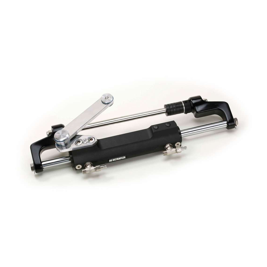
450 Kg - 992 lbs (@70 bar) Inside diameter 35 mm - 1.37" Stroke 198 mm - 7.79" OL150 Ultraflex 544 mm (21.43") STANDARD VERSION (STARBOARD) PORT VERSION CAUTION *The cylinder output force is a theoretical force with a system pressure of 105 bar. This force does not correspond to the one normally used by the system but it represents the limiting conditions of use. -
Page 10: Transport
ULTRAFLEX Installation and Maintenance Manual 2 TRANSPORT 2.1 General warnings The product weight with its packaging is 8kg (18 pounds) and so it can be handled manually. WARNING The staff in charge of handling must operate with protective gloves and safety shoes. -
Page 11: Minimum Transom Requirements
ULTRAFLEX Installation and Maintenance Manual 3 INSTALLATION 3.1 Minimum transom requirements The following picture shows the minimum splash well dimensions. These dimensions must be respected in order to prevent the cylinder from being damaged when the outboard engine is completely tilted upwards. -
Page 12: Standard (Starboard)Cylinder Installation
ULTRAFLEX Installation and Maintenance Manual 3.3 Standard (starboard) cylinder installation After removing the protective caps of the CAUTION fittings, manually center the rod (1) on the cylinder During the installation phases use only stainless body (2). steel tools to avoid the corrosion of the metal parts. - Page 13 ULTRAFLEX Installation and Maintenance Manual Fit the set screw (10) on the adjustment collar 10 With reference to the' "Application Guide" (11) and screw it to the right side of the tilt tube choose the spacers for the tilt tube rod.
- Page 14 ULTRAFLEX Installation and Maintenance Manual 17 Position the lock washers (15) and lock screw 16 Insert the washers (13) on the two ends of the (16) by using a 19mm wrench with a torque of 70[Nm] tilt tube rod, grease the nut thread (14) with (52 [lb·...
-
Page 15: Hose Installation
ULTRAFLEX Installation and Maintenance Manual 3.4 Hose installation The two fittings mounted on the cylinder body are already oriented and are ready to be used. If for practical reasons the orientation must be changed, do as follows: 1. loose the locknut (A) by using a 11/16"wrench;... -
Page 16: Type Of Installation
ULTRAFLEX Installation and Maintenance Manual 3.5 Type of installation The UC128-TS hydraulic cylinder for outboard engines can be installed with different configurations according to the number and the type of engines used with a single or dual steering system. The possible configurations... -
Page 17: Filling And Purging
- Mobil DTE 11M NOTICE ULTRAFLEX will not be able to ensure the compatibility of the above mentioned oils with OL150 if the oil manufacturers vary their formulation; in particular, it will not be able to ensure its compliance with standard ISO 10592 concerning hydraulic steering systems. -
Page 18: Positioning Of The Oil Bottle
ULTRAFLEX Installation and Maintenance Manual 3.6.1 Positioning of the oil bottle To carry out this operation, it is necessary to use the oil filling kit (1 needle, 1 transparent oil bottle pipe, 1 pipe connection and 1 spout for the oil bottle). This kit is NOT supplied. -
Page 19: Single Steering Station/Dual Cylinder
ULTRAFLEX Installation and Maintenance Manual - Open the other bleed valve and move purged oil tank to the other side. Holding the cylinder body in this position, turn the steering wheel as shown in picture 4, until oil without air bubbles comes out of the bleed valve. -
Page 20: Dual Steering Station/Dual Cylinder
ULTRAFLEX Installation and Maintenance Manual WARNING For the additional steering station (lower) tank use only the silver non-vent plug (supplied with the "kit OB- 2S"). For the main steering station (upper) tank use only the black vent plug. - Repeat the procedure at least 3 times to ensure the absence of air in the system. -
Page 21: Safety Warnings During Use And Installation
4.1 Safety warnings during use and installation RESPECT STRICTLY the following safety rules: ULTRAFLEX declines all responsibility in case the user does not follow these rules and it is not responsible for negligence during the use of the system. DANGER DO NOT PUT HANDS BETWEEN THE MOVING PARTS. -
Page 22: Ordinary Maintenance
WARNING If worn heads are not replaced, the cylinder cannot work properly, thus jeopardizing the safety of the user. ULTRAFLEX supplies a proper kit containing the components to be used for replacement. NOTICE The kit is supplied with the replacement instructions. -
Page 23: Troubleshooting
WARNING Whenever the following checks need the removal and/or disassembly of the steering system components, such work must be carried by specialized staff. ULTRAFLEX offers general information only and is not responsible for any consequences resulting from incorrect disassembly. PROBLEM... - Page 24 ULTRAFLEX Installation and Maintenance Manual The steering system is • The steering wheel is too • Replace the steering wheel with a bigger one. easy to turn at the dock but small. becomes hard to turn when the boat is in motion.
-
Page 25: Dismantling
ULTRAFLEX Installation and Maintenance Manual 6 DISMANTLING 6.1 Dismantling When for any reason, the steering system is put out of service, it is necessary to follow some rules in order to respect the environment. Sheaths, pipelines, plastic or non-metallic components must be disassembled and disposed of separately. - Page 26 ULTRAFLEX Installation and Maintenance Manual NOTES page 26 of 78 - HYDRAULIC CYLINDER FOR OUTBOARD ENGINE...
- Page 27 Manuale di installazione e manutenzione CILINDRO IDRAULICO PER MOTORI FUORIBORDO UC 128-TS SOCIO...
- Page 28 Gentile Cliente, La ringraziamo per aver scelto un prodotto ULTRAFLEX. ULTRAFLEX è da anni un punto di riferimento nei sistemi di guida nel settore della nautica da diporto e professionale. Da sempre la produzione ULTRAFLEX è sinonimo di grande affidabilità e sicurezza.
- Page 29 ULTRAFLEX Manuale di installazione e manutenzione INDICE GENERALE INDICE DELLE REVISIONI DEL DOCUMENTO..................30 USO DEL MANUALE E SIMBOLOGIA IMPIEGATA..................31 LETTERA INFORMATIVA..........................32 GARANZIA..........................32 SEZIONE 1 - DESCRIZIONE DEL PRODOTTO FUNZIONAMENTO DI UN SISTEMA DI GUIDA IDRAULICO................33 AVVERTENZE PER IL CORRETTO UTILIZZO DEL PRODOTTO..............33 CONFIGURAZIONI.........................34...
-
Page 30: Indice Delle Revisioni Del Documento
ULTRAFLEX Manuale di installazione e manutenzione INDICE DELLE REVISIONI DEL DOCUMENTO Rev. Data Descrizione della revisione 20/02/2006 Prima realizzazione 27/07/2018 Buova versione con testate smontabili pag. 30 di 78 - CILINDRO IDRAULICO PER MOTORE FUORIBORDO... -
Page 31: Uso Del Manuale E Simbologia Impiegata
ULTRAFLEX Manuale di installazione e manutenzione USO DEL MANUALE E SIMBOLOGIA IMPIEGATA Il MANUALE DI INSTALLAZIONE E MANUTENZIONE è il documento che accompagna il prodotto dal momento della sua vendita fino alla sua sostituzione e smaltimento. Risulta cioè essere parte integrante dello stesso. -
Page 32: Lettera Informativa
GARANZIA ULTRAFLEX garantisce che i suoi prodotti sono costruiti a regola d'arte e che sono privi di difetti di fabbricazione e di materiali. Questa garanzia è valida per un periodo di due anni decorrenti dalla data di fabbricazione dei prodotti ad eccezione dei casi in cui questi siano installati ed usati su barche da lavoro o comunque su barche ad utilizzo commerciale, nel qual caso la garanzia è... -
Page 33: Descrizione Del Prodotto
I sistemi idraulici di guida ULTRAFLEX sono progettati in conformità alla normativa UNI-EN-ISO 10592 ed alla A.B.Y.C. P21. I sistemi di guida ULTRAFLEX sono in grado di operare in un campo di temperatura ambiente compreso tra -18°C (0°F) e +77°C (+170°F), tutti i loro componenti sono stati realizzati specificatamente per l'ambiente marino, utilizzando materiali e processi di fabbricazione che offrono grande durata e sicurezza anche nelle condizioni più... -
Page 34: Configurazioni
Con DOPPIO CILINDRO (starboard + port) NOTA Sono disponibili a richiesta applicazioni con triplo motore fuoribordo. Per informazioni dettagliate si prega di contattare il Servizio Assistenza ULTRAFLEX. PERICOLO In caso di installazioni con doppio motore è obbligatorio utilizzare una barra di accoppiamento. -
Page 35: Descrizione Del Cilindro Uc128-Ts
Diametro interno 35 mm - 1.37" Corsa 198 mm - 7.79" Olio OL150 Ultraflex 544 mm (21.43") VERSIONE STANDARD (STARBOARD) VERSIONE PORT ATTENZIONE * La spinta del cilindro indicata è una spinta teorica calcolata con una pressione di sistema di 70 bar. Tale spinta non corrisponde a quella di normale utillzzo del sistema ma rappresenta la condizione limite di utilizzo. -
Page 36: Avvertenze Generali
ULTRAFLEX Manuale di installazione e manutenzione 2 TRASPORTO 2.1 Avvertenze generali Il peso del prodotto con il suo imballo è 8Kg (18 pounds) e quindi la sua movimentazione può essere effettuata manualmente. AVVERTENZA Il personale addetto alla manipolazione del carico deve operare con guanti protettivi e scarpe anti infortunistiche. -
Page 37: Requisiti Minimi Dello Specchio Di Poppa
ULTRAFLEX Manuale di installazione e manutenzione 3 INSTALLAZIONE 3.1 Requisiti minimi dello specchio di poppa Di seguito sono indicate le dimensioni minime del pozzetto. Queste dimensioni sono richieste per prevenire danni al cilindro, quando il motore fuoribordo è completamente ruotato verso l'alto (Tilt). Inoltre sono rappresen- tate le dimensioni dello specchio di poppa, per consentire l'installazione e il corretto funzionamento del cilindro di guida del motore. -
Page 38: Installazione Del Cilindro Standard (Starboard)
ULTRAFLEX Manuale di installazione e manutenzione 3.3 Installazione del cilindro standard (starboard) Dopo aver rimosso i tappi di protezione dei ATTENZIONE raccordi, centrare manualmente lo stelo (1) rispetto Durante le fasi di installazione utilizzare esclusivamente utensili in al corpo del cilindro (2). - Page 39 ULTRAFLEX Manuale di installazione e manutenzione Imboccare il grano (10) sulla ghiera di regolazione 10 Facendo riferimento all' "Application Guide" individua- fine (11) e avvitare quest'ultima sul lato destro del re i distanziali necessari da posizionare sull'asta motore. tubo motore fino a portarla in battuta, anche in caso di applicazioni port.
- Page 40 ULTRAFLEX Manuale di installazione e manutenzione 16 Inserire le rondelle (13) sulle due estremità del- 17 Posizionare le rondelle di sicurezza (15) e avvitare la vite di bloccaggio (16) con una chiave da 19mm serrandola l'asta del tubo motore, ingrassare la filettatura dei con una coppia di 70[Nm] (52 [lb·...
-
Page 41: Installazione Tubi
ULTRAFLEX Manuale di installazione e manutenzione 3.4 Installazione tubi I due raccordi montati sul corpo del cilindro sono già orientati e pronti per essere utilizzati. Se per motivi pratici dovesse sorgere la necessità di modificarne l'orientamento procedere come segue: 1. allentare il dado di bloccaggio (A) con una chiave da 11/16";... -
Page 42: Tipi Di Installazione
ULTRAFLEX Manuale di installazione e manutenzione 3.5 Tipi di installazione Il cilindro idraulico per motori fuoribordo modello UC128-TS può essere installato in diverse configurazioni in funzione del numero e del tipo di motori utilizzati in accoppiamento ad un sistema di guida a singola o doppia stazione. -
Page 43: Riempimento E Spurgo
- Mobil DTE 11M NOTA ULTRAFLEX non potrà garantire la compatibilità degli oli citati con OL150 in caso di variazione alle formulazioni da parte dei produttori degli oli stessi, in particolare non potrà garantirne la rispondenza alla ISO 10592 relativa ai sistemi di guida idraulici. Eventuali cali prestazionali e/o di durata non saranno in nessun caso imputabili ad ULTRAFLEX. -
Page 44: Posizionamento Della Bottiglia Dell'olio
ULTRAFLEX Manuale di installazione e manutenzione 3.6.1 Posizionamento della bottiglia dell'olio Per effettuare questa operazione è necessario il kit di riempimento olio (1 spillo, 1 tubo bottiglia olio trasparente, 1 raccordo portatubo e 1 beccuccio per bottiglia olio) NON fornito in dotazione. -
Page 45: Stazione Di Guida Doppia/ Cilindro Singolo
ULTRAFLEX Manuale di installazione e manutenzione - Aprire l'altra valvola di spurgo e posizionare il contenitore di recupero del- l'olio dall'altra parte. Trattenendo il corpo del cilindro in questa posizione, ruotare lentamente il volante come indicato in figura 4, fino a che dalla val- vola di spurgo non defluirà... -
Page 46: Raccomandazione Generale
ULTRAFLEX Manuale di installazione e manutenzione AVVERTENZA Per il serbatoio della stazione di guida supplementare (inferiore) utilizzare esclusivamente il tappo senza foro di sfiato di colore argento (fornito con il "kit OB-2S"). Per il serbatoio della stazione di guida primaria (superiore) utilizzare esclusivamente il tappo con il foro di sfiato di colore nero. -
Page 47: Avvertenze Di Sicurezza
RISPETTATE TASSATIVAMENTE le precauzioni ed i criteri di sicurezza indicati qui di seguito. ULTRAFLEX. declina ogni responsabilità nel caso in cui l'utilizzatore non li osservi, così come non è respon- sabile per qualsiasi tipo di negligenza che venga commessa durante l'utilizzo del sistema. -
Page 48: Manutenzione Ordinaria
La mancata sostituzione delle testate usurate comporta il malfunzionamento del cilindro generando pericolo per l'utilizzatore. ULTRAFLEX fornisce un apposito kit contenente i componenti necessari per la sostituzione. NOTA Con il kit vengono fornite le istruzioni relative alla corretta procedura di sostituzione. -
Page 49: Ricerca Guasti
Ogni qualvolta i seguenti controlli richiedano la rimozione e/o smontaggio dei componenti del sistema di guida, richiedere l'intervento di personale qualificato. ULTRAFLEX offre le indicazioni generali e non può essere ritenuta responsabile per eventuali informazioni e conseguenze derivanti da un errato smontaggio. - Page 50 ULTRAFLEX Manuale di installazione e manutenzione La timoneria si manovra • Il volante di guida è troppo pic- • Sostituire il volante di guida con uno più grande. agevolmente in banchina, colo. ma diventa rigida quando AVVERTENZA l'imbarcazione è in movi- Solo entro le dimensioni massime consen- mento.
-
Page 51: Smantellamento
ULTRAFLEX Manuale di installazione e manutenzione 6 SMANTELLAMENTO 6.1 Smantellamento Qualora si intenda, per qualsiasi motivo, mettere fuori servizio il sistema di guida, è necessario osservare alcune regole fondamentali atte a salvaguardare l’ambiente. Guaine, condotti flessibili, componenti di materiale plastico o comunque non metallico, dovranno essere smon- tati e smaltiti separatamente. - Page 52 ULTRAFLEX Manuale di installazione e manutenzione NOTE pag. 52 di 78 - CILINDRO IDRAULICO PER MOTORE FUORIBORDO...
-
Page 53: Verin Hydraulique Pour Moteurs Hors-Bord
Manuel d'installation et d'entretien VERIN HYDRAULIQUE POUR MOTEURS HORS-BORD UC 128-TS ASSOCIE... - Page 54 (voir annexe "Application Spare Parts"). Les Systèmes de Gestion de la Qualité ULTRAFLEX et UFLEX sont certifiés par le Det Norske Veritas - Germanischer Lloyd (DNV-GL), en conformité avec la Norme UNI EN ISO 9001:2015.
-
Page 55: Important
ULTRAFLEX Manuel d'installation et d'entretien INDEX GENERAL INDEX DES REVISIONS DU DOCUMENT....................56 EMPLOI DU MANUEL ET SYMBOLES UTILISES....................57 LETTRE D'INFORMATION...........................58 GARANTIE............................58 SECTION 1 - DESCRIPTION DU PRODUIT FONCTIONNEMENT D'UN SYSTEME DE GOUVERNEMENT HYDRAULIQUE..........59 AVERTISSEMENTS POUR L'EMPLOI CORRECT DU PRODUIT..............59 CONFIGURATIONS.........................60 DESCRIPTION DU VERIN UC128-TS......................61... -
Page 56: Index Des Revisions Du Document
ULTRAFLEX Manuel d'installation et d'entretien INDEX DES REVISIONS DU DOCUMENT Rév. Date Description de la révision 20/02/2006 Première réalisation 27/07/2018 Nouvelle version avec têtes amovibles page 56 de 78 - VERIN HYDRAULIQUE POUR MOTEUR HORS-BORD... -
Page 57: Emploi Du Manuel Et Symboles Utilises
ULTRAFLEX Manuel d'installation et d'entretien EMPLOI DU MANUEL ET SYMBOLES UTILISES Le MANUEL D'INSTALLATION ET D'ENTRETIEN est le document qui accompagne le produit de sa vente jusqu'à son remplacement et sa démolition. C'est donc une partie fondamentale du manuel lui-même. -
Page 58: Lettre D'information
GARANTIE La Société ULTRAFLEX garantit que ses produits sont fabriqués à règles d'art et qu'ils n'ont aucun défaut de fabrication et de matériels. Cette garantie a une validité de deux années à partir de la date de fabrication des produits à l'exception des cas où... -
Page 59: Description Du Produit
équlibrés demandent le même nombre de tours du volant pour déplacer le gouvernail du centre au fin de course dans les deux sens opposés. Un système de gouvernement équilibré et facile à manoeuvrer demande un choix correct du type de pompe à accoupler au vérin. ULTRAFLEX produit plusieurs modèles de pompes, dont les différences sont le débit (cm d'huile déplacés à... -
Page 60: Configurations
Avec VERIN DOUBLE (starboard + port) NOTE Sur demande on peut obtenir des applications avec moteur hors-bord triple. Pour toute information détaillée contacter le Service d'Assistance ULTRAFLEX. DANGER En cas d'installations avec moteur double l'emploi d'une barre d'accouplement est obligatoire. -
Page 61: Description Du Verin Uc128-Ts
Diamètre intérieur 35 mm - 1.37" Course 198 mm - 7.79" Huile OL150 Ultraflex 544 mm (21.43") VERSION STANDARD (STARBOARD) VERSION PORT ATTENTION *La poussée du vérin indiquée est une poussée théorique calculée avec une pression de système de 70bar. Cette poussée ne correspond pas à... -
Page 62: Avertissements Generaux
ULTRAFLEX Manuel d'installation et d'entretien 2 TRANSPORT 2.1 Avertissements généraux Le poids du produit avec son emballage est 8Kg (18 livres), il peut donc être manutentionné manuellement. AVERTISSEMENT Le personnel chargé de la manipulation de l'installation doit porter des gants de protection et des chaussures de sécurité. -
Page 63: Prescriptions Minimales Arcasse
ULTRAFLEX Manuel d'installation et d'entretien 3 INSTALLATION 3.1 Prescriptions minimales arcasse Les dimensions minimum du cockpit sont indiquées ci-dessous. Elles sont nécessaires pour éviter d'endommager le vérin, quand le moteur hors-bord est complètement tourné vers le haut (Tilt). On indique aussi les dimensions du tableau arrière, pour permettre l'installation et le fonctionnement correct du vérin... -
Page 64: Installation Du Verin Standard (Starboard)
ULTRAFLEX Manuel d'installation et d'entretien 3.3 Installation du vérin standard (starboard) Après avoir enlevé les bouchons de protection ATTENTION des raccords, centrer manuellement la tige (1) par Pendant phases rapport au corps du vérin (2). d'installation utiliser exclusivement des outils en acier inox afin d'éviter... - Page 65 ULTRAFLEX Manuel d'installation et d'entretien 10 En se référant à l' "Application Guide" Positionner la vis sans tête (10) sur la bague identifier les entretoises à positionner sur la tige d'espacement (11) et visser cette dernière sur le du tube de guidage.
- Page 66 ULTRAFLEX Manuel d'installation et d'entretien 17 Positionner les rondelles de sûreté (15) et 16 Insérer les rondelles (13) dans les deux visser la vis de blocage (16) à l'aide d'une clé de extrémités de la tige du tube de guidage graisser 19mm avec couple de serrage de 70[Nm] (52 [lb·...
-
Page 67: Installation Tuyaux
ULTRAFLEX Manuel d'installation et d'entretien 3.4 Installation tuyaux Les deux raccords assemblés sur le corps du vérin sont déjà orientés et prêts pour être utilisés. Pour en modifier l'orientation procéder de la façon suivante: 1. desserrer l'écrou de blocage (A) à l'aide d'une clé de 11/16";... -
Page 68: Types D'installation
ULTRAFLEX Manuel d'installation et d'entretien 3.5 Types d'installation Le vérin hydraulique pour moteurs hors-bord modèle UC128-TS peut être installé dans plusieurs configurations en fonction du nombre et du type de moteurs utilisés avec un système de gouvernement unique ou double. Les configurations possibles sont indiquées ci-dessous: ATTENTION Toujours connecter les tuyaux avec attention comme montré... -
Page 69: Remplissage Et Purge
L'huile hydraulique OL150 est spécifiquement formulée pour ULTRAFLEX afin de maintenir le plus longtemps possible pendant le temps le haut niveau de qualité et de performance des produits ULTRAFLEX. Sa formule particulière "Sans Zinc" favorise la protection contre l’oxydation marine. Le mélange particulier des composants antiusures et stabilisants, dont OL150 est composé, permettent d’obtenir un résultat optimal... -
Page 70: Positionnement De La Bouteille De L'huile
ULTRAFLEX Manuel d'installation et d'entretien 3.6.1 Positionnement de la bouteille de l'huile Pour effectuer cette opération il faut avoir le kit de remplissage huile (1 pointeau, 1 tuyau transparent, 1 raccord porte tuyau et 1 bec pour la bouteille huile) NON fourni. -
Page 71: Poste De Gouvernement Unique/Verin Double
ULTRAFLEX Manuel d'installation et d'entretien - Ouvrir l'autre soupape de purge et positionner le bac de récupération de l'huile de l'autre côté. Tenir le corps du vérin dans cette position et tourner lentement le volant comme indiqué dans la figure 4, jusqu'à ce que de l'huile sans bulles sort de la soupape de purge. -
Page 72: Poste De Gouvernement Double/Verin Double
ULTRAFLEX Manuel d'installation et d'entretien AVERTISSEMENT Pour le réservoir du poste de gouvernement supplémentaire (inférieur) utiliser exclusivement le bouchon sans trou d'évent argent (fourni avec le "kit OB-2S"). Pour le réservoir du poste de gouvernement principal (supérieur) utiliser exclusivement le bouchon avec le trou d'évent couleur noir. -
Page 73: Avertissements De Securite
RESPECTER RIGOUREUSEMENT les précautions et les critères de sécurité indiqués ci-dessous. La Société ULTRAFLEX. décline toute responsabilité au cas pù l'usager ne les respecterait pas; elle n'est pas non plus responsable pour tout type de négligence commise pendant l'emploi du système. -
Page 74: Entretien Ordinaire
Si les têtes usées ne sont pas remplacées, le cylindre ne fonctionne pas correctement mettant en danger l’utilisateur. ULTRAFLEX fournit un kit spécial contenant les composants nécessaires pour le remplacement. NOTE Le kit est équipé avec les instructions relatives à la procédure correcte de remplacement. -
Page 75: Recherche Des Pannes
Toutes les fois que les contrôles suivants nécessitent du désasemblage des composants du système de gouvernement, il faut demander l'intervention du personnel qualifié. La Société ULTRAFLEX offres des indications générales et décline donc toute responsabilité pour les informations et les conséquences dérivant d'un désassemblage incorrect. - Page 76 ULTRAFLEX Manuel d'installation et d'entretien PROBLEME CAUSE POSSIBLE INTERVENTION direction • Le volant est trop petit. • Remplacer le volant avec un volant plus grand. manoeuvre facilement dans le quai, mais elle est AVERTISSEMENT rigide quand le bateau Seulement dans les dimensions maximum est en mouvement.
-
Page 77: Demolition
ULTRAFLEX Manuel d'installation et d'entretien 6 DEMOLITION 6.1 Démolition Si la machine doit être mise hors service pour quelques raisons que ce soit, les règles fondamentales suivantes doivent être observées pour la protection de l'environnement. aines, conduits flexibles, composants de matériel plastique ou non métalliques, devront être désassemblés et éliminés séparement. - Page 78 ULTRAFLEX Manuel d'installation et d'entretien NOTES page 78 de 78 - VERIN HYDRAULIQUE POUR MOTEUR HORS-BORD...
- Page 80 ULTRAFLEX S.p.A. 16015 Casella (Genova) Italia - Via Crose, 2...