Chapitres
Table des Matières
Dépannage

Manuels Connexes pour Ultraflex UC 95-OBF


Sommaire des Matières pour Ultraflex UC 95-OBF
- Page 1 Installation and Maintenance manual HYDRAULIC CYLINDER FOR OUTBOARD ENGINES UC 95-OBF ULTRAFLEX page 2 pag. 27 page 53 PARTNER (Dr./Dis./Des. n° 35204/c - 10/07/2020)
- Page 2 ULTRAFLEX production is since ever synonimous of reliability and safety. All ULTRAFLEX products are designed and manufactured to ensure the best performance. To ensure your safety and to maintain a high quality level, ULTRAFLEX products are guaranteed only if they are used with original spare parts.
-
Page 3: Table Des Matières
ULTRAFLEX Installation and Maintenance Manual TABLE OF CONTENTS ���������������������������������������������������������������������������������������������������������������������������������� DOCUMENT REVISIONS ��������������������������������������������������������������������������������������������������������������� MANUAL USE AND SYMBOLS USED ���������������������������������������������������������������������������������������������������������������������������������������������� INTRODUCTION ���������������������������������������������������������������������������������������������������������������������������������������������������� WARRANTY SECTION 1 - PRODUCT DESCRIPTION ��������������������������������������������������������������������������������������� HYDRAULIC STEERING SYSTEM OPERATION ������������������������������������������������������������������������������������ WARNINGS FOR THE CORRECT PRODUCT USE ������������������������������������������������������������������������������������������������������������������������������ CONFIGURATIONS ����������������������������������������������������������������������������������������������������... -
Page 4: Document Revisions
ULTRAFLEX Installation and Maintenance Manual DOCUMENT REVISIONS Rev. Rev. Date Date Revision description Revision description 10/07/2020 First edition page 4 of 79 - HYDRAULIC CYLINDER FOR OUTBOARD ENGINE... -
Page 5: Use Of The Manual And Symbols Used
ULTRAFLEX Installation and Maintenance Manual USE OF THE MANUAL AND SYMBOLS USED THE INSTALLATION AND MAINTENANCE MANUAL is the document accompanying the product from its sale to its replacement and discharge. The manual is an important part of the product itself. -
Page 6: Informative Letter
We remind you that only marked steering systems must be used on the boats marked We inform you that the ULTRAFLEX warranty is null if some ULTRAFLEX components are installed on a steering system together with products of other brands. -
Page 7: Product Description
A well balanced steering sys- tem needs a correct choice of the pump for the cylinder. ULTRAFLEX produces different pump models, which have different capacity (cm of oil moved each steering wheel turn) and for each type of installation. While choosing the pump it is important to consider the cylinder volume. -
Page 8: Configurations
Check the compatibility of the tie bar with the engines CAUTION Also in case of single engine applications with a horsepower which exceeds 175hp or 55 m.p.h., it is necessary to assemble the ULTRAFLEX UC 128-OBF or UC128-SVS cylinder. page 8 of 79 -... -
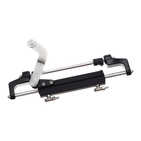
Page 9: Uc95-Obf Cylinder Description
354 Kg - 780 lbs (@70 bar) Inside diameter 30 mm - 1.18” Stroke 186 mm - 7.3” OL150 Ultraflex UC95-OBF/1 UC95-OBF/2 CAUTION * The cylinder thrust shown above is a theoretical value calculated considering a pressure system of 70 bar (1000 psi). -
Page 10: Transport
ULTRAFLEX Installation and Maintenance Manual 2 TRANSPORT 2.1 General warnings The product weight with its packaging is 8kg (18 pounds) and so it can be handled manually. WARNING The staff in charge of handling must operate with protective gloves and safety shoes. -
Page 11: Minimum Transom Requirements
ULTRAFLEX Installation and Maintenance Manual 3 INSTALLATION 3.1 Minimum transom requirements The following picture shows the minimum splash well dimensions. These dimensions must be respected in order to prevent the cylinder from being damaged when the outboard engine is completely tilted upwards. The picture shows also the minimum transom dimensions, needed for the installation and the correct operation of the engine steering cylinder. -
Page 12: Cylinder Installation
ULTRAFLEX Installation and Maintenance Manual 3.3 Cylinder installation Position the engine straight so that its arm is perpen- After removing the protective caps of the fittings, dicular to the transom. manually center the rod (1) on the cylinder body (2). - Page 13 ULTRAFLEX Installation and Maintenance Manual With reference to the' "Application Guide" choose Insert the right and left bull horns (11) by con- the spacers for the tilt tube rod. necting the rod and the tilt tube rod as shown in the picture.
- Page 14 ULTRAFLEX Installation and Maintenance Manual 17 Unscrew the adjustment collar (10) and bring 19 Tighten the set screw (8) on the adjustment collar it into contact with the stainless washer, until the (10) with a torque of 3[Nm] (2 [lb∙ft]).
-
Page 15: Hose Installation
ULTRAFLEX Installation and Maintenance Manual 3.4 Hose installation The two fittings mounted on the cylinder body are already oriented and are ready to be used. If for practical rea- sons the orientation must be changed, do as follows: 1. loose the stop nut (A) by using an 11/16" wrench;... -
Page 16: Type Of Installation
ULTRAFLEX Installation and Maintenance Manual 3.5 Type of installation The UC95-OBF hydraulic cylinder for outboard engines can be installed with a single or dual steering system. The possible configurations are: CAUTION Connect hoses as shown in the following pictures: SINGLE STATION / SINGLE CYLINDER: DUAL STATION / SINGLE CYLINDER: 1. -
Page 17: Filling And Purging
NOTICE ULTRAFLEX will not be able to ensure the compatibility of the above mentioned oils with OL150 if the oil manufac- turers vary their formulation; in particular, it will not be able to ensure its compliance with standard ISO 10592 concerning hydraulic steering systems. -
Page 18: Single Steering Station/ Single Cylinder
ULTRAFLEX Installation and Maintenance Manual WARNING oil bottle While replacing the oil bottle, during the filling process, close all the bleed valves on the cylinder/s. To bleed the system, check that oil is always present in the filling hose. If some air is in the system during the bleeding process, the whole bleeding spout process must be started again. -
Page 19: Dual Steering Station/ Single Cylinder
ULTRAFLEX Installation and Maintenance Manual - Open the other bleed valve and move purged oil tank to the other side. Holding the cylinder body in this position, turn the steering wheel as shown in picture 4, until oil without air bubbles comes out of the bleed valve. -
Page 20: General Recommendations
ULTRAFLEX Installation and Maintenance Manual 3.7 General recommendation WARNING It is very important to check the absence of air in the system before using the boat! We recommend trying to manually move the engine towards port and starboard, making sure that there is no movement of the cylinder body on the main cylinder shaft. -
Page 21: Safety Warnings During Use And Installation
4.1 Safety warnings during use and installation RESPECT STRICTLY the following safety rules: ULTRAFLEX declines all responsibility in case the user does not follow these rules and it is not responsible for negligence during the use of the system. DANGER DO NOT PUT HANDS BETWEEN THE MOVING PARTS. -
Page 22: Ordinary Maintenance
WARNING If worn heads are not replaced, the cylinder cannot work properly, thus jeopardizing the safety of the user. ULTRAFLEX supplies a proper kit containing the components to be used for replacement. NOTICE The kit is supplied with the replacement instructions. -
Page 23: Troubleshooting
WARNING Whenever the following checks need the removal and/or disassembly of the steering system components, such work must be carried by specialized staff. ULTRAFLEX offers general information only and is not responsible for any consequences resulting from incorrect disassembly. PROBLEM... - Page 24 ULTRAFLEX Installation and Maintenance Manual The steering system is easy to turn • The steering wheel is too small. • Replace the steering wheel with a at the dock but becomes hard to turn bigger one. when the boat is in motion.
-
Page 25: Dismantling
ULTRAFLEX Installation and Maintenance Manual 6 DISMANTLING 6.1 Dismantling When for any reason, the steering system is put out of service, it is necessary to follow some rules in order to respect the environment. Sheaths, pipelines, plastic or non-metallic components must be disassembled and disposed of separately. - Page 26 ULTRAFLEX Installation and Maintenance Manual NOTES page 26 of 79 - HYDRAULIC CYLINDER FOR OUTBOARD ENGINE...
- Page 27 Manuale di installazione e manutenzione CILINDRO IDRAULICO PER MOTORI FUORIBORDO UC 95-OBF ULTRAFLEX SOCIO...
- Page 28 Gentile Cliente, La ringraziamo per aver scelto un prodotto ULTRAFLEX. ULTRAFLEX è da anni un punto di riferimento nei sistemi di guida nel settore della nautica da diporto e profes- sionale. Da sempre la produzione ULTRAFLEX è sinonimo di grande affidabilità e sicurezza.
- Page 29 ULTRAFLEX Manuale di installazione e manutenzione INDICE GENERALE INDICE DELLE REVISIONI DEL DOCUMENTO........................30 USO DEL MANUALE E SIMBOLOGIA IMPIEGATA......................31 LETTERA INFORMATIVA ..............................32 GARANZIA ..................................32 SEZIONE 1 - DESCRIZIONE DEL PRODOTTO FUNZIONAMENTO DI UN SISTEMA DI GUIDA IDRAULICO ................33 AVVERTENZE PER IL CORRETTO UTILIZZO DEL PRODOTTO .................33 CONFIGURAZIONI ..............................34...
-
Page 30: Indice Delle Revisioni Del Documento
ULTRAFLEX Manuale di installazione e manutenzione INDICE DELLE REVISIONI DEL DOCUMENTO Rev. Rev. Data Data Descrizione della revisione Descrizione della revisione 10/07/2020 Prima realizzazione pag. 30 di 79 - CILINDRO IDRAULICO PER MOTORE FUORIBORDO... -
Page 31: Uso Del Manuale E Simbologia Impiegata
ULTRAFLEX Manuale di installazione e manutenzione USO DEL MANUALE E SIMBOLOGIA IMPIEGATA Il MANUALE DI INSTALLAZIONE E MANUTENZIONE è il documento che accompagna il prodotto dal momento della sua vendita fino alla sua sostituzione e smaltimento. Risulta cioè essere parte integrante dello stesso. -
Page 32: Lettera Informativa
GARANZIA ULTRAFLEX garantisce che i suoi prodotti sono costruiti a regola d'arte e che sono privi di difetti di fabbricazione e di materiali. Questa garanzia è valida per un periodo di due anni decorrenti dalla data di fabbricazione dei prodotti ad eccezione dei casi in cui questi siano installati ed usati su barche da lavoro o comunque su barche ad utilizzo commerciale, nel qual caso la garanzia è... -
Page 33: Descrizione Del Prodotto
II sistemi idraulici di guida ULTRAFLEX sono progettati in conformità alla normativa UNI-EN-ISO 10592 ed alla A.B.Y.C. P21. I sistemi di guida ULTRAFLEX sono in grado di operare in un campo di temperatura ambiente compreso tra -18°C (0°F) e +77°C (+170°F), tutti i loro componenti sono stati realizzati specificatamente per l'ambiente marino, utilizzando materiali e processi di fabbricazione che offrono grande durata e sicurezza anche nelle condizioni più... -
Page 34: Configurazioni
Verificare la compatibilità della barra di accoppiamento con i motori ATTENZIONE In caso di applicazioni anche con singolo motore la cui potenza ecceda i 175 hp o 55 m.p.h. è obbligatorio montare il cilindro ULTRAFLEX UC 128-OBF o UC 128-SVS. pag. 34 di 79 -... -
Page 35: Descrizione Del Cilindro Uc95-Obf
354 Kg - 780 lbs (@70 bar) Diametro interno 30 mm - 1.18” Corsa 186 mm - 7.3” Olio OL150 Ultraflex UC95-OBF/1 UC95-OBF/2 ATTENZIONE * La spinta del cilindro indicata è una spinta teorica cal- colata con una pressione di sistema di 70 bar (1000 psi). -
Page 36: Avvertenze Generali
ULTRAFLEX Manuale di installazione e manutenzione 2 TRASPORTO 2.1 Avvertenze generali Il peso del prodotto con il suo imballo è 8Kg (18 pounds) e quindi la sua movimentazione può essere effettuata manualmente. AVVERTENZA Il personale addetto alla manipolazione del carico deve operare con guanti protettivi e scarpe anti infortunistiche. -
Page 37: Requisiti Minimi Dello Specchio Di Poppa
ULTRAFLEX Manuale di installazione e manutenzione 3 INSTALLAZIONE 3.1 Requisiti minimi dello specchio di poppa Di seguito sono indicate le dimensioni minime del pozzetto. Queste dimensioni sono richieste per prevenire danni al cilindro, quando il motore fuoribordo è completamente ruotato verso l'alto (Tilt). Inoltre sono rappresentate le dimensioni dello specchio di poppa, per consentire l'installazione e il corretto funzionamento del cilindro di guida del motore. -
Page 38: Installazione Del Cilindro Standard (Starboard)
ULTRAFLEX Manuale di installazione e manutenzione 3.3 Installazione del cilindro Posizionare il motore dritto in modo che il suo brac- Dopo aver rimosso i tappi di protezione dei rac- cetto risulti perpendicolare allo specchio di poppa. cordi, centrare manualmente lo stelo (1) rispetto al corpo del cilindro (2). - Page 39 ULTRAFLEX Manuale di installazione e manutenzione Facendo riferimento all' "Application Guide" individuare Inserire le due staffe destra e sinistra (bullhorns) i distanziali necessari da posizionare sull'asta motore. (11) collegando stelo ed asta motore come indicato in figura. STRETTO LARGO MEDIO...
- Page 40 ULTRAFLEX Manuale di installazione e manutenzione 17 Svitare manualmente la ghiera di regolazione 19 Serrare la vite (8) della ghiera di regolazione fine fine (10) portandola in battuta sulla rondella in inox, ∙ (10) con una coppia di serraggio di 3[Nm] (2 [lb ft]).
-
Page 41: Installazione Tubi
ULTRAFLEX Manuale di installazione e manutenzione 3.4 Installazione tubi I due raccordi montati sul corpo del cilindro sono già orientati e pronti per essere utilizzati. Se per motivi pratici dovesse sorgere la necessità di modificarne l'orientamento rispettare quanto indicato di seguito. -
Page 42: Tipi Di Installazione
ULTRAFLEX Manuale di installazione e manutenzione 3.5 Tipi di installazione Il cilindro idraulico per motori fuoribordo modello UC95-OBF può essere installato in accoppiamento ad un sistema di guida a singola o doppia stazione. Le configurazioni possibili sono: ATTENZIONE Eseguire sempre con attenzione l'esatto collegamento dei tubi come rappresentato dalle seguenti illustrazioni. -
Page 43: Riempimento E Spurgo
- Mobil DTE 11M NOTA ULTRAFLEX non potrà garantire la compatibilità degli oli citati con OL150 in caso di variazione alle formulazioni da parte dei produttori degli oli stessi, in particolare non potrà garantirne la rispondenza alla ISO 10592 relativa ai sistemi di guida idraulici. -
Page 44: Stazione Di Guida Singola / Cilindro Singolo
ULTRAFLEX Manuale di installazione e manutenzione spillo AVVERTENZA bottiglia olio Al momento della sostituzione delle bottiglie d'olio durante il processo di riempimen- to, chiudere tutte le valvole di spurgo sui raccordi a "T" del cilindro/i. Per spurgare l'impianto, verificare che nel tubo flessibile di riempimento sia sempre presente... -
Page 45: Stazione Di Guida Doppia/ Cilindro Singolo
ULTRAFLEX Manuale di installazione e manutenzione Aprire l'altra valvola di spurgo e posizionare il contenitore di recupero dell'olio dall'altra parte. Trattenendo il corpo del cilindro in questa posizione, ruotare lentamente il volante come indicato in figura 4, fino a che dalla valvola di spurgo non defluirà... -
Page 46: Raccomandazione Generale
ULTRAFLEX Manuale di installazione e manutenzione 3.7 Raccomandazione generale AVVERTENZA È molto importante verificare che l'aria sia stata completamente spurgata dall'impianto prima di utilizzare la barca! Si consiglia di tentare di spostare manualmente il / i motore/i verso babordo e tribordo, prestando attenzione a qualsiasi movimento del corpo del cilindro sul suo stelo. -
Page 47: Avvertenze Di Sicurezza
RISPETTATE TASSATIVAMENTE le precauzioni ed i criteri di sicurezza indicati qui di seguito. ULTRAFLEX. declina ogni responsabilità nel caso in cui l'utilizzatore non li osservi, così come non è responsabile per qualsiasi tipo di negligenza che venga commessa durante l'utilizzo del sistema. -
Page 48: Manutenzione Ordinaria
La mancata sostituzione delle testate usurate comporta il malfunzionamento del cilindro generando pericolo per l'utilizzatore. ULTRAFLEX fornisce un apposito kit contenente i componenti necessari per la sostituzione. NOTA Con il kit vengono fornite le istruzioni relative alla corretta procedura di sostituzione. -
Page 49: Ricerca Guasti
Ogni qualvolta i seguenti controlli richiedano la rimozione e/o smontaggio dei componenti del sistema di guida, richiedere l'intervento di personale qualificato. ULTRAFLEX offre le indicazioni generali e non può essere ritenuta responsabile per eventuali informazioni e conseguenze derivanti da un errato smontaggio. - Page 50 ULTRAFLEX Manuale di installazione e manutenzione La timoneria si manovra agevol- • Il volante di guida è troppo • Sostituire il volante di guida con mente in banchina, ma diventa piccolo. uno più grande. rigida quando l'imbarcazione è in AVVERTENZA movimento.
-
Page 51: Smantellamento
ULTRAFLEX Manuale di installazione e manutenzione 6 SMANTELLAMENTO 6.1 Smantellamento Qualora si intenda, per qualsiasi motivo, mettere fuori servizio il sistema di guida, è necessario osservare alcune regole fondamentali atte a salvaguardare l’ambiente. Guaine, condotti flessibili, componenti di materiale plastico o comunque non metallico, dovranno essere smontati e smaltiti separatamente. - Page 52 ULTRAFLEX Manuale di installazione e manutenzione NOTE pag. 52 di 79 - CILINDRO IDRAULICO PER MOTORE FUORIBORDO...
- Page 53 Manuel d’installation et d’entretien VERIN HYDRAULIQUE POUR MOTEURS HORS-BORD UC 95-OBF ULTRAFLEX ASSOCIE...
- Page 54 Vérifier la conformité des produits aux prescriptions de la directive 2013/53/EU. "ULTRAFLEX avec plus de 85 années d’expérience dans le domaine nautique, est aujourd’hui une industrie de pointe sur échelle mondiale dans la production de systèmes de gouvernement mécaniques, hydrauliques, électroniques, boîtes de commande et volants pour bateaux moteur pour la plaisance, la pêche ou le travail...
- Page 55 ULTRAFLEX Manuel d’installation et d’entretien INDEX GENERAL INDEX DES REVISIONS DU DOCUMENT .........................56 EMPLOI DU MANUEL ET SYMBOLES UTILISES ......................57 LETTRE D'INFORMATION ..............................57 GARANTIE ..................................58 SECTION 1 - DESCRIPTION DU PRODUIT FONCTIONNEMENT D'UN SYSTEME DE GOUVERNEMENT HYDRAULIQUE ..........59 AVERTISSEMENTS POUR L'EMPLOI CORRECT DU PRODUIT .................59 CONFIGURATIONS ...............................60...
-
Page 56: Index Des Revisions Du Document
ULTRAFLEX Manuel d’installation et d’entretien INDEX DES REVISIONS DU DOCUMENT Rév. Rév. Date Date Description de la révision Description de la révision 10/07/2020 Première réalisation page 56 de 79 - VERIN HYDRAULIQUE POUR MOTEUR HORS-BORD... -
Page 57: Emploi Du Manuel Et Symboles Utilises
ULTRAFLEX Manuel d’installation et d’entretien EMPLOI DU MANUEL ET SYMBOLES UTILISES Le MANUEL D’INSTALLATION ET D’ENTRETIEN est le document qui accompagne le produit de sa vente jusqu’à son remplacement et sa démolition. C’est donc une partie fondamentale du manuel lui-même. -
Page 58: Lettre D'information
GARANTIE La Société ULTRAFLEX garantit que ses produits sont fabriqués à règles d’art et qu’ils n’ont aucun défaut de fabrication et de matériels. Cette garantie a une validité de deux années à partir de la date de fabrication des produits à... -
Page 59: Description Du Produit
Un système de gouvernement équilibré et facile à manoeuvrer demande un choix correct du type de pompe à accoupler au vérin. ULTRAFLEX produit plusieurs modèles de pompes, dont les différences sont le débit (cm d'huile déplacés à... -
Page 60: Configurations
Vérifier la compatibilité de la barre d'accouplement avec les moteurs ATTENTION En cas d'applications même avec moteur unique dont la puissance dépasse les 175 hp ou 55 m.p.h., il est obli- gatoire d'assembler le vérin Ultraflex UC 128-OBF ou UC 128-SVS. page 60 de 79 -... -
Page 61: Description Du Verin Uc95-Obf
354 Kg - 780 lbs (@70 bar) Diamètre intérieur 30 mm - 1.18” Course 186 mm - 7.3” Huile OL150 Ultraflex UC95-OBF/1 UC95-OBF/2 ATTENTION * La poussée du vérin indiquée est une poussée théorique calculée avec une pression de système de 70 bar (1000 psi). -
Page 62: Avertissements Generaux
ULTRAFLEX Manuel d’installation et d’entretien 2 TRANSPORT 2.1 Avertissements généraux Le poids du produit avec son emballage est 8Kg (18 livres), il peut donc être manutentionné manuellement. AVERTISSEMENT Le personnel chargé de la manipulation de l'installation doit porter des gants de protection et des chaussures de sécurité. -
Page 63: Prescriptions Minimales Arcasse
ULTRAFLEX Manuel d’installation et d’entretien 3 INSTALLATION 3.1 Prescriptions minimales arcasse Les dimensions minimum du cockpit sont indiquées ci-dessous. Elles sont nécessaires pour éviter d'endommager le vérin, quand le moteur hors-bord est complètement tourné vers le haut (Tilt). On indique aussi les dimensions du tableau arrière, pour permettre l'installation et le fonctionnement correct du vérin de guidage du moteur. -
Page 64: Installation Du Vérin
ULTRAFLEX Manuel d’installation et d’entretien 3.3 Installation du vérin Positionner le moteur droit de sorte que son bras Après avoir enlevé les bouchons de protection soit perpendiculaire à l'arcasse. des raccords, centrer manuellement la tige (1) par rapport au corps du vérin (2). - Page 65 ULTRAFLEX Manuel d’installation et d’entretien En se référant à l' "Application Guide" identifier les entre- Insérer les deux étriers droit et gauche (bull- toises à positionner sur la tige du tube de guidage. horns) (11) en connectant la tige et la tige du tube de guidage comme indiqué...
- Page 66 ULTRAFLEX Manuel d’installation et d’entretien 17 Dévisser manuellement la bague d'espacement 19 Serrer la vis sans tête (8) de la bague d'espa- (10) et la faire entrer en contact avec la rondelle en cement (10) avec couple de serrage de 3 [Nm] (2 inox, jusqu'à...
-
Page 67: Installation Tuyaux
ULTRAFLEX Manuel d’installation et d’entretien 3.4 Installation tuyaux Les deux raccords assemblés sur le corps du vérin sont déjà orientés et prêts pour être utilisés. Pour en modifier l'orientation procéder de la façon suivante: 1. desserrer l'écrou de blocage (A) à l'aide d'une clé de 11/16";... -
Page 68: Types D'installation
ULTRAFLEX Manuel d’installation et d’entretien 3.5 Types d'installation Le vérin hydraulique pour moteurs hors-bord modèle UC95-OBF peut être installé avec un système de gouver- nement à poste unique ou double. Les configurations possibles sont indiquées ci-dessous: ATTENTION Toujours connecter les tuyaux avec attention comme montré dans les dessins ci-dessous. -
Page 69: Remplissage Et Purge
L'huile hydraulique OL150 est spécifiquement formulée pour ULTRAFLEX afin de maintenir le plus longtemps possible pendant le temps le haut niveau de qualité et de performance des produits ULTRAFLEX. Sa formule par- ticulière "Sans Zinc" favorise la protection contre l’oxydation marine. Le mélange particulier des composants antiusures et stabilisants, dont OL150 est composé, permettent d’obtenir un résultat optimal en termes de durée... -
Page 70: Poste De Gouvernement Unique/ Vérin Unique
ULTRAFLEX Manuel d’installation et d’entretien aiguille AVERTISSEMENT b o u t e i l l e Lors du remplacement des bouteilles d'huile pendant la procédure de remplissage, huile fermer toutes les soupapes de purge du cylindre/des cylindres. Pour vidanger le système, vérifier que l'huile soit toujours présente dans le tuyau flexible. -
Page 71: Poste De Gouvernement Double/ Vérin Unique
ULTRAFLEX Manuel d’installation et d’entretien - Ouvrir l'autre soupape de purge et positionner le bac de récupération de l'huile de l'autre côté. Tenir le corps du vérin dans cette position et tourner lentement le volant comme indiqué dans la figure 4, jusqu'à ce que de l'huile sans bulles sort de la soupape de purge. -
Page 72: Recommandation Generale
ULTRAFLEX Manuel d’installation et d’entretien 3.7 Recommandation générale AVERTISSEMENT Il est très important de vérifier que l'air sorte complètement du système avant d'utiliser le bateau! On conseille d'essayer de déplacer manuellement le / les moteur /s vers bâbord et tribord, en faisant attention à tous mou- vements du corps du vérin sur sa tige. -
Page 73: Avertissements De Securite
RESPECTER RIGOUREUSEMENT les précautions et les critères de sécurité indiqués ci-dessous. La Société ULTRAFLEX. décline toute responsabilité au cas où l'usager ne les respecterait pas; elle n'est pas non plus responsable pour tout type de négligence commise pendant l'emploi du système. -
Page 74: Entretien Ordinaire
Si les têtes usées ne sont pas remplacées, le cylindre ne fonctionne pas correctement mettant en danger l’uti- lisateur. ULTRAFLEX fournit un kit spécial contenant les composants nécessaires pour le remplacement. NOTE Le kit est équipé avec les instructions relatives à la procédure correcte de remplacement. -
Page 75: Recherche Des Pannes
Toutes les fois que les contrôles suivants nécessitent du désasemblage des composants du système de gouvernement, il faut demander l'intervention du personnel qualifié. La Société ULTRAFLEX offres des indications générales et décline donc toute responsabilité pour les informations et les conséquences dérivant d'un désassemblage incorrect. - Page 76 ULTRAFLEX Manuel d’installation et d’entretien La direction se manoeuvre facile- • Le volant est trop petit. • Remplacer le volant avec un ment dans le quai, mais elle est volant plus grand. rigide quand le bateau est en mou- AVERTISSEMENT vement.
-
Page 77: Demolition
ULTRAFLEX Manuel d’installation et d’entretien 6 DEMOLITION 6.1 Démolition Si la machine doit être mise hors service pour quelques raisons que ce soit, les règles fondamentales suivantes doivent être observées pour la protection de l’environnement. Gaines, conduits flexibles, composants de matériel plastique ou non métalliques, devront être désassemblés et éliminés séparement. - Page 78 ULTRAFLEX Manuel d’installation et d’entretien NOTES page 78 de 79 - VERIN HYDRAULIQUE POUR MOTEUR HORS-BORD...
- Page 79 ULTRAFLEX Manuel d’installation et d’entretien NOTES page 79 de 79 VERIN HYDRAULIQUE POUR MOTEUR HORS-BORD...
- Page 80 ULTRAFLEX S.p.A. 16015 Casella (Genova) Italia - Via Crose, 2...