Publicité

Les langues disponibles

Les langues disponibles

Liens rapides

Installation and Maintenance manual
HYDRAULIC CYLINDERS FOR
OUTBOARD ENGINES
UC120
R
INTE
RA
UC120E
UC120P-OBF
ULTRAFLEX
R
EN
FR
IT
page 2
pag. 25
page 49
PARTNER
(Dr./Dis./Des. n° 36171 19/06/2020)

Publicité

Chapitres

Table des Matières
loading

Sommaire des Matières pour Ultraflex INTEGRA UC120 Serie

  • Page 1 Installation and Maintenance manual HYDRAULIC CYLINDERS FOR OUTBOARD ENGINES UC120 INTE UC120E UC120P-OBF ULTRAFLEX page 2 pag. 25 page 49 PARTNER (Dr./Dis./Des. n° 36171 19/06/2020)
  • Page 2 ULTRAFLEX production is since ever synonimous of reliability and safety. All ULTRAFLEX products are designed and manufactured to ensure the best performance. To ensure your safety and to maintain a high quality level, ULTRAFLEX products are guaranteed only if they are used with original spare parts.
  • Page 3: Table Des Matières

    ULTRAFLEX Installation and Maintenance Manual TABLE OF CONTENTS ���������������������������������������������������������������������������������������������������������������������������������� DOCUMENT REVISIONS ��������������������������������������������������������������������������������������������������������������� MANUAL USE AND SYMBOLS USED ���������������������������������������������������������������������������������������������������������������������������������������������� INTRODUCTION ���������������������������������������������������������������������������������������������������������������������������������������������������� WARRANTY SECTION 1 - PRODUCT DESCRIPTION ������������������������������������������������������������������������������������������������������������������������������� INTEGRA SYSTEM ������������������������������������������������������������������������������������ WARNINGS FOR THE CORRECT PRODUCT USE ������������������������������������������������������������������������������������������������������������������������������ CONFIGURATIONS ���������������������������������������������������������������������������������������������������������� 1.3.1 INTEGRA EPS CONFIGURATION ��������������������������������������������������������������������������������������������������������...
  • Page 4: Document Revisions

    ULTRAFLEX Installation and Maintenance Manual DOCUMENT REVISIONS Rev. Rev. Date Date Revision description Revision description 19/06/2020 First edition page 4 of 71 - HYDRAULIC CYLINDERS FOR OUTBOARD ENGINES...
  • Page 5: Manual Use And Symbols Used

    ULTRAFLEX Installation and Maintenance Manual MANUAL USE AND SYMBOLS USED THE INSTALLATION AND MAINTENANCE MANUAL is the document accompanying the product from its sale to its replacement and discharge. The manual is an important part of the product itself. It is necessary to read carefully the manual, before ANY ACTIVITY involving the product, handling and unloading included.
  • Page 6: Introduction

    We remind you that only marked steering systems must be used on the boats marked We inform you that the ULTRAFLEX warranty is null if some ULTRAFLEX components are installed on a steering system together with products of other brands.
  • Page 7: Integra System

    All INTEGRA steering systems must not be installed on boats equipped with engines whose maximum horsepower is higher than the horsepower rating approved by boat manufacturer. WARNING ULTRAFLEX hydraulic steering systems must not be installed on race boats. DANGER It is forbidden to disassemble the components which are supplied preassembled to avoid compromising the product integrity.
  • Page 8: Integra Eps Configuration

    ULTRAFLEX Installation and Maintenance Manual 1.3.1 INTEGRA EPS configurations INTEGRA EPS version involeves the use of an electronic UC120E cylinder combined, in the case of several engines, with a UC120P-OBF hydraulic cylinder and dedicated coupling bars depending on the configuration.
  • Page 9: Integra Ceps Configuration

    ULTRAFLEX Installation and Maintenance Manual 1.3.2 INTEGRA CEPS configurations INTEGRA CEPS version, can be used on boats with two hulls, It uses two UC120E electronic cylinders in combi- nation with one or two bars in the two and four engine versions respectively. The possible configurations are:...
  • Page 10: Integra Js Configuration

    ULTRAFLEX Installation and Maintenance Manual 1.3.3 INTEGRA JS configurations INTEGRA JS version, which can be used with two or more engines, uses two UC120E electronic cylinders in com- bination with one or two bars in the three and four engine versions respectively. The possible configurations are:...
  • Page 11: Uc120 Cylinder Description

    800 Kg - 1764 lbs (@120 bar) Inside diameter 36,5 mm - 1.44” Strokr 184 mm - 7.24” OL460 Ultraflex 560 mm (22.05") UC120E VERSION UC120P-OBF VERSION CAUTION *The cylinder output force is a theoretical force with a system pressure of 120 bar. This force does not correspond to the one normally used by the system but it represents the limiting conditions of use.
  • Page 12: General Warnings

    ULTRAFLEX Installation and Maintenance Manual 2 TRANSPORT 2.1 General warnings The product weight with its packaging is 8kg (18 pounds) and so it can be handled manually. WARNING The staff in charge of handling must operate with protective gloves and safety shoes.
  • Page 13 ULTRAFLEX Installation and Maintenance Manual UC120E CONTENTS OF THE STANDARD PACKAGING: A ) No.1 cylinder body with rod, fittings, bull horns and link arms and position sensor; B) No.1 spacer kit composed of: No.8 plastic spacers; No.2 steel spacers; No.1 ring nut for adjustment collar;...
  • Page 14: Minimum Transom Requirements

    ULTRAFLEX Installation and Maintenance Manual 3 INSTALLATION 3.1 Minimum transom requirements The following picture shows the minimum splash well dimensions. These dimensions must be respected in order to prevent the cylinder from being damaged when the outboard engine is completely tilted upwards. The picture shows also the minimum transom dimensions, needed for the installation and the correct operation of the engine steering cylinder.
  • Page 15: Cylinder Installation

    ULTRAFLEX Installation and Maintenance Manual 3.3 Cylinder installation NOTICE The following installation procedure applies to both UC120E and UC120P-OBF models. Please consider that UC120P-OBF cylinder is a port version. CAUTION After removing the protective caps of the fittings, manually center the rod (1) on the cylinder body (2).
  • Page 16 ULTRAFLEX Installation and Maintenance Manual Fit the set screw (5) on the adjustment collar (6) With reference to the' "Application Guide" and screw it to the right side of the tilt tube until it choose the spacers for the tilt tube rod.
  • Page 17 ULTRAFLEX Installation and Maintenance Manual 11 Make the tilt tube rod (7) come out of the bull 12 Insert the washers (12) on the two ends of the horn (8). tilt tube rod (7), grease the locknut thread (13) with ®...
  • Page 18: Bulkhead Positioning (Mod. Uc120E)

    ULTRAFLEX Installation and Maintenance Manual 3.3.1 Bulkhead positioning (mod. UC120E) By means of the drilling template supplied in Pass the cable equipped with connector through the annex, drill a ø 25 mm (1") hole and three 3 mm the bulkhead.
  • Page 19: Hose Installation

    ULTRAFLEX Installation and Maintenance Manual 3.4 Hose installation The two fittings mounted on the cylinder body are already oriented and are ready to be used. If for practical rea- sons the orientation must be changed, do as follows: 1. loose the stop nut (A) by using an 11/16" wrench;...
  • Page 20: Types Of Installation

    ULTRAFLEX Installation and Maintenance Manual 3.5 Types of installation UC120 series hydraulic cylinder can be installed in different configurations, as shown in paragraph 1.3. INTEGRA system provides for the connection of each cylinder directly to the hydraulic power unit. For connection diagrams refer to the "INTEGRA Installation Instructions" supplied.
  • Page 21: Safety Warnings During Use And Installation

    4.1 Safety warnings during use and installation RESPECT STRICTLY the following safety rules. ULTRAFLEX declines all responsibility in case the user does not follow these rules and it is not responsible for negligence during the use of the system. DANGER DO NOT PUT HANDS BETWEEN THE MOVING PARTS.
  • Page 22: Ordinary Maintenance

    WARNING Whenever the checks need the removal and/or disassembly of the steering system components, such work must be carried by specialized staff. ULTRAFLEX offers general information only and is not responsible for any conse- quences resulting from incorrect disassembly. page 22...
  • Page 23 ULTRAFLEX Installation and Maintenance Manual 6 DISMANTLING 6.1 Dismantling When for any reason, the steering system is put out of service, it is necessary to follow some rules in order to respect the environment. Sheaths, pipelines, plastic or non-metallic components must be disassembled and disposed of separately.
  • Page 24 ULTRAFLEX Installation and Maintenance Manual NOTES page 24 of 71 - HYDRAULIC CYLINDERS FOR OUTBOARD ENGINES...
  • Page 25 Manuale di installazione e manutenzione CILINDRI IDRAULICI PER MOTORI FUORIBORDO UC120 INTE UC120E UC120P-OBF ULTRAFLEX SOCIO...
  • Page 26 Gentile Cliente, La ringraziamo per aver scelto un prodotto ULTRAFLEX. ULTRAFLEX è da anni un punto di riferimento nei sistemi di guida nel settore della nautica da diporto e profes- sionale. Da sempre la produzione ULTRAFLEX è sinonimo di grande affidabilità e sicurezza.
  • Page 27 ULTRAFLEX Manuale di installazione e manutenzione INDICE GENERALE ������������������������������������������������������������������������������������������������� INDICE DELLE REVISIONI DEL DOCUMENTO ������������������������������������������������������������������������������������������� USO DEL MANUALE E SIMBOLOGIA IMPIEGATA ������������������������������������������������������������������������������������������������������������������������������� LETTERA INFORMATIVA ��������������������������������������������������������������������������������������������������������������������������������������������������� GARANZIA SEZIONE 1 - DESCRIZIONE DEL PRODOTTO ���������������������������������������������������������������������������������������������������������������������������� SISTEMA INTEGRA ����������������������������������������������������������������� AVVERTENZE PER IL CORRETTO UTILIZZO DEL PRODOTTO ������������������������������������������������������������������������������������������������������������������������������...
  • Page 28: Indice Delle Revisioni Del Documento

    ULTRAFLEX Manuale di installazione e manutenzione INDICE DELLE REVISIONI DEL DOCUMENTO Rev. Rev. Data Data Descrizione della revisione Descrizione della revisione 19/06/2020 Prima realizzazione pag. 28 di 71 - CILINDRI IDRAULICI PER MOTORI FUORIBORDO...
  • Page 29: Uso Del Manuale E Simbologia Impiegata

    ULTRAFLEX Manuale di installazione e manutenzione USO DEL MANUALE E SIMBOLOGIA IMPIEGATA Il MANUALE DI INSTALLAZIONE E MANUTENZIONE è il documento che accompagna il prodotto dal momento della sua vendita fino alla sua sostituzione e smaltimento. Risulta cioè essere parte integrante dello stesso.
  • Page 30: Lettera Informativa

    GARANZIA ULTRAFLEX garantisce che i suoi prodotti sono costruiti a regola d'arte e che sono privi di difetti di fabbricazione e di materiali. Questa garanzia è valida per un periodo di due anni decorrenti dalla data di fabbricazione dei prodotti ad eccezione dei casi in cui questi siano installati ed usati su barche da lavoro o comunque su barche ad utilizzo commerciale, nel qual caso la garanzia è...
  • Page 31: Sistema Integra

    In qualsiasi caso non modificare il cilindro di guida per adattarlo alla vostra applicazione. In questo caso il cilindro non opererà in sicurezza e metterà in pericolo l'imbarcazione e i suoi occupanti. AVVERTENZA I sistemi di guida ULTRAFLEX non devono essere applicati su imbarcazioni equipaggiate con motorizzazioni che superano le potenze massime installabili stabilite dal cantiere. AVVERTENZA I sistemi di guida idraulici INTEGRA non sono consigliati per installazioni su barche da corsa.
  • Page 32: Configurazione Integra Eps

    ULTRAFLEX Manuale di installazione e manutenzione 1.3.1 Configurazione INTEGRA EPS La versione INTEGRA EPS prevede l'utilizzo di un cilindro elettronico UC120E abbinato, nel caso di più motori, ad un cilindro idraulico UC120P-OBF e a barre di accoppiamento dedicate a seconda della configurazione.
  • Page 33: Configurazione Integra Ceps

    ULTRAFLEX Manuale di installazione e manutenzione 1.3.2 Configurazione INTEGRA CEPS La versione INTEGRA CEPS, è utilizzabile su imbarcazioni a due scafi. Questa configurazione prevede l'utilizzo di due cilindri elettronici UC120E in abbinamento ad una o due barre rispettivamente nelle versioni da due e da quattro motori.
  • Page 34: Configurazione Integra Js

    ULTRAFLEX Manuale di installazione e manutenzione 1.3.3 Configurazione INTEGRA JS La versione INTEGRA JS, impiegabile con due o più motori, prevede l'utilizzo di due cilindri elettronici UC120E in abbinamento ad una o due barre rispettivamente nelle versioni da tre e da quattro motori. Le configurazioni...
  • Page 35: Descrizione Del Cilindro Uc120

    Diametro interno 36,5 mm - 1.44” Corsa 184 mm - 7.24” Olio OL460 Ultraflex 560 mm (22.05") UC120E VERSION UC120P-OBF VERSION ATTENZIONE *La spinta del cilindro indicata è una spinta teorica calcolata con una pressione di sistema di 120 bar. Tale spinta non corrisponde a quella di normale utilizzo del sistema ma rappresenta la condizione limite di utilizzo.
  • Page 36: Avvertenze Generali

    ULTRAFLEX Manuale di installazione e manutenzione 2 TRASPORTO 2.1 Avvertenze generali Il peso del prodotto con il suo imballo è 8Kg (18 pounds) e quindi la sua movimentazione può essere effettuata manualmente. AVVERTENZA Il personale addetto alla manipolazione del carico deve operare con guanti protettivi e scarpe anti infortunistiche.
  • Page 37 ULTRAFLEX Manuale di installazione e manutenzione UC120E CONTENUTO DELL' IMBALLO STANDARD: A) n°1 corpo del cilindro completo di stelo, raccordi, staffe e braccio di rinvio e sensore di posizione; B) n°1 kit distanziali composto da: n°8 distanziali in plastica; n°2 distanziali in acciaio;...
  • Page 38: Requisiti Minimi Dello Specchio Di Poppa

    ULTRAFLEX Manuale di installazione e manutenzione 3 INSTALLAZIONE 3.1 Requisiti minimi dello specchio di poppa Di seguito sono indicate le dimensioni minime del pozzetto. Queste dimensioni sono richieste per prevenire danni al cilindro, quando il motore fuoribordo è completamente ruotato verso l'alto (Tilt). Inoltre sono rappresentate le dimensioni dello specchio di poppa, per consentire l'installazione e il corretto funzionamento del cilindro di guida del motore.
  • Page 39: Installazione Del Cilindro

    ULTRAFLEX Manuale di installazione e manutenzione 3.3 Installazione del cilindro NOTA La procedura di installazione riportata di seguito è valida sia per il modello UC120E che per il modello UC120P- OBF. Tenere conto che il cilindro UC120P-OBF è in versione port.
  • Page 40 ULTRAFLEX Manuale di installazione e manutenzione Imboccare il grano (5) sulla ghiera di regolazione Facendo riferimento all' "Application Guide" individua- fine (6) e avvitare quest'ultima sul lato destro del re i distanziali necessari da posizionare sull'asta motore. tubo motore (anche in caso di applicazioni port) fino a portarla in battuta.
  • Page 41 ULTRAFLEX Manuale di installazione e manutenzione 11 Far fuoriuscire l'asta motore (7) dalla staffa (8). 12 Inserire le rondelle (12) sulle due estremità dell'asta del tubo motore (7), ingrassare la filettatura dei dadi autobloccanti (13) con grasso antigrippaggio ® tipo MOLYKOTE 1000 o simili, avvitarli con una chiave da 3/4"...
  • Page 42: Posizionamento Passaparatia (Mod. Uc120E)

    ULTRAFLEX Manuale di installazione e manutenzione 3.3.1 Posizionamento passaparatia (mod. UC120E) Utilizzando la dima di foratura fornita in allegato Posizionare il cavo completo di connettore attra- realizzare nella paratia un foro da ø 25 mm (1") e tre verso la paratia.
  • Page 43: Installazione Tubi

    ULTRAFLEX Manuale di installazione e manutenzione 3.4 Installazione tubi I due raccordi montati sul corpo del cilindro sono già orientati e pronti per essere utilizzati. Se per motivi pratici dovesse sorgere la necessità di modificarne l'orientamento procedere come segue: 1. allentare il dado di bloccaggio (A) con una chiave da 11/16";...
  • Page 44: Tipi Di Installazione

    ULTRAFLEX Manuale di installazione e manutenzione 3.5 Tipi di installazione Il cilindro idraulico della serie UC120 può essere installato in diverse configurazioni, come riportato al paragrafo 1.3. Il sistema INTEGRA prevede il collegamento di ciascun cilindro direttamente alla centralina idraulica.
  • Page 45: Norme Di Sicurezza Durante L'installazione E L'uso

    RISPETTATE TASSATIVAMENTE le precauzioni ed i criteri di sicurezza indicati qui di seguito. ULTRAFLEX declina ogni responsabilità nel caso in cui l'utilizzatore non li osservi, così come non è responsabile per qualsiasi tipo di negligenza che venga commessa durante l'utilizzo del sistema.
  • Page 46: Manutenzione Ordinaria

    Ogni qualvolta i controlli richiedano la rimozione e/o smontaggio dei componenti del sistema di guida, richiedere l'intervento di personale qualificato. ULTRAFLEX offre le indicazioni generali e non può essere ritenuta responsabile per eventuali informazioni e conseguenze derivanti da un errato smontaggio.
  • Page 47: Smantellamento

    ULTRAFLEX Manuale di installazione e manutenzione 6 SMANTELLAMENTO 6.1 Smantellamento Qualora si intenda, per qualsiasi motivo, mettere fuori servizio il sistema di guida, è necessario osservare alcune regole fondamentali atte a salvaguardare l’ambiente. Guaine, condotti flessibili, componenti di materiale plastico o comunque non metallico, dovranno essere smontati e smaltiti separatamente.
  • Page 48 ULTRAFLEX Manuale di installazione e manutenzione NOTE pag. 48 di 71 - CILINDRI IDRAULICI PER MOTORI FUORIBORDO...
  • Page 49 Manuel d’installation et d’entretien VERINS HYDRAULIQUES POUR MOTEURS HORS-BORD UC120 INTE UC120E UC120P-OBF ULTRAFLEX ASSOCIE...
  • Page 50 Vérifier la conformité des produits aux prescriptions de la directive 2013/53/EU. "ULTRAFLEX avec plus de 85 années d’expérience dans le domaine nautique, est aujourd’hui une industrie de pointe sur échelle mondiale dans la production de systèmes de gouvernement mécaniques, hydrauliques, électroniques, boîtes de commande et volants pour bateaux moteur pour la plaisance, la pêche ou le travail...
  • Page 51 ULTRAFLEX Manuel d’installatiotion et d’entretien INDEX GENERAL ��������������������������������������������������������������������������������������������������������� INDEX DES REVISIONS DU DOCUMENT ���������������������������������������������������������������������������������������������� EMPLOI DU MANUEL ET SYMBOLES UTILISES ����������������������������������������������������������������������������������������������������������������������������� LETTRE D’INFORMATION ��������������������������������������������������������������������������������������������������������������������������������������������������� GARANTIE SECTION 1 - DESCRIPTION DU PRODUIT �������������������������������������������������������������������������������������������������������������������������� SYSTEME INTEGRA. ��������������������������������������������������������������� AVERTISSEMENTS POUR L’EMPLOI CORRECT DU PRODUIT ����������������������������������������������������������������������������������������������������������������������������...
  • Page 52 ULTRAFLEX Manuel d’installatiotion et d’entretien INDEX DES REVISIONS DU DOCUMENT Rév. Rév. Date Date Description de la révision Description de la révision 19/06/2020 Première réalisation page 52 de 71 - VERINS HYDRAULIQUES POUR MOTEURS HORS-BORD...
  • Page 53 ULTRAFLEX Manuel d’installatiotion et d’entretien EMPLOI DU MANUEL ET SYMBOLES UTILISES Le MANUEL D’INSTALLATION ET D’ENTRETIEN est le document qui accompagne le produit de sa vente jusqu’à son remplacement et sa démolition. C’est donc une partie fondamentale du manuel lui-même.
  • Page 54 GARANTIE La Société ULTRAFLEX garantit que ses produits sont fabriqués à règles d’art et qu’ils n’ont aucun défaut de fabri- cation et de matériels. Cette garantie a une validité de deux années à partir de la date de fabrication des produits à...
  • Page 55 ULTRAFLEX Manuel d’installatiotion et d’entretien 1 DESCRIPTION DU PRODUIT 1.1 Système INTEGRA Les vérins hydrauliques de la série UC120 ont été conçus pour être utilisés exclusivement avec les systèmes INTEGRA. Le système INTEGRA consiste essentiellement en un ou plusieurs vérins hydrauliques équipés de composants électroniques commandés par un réseau de données géré...
  • Page 56 ULTRAFLEX Manuel d’installatiotion et d’entretien 1.3.1 Configuration INTEGRA EPS La version INTEGRA EPS prévoit l'emploi d'un vérin électronique UC120E, en cas de plusieurs moteurs, en combi- naison avec un vérin hydraulique UC120P-OBF et avec des barres d'accouplement dédiées selon la configuration.
  • Page 57 ULTRAFLEX Manuel d’installatiotion et d’entretien 1.3.2 Configuration INTEGRA CEPS La version INTEGRA CEPS peut être utilisé dans les bateaux à double coque. Cette configuration prévoit l'emploi de deux vérins électroniques UC120E en combinaison avec une ou deux barres dans les versions à deux et quatre moteurs respectivement.
  • Page 58 ULTRAFLEX Manuel d’installatiotion et d’entretien 1.3.3 Configuration INTEGRA JS La version INTEGRA JS, qui peut être utilisé avec deux ou plusieurs moteurs, prévoit l'emploi de deux vérins électroniques UC120E en combinaison avec une ou deux barres dans les versions à trois et quatre moteurs re- spectivement.
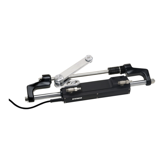
  • Page 59 Diamètre intérieur 36,5 mm - 1.44” Course 184 mm - 7.24” Huile OL460 Ultraflex 560 mm (22.05") UC120E VERSION UC120P-OBF VERSION ATTENTION *La poussée du vérin indiquée est une poussée théorique calculée avec une pression de système de 120 bar. Cette poussée ne correspond pas à...
  • Page 60 ULTRAFLEX Manuel d’installatiotion et d’entretien 2 TRANSPORT 2.1 Avertissements généraux Le poids du produit avec son emballage est 8Kg (18 livres), il peut donc être manutentionné manuellement. AVERTISSEMENT Le personnel chargé de la manipulation de l’installation doit porter des gants de protection et des chaussures de sécurité.
  • Page 61 ULTRAFLEX Manuel d’installatiotion et d’entretien UC120E CONTENU DE L’ EMBALLAGE STANDARD: A ) n°1 corps du vérin équipé de tige, raccords, étriers et bras de renvoi et capteur de position; B) n°1 kit entretoises formé de: n°8 entretoises en plastique;...
  • Page 62 ULTRAFLEX Manuel d’installatiotion et d’entretien 3 INSTALLATION 3.1 Prescriptions minimales arcasse Les dimensions minimum du cockpit sont indiquées ci-dessous. Elles sont nécessaires pour éviter d’endommager le vérin, quand le moteur hors-bord est complètement tourné vers le haut (Tilt). On indique aussi les dimensions du tableau arrière, pour permettre l’installation et le fonctionnement correct du vérin de guidage du moteur.
  • Page 63 ULTRAFLEX Manuel d’installatiotion et d’entretien 3.3 Installation du vérin NOTE La procédure d'installation suivante s'applique aussi bien à UC120E qu'à UC120P-OBF. Il faut consdérer que le vérin UC120P-OBF est en version bâbord. ATTENTION Après avoir enlevé les bouchons de protection des raccords, centrer manuellement la tige (1) par Pendant les phases d’installation utiliser exclusive-...
  • Page 64 ULTRAFLEX Manuel d’installatiotion et d’entretien Positionner la vis sans tête (5) sur la bague En se référant à l’”Application Guide” identifier les entretoises nécessaires à positionner sur la tige moteur. d’espacement (6) et visser cette dernière sur le côté droit du tube de guidage jusqu’à la pousser au fin de course, en cas d’applications port aussi.
  • Page 65 ULTRAFLEX Manuel d’installatiotion et d’entretien 12 Insérer les rondelles (13) dans les deux extré- 11 Faire sortir la tige du tube de guidage (8) de mités de la tige du tube de guidage (8), graisser le l’étrier (9). filetage des écrous autofreinés (14) avec de la graisse antigrippage type MOLYKOTE®...
  • Page 66 ULTRAFLEX Manuel d’installatiotion et d’entretien 3.3.1 Positionnement cloison (mod. UC120E) À l'aide du gabarit de perçage fourni en annexe, Faire passer le câble pourvu de connecteur à percer un trou de ø 25 mm (1") et trois trous de 3 mm travers la cloison.
  • Page 67 ULTRAFLEX Manuel d’installatiotion et d’entretien 3.4 Installation tuyaux Les deux raccords assemblés sur le corps du vérin sont déjà orientés et prêts pour être utilisés. Pour en modifier l’orientation procéder de la façon suivante: desserrer l’écrou de blocage (A) à l’aide d’une clé de 11/16";...
  • Page 68 ULTRAFLEX Manuel d’installatiotion et d’entretien 3.5 Types d'installation Le vérin hydraulique de la série UC120 peut être installé dans différentes configurations, comme décrit au pa- ragraphe 1.3. Le système INTEGRA prévoit le raccordement de chaque vérin directement au groupe hydraulique.
  • Page 69 Ne pas modifier ou ajouter n’importe quel dispositif au système, sans autorisation écrite ou intervention technique de la Société ULTRAFLEX qui atteste dans la description de l’intervention la modification effectuée. Ne pas utiliser l’appareillage pour un but différent de celui auquel il a été destiné et qui est spécifié dans le manuel d’installation et d’entretien.
  • Page 70 ULTRAFLEX Manuel d’installatiotion et d’entretien 5 ENTRETIEN 5.1 Entretien ordinaire AVERTISSEMENT La non-observation des contrôles d’entretien peut causer la perte de guidage avec des dommages matériels et/ou des lésions personnelles. Les conditions requises pour l’entretien varient selon le climat, la fréquence et le mode d’emploi. Des inspections au moins annualles sont nécessaires;...
  • Page 71 ULTRAFLEX Manuel d’installatiotion et d’entretien 6 DEMOLITION 6.1 Démolition Si la machine doit être mise hors service pour quelques raisons que ce soit, les règles fondamentales suivantes doivent être observées pour la protection de l’environnement. Gaines, conduits flexibles, composants de matériel plastique ou non métalliques, devront être désassemblés et éliminés séparement.
  • Page 72 ULTRAFLEX S.p.A. 16015 Casella (Genova) Italia - Via Crose, 2...

Ce manuel est également adapté pour:

Integra uc120eIntegra uc120p-obf

Table des Matières