Télécharger Imprimer la page

Ultraflex UC 378 Manuel D'installation Et D'entretien

Verin hydraulique pour moteurs in-bord

Publicité

Les langues disponibles

Les langues disponibles

Liens rapides

Installation and Maintenance Manual
HYDRAULIC CYLINDER FOR
INBOARD ENGINES
UC 378
ULTRAFLEX
R
SOCIO
UK
F
I
pag. 21
page. 41
page. 2
(Dr. No. 23419/c 08/05/2015)

Publicité

loading

Sommaire des Matières pour Ultraflex UC 378

  • Page 1 Installation and Maintenance Manual HYDRAULIC CYLINDER FOR INBOARD ENGINES UC 378 ULTRAFLEX SOCIO pag. 21 page. 41 page. 2 (Dr. No. 23419/c 08/05/2015)
  • Page 2 Products for pleasure boats are constantly tested to check their conformity with the 2013/53/EU. "ULTRAFLEX has over 80 years of experience in the marine industry and is a world leader in the production of mechanical, hydraulic and electronic steering systems, control boxes and steering wheels for any kind of pleasure, fishing or commercial boats.
  • Page 3: Table Des Matières

    ULTRAFLEX Installation and Maintenance Manual TABLE OF CONTENTS MANUAL USE AND SYMBOLS USED........................4 INTRODUCTION..........................5 WARRANTY..........................5 SECTION 1 - PRODUCT DESCRIPTION HYDRAULIC STEERING SYSTEM OPERATION..................6 WARNINGS FOR THE CORRECT PRODUCT USE ..............6 SYSTEM CONFIGURATIONS.........................7 CYLINDER DESCRIPTION......................8 TECHNICAL FEATURES..........................8 SECTION 2 - TRANSPORT GENERAL WARNINGS..........................9...
  • Page 4: Manual Use And Symbols Used

    ULTRAFLEX Installation and Maintenance Manual MANUAL USE AND SYMBOLS USED THE INSTALLATION AND MAINTENANCE MANUAL is the document accompanying the product from its sale to its replacement and discharge. The manual is an important part of the product itself. It is necessary to read carefully the manual, before ANY ACTIVITY involving the product, handling and unloading included.
  • Page 5: Introduction

    We remind you that only marked steering systems must be used on the boats marked . We inform you that the ULTRAFLEX warranty is null if some ULTRAFLEX components are installed on a steering system together with products of other brands. page 5...
  • Page 6: Product Description

    1 PRODUCT DESCRIPTION 1.1 Hydraulic steering system operation All ULTRAFLEX hydraulic steering systems are designed in conformity with UNI-EN-ISO 10592 and A.B.Y.C. P21 regulations. All ULTRAFLEX steering systems can operate at temperatures between -18°C (0°F) and +77°C (+170°F). All the components are made for the marine environment, using materials and working processes which offer long life and safety under the most extreme conditions.
  • Page 7: System Configurations

    Installation and Maintenance Manual 1.3 System configurations The hydraulic cylinder for inboard engine UC 378 model can be installed with different configurations according to the number and the type of engines used with a single or dual engine steering system.
  • Page 8: Cylinder Description

    Installation and Maintenance Manual 1.4 Cylinder description UC 378 is a hydraulic inboard cylinder which has been designed and manufactured to be used as a component in the hydraulic steering systems, as described in the previous paragraph. The cylinder with mobile rod is installed directly to the arm of the helm through the proper ball joint on the end part of the cylinder.
  • Page 9: Transport

    ULTRAFLEX Installation and Maintenance Manual 2 TRANSPORT 2.1 General warnings The product weight with its packaging is 9kg (19 pounds) and so it can be handled manually. WARNING The staff in charge of handling must operate with protective gloves and safety shoes.
  • Page 10: Necessary Tools

    ULTRAFLEX Installation and Maintenance Manual 3 INSTALLATION 3.1 Necessary tools Torque wrench Open end Open end wrench wrench 24 mm (0,94") 22 mm (0,86") 3.2 Cylinder installation DANGER An arm (1) shorter than the one indicated could move the helm instead of the cylinder up to the end stroke by causing the breaking of the steering guide and the following loss of boat control.
  • Page 11 ULTRAFLEX Installation and Maintenance Manual Mount it by looking for the "x" imaginary line parallel to Check if the arm the transom. It joins the arm hole in the two "A" and "B" end (1) and the helm stroke positions of the cylinder when the angles between the blade (2) are aligned, two "A"...
  • Page 12: Hose Installation

    ULTRAFLEX Installation and Maintenance Manual 3.3 Hose installation The two fittings mounted on the cylinder body are already oriented and are ready to be used. DANGER The fittings mounted on the cylinder cannot be oriented. If they are unscrewed, they could be broken and the cylinder is no more usable.
  • Page 13: Type Of Installation

    Connect hoses as shown in the following pictures: The UC 378 hydraulic cylinder for inboard engines can be installed with different configurations according to the number and the type of engines used with a single or dual steering system. The possible configurations...
  • Page 14: Filling And Purging

    - Mobil DTE 11M NOTICE ULTRAFLEX will not be able to ensure the compatibility of the above mentioned oils with OL150 if the oil manufacturers vary their formulation; in particular, it will not be able to ensure its compliance with standard ISO 10592 concerning hydraulic steering systems.
  • Page 15: Single Steering Station/ Single Cylinder

    ULTRAFLEX Installation and Maintenance Manual 3.5.1 Single steering station/ single cylinder - Unscrew the two bleed valves and manually push the cylinder body to one side until it stops as shown in picture 1. - Position the oil bottle as explained in the picture.
  • Page 16: Dual Steering Station/Single Cylinder

    ULTRAFLEX Installation and Maintenance Manual 3.5.2 Dual steering station/ single cylinder bleed - Manually unscrew the two bleed valves valves on the cylinder "T" fittings and push the cylinder up to the end stroke. vent plug - Position the oil bottle near the (upper) main steering station according to what is previously described.
  • Page 17: Safety Warnings During Use And Installation

    4.1 Safety warnings during use and installation RESPECT STRICTLY the following safety rules: ULTRAFLEX declines all responsibility in case the user does not follow these rules and it is not responsible for negligence during the use of the system. DANGER DO NOT PUT HANDS BETWEEN THE MOVING PARTS.
  • Page 18: Ordinary Maintenance

    WARNING Whenever the following checks need the removal and/or disassembly of the steering system components, such work must be carried by specialized staff. ULTRAFLEX offers general information only and is not responsible for any consequences resulting from incorrect disassembly. PROBLEM...
  • Page 19 • Wrong oil has been used. • Drain the filling and bleeding system. stiff and hard to turn, even when the boat is not moving. WARNING ULTRAFLEX is not responsible for damage caused fluids that recommended in this manual and so the warranty is cancelled.
  • Page 20: Dismantling

    ULTRAFLEX Installation and Maintenance Manual 6 DISMANTLING 6.1 Dismantling When for any reason, the steering system is put out of service, it is necessary to follow some rules in order to respect the environment. Sheaths, pipelines, plastic or non-metallic components must be disassembled and disposed of separately.
  • Page 21 Manuale di installazione e manutenzione CILINDRO IDRAULICO PER MOTORI ENTROBORDO UC 378 ULTRAFLEX SOCIO...
  • Page 22 Gentile Cliente, La ringraziamo per aver scelto un prodotto ULTRAFLEX. ULTRAFLEX è da anni un punto di riferimento nei sistemi di guida nel settore della nautica da diporto e professionale. Da sempre la produzione ULTRAFLEX è sinonimo di grande affidabilità e sicurezza.
  • Page 23 ULTRAFLEX Manuale di installazione e manutenzione INDICE GENERALE USO DEL MANUALE E SIMBOLOGIA IMPIEGATA..................24 LETTERA INFORMATIVA..........................25 GARANZIA..........................25 SEZIONE 1 - DESCRIZIONE DEL PRODOTTO FUNZIONAMENTO DI UN SISTEMA DI GUIDA IDRAULICO................26 AVVERTENZE PER IL CORRETTO UTILIZZO DEL PRODOTTO..............26 CONFIGURAZIONI DEL SISTEMA......................27 DESCRIZIONE DEL CILINDRO....................28...
  • Page 24: Uso Del Manuale E Simbologia Impiegata

    ULTRAFLEX Manuale di installazione e manutenzione USO DEL MANUALE E SIMBOLOGIA IMPIEGATA Il MANUALE DI INSTALLAZIONE E MANUTENZIONE è il documento che accompagna il prodotto dal momento della sua vendita fino alla sua sostituzione e smaltimento. Risulta cioè essere parte integrante dello stesso.
  • Page 25: Lettera Informativa

    GARANZIA ULTRAFLEX garantisce che i suoi prodotti sono costruiti a regola d'arte e che sono privi di difetti di fabbricazione e di materiali. Questa garanzia è valida per un periodo di due anni decorrenti dalla data di fabbricazione dei prodotti ad eccezione dei casi in cui questi siano installati ed usati su barche da lavoro o comunque su barche ad utilizzo commerciale, nel qual caso la garanzia è...
  • Page 26: Descrizione Del Prodotto

    I sistemi idraulici di guida ULTRAFLEX sono progettati in conformità alla normativa UNI-EN-ISO 10592 ed alla A.B.Y.C. P21. I sistemi di guida ULTRAFLEX sono in grado di operare in un campo di temperatura ambiente compreso tra -18°C (0°F) e +77°C (+170°F), tutti i loro componenti sono stati realizzati specificatamente per l'ambiente...
  • Page 27: Configurazioni Del Sistema

    Manuale di installazione e manutenzione 1.3 Configurazioni del sistema Il cilindro idraulico per motori entrobordo modello UC 378 può essere installato in diverse configurazioni in funzione del numero e del tipo di motori utilizzati in accoppiamento ad un sistema di guida singola o doppia.
  • Page 28: Descrizione Del Cilindro

    Manuale di installazione e manutenzione 1.4 Descrizione del cilindro Il cilindro idraulico entrobordo UC 378 è progettato e costruito per essere utilizzato come componente di un sistema di guida idraulico come descritto nel paragrafo precedente. Il cilindro a stelo mobile viene applicato direttamente al braccetto del timone attraverso l'apposito snodo sferico di cui è...
  • Page 29: Avvertenze Generali

    ULTRAFLEX Manuale di installazione e manutenzione 2 TRASPORTO 2.1 Avvertenze generali Il peso del prodotto con il suo imballo è di circa 9Kg (19 pounds) e quindi la sua movimentazione può essere effettuata manualmente. AVVERTENZA Il personale addetto alla manipolazione del carico deve operare con guanti protettivi e scarpe anti infortunistiche.
  • Page 30: Utensili Necessari

    ULTRAFLEX Manuale di installazione e manutenzione 3 INSTALLAZIONE 3.1 Utensili necessari Chiave Chiave Chiave esagonale dinamometrica esagonale 22 mm (0,86") 24 mm (0,94") 3.2 Installazione del cilindro PERICOLO Un braccio (1) più corto di quello indicato potrebbe mandare in fine corsa il timone anzichè il cilindro provocando la rottura del sistema di guida e la conseguente perdita di controllo dell'imbarcazione.
  • Page 31 ULTRAFLEX Manuale di installazione e manutenzione Procedere al montaggio cercando la linea immaginaria Verificare che il "x", parallela allo specchio di poppa, che unisce il foro del braccetto (1) e la pala braccetto nelle due posizioni di fine corsa del cilindro "A" e del timone (2) siano "B"...
  • Page 32: Installazione Tubi

    ULTRAFLEX Manuale di installazione e manutenzione 3.3 Installazione tubi I due raccordi montati sul corpo del cilindro sono già orientati e pronti per essere utilizzati. PERICOLO I raccordi montati sul cilindro NON sono orientabili. Il loro eventuale svitamento ne comporta la conseguente rottura rendendo il cilindro inutilizzabile.
  • Page 33: Tipi Di Installazione

    Eseguire sempre con attenzione l'esatto collegamento dei tubi come rappresentato nelle seguenti illustrazioni. Il cilindro idraulico per motori entrobordo modello UC 378 può essere installato in diverse configurazioni in funzione del numero e del tipo di motori utilizzati in accoppiamento ad un sistema di guida a singola o doppia stazione.
  • Page 34: Riempimento E Spurgo

    - Mobil DTE 11M NOTA ULTRAFLEX non potrà garantire la compatibilità degli oli citati con OL150 in caso di variazione alle formulazioni da parte dei produttori degli oli stessi, in particolare non potrà garantirne la rispondenza alla ISO 10592 relativa ai sistemi di guida idraulici. Eventuali cali prestazionali e/o di durata non saranno in nessun caso imputabili ad ULTRAFLEX.
  • Page 35: Stazione Di Guida Singola/Cilindro Singolo

    ULTRAFLEX Manuale di installazione e manutenzione 3.5.1 Stazione di guida singola/ cilindro singolo - Svitare le due valvole di spurgo e portare manualmente lo stelo in fine corsa da un lato come indicato in figura 1. - Posizionare la bottiglia dell'olio come indicato in figura.
  • Page 36: Stazione Di Guida Doppia/Cilindro Singolo

    ULTRAFLEX Manuale di installazione e manutenzione 3.5.2 Stazione di guida doppia/ cilindro singolo - Svitare manualmente le due valvole di valvole spurgo sui raccordi a T del cilindro e di spurgo portare il cilindro in fine corsa. tappo con sfiato - Posizionare la bottiglia dell'olio in pros- simità...
  • Page 37: Avvertenze Di Sicurezza

    RISPETTATE TASSATIVAMENTE le precauzioni ed i criteri di sicurezza indicati qui di seguito. ULTRAFLEX. declina ogni responsabilità nel caso in cui l'utilizzatore non li osservi, così come non è respon- sabile per qualsiasi tipo di negligenza che venga commessa durante l'utilizzo del sistema.
  • Page 38: Manutenzione Ordinaria

    Ogni qualvolta i seguenti controlli richiedano la rimozione e/o smontaggio dei componenti del sistema di guida, richiedere l'intervento di personale qualificato. ULTRAFLEX offre le indicazioni generali e non può essere ritenuta responsabile per eventuali informazioni e conseguenze derivanti da un errato smontaggio.
  • Page 39 AVVERTENZA Eventuali danni causati dall'uso di fluidi di- versi da quelli raccomandati in questo ma- nuale, non sono in alcun modo imputabili ULTRAFLEX e annullano automaticamente la garanzia. La timoneria è rigida e diffi- • Introduzione nella valvola, di AVVERTENZA cilmente manovrabile, anche sporcizia o trucioli.
  • Page 40: Smantellamento

    ULTRAFLEX Manuale di installazione e manutenzione 6 SMANTELLAMENTO 6.1 Smantellamento Qualora si intenda, per qualsiasi motivo, mettere fuori servizio il sistema di guida, è necessario osser- vare alcune regole fondamentali atte a salvaguardare l’ambiente. Guaine, condotti flessibili, componenti di materiale plastico o comunque non metallico, dovranno essere smon- tati e smaltiti separatamente.
  • Page 41 Manuel d'installation et d'entretien VERIN HYDRAULIQUE POUR MOTEURS IN-BORD UC 378 ULTRAFLEX SOCIO...
  • Page 42 Clients; Le système de Gestion Environnementale de la Qualité ULTRAFLEX est certifié CISQ-IQNet par le Registre Italien des Navires (RINA), en conformité avec la Norme UNI EN ISO 14001. Certificat ULTRAFLEX n° EMS- 1282/S.
  • Page 43 ULTRAFLEX Manuel d'installation et d'entretien INDEX GENERAL EMPLOI DU MANUEL ET SYMBOLES UTILISES....................44 LETTRE D'INFORMATION...........................45 GARANTIE............................45 SECTION 1 - DESCRIPTION DU PRODUIT FONCTIONNEMENT D'UN SYSTEME DE GOUVERNEMENT HYDRAULIQUE..........46 AVERTISSEMENTS POUR L'EMPLOI CORRECT DU PRODUIT...............46 CONFIGURATIONS DU SYSTEME....................47 DESCRIPTION DU VERIN......................48 CARACTERISTIQUES TECHNIQUES DU VERIN................48...
  • Page 44: Emploi Du Manuel Et Symboles Utilises

    ULTRAFLEX Manuel d'installation et d'entretien EMPLOI DU MANUEL ET SYMBOLES UTILISES Le MANUEL D'INSTALLATION ET D'ENTRETIEN est le document qui accompagne le produit de sa vente jusqu'à son remplacement et sa démolition. C'est donc une partie fondamentale du manuel lui-même.
  • Page 45: Lettre D'information

    GARANTIE La Société ULTRAFLEX garantit que ses produits sont fabriqués à règles d'art et qu'ils n'ont aucun défaut de fabrication et de matériels. Cette garantie a une validité de deux années à partir de la date de fabrication des produits à l'exception des cas où...
  • Page 46: Description Du Produit

    AVERTISSEMENT Les systèmes de conduite ULTRAFLEX ne doivent pas être appliqués sur des bateaux équipés avec motorisations dépassant les puissances maximales installables établies par le chantier.
  • Page 47: Configurations Du Systeme

    Manuel d'installation et d'entretien 1.3 Configurations du système Le vérin hydraulique pour moteurs in-bord modèle UC 378 peut être installé dans des configurations différentes selon le nombre et le type de moteurs utilisés en accouplement avec un système de gouvernement unique ou double.
  • Page 48: Description Du Verin

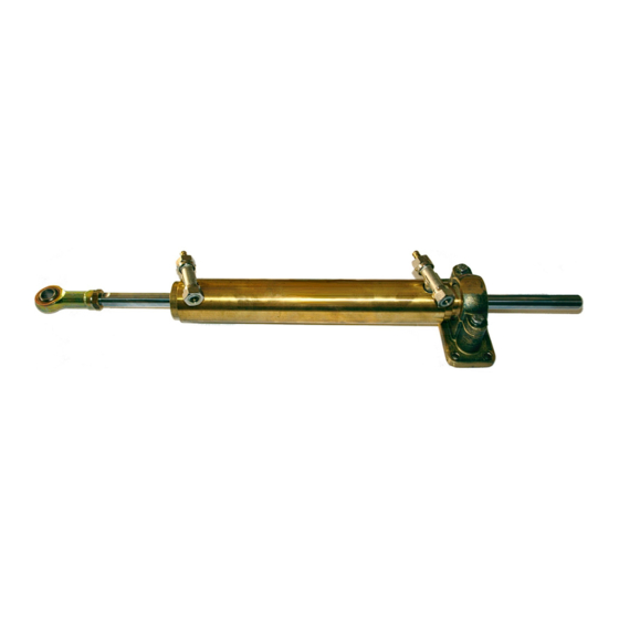
    Manuel d'installation et d'entretien 1.4 Description du vérin Le vérin hydraulique in-bord UC 378 a été conçu et fabriqué pour être utilisé comme composant d'un système de gouvernement hydraulique comme décrit au paragraphe précédent. Le vérin à tige mobile est apppliqué directement au bras du gouvernail à travers l'articulation à rotule spéciale qui se trouve dans sa partie terminale.
  • Page 49: Avertissements Generaux

    ULTRAFLEX Manuel d'installation et d'entretien 2 TRANSPORT 2.1 Avertissements généraux Le poids du produit avec son emballage est 9Kg (19 livres), il peut donc être manutentionné manuellement. AVERTISSEMENT Le personnel chargé de la manipulation du chargement doit porter des gants de protection et des chaussures de sécurité.
  • Page 50: Outils Necessaires

    ULTRAFLEX Manuel d'installation et d'entretien 3 INSTALLATION 3.1 Outils nécessaires Clé Clé Clé dynamométrique hexagonale hexagonale 24 mm (0,94") 22 mm (0,86") 3.2 Installation du vérin DANGER Un bras (1) plus court que celui indiqué pourrait faire en sorte que le gouvernail plutôt que le vérin atteigne le fin de course en provoquant la rupture du système de gouvernement et la perte conséquente...
  • Page 51 ULTRAFLEX Manuel d'installation et d'entretien Procéder au montage cherchant la ligne imaginaire "x", Vérifier que le parallèle au tableau arrière, qui unit le trou du bras dans les bras (1) et la pelle du deux positions "A" et "B" de fin de course du vérin quand les gouvernail (2) soient angles entre les deux position "A"...
  • Page 52: Installation Tuyaux

    ULTRAFLEX Manuel d'installation et d'entretien 3.3 Installation tuyaux Les deux raccords montés sur le corps du vérin sont déjà orientés et prêts pour être utilisés. DANGER Les raccords montés sur le vérin NE sont PAS orientables. Leur dévissage éventuel en comporte la rupture conséquente en rendant le vérin inutilisable.
  • Page 53: Types D'installation

    Toujours connecter les tuyaux avec attention comme montré dans les dessins ci-dessous. Le vérin hydraulique pour moteurs in-bord modèle UC 378 peut être installé dans plusieurs configurations en fonction du nombre et du type de moteurs utilisés avec un système de gouvernement unique ou double.
  • Page 54: Remplissage Et Purge

    L'huile hydraulique OL150 est spécifiquement formulée pour ULTRAFLEX afin de maintenir le plus longtemps possible pendant le temps le haut niveau de qualité et de performance des produits ULTRAFLEX. Sa formule particulière "Sans Zinc" favorise la protection contre l’oxydation marine. Le mélange particulier des composants antiusures et stabilisants, dont OL150 est composé, permettent d’obtenir un résultat optimal...
  • Page 55: Poste De Gouvernement Unique/Verin Unique

    ULTRAFLEX Manuel d'installation et d'entretien 3.5.1 Poste de gouvernement unique/ vérin unique - Dévisser les deux soupapes de purge et pousser manuellement la tige jusqu'à la fin de sa course d'un côté comme indiqué dans la figure 1. - Positionner la bouteille de l'huile comme indiqué dans la figure.
  • Page 56: Poste De Gouvernement Double/Verin Unique

    ULTRAFLEX Manuel d'installation et d'entretien 3.5.2 Poste de gouvernement double/ vérin unique - Dévisser manuellement deux soupapes soupapes de purge sur les raccords en T de purge du vérin et porter le vérin jusqu'à la fin de bouchon sa course.
  • Page 57: Avertissements De Securite

    RESPECTER RIGOUREUSEMENT les précautions et les critères de sécurité indiqués ci-dessous. La Société ULTRAFLEX. décline toute responsabilité au cas où l'usager ne les respecterait pas; elle n'est pas non plus responsable pour tout type de négligence commise pendant l'emploi du système.
  • Page 58: Entretien Ordinaire

    Toutes les fois que les contrôles suivants nécessitent du désasemblage des composants du système de gouvernement, il faut demander l'intervention du personnel qualifié. La Société ULTRAFLEX offres des indications générales et décline donc toute responsabilité pour les informations et les conséquences dérivant d'un désassemblage incorrect.
  • Page 59 à manoeuvrer, même de remplissage et de purge. quando le bateau est à AVERTISSEMENT l'arrêt. La Société ULTRAFLEX décline toute responsabilité et la garantie est automatiquement annulée en cas de dommages causés par l'emploi de fluides différents de ceux qui sont recommandés dans ce manuel.
  • Page 60: Demolition

    ULTRAFLEX Manuel d'installation et d'entretien 6 DEMOLITION 6.1 Démolition Si la machine doit être mise hors service pour quelques raisons que ce soit, les règles fondamentales suivantes doivent être observées pour la protection de l'environnement. aines, conduits flexibles, composants de matériel plastique ou non métalliques, devront être désassemblés et éliminés séparement.
  • Page 61 ULTRAFLEX Manuel d'installation et d'entretien NOTES page 61 de 64 VERIN HYDRAULIQUE POUR MOTEUR IN-BORD...
  • Page 62 ULTRAFLEX Manuel d'installation et d'entretien NOTES page 62 de 64 - VERIN HYDRAULIQUE POUR MOTEUR IN-BORD...
  • Page 63 ULTRAFLEX Manuel d'installation et d'entretien NOTES page 63 de 64 VERIN HYDRAULIQUE POUR MOTEUR IN-BORD...
  • Page 64 ULTRAFLEX S.p.A. 16015 Casella (Genova) Italia - Via Crose, 2...