Assa Abloy OneSystem Instructions De Montage
Table des Matières
Les langues disponibles
Les langues disponibles
Liens rapides
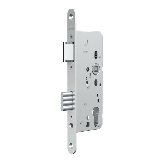
Standard Panik-Einsteckschloss
Standard Panic-mortise Lock
Serrure encastrée anti-panique standard
Serratura antipanico, da incasso, standard
Standaard Panieksteekslot
Montageanleitung / Installation instructions / Instructions de montage
Instruzioni di montaggio / Handleiding voor montage
D0085001
www.assaabloy.de
DE Seite
EN Page
FR Page
IT Pagina 110
NL Pagina 146
The global leader in
door opening solutions
2
38
74
Chapitres
Table des Matières

Manuels Connexes pour Assa Abloy OneSystem


Sommaire des Matières pour Assa Abloy OneSystem
- Page 74 D0085001 10.2015 Copyright © 2015, ASSA ABLOY Sicherheitstechnik GmbH Cette documentation et toutes les parties annexes sont protégées par la loi sur les droits d’auteur. Toute exploitation et modification dépassant les limites du cadre d'usage conforme prévu par la loi sur les droits d'auteur sont interdites et passibles de peine, sans autorisation préalable de la société...
- Page 75 Serrures de sécurité de la série OneSystem........
-
Page 76: Introduction
Toutes ces propriétés se retrouvent dans les serrures de sécurité de la série OneSystem (Fig. 1). La gramme de serrures OneSystem comprend, outre les variantes décrites dans la présente notice d'instructions, de nombreuses autres variantes de serrures. - Page 77 Fig. 1 : En option : Série OneSystem verrouillage supérieur Gamme de En option : produits anti- verrouillage supérieur panique standard option: monitoring option: monitoring Fig. 2 : pour portes à un battant pour portes à deux battants avec Broche de broche de déverrouillage dans le pêne déverrouillage...
-
Page 78: À Propos De Cette Notice
À propos de cette notice Groupe cible Cette notice a été rédigée à l'attention des artisans et du personnel spécialement formé. L'artisan en charge du montage doit être qualifié pour exécuter des travaux de fraisage et d'autres usinages du bois et du métal. Lisez cette notice afin de pouvoir installer et utiliser la serrure en toute sécurité... -
Page 79: Consignes De Sécurité
Consignes de sécurité Avertissement ! Danger de mort et risque de blessure liés à une modification des caractéris- tiques de sécurité : « Les caractéristiques de sécurité de ce produit constituent une condition préalable essentielle pour sa conformité aux normes DIN EN 179 et DIN EN 1125. - Page 80 Avertissement ! Danger de mort, risque de blessure et de dommages matériels liés à une restric- tion du mouvement de la porte : Tous les éléments de verrouillage doivent être montés de façon à ne pas entraver la liberté de mouvement de la porte. Les portes doivent uniquement être maintenues fermées avec les fermetures homologuées.
-
Page 81: Explication Des Fonctions Anti-Panique B, C, D, E Et P
Explication des fonctions anti-panique B, C, D, E et P ASSA ABLOY Sicherheitstechnik GmbH différencie cinq variantes de fonctions anti-panique (Tab. 1), désignées par les lettres B, C, D, E et P. Remarque ! Principe général : Une porte avec une serrure anti-panique peut toujours être ouverte de l'intérieur par la béquille de la porte, même si elle est verrouillée. -
Page 82: Utilisation Conforme
Utilisation conforme En fonction de l’axe (« Caractéristiques techniques », page 104), la serrure anti-panique standard est appropriée pour les portes pleines. Elle fait partie du système de fermeture de porte. Une fermeture de porte est une unité fonctionnelle composée d'une serrure et des accessoires associés. Une serrure anti-panique standard avec fonction anti-panique P sert au verrouil- lage de porte dans les zones de sécurité... -
Page 83: Clé De Classification
Clé de classification DIN EN 12209 La clé de classification à onze caractères indique les caractéristiques des serrures selon la norme DIN EN 12209. La clé de classification de cette serrure est : 3 M 6 1 0 C 5 H A 2 0 Le Tab. - Page 84 DIN EN 1125 – Fonction anti-panique B, C, D et E La clé de classification à dix caractères indique les caractéristiques des serrures selon la norme DIN EN 1125. La clé de classification de cette serrure est : 3 7 7 B 1 3 2 2 A Le Tab.
- Page 85 DIN EN 179 – Fonction anti-panique B, C, D, E et P La clé de classification à dix caractères permet d’indiquer les propriétés des serrures selon la norme EN 179. La clé de classification de cette serrure est : 3 7 7 B 1 3 5 2 A X Le Tab.
-
Page 86: Explication De La Terminologie Employée
Explication de la terminologie employée Terme Description Verrouillage supérieur Le boîtier est équipé du mécanisme d‘accouplement pour un verrouillage supérieur. Fouillot / carré Le carré est une tige carrée qui passe à travers le fouillot et dont les extrémités sont chacune logées dans une béquille. Coffre de serrure Le coffre de serrure intègre le mécanisme de la serrure. - Page 87 Fig. 3: Vue schématisée de la serrure anti-panique Fig. 4 : Jeu de feuillure Consignes de sécurité...
-
Page 88: Montage
Montage Avertissement ! Danger de mort et risque de blessure dus à un montage incorrect ou erroné de la barre de manœuvre horizontale selon DIN EN 1125 : La hauteur de montage courante pour la barre de manœuvre horizontale se situe dans un intervalle de 900 mm à 1100 mm à compter de la surface du plancher fini. -
Page 89: Montage De La Serrure
Montage de la serrure Préparation de la mortaise Préparation de la 1. Fraisez la mortaise mortaise (« Dimensions de fraisage de la mortaise pour la serrure », page 90). 2. Réalisez les perçages pour les vis de fixation (Fig. 13, page 106). 3. -
Page 90: Dimensions De Fraisage De La Mortaise Pour La Serrure
La mortaise pour la serrure doit être fraisée avec un jeu suffisant mais pas trop grand pour permettre une insertion facile du coffre de la serrure. La profondeur de fraisage doit être adaptée à l’axe de la serrure. ASSA ABLOY Sicherheitstechnik recommande les Tab. 5 dimensions ci-dessous. - Page 91 Réglage du sens d‘ouverture Le sens d’ouverture de la serrure anti-panique est réversible de sorte à pouvoir l’utiliser sur les portes DIN gauche et les portes DIN droite (Fig. 5). Pour ce faire, il faut inverser le pêne avant de monter la serrure sur la porte. Fig.
-
Page 92: Modification Du Côté Anti-Panique
Modification du côté anti-panique Le côté anti-panique de la serrure doit être réglé avant le montage. Le côté anti-panique de la serrure doit être réglé de sorte à ce que la porte puisse être ouverte au moyen de la béquille dans la direction de secours (normalement de l’intérieur vers l’extérieur), indépendamment de l’état de verrouillage de la serrure. -
Page 93: Montage Du Cylindre Profilé
Montage du cylindre profilé La serrure doit être montée dans la porte avant de pouvoir procéder au montage du cylindre profilé (« Montage de la serrure », page 89, « Accessoires, garantie, élimination », page 103). Le cylindre profilé doit être adapté à l’épaisseur et à la garniture de la porte et peut dépasser de 3 mm maxi. - Page 94 Montage des garnitures (selon DIN EN 179) Avertissement ! Danger de mort et risque de blessure dus à un montage incorrect ou erroné de la béquille selon DIN EN 179 : Seul(e)s les garnitures, les contreparties de verrouillage et les parements homologués selon DIN EN 179 sont autorisés pour le montage (« Garnitures », page 96).
- Page 95 Fig. 10 : Monter une garniture Montage des garnitures (selon Fig. 11 : DIN EN 1125) Porte de secours Montez la barre anti-panique (Fig. 11) selon DIN EN 1125 suivant les instructions fournies (« Accessoires, garantie, élimination », page 103). Montage...
-
Page 96: Fonctions Et Utilisation
Fonctions et utilisation Fonction anti-panique ASSA ABLOY Sicherheitstechnik GmbH différencie cinq variantes de fonctions anti-panique (« Explication des fonctions anti-panique B, C, D, E et P », page 81). Les variantes de fonctions anti-panique diffèrent d’un point de vue de leur utilisation et des garnitures à... -
Page 97: Fonction Anti-Panique B, C, D, E, P - Utilisation
Fonction anti-panique B – Utilisation Ouverture de la porte - dans la direction de secours (de l’intérieur) la porte peut 1. Actionnez la barre anti-panique ou la béquille. toujours être La serrure est déverrouillée et la porte peut être ouverte de l’intérieur. ouverte de ... -
Page 98: Fonction Anti-Panique C - Utilisation
Fonction anti-panique C – Utilisation Ouverture de la porte - dans la direction de secours (de l’intérieur) la porte peut 1. Actionnez la barre anti-panique ou la béquille. toujours être La serrure est déverrouillée et la porte peut être ouverte de l’intérieur. ouverte de ... -
Page 99: Fonction Anti-Panique D - Utilisation
Fonction anti-panique D – Utilisation Ouverture de la porte - dans la direction de secours (de l’intérieur) la porte peut 1. Actionnez la barre anti-panique ou la béquille. toujours être La serrure est déverrouillée et la porte peut être ouverte. ouverte de ... -
Page 100: Fonction Anti-Panique E - Utilisation
Fonction anti-panique E – Utilisation Ouverture de la porte - dans la direction de secours (de l’intérieur) la porte peut 1. Actionnez la barre anti-panique ou la béquille. toujours être La serrure est déverrouillée et la porte peut être ouverte. ouverte de Ouverture de la porte - dans le sens opposé... -
Page 101: Fonction Anti-Panique P - Utilisation
Fonction anti-panique P – Utilisation Ouverture de la porte - dans la direction de secours (de l’intérieur) Ce type de serrure n’est pas équipé d’un pêne. L’actionnement de la béquille entraîne le retrait du pêne dormant, de sorte que la porte de secours puisse toujours être ouverte de l’intérieur. -
Page 102: Maintenance
Maintenance Maintenance Avertissement ! Danger de mort et risque de blessure dus à une mauvaise maintenance : La responsabilité liée au montage correct et au contrôle de fonctionnement de la porte de secours est du ressort de l’exploitant. Conformément aux normes DIN EN 1125 et DIN EN 179, le fonctionnement correct des portes de secours doit être contrôlé... -
Page 103: Accessoires, Garantie, Élimination
Accessoires, garantie, élimination www.assaabloy.de Accessories OneSystem barre anti-panique type A OneSystem Set complet barre anti-panique type A – Porte profilées N 2 5 0 0 OneSystem Set complet barre anti-panique type A – Porte pleine N 2 0 0 0 OneSystem barre anti-panique type B OneSystem Set complet barre anti-panique type B –... -
Page 104: Caractéristiques Techniques
Caractéristiques techniques Caractéristiques techniques Désignation Portes profilées Portes pleines Homologuée selon DIN EN 1125:2008, DIN EN 179:2008, DIN EN 12209:2004 Exécution Cylindres profilés, Cylindre de fermeture rond Verrouillage Verrouillage simple Dimensions admissibles 1500 mm x 4000 mm de la porte Masse maxi. -
Page 105: Commutateur Dip
Commutateur DIP DIP Fonction sans fonction Résistance terminale 120 Ω 0 Ω Côté panique La vis de blocage La vis de blocage (« Modification du se trouve du se trouve du côté côté anti-panique », page 92) côté gauche en droit en regar- regardant depuis dant depuis la... -
Page 106: Dimensions Portes Profilées
Dimensions Portes Profilées Fig. 13 : En option : verrouillage supérieur Plan technique contenant les cotes de montage Portes Profilées 6 , 5 Ø 6 , 5 Ø 5 , 5 1 2 3 4 En option : Monitoring En option (“Commutateur DIP”, pagina 105) Caractéristiques techniques... -
Page 107: Dimensions Portes Pleines
Dimensions Portes Pleines Fig. 14 : En option : Plan technique – verrouillage supérieur contenant les cotes de montage Portes Pleines Ø 6 6 , 5 Ø 5 1 2 3 4 En option : Monitoring En option (“Commutateur DIP”, pagina 105) Caractéristiques techniques... -
Page 108: Marquage Ce
DIN EN 1125 et DIN EN 179 sont certifiées comme étant des ferme- tures de portes complètes. La certification des portes de secours complètes est pertinente. (www.assaabloy.de) Serrure anti-panique standard B / C / D / E ASSA ABLOY Sicherheitstechnik GmbH Bildstockstraße 20 72458 Albstadt DEUTSCHLAND La procédure d’essai est encore en cours. - Page 109 Serrure anti-panique standard P ASSA ABLOY Sicherheitstechnik GmbH Bildstockstraße 20 72458 Albstadt DEUTSCHLAND La procédure d’essai est encore en cours. 2014 Le numéro d’essai a été demandé. EN 179:2008 La procédure d’essai est encore en cours. 2014 Le numéro d’essai a été demandé.
- Page 183 Abb. 16 : Achtung! Stopfen einschlagen Sachschaden durch Hammer aus Metall: Das Gewinde kann durch Fig. 16 : einen Hammer aus Metall beschä- Insert plug digt werden. Fig. 16 : Benutzen Sie einen Gummihammer. Enfoncer les bouchons Attention! Attention ! Fig.
- Page 189 Abb. 26: Gewindebacken schließen Fig. 26: Close the threading die Fig. 26: fermer les coussinets de filetage Fig. 26: Chiudere le filiere Afb. 26: Schroefdraadklau- wen sluiten Abb. 27: Drähte entfernen- und Schloss festschrauben Fig. 27: Remove wires and screw the lock in place Fig.
- Page 191 Abb. 29: Montage und Justierung des Schließblechs oben Fig. 29: Installation and adjustment of the striking plate on Fig. 29: Montage et ajustage de la têtière de gâche en haut Fig. 29: Montaggio e regolazione dello scontro superiore Afb. 29: Montage en afstelling van de sluitplaat boven...