IKA RV 10 control Mode D'emploi
Masquer les pouces
Voir aussi pour RV 10 control:
- Mode d'emploi (236 pages) ,
- Mode d'emploi (114 pages) ,
- Mode d'emploi (172 pages)
Table des Matières
Publicité
Les langues disponibles
Les langues disponibles
Liens rapides
Publicité
Table des Matières

Manuels Connexes pour IKA RV 10 control


Sommaire des Matières pour IKA RV 10 control
- Page 1 All manuals and user guides at all-guides.com 20000005223 RV 10 control auto_052017 RV 10 control ® Betriebsanleitung Operating instructions Mode d’emploi Instrucciones de manejo Инструкция по эксплуатации Instrukcja eksploatacji...
- Page 2 All manuals and user guides at all-guides.com KONFORMITÄTSERKLÄRUNG Wir erklären in alleiniger Verantwortung, dass dieses Produkt den Bestimmungen der Richtlinien 2006/42/EG, 2014/35/EU, 2014/30/EU und 2011/65/EU entspricht und mit den folgenden Normen und normativen Dokumenten übereinstimmt: EN 61010-1, -2-051, EN 61326-1, EN 60529 und EN ISO 12100. DECLARATION OF CONFORMITY We declare under our sole responsibility that this product corresponds to the regulations 2006/42/EC, 2014/35/EU, 2014/30/EU and 2011/65/EU and conforms with the following standards or normative documents: EN 61010-1, -2-051, EN 61326-1, EN 60529 and EN ISO 12100.
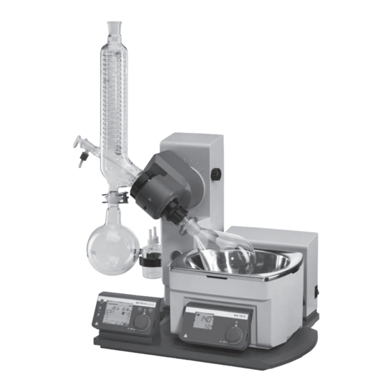
- Page 3 Kompletna konstrukcja z wyposażeniem w ekran ochronny HB 10.1 i pokrywę ochronną HB 10.2 Pos. Bezeichung HB 10.2 Schutzhaube (nicht im Lieferumfang enthalten) HB 10.1 Schutzschild (nicht im Lieferumfang enthalten) Heizbad HB 10 Antrieb RV 10 control Glassatz Halter Woulff’sche Flasche Item Designation HB 10.2 Cover (not included in delivery)
- Page 4 Ursprungssprache Inhaltsverzeichnis Seite Konformitätserklärung Zeichenerklärung Gewährleistung Sicherheitshinweise Bestimmungsgemäßer Gebrauch Auspacken Wissenswertes Vakuum-Regelung: 2-Punkt- und Drehzahlregelung Aufstellung Antrieb RV 10 control Heizbad HB 10 Glassatz Verschlauchung Schnittstellen und Ausgänge Inbetriebnahme Wartung und Reinigung Zubehör Fehlercodes Technische Daten Lösemitteltabelle (Auswahl) Zeichenerklärung Allgemeiner Gefahrenhinweis Verbrennungsgefahr! Gewährleistung...
-
Page 5: Sicherheitshinweise
All manuals and user guides at all-guides.com Sicherheitshinweise Zu Ihrem Schutz • Passen Sie die Menge und Art des Destillationsgutes an die Größe der Lesen Sie die Betriebsanleitung vor Inbetriebnah- Destillationsapparatur an. Der Kühler muss ausreichend wirksam sein. me vollständig und beachten Sie die Sicherheits- Überwachen sie den Kühlmitteldurchfluss am Ausgang des Kühlers. -
Page 6: Bestimmungsgemäßer Gebrauch
• Vermeiden Sie Stöße und Schläge auf das Gerät oder Zubehör. • Das Gerät darf nur von einer Fachkraft geöffnet werden. Bestimmungsgemäßer Gebrauch • Verwendung • Verwendungsgebiet Das Gerät ist in Verbindung mit dem von IKA empfohlenen Zubehör - Laboratorien - Schulen ®... - Page 7 40 °C eingestellt. Das Kühlwasser für den Kondensationskühler heitsanhebung"! sollte nicht wärmer als 20 °C sein (60-40-20 Regel). Mit dem Rotationsverdampfer RV 10 control können neben allen ma- Zur Vakuumerzeugung sollte eine chemiefeste Membranpumpe mit nuellen sowie halbautomatischen Verdampfungsoperationen auch voll-...
- Page 8 Leiseres Arbeiten und genauere Vakuumregelung sind möglich. Die Drehzahl-Vakuum-Regelung wird am RV 10 control automatisch eingestellt, sobald eine geeignete Vakuumpumpe angeschlossen ist. Mit dieser Regelungsart ist eine automatische Siedepunkterkennung möglich, d.h das System sucht und hält im automatischen Modus den Siedepunkt des Lösemittels.
- Page 9 All manuals and user guides at all-guides.com Aufstellung Antrieb RV 10 control Lösen Sie die Klemmvorrichtung zur Winkeleinstellung des Rotations- antriebes auf der rechten Liftseite durch Drehen der Griffschraube (E) Achtung! Transportsicherung lösen (Fig. 4a)! gegen den Uhrzeigersinn (durch leichtes Drücken und gleichzeitiges Drehen lässt sich die Griffschraube (E) weiter aus- bzw.
- Page 10 All manuals and user guides at all-guides.com Erstinbetriebnahme - Montage der Dichtung RV 10.8001 Führen Sie das Dampfdurchführungsrohr bis auf Anschlag ein. Verriegeln Sie anschließend diese Arretierung durch Drehen um 60° im Dampfdurchführungsrohr einsetzen (1). Uhrzeigersinn (Fig. 10). ...
- Page 11 All manuals and user guides at all-guides.com Montage Glassatz Fig. 13b Fig. 13a RV 10.2 unbeschichteten RV 10.1 unbeschichteten RV 10.20 beschichtet RV 10.10 beschichtet 12 (4x) 13 (4x) 12 (2x) 13 (2x) Fig. 13d Fig. 13c RV 10.4 unbeschichteten RV 10.3 unbeschichteten RV 10.40 beschichtet RV 10.30 beschichtet...
- Page 12 All manuals and user guides at all-guides.com 13 (4x) 12 (4x) 13 (4x) 12 (4x) RV 10.6 unbeschichteten RV 10.5 unbeschichteten Fig. 13e Fig. 13f RV 10.60 beschichtet RV 10.50 beschichtet Pos. Bezeichnung Menge RV 10.1 RV 10.2 RV 10.3 RV 10.4 RV 10.5 RV 10.6...
- Page 13 All manuals and user guides at all-guides.com Montage der Scheibe Tropfkante Fig. 13g Fig. 13h Hinweis: Achten Sie auf die korrekte Lage der Scheibe. Das PTFE Rohr (5) mit der Scheibe (18) kann optinal bei den vertikalen Glassätzen montiert werden. Es dient zur Befüllung des Verdampferkolbens bei Unterdruck im Glassatz.
- Page 14 All manuals and user guides at all-guides.com Wasser Vakuum Wasser RV 10.1 unbeschichteten RV 10.10 beschichtet Fig. 14b Wasser Vakuum Wasser RV 10.2 unbeschichteten RV 10.20 beschichtet Fig. 14c...
- Page 15 All manuals and user guides at all-guides.com Wasser Vakuum Wasser RV 10.3 unbeschichteten RV 10.30 beschichtet Fig. 14d Vakuum RV 10.4 unbeschichteten Fig. 14e RV 10.40 beschichtet...
- Page 16 All manuals and user guides at all-guides.com Wasser Vakuum RV 10.5 unbeschichteten Wasser RV 10.50 beschichtet Fig. 14f Wasser Vakuum Wasser RV 10.6 unbeschichteten RV 10.60 beschichtet Fig. 14g...
- Page 17 All manuals and user guides at all-guides.com Demontage Kühler Anschluss RV 10.4002 Verwenden Sie den mitgelieferten Ringschlüssel zum Lösen festsitzen- der Überwurfmuttern. Lösen Sie die Überwurfmutter durch Drehen gegen den Uhrzeigersinn. Lösen Sie das Klettband. Fig. 15b Spule frei drehbar Saugrichtung entspricht der Kennzeichnung durch den...
- Page 18 All manuals and user guides at all-guides.com Vakuum - Drehzahlgeregelter Betrieb Für einen Vakuum Regelbetrieb mit drehzahlgeregelter Pumpe wird kein zusätzliches Ventil benötigt. Schließen Sie den Saugschlauch der Pumpe direkt an den Schlauchanschluss des Drucksensors an. Verbinden Sie die elektrische Steuerleitung mit dem RV10 control (Fig. 15e). Fig.
- Page 19 All manuals and user guides at all-guides.com Wasser Schließen Sie den mitgelieferten Wasserablassschlauch durch Stecken des Nippels bis zum Anschlag in die Anschlussbuchse (Fig. 18). Schließen Sie den Wasserzulauf an Ihre Wasserversorgung an (Fig. 16a; Fig. 16b mit optionalem Drosselventil Wasser RV 10.5001). Beachten Sie Achtung! Achten Sie auf den korrekten Anschluss von Zu- und Ablauf die technischen Daten zur Wasserversorgung.
- Page 20 All manuals and user guides at all-guides.com Schematische Darstellung Anschluss Rückseite Stecken Sie das Ventilanschlusskabel (RV 10.5001 oder RV 10.4001/2, bzw. RV 10.4003 Valve) bzw. das Anschlusskabel (RV 10.4003 Pump control) in die vorgesehene Buchse (Fig. 20) oder schließen Sie die drehzahlgeregelte Vakuumpumpe an. Damit wechselt der RV10 control automatisch in den Drehzahl-Vakuum-Regelbetrieb.
-
Page 21: Schnittstellen Und Ausgänge
IKA ® -Software Paket unter MS Windows zur Steuerung des Gerätes und zur Erfassung der Gerätedaten, das auch grafische Eingaben von z.B. Drehzahlrampen erlaubt. Nachfolgend sehen Sie eine Übersicht der von den IKA ® Control- Geräten verstandenen (NAMUR)-Befehlen. Fig. 23 Installation Laden Sie zuerst den aktuellen Treiber für IKA... - Page 22 All manuals and user guides at all-guides.com Verwendete Abkürzungen: Variablenwert, Integerzahl Temperatur Heizbad Sicherheitstemperatur Heizbad Drehzahl Intervallzeit (1-100 Sekunden, 1 <= m >= 100) Timer (1-200 Minuten, 1 <= m >= 200) Liftposition oben (OUT_SP_62 1-> drive lift up) Liftposition unten (OUT_SP_62 1-> drive lift down) Wert Vakuumkontroller Hysterese Vakuumkontroller Temperiermedium (OUT_SP_74 0=Öl, OUT_SP_74 1=Wasser)
- Page 23 All manuals and user guides at all-guides.com Inbetriebnahme Allgemeine Informationen zur Menüführung Funktionsbeschreibung (Zustand bei Auslieferung) Menü wählen Werkseinstellung Wählen Sie durch Drehen des Dreh-/ Drückknopfes nach links/ rechts Die im Folgenden abgebildeten Werte entsprechen dem Zustand bei den gewünschten Menüpunkt aus. Auslieferung (Displayanzeigen bzw.
- Page 24 All manuals and user guides at all-guides.com Einstellungen Destillation Einstellungen Vakuum Wählen Sie durch Drehen des Dreh-/ Drückknopfes nach rechts/ links Wählen Sie durch Drehen des Dreh-/ Drückknopfes nach rechts/ links den gewünschten Menüpunkt aus. den gewünschten Menüpunkt aus. ...
- Page 25 All manuals and user guides at all-guides.com Einstellungen Antrieb Einstellungen Bad Wählen Sie durch Drehen des Dreh-/ Drückknopfes nach rechts/ links Wählen Sie durch Drehen des Dreh-/ Drückknopfes nach rechts/ links den gewünschten Menüpunkt aus. den gewünschten Menüpunkt aus. ...
- Page 26 All manuals and user guides at all-guides.com Service Zur erneuten Montage stecken Sie den Temperaturmessfühler über ein anfängliches Widerstandsmoment hinaus, bis auf Anschlag in die Steckverbindung. Füllen Sie raumtemperiertes Wasser in ein Becherglas (ca. 500 ml). Tauchen Sie beide Fühler vollständig in das Wasser, siehe Fig. 27. ...
- Page 27 All manuals and user guides at all-guides.com Menü „Manueller Modus ohne Siedeerkennung" Speichern des Destillationsverlaufs als Prozedur nach beendeter Destillation Wählen Sie durch Drehen des Dreh-/ Drückknopfes nach links/ rechts „Speichern“ aus. Drücken Sie den Dreh-/ Drückknopf, so wird die Bildschirmanzeige „Prozeduren”...
- Page 28 All manuals and user guides at all-guides.com Menü „Manueller Modus mit Siedeerkennung" Speichern des Destillationsverlaufs als Prozedur nach beendeter Destillation Wählen Sie durch Drehen des Dreh-/ Drückknopfes nach links/ rechts „Speichern“ aus. Drücken Sie den Dreh-/ Drückknopf, so wird die Bildschirmanzeige „Prozeduren”...
- Page 29 All manuals and user guides at all-guides.com Menü „Modus Autodestillation ohne Siedeerkennung" Benutzerdefinierte Lösungsmittel Wählen Sie in der Displayanzeige für Lösungsmittel den Bereich New Solvent1 ... NewSolvent5. Wählen Sie eines dieser Lösungsmittel aus und drücken Sie den Dreh-/ Displayanzeige „Modus Autodestillation ohne Siedeerkennung”...
- Page 30 All manuals and user guides at all-guides.com Menü „Modus Autodestillation mit Siedeerkennung" Beginn der automatischen Destillation Drücken Sie den Dreh-/Drückknopf auf dem Feld „Start“ bzw. „Wei- ter“. Wenn die Optionen „100% Destillation“ oder „Trocknung“ aktiviert sind, startet die Destillation, wenn die notwendigen Bedingungen erfüllt sind.
- Page 31 All manuals and user guides at all-guides.com Menü „Benutzerdefinierte Destillation“ Ändern einer Prozedur Wählen Sie die zu ändernde Prozedur aus und drücken Sie den Dreh-/ Drückknopf. Das Anzeigefeld „Löschen und neu“ wird aktiviert. Wenn Sie den Dreh-/Drückknopf auf dem Anzeigefeld „Löschen und neu“...
- Page 32 All manuals and user guides at all-guides.com Beenden der benutzerdefinierten Destillation Die benutzerdefinierte Destillation wird nach Ablauf aller Prozedurschrit- te der aktuellen Prozedur automatisch beendet. Zusätzlich ist auch das manuelle Beenden durch Drücken des Dreh-/Drückknopfes auf dem An- zeigefeld „Stop“ möglich Stand-by Betrieb ...
- Page 33 All manuals and user guides at all-guides.com Menüführung...
- Page 34 Hinweis: Der Weg ist von 0 – 6 cm begrenzt. Fig. 28 Fig. 30 Aufstellung Heizbad Beachten Sie auch die Betriebsanleitung des Heizbades IKA ® HB 10! Fahren Sie den Lift in die untere Position und überprüfen Sie die Heiz- badposition zur Lage des Verdampferkolbens.
-
Page 35: Wartung Und Reinigung
Endlage. - Gerätetyp, (siehe Kapitel Sicherheitshinweise - Sicherheitsanhebung)! Funktioniert - Fabrikationsnummer des Gerätes, siehe Typenschild, die Sicherheitsanhebung nicht mehr, kontaktieren Sie sich bitte die IKA ® - Positionsnummer und Bezeichnung des Ersatzteiles, siehe Ersatzteilbild Serviceabteilung. - Page 36 All manuals and user guides at all-guides.com RV 10.80 NS 29/32 Verdampferkolben 50 ml RV 10.81 NS 29/32 Verdampferkolben 100 ml RV 10.82 NS 29/32 Verdampferkolben 250 ml RV 10.83 NS 29/32 Verdampferkolben 500 ml RV 10.84 NS 29/32 Verdampferkolben 1000 ml RV 10.85 NS 29/32 Verdampferkolben 2000 ml RV 10.86...
- Page 37 All manuals and user guides at all-guides.com RV 10.402 NS 24/29 Verdampfungszylinder 500 ml RV 10.403 NS 24/29 Verdampfungszylinder 1500 ml RV 10.2020 NS 29/42 Verdampfungszylinder 500 ml RV 10.2021 NS 29/42 Verdampfungszylinder 1500 ml RV 10.2022 NS 24/40 Verdampfungszylinder 500 ml RV 10.2023 NS 24/40 Verdampfungszylinder 1500 ml RV 10.500...
-
Page 38: Fehlercodes
Pumpe erkannt -Pumpe und Anschlüsse prüfen Lässt sich der Fehler durch die beschriebenen Maßnahmen nicht beseitigen oder bei einem anderen Fehler: ® - wenden Sie sich bitte an die IKA Serviceabteilung, - senden Sie das Gerät mit einer kurzen Fehlerbeschreibung ein. -
Page 39: Technische Daten
All manuals and user guides at all-guides.com Technische Daten Betriebsspannungsbereich 100 - 230 ±10% Nennspannung 100 - 230 Frequenz 50 / 60 Anschlussleistung ohne Heizbad Anschlussleistung im Stand by-Betrieb Drehzahl 5-280 Drehzahlanzeige digital Display Abmessung Sichtbereich (B x H) 70 x 52 Anzeige TFT-Display Mehrsprachig... -
Page 40: Lösemitteltabelle (Auswahl)
All manuals and user guides at all-guides.com Lösemitteltabelle (Auswahl) Lösemittel Formel Druck für Siede- Lösemittel Formel Druck für Siede- punkt bei 40 °C punkt bei 40 °C in mbar in mbar Acetic acid Ethylacetate Acetone Ethylmethylketone Acetonitrile Heptane N-Amylalcohol, Hexane n-Pentanol Isopropylalcohol n-Butanol... - Page 41 Declaration of conformity Explication of warning symbols Warranty Safety instructions Correct use Unpacking Useful information Vacuum control: two-position and speed-control Setting up Drive RV 10 control Heating bath Glassware Hose system Interfaces and outputs Commissioning Maintenance and cleaning Accessories Error codes...
-
Page 42: Safety Instructions
All manuals and user guides at all-guides.com Safety instructions For your protection • Only use the device under an all side-closed exhaust, or a compa rable Read the operating instructions in full before st- protective device. arting up and follow the safety instructions. •... -
Page 43: Correct Use
Maximum solvent load = 3100 g – 1980 g = 1120 g compared to switching off using the "Power" switch on the front panel. Due to the design, the safety lift cannot be guaranteed for higher loads! If the safety lift is not working, please contact the IKA Service depart- ®... -
Page 44: Useful Information
In addition to offering a full range of manual and semi-automatic evapo- be used to create the vacuum. The pump is protected from solvent resi- ration operating modes, the RV 10 control rotary evaporator can also be due by the addition of a Woulff bottle and/or a vacuum separator. - Page 45 All manuals and user guides at all-guides.com Vacuum control: two-position and speed control The RV 10 control rotary evaporator allows you to set the desired vacuum using two-position and speed control with the help of the integrated va- cuum controller and pressure sensor.
- Page 46 All manuals and user guides at all-guides.com Setting up Drive RV 10 control Remove the clamping device for the angle setting of the rotation drive on the right side of the lift by rotating the knurled screw counter clock- Caution! Loosen transportation lock (Fig.
- Page 47 All manuals and user guides at all-guides.com First use - Fitting the seal RV 10.8001 Feed the steam pipe in until it stops. Then lock the locking device by turning it clockwise by 60° (Fig. 10). Insert vapour tube (1). ...
- Page 48 All manuals and user guides at all-guides.com Mounting the glassware Fig. 13a Fig. 13b RV 10.2 non coated RV 10.1 non coated RV 10.20 coated RV 10.10 coated 12 (4x) 13 (4x) 12 (2x) 13 (2x) Fig. 13d Fig. 13c RV 10.4 non coated RV 10.3 non coated RV 10.40 coated...
- Page 49 All manuals and user guides at all-guides.com 13 (4x) 12 (4x) 13 (4x) 12 (4x) Fig. 13f Fig. 13e RV 10.6 non coated RV 10.5 non coated RV 10.60 coated RV 10.50 coated Item Designation Quantity RV 10.1 non coated RV 10.2 non coated RV 10.3 non coated RV 10.4 non coated...
-
Page 50: Hose System
All manuals and user guides at all-guides.com Mounting the washer Drainage washer Fig. 13g Fig. 13h Note: Pay attention to the correct position of the washer. The PTFE tube (5) with the washer (18) can be mounted optionally on the vertical glass sets. It serves for filling the evaporator flask when there is a vacuum in the glass set. - Page 51 All manuals and user guides at all-guides.com RV 10.1 non coated Fig. 14b RV 10.10 coated RV 10.2 non coated Fig. 14c RV 10.20 coated...
- Page 52 All manuals and user guides at all-guides.com RV 10.3 non coated Fig. 14d RV 10.30 coated RV 10.4 non coated Fig. 14e RV 10.40 coated...
- Page 53 All manuals and user guides at all-guides.com RV 10.5 non coated Fig. 14f RV 10.50 coated Fig. 14g RV 10.6 non coated RV 10.60 coated...
- Page 54 All manuals and user guides at all-guides.com Removing the condenser Connection RV 10.4002 Use the ring spanner provided to loosen union nuts that are tightly fitted. Loosen the union nut by turning anticlockwise. Remove the Velcro ® Fig.
- Page 55 All manuals and user guides at all-guides.com Vacuum - speed-controlled operation No additional valve is required for vacuum normal operation with a speed-controlled pump. Connect the pump's vacuum hose directly to the pressure sensor hose connection. Connect the electrical RV10 control cable to the controller (Fig. 15e). Fig.
- Page 56 All manuals and user guides at all-guides.com Water Connect the water outlet hose (supplied) by pushing it onto the nipple until the stop inside the connection socket is reached (fig. 18). Connect the water inlet to the water supply (Figure 16a; Figure 16b with optional RV 10.5001 water regulator valve).
- Page 57 All manuals and user guides at all-guides.com Schematic view of connections (rear view) Insert the valve connector cable (RV 10.5001 or RV 10.4001/2 resp. RV 10.4003 Valve) resp. the network cable (RV 10.4003 pump control) ) into the appropriate socket (fig. 20) or connect the speed-regulated vacuum pump. As a result, the RV10 control automatically switches to normal speed-vacuum control operation.
-
Page 58: Interfaces And Outputs
First, download the latest driver for IKA ® devices with USB interface from: http://www.ika.com/ika/lws/download/usb-driver.zip. Install the driver by running the setup file. Then connect the IKA device ® through the USB data cable to the PC. The data communication is via a virtual COM port. - Page 59 All manuals and user guides at all-guides.com Abbreviations used: Numbering parameter (integer) Temperature heating bath Safety temperature heating bath Speed Interval time (1-99 seconds, 1 <= m >=99) Timer (1-199 minutes, 1 <= m >=199) Upper lift position (OUT_SP_62 1-> drive lift up) Lower lift position (OUT_SP_62 1->...
- Page 60 All manuals and user guides at all-guides.com Commissioning Basic guide to using the menu system Functional description (in as-delivered state) Selecting a menu Factory settings Turn the Rotating/ Pressing knob to the right/left to select the desired The values specified below correspond to the as-delivered state (display menu option.
- Page 61 All manuals and user guides at all-guides.com Distillation settings Vacuum settings Turn the Rotating/ Pressing knob to the right/left to select a menu Turn the Rotating/ Pressing knob to the right/left to select a menu option. option. Press the Rotating/ Pressing knob. ...
- Page 62 All manuals and user guides at all-guides.com Drive settings Bath settings Turn the Rotating/ Pressing knob to the right/left to select a menu option. Turn the Rotating/ Pressing knob to the right/left to select a menu Press the Rotating/ Pressing knob. option.
- Page 63 All manuals and user guides at all-guides.com Service Fill water at room ambient temperature into a glass beaker (approx. 500 ml). Fully submerge both sensors into the water, see fig. 27. Fig. 27 Wait until the temperature display in the “Service” menu, menu option ...
- Page 64 All manuals and user guides at all-guides.com Setting the rotary speed "Manual mode with boiling point recognition" menu Press the Rotating/ Pressing knob to change the target value. Turn the Rotating/ Pressing knob to change the value (the magnitude of the change is dependent on the speed at which the knob is turned).
- Page 65 All manuals and user guides at all-guides.com Saving the distillation sequence as a procedure on completion of distillation Turn the Rotating/ Pressing knob to the right/left to select "Save". Press the Rotating/ Pressing knob to display the "Procedures" screen. ...
- Page 66 All manuals and user guides at all-guides.com "Auto-distillation mode with boiling point recognition" menu Starting automatic distillation Press the Rotating/ Pressing knob with the “Start” or “Continue” field selected. If the “100% distillation” or “Drying” options are active, then the distillation will start immediately, provided that the necessary condi- tions are fulfilled.
- Page 67 All manuals and user guides at all-guides.com "User-defined Distillation" menu Changing a procedure Select the procedure to be changed and press the Rotating/ Pressing knob. The “Delete and create” display field will be activated. Press the Rotating/ Pressing knob with the "Delete and create" field selected to delete the procedure.
- Page 68 All manuals and user guides at all-guides.com Stopping user-defined distillation The user-defined distillation will stop automatically once all steps in the currently active procedure have been completed. It is also possible to stop the process manually by pressing the Rotating/ Pressing knob with the “Stop”...
- Page 69 All manuals and user guides at all-guides.com Menu system...
- Page 70 The drive stops automatically when the preset desired lower end posi- tion has been reached. Note: If non-original accessories are used that are not supplied by IKA ® Move the drive back to the upper position.
-
Page 71: Maintenance And Cleaning
For this, use the “certificate of compliance” form which you can ob- tain from IKA or can download a version for printing from the IKA ® ® For cleaning disconnect the main plug. - Page 72 All manuals and user guides at all-guides.com RV 10.80 NS 29/32 Evaporator piston 50 ml RV 10.81 NS 29/32 Evaporator piston 100 ml RV 10.82 NS 29/32 Evaporator piston 250 ml RV 10.83 NS 29/32 Evaporator piston 500 ml RV 10.84 NS 29/32 Evaporator piston 1000 ml RV 10.85 NS 29/32 Evaporator piston 2000 ml...
- Page 73 All manuals and user guides at all-guides.com RV 10.402 NS 24/29 Evaporator cylinder 500 ml RV 10.403 NS 24/29 Evaporator cylinder 1500 ml RV 10.2020 NS 29/42 Evaporator cylinder 500 ml RV 10.2021 NS 29/42 Evaporator cylinder 1500 ml RV 10.2022 NS 24/40 Evaporator cylinder 500 ml RV 10.2023 NS 24/40 Evaporator cylinder 1500 ml...
-
Page 74: Error Codes
All manuals and user guides at all-guides.com Error codes Any malfunctions during operation will be identified by an error message on the display. Once a serious error message has been displayed, the lift moves to the top end position and the device can no longer be operated. The lift can be operated again. -
Page 75: Technical Data
- Check pump and connections If the actions described fail to resolve the fault or another error code is displayed then take one of the following steps: - contact the IKA ® service department, - send the device for repair, including a short description of the fault. -
Page 76: Solvent Table (Excerpt)
All manuals and user guides at all-guides.com Solvent table (excerpt) Solvent Formula Pressure for Solvent Formula Pressure for boiling point boiling point 40 °C in mbar 40 °C in mbar Acetic acid Ethylacetate Acetone Ethylmethylketone Acetonitrile Heptane N-Amylalcohol, Hexane n-Pentanol Isopropylalcohol n-Butanol Isoamylalcohol,... - Page 77 Explication des symboles Remarque générale sur un danger Risque de brûlure! Garantie En conformité avec les conditions de vente et de livraison de IKA , la La garantie ne s’étend pas aux pièces d’usure et n’est pas valable en cas ®...
-
Page 78: Conseils De Sécurité
All manuals and user guides at all-guides.com Conseils de sécurité Pour votre protection • Lors des travaux sous pression normale, la structure en verre doit tou- Lisez intégralement la notice d'utilisation avant jours être ventilée (par ex. sortie ouverte du refroidisseur) pour éviter la la mise en service et respectez les consignes de sé- montée en pression. -
Page 79: Utilisation Selon Des Directives
Un dispositif de levage de sécurité avec des charges plus lourdes ne peut Si le dispositif de levage de sécurité ne fonctionnent pas, veuillez contac- être garanti pour des raisons de conception ! ter le service après-vente IKA ® En cas d'utilisation d'autres types de condenseurs, par ex. à neige carbo- Concernant l'évaporateur (ballon d'évaporation plus contenu), le poids... -
Page 80: Déballage
- Dispositif de levage de sécurité » ! 60 °C). Le point d'ébullition est réglé via le vide avec une température de Avec l'évaporateur rotatif RV 10 control, il est possible d'effectuer, out- la vapeur de 40 °C environ.L'eau de refroidissement pour le condenseur re toutes les opérations d'évaporation manuelles et semi-automatiques,... -
Page 81: Régulation Du Vide: Régulation À 2 Points Et Régulation De La Vitesse De Rotation
Une fois la valeur de consigne atteinte, la pompe ne tourne plus qu'en fonction du taux de fuite. Un travail plus silencieux et une régulation plus précise sont possibles. La régulation du vide en fonction de la vitesse de rotation se règle automatiquement sur le RV 10 control, dès qu'une pompe à vide adaptée est raccordée.. - Page 82 All manuals and user guides at all-guides.com Installation Entraînement RV 10 control Desserrez le dispositif de serrage pour régler l'angle de l'entraînement de ro- tation du côté droit du dispositif de levage en tournant la vis à poignée (E) Attention ! Desserrez la sécurité...
- Page 83 All manuals and user guides at all-guides.com Avant la mise en service - Montage du joint RV 10.8001 Insérez la traversée de vapeur jusqu'en butée. VVerrouillez ensuite ce dispositif d'arrêt en tournant à 60° dans le sens Montez le conduit de vapour (1). des aiguilles d'une montre (Fig.
- Page 84 All manuals and user guides at all-guides.com Montage de la verrerie RV 10.2 sans revêtement RV 10.1 sans revêtement Fig. 13b Fig. 13a RV 10.20 avec revêtement RV 10.10 avec revêtement 12 (4x) 13 (4x) 12 (2x) 13 (2x) Fig. 13d Fig.
- Page 85 All manuals and user guides at all-guides.com 13 (4x) 12 (4x) 13 (4x) 12 (4x) Fig. 13f Fig. 13e RV 10.6 sans revêtement RV 10.5 sans revêtement RV 10.60 avec revêtement RV 10.50 avec revêtement Pos. Désignation Quantité RV 10.1 RV 10.2 RV 10.3 RV 10.4...
- Page 86 All manuals and user guides at all-guides.com Montage du disque Larmier Fig. 13g Fig. 13h Remarque: Veillez sur le placement correct du disque! Le tube en PTFE (5) avec la rondelle (18), en option, peut être monté sur des verreries verticales. Il sert à...
- Page 87 All manuals and user guides at all-guides.com Vide RV 10.1 sans revêtement Fig. 14b RV 10.10 avec revêtement Vide RV 10.2 sans revêtement Fig. 14c RV 10.20 avec revêtement...
- Page 88 All manuals and user guides at all-guides.com Vide RV 10.3 sans revêtement Fig. 14d RV 10.30 avec revêtement Vide RV 10.4 sans revêtement Fig. 14e RV 10.40 avec revêtement...
- Page 89 All manuals and user guides at all-guides.com Vide RV 10.5 sans revêtement Fig. 14f RV 10.50 avec revêtement Vide RV 10.6 sans revêtement Fig. 14g RV 10.60 avec revêtement...
- Page 90 All manuals and user guides at all-guides.com Raccord RV 10.4002 Démontage du condenseur Utilisez la clé à œil fournie pour desserrer les écrous d'accouplement coincés. Desserrez les écrous d'accouplement en tournant dans le sens inverse des aiguilles d'une montre. ...
- Page 91 All manuals and user guides at all-guides.com Vide - mode à régulation de la vitesse de rotation Raccord RV10 de la sonde de température (dT) Pour le mode de régulation du vide avec une pompe à vitesse de ro- Relier la sonde de température à...
- Page 92 All manuals and user guides at all-guides.com Raccordez le flexible de vidange d'eau fourni en enfonçant le raccord fileté jusqu'en butée dans la prise (fig. 18). Reliez l'arrivée d'eau à votre alimentation en eau (fig. 16a ; fig. 16b avec la vanne d'étranglement d'eau optionnelle RV 10 5001).
- Page 93 All manuals and user guides at all-guides.com Schématisation du raccord, à l'arrière Insérez le câble de raccordement de vanne (RV 10 5001 ou RV 10 4001/2, et RV 10 4003) ou le câble de raccordement (RV 10 4003 Pump control) dans la prise prévue (fig. 20) ou raccorder la pompe à vide à régulation de la vitesse de rotation. Ainsi, le RV10 control passe automatiquement au mode de régulation du vide en fonction de la vitesse de rotation.
-
Page 94: Interfaces Et Sorties
Voici ci-après un résumé des instructions NAMUR comprises par les con- trôleurs IKA ® Fig. 23 Installation Téléchargez d’abord le pilote actuel pour les appareils IKA dotés d’un ® port USB à l’adresse http://www.ika.com/ika/lws/download/usb-driver. zip et installez le pilote en exécutant le fichier Setup. Reliez ensuite l’appareil IKA... - Page 95 All manuals and user guides at all-guides.com Abréviations utilisées: Valeur de variable, nombre entier Température de la Bain chauffant Température de sécurité de la Bain chauffant Vitesse de rotation Durée d'intervalle (1-99 Sekunden, 1 <= m >=99) Minuteur (1-199 Minuten, 1 <= m >=199) Dispositif de levage en haut (OUT_SP_62 1->...
-
Page 96: Mise En Service
All manuals and user guides at all-guides.com Mise en service Informations générales sur le guidage par menus Description des fonctions (état à la livraison) Sélectionner le menu Réglage d'usine Sélectionnez la rubrique en tournant le bouton rotatif/bouton-pous- Les valeurs illustrées ci-après correspondent à l'état à la livraison (les affi- soir vers la gauche ou la droite. - Page 97 All manuals and user guides at all-guides.com Réglages distillation Réglages du vide Sélectionnez la rubrique souhaitée en tournant le bouton rotatif/bou- Sélectionnez la rubrique souhaitée en tournant le bouton rotatif/b ton-poussoir vers la gauche ou la droite. ton-poussoir vers la gauche ou la droite. ...
- Page 98 All manuals and user guides at all-guides.com Réglages de l'entraînement Réglages du bain Sélectionnez la rubrique souhaitée en tournant le bouton rotatif/bou- Sélectionnez la rubrique souhaitée en tournant le bouton rotatif/bou- ton-poussoir vers la gauche ou la droite. ton-poussoir vers la gauche ou la droite.
- Page 99 All manuals and user guides at all-guides.com Entretien Versez de l'eau à température ambiante dans un Becher (env. 500 ml). Immergez les deux sondes complètement dans l'eau, voir fig. 27. Fig. 27 Sélectionnez la rubrique souhaitée en tournant le bouton rotatif/bou- ...
- Page 100 All manuals and user guides at all-guides.com Menu "Mode manuel sans détection de l'ébullition" Mémorisation du procédé de distillation en tant que procédure après la fin de la distillation Sélectionnez "Mémoriser" en tournant le bouton rotatif/bouton-pous- soir vers la gauche ou la droite. ...
- Page 101 All manuals and user guides at all-guides.com Menu "Mode manuel avec détection de l'ébullition" Mémorisation du procédé de distillation en tant que procédure après la fin de la distillation Sélectionnez "Mémoriser" en tournant le bouton rotatif/bouton-pous- soir vers la gauche ou la droite. ...
- Page 102 All manuals and user guides at all-guides.com Menu "Mode distillation automatique sans détection de l'ébullition" Solvants définis par l'utilisateur Dans l'affichage des solvants, choisissez la plage NewSolvent1 ... NewSolvent5. Choisissez l'un des solvants et appuyez sur le bouton rotatif/bouton- Affichage "Mode distillation automatique sans détection de l'ébullition"...
- Page 103 All manuals and user guides at all-guides.com Menu "Mode distillation automatique avec détection de l'ébullition" Début de la distillation automatique Appuyez sur le bouton rotatif/bouton-poussoir sur le champ "Start" ou "Continuer". Si les options "Distillation 100 %" ou "Séchage" sont activées, la distillation démarre immédiatement dès lors que les condi tions sont remplies.
- Page 104 All manuals and user guides at all-guides.com Menu "Distillation définie par l'utilisateur" Modifier une procédure Sélectionnez la procédure à modifier et appuyez sur le bouton rotatif/ bouton-poussoir. Le champ d'affichage "Supprimer et nouveau" est activé. Si vous appuyez sur le bouton rotatif/bouton-poussoir dans le champ d'affichage "Supprimer et nouveau", la procédure est supprimée.
- Page 105 All manuals and user guides at all-guides.com Arrêt de la distillation définie par l'utilisateur La distillation définie par l'utilisateur s'arrête automatiquement à la fin de toutes les étapes de la procédure actuelle. En outre, l'arrêt manuel est possible en appuyant avec le bouton rotation/bouton-poussoir sur le champ "Stop".
- Page 106 All manuals and user guides at all-guides.com Guidage par menus...
- Page 107 Remarque : la course est limitée de 0 à 6 cm. Fig. 28 Fig. 30 Installation du bain chauffant Lisez également le mode d'emploi du bain chauffant IKA HB 10! ® Abaissez le dispositif de levage dans sa position inférieure et vérifiez la position du bain chauffant par rapport à...
-
Page 108: Entretien Et Nettoyage
- le numéro de position et la désignation de la pièce de rechange, voir www. le dispositif de levage de sécurité ne fonctionne plus, veuillez contacter le service ika.com, le tableau des pièces de rechange et catalogue des pièces de re- après-vente IKA ®... - Page 109 All manuals and user guides at all-guides.com RV 10.80 NS 29/32 Ballon d'évaporation 50 ml RV 10.81 NS 29/32 Ballon d'évaporation 100 ml RV 10.82 NS 29/32 Ballon d'évaporation 250 ml RV 10.83 NS 29/32 Ballon d'évaporation 500 ml RV 10.84 NS 29/32 Ballon d'évaporation 1000 ml RV 10.85 NS 29/32 Ballon d'évaporation 2000 ml...
- Page 110 All manuals and user guides at all-guides.com RV 10.402 NS 24/29 Cylindre d'évaporation 500 ml RV 10.403 NS 24/29 Cylindre d'évaporation 1500 ml RV 10.2020 NS 29/42 Cylindre d'évaporation 500 ml RV 10.2021 NS 29/42 Cylindre d'évaporation 1500 ml RV 10.2022 NS 24/40 Cylindre d'évaporation 500 ml RV 10.2023 NS 24/40 Cylindre d'évaporation 1500 ml...
-
Page 111: Messages D'erreurs
été trouvée -Contrôler la pompe et les raccords Si le défaut persiste après les mesures prescrites ou si un autre code d'erreur s'affiche ® - Adressez-vous au département de service d' IKA - Envoyez l'appareil avec un bref descriptif de l'erreur. -
Page 112: Caractéristiques Techniques
All manuals and user guides at all-guides.com Caractéristiques techniques Plage de tension de service 100 - 230 ±10% Tension nominale 100 - 230 Fréquence 50 / 60 Puissance absorbée sans bain chauffant Puissance absorbée en mode d’opération “stand by” Vitesse de rotation 5-280 Affichage de la vitesse de rotation digital... - Page 113 All manuals and user guides at all-guides.com Tableau des solvants (sélection) Solvant Formule Pression en mbars Solvant Formule Pression en mbars pour le point pour le point d’ébouillition à 40 °C d’ébouillition à 40 °C Acetic acid Ethylacetate Acetone Ethylmethylketone Acetonitrile Heptane N-Amylalcohol,...
- Page 114 Declaración del marcado Advertencia general sobre peligros Peligro de quemadura! Garantia Según las condiciones de garantía IKA el plazo correspondiente asci- La garantía no se aplica a los componentes de desgaste ni a los errores ® ende a 24 meses. En caso de garantía, diríjase a su comer ciante del que puedan surgir como consecuencia de una manipulación incorrecta...
-
Page 115: Indicaciones De Seguridad
All manuals and user guides at all-guides.com Indicaciones de seguridad Para su protección • Adapte la cantidad y el tiempo de material a destilar al tamaño del equipo Lea todas las instrucciones de uso antes de la pu- de destilación. El refrigerador debe tener un potencial de acción suficiente. esta en marcha y siga siempre las instrucciones de Además, el flujo del refrigerante debe vigilarse a la salida del refrigerador. -
Page 116: Uso Conforme Al Previsto
Si el mecanismo de elevación de seguridad no funciona, póngase en Si se utilizan otros tipos de refrigeradores, como pueden ser los de hielo seco contacto con el departamento de servicio técnico de IKA ® o los intensivos, así como cuando se utilizan piezas de distribución de desti- lación de reflujo con refrigerador encajable, puede que sea necesario reducir... -
Page 117: Informaciones Importantes
RV 10 control FLEX RV 10 control V auto RV 10 control V-C auto RV 10 control FLEX auto x Informaciones importantes La destilación es un procedimiento de separación térmica para compues- una nueva adaptación de la carga máxima del refrigerador. - Page 118 All manuals and user guides at all-guides.com Regulación del vacio: regulación de dos puntos y regulación por velocidad Gracias a su controlador de vacío integrado y su sensor de presión, el rotavapor RV10 control ofrece la posibilidad de regular el vacío deseado medi- ante una regulación de dos puntos o a través de la regulación por velocidad.
-
Page 119: Equipo De Vidrio
All manuals and user guides at all-guides.com Instalación Accionamiento RV 10 control Afloje el dispositivo de apriete para ajustar el ángulo del accionamiento de rotación que se encuentra en el lado derecho del elevador girando el tornillo Atención: Quite el dispositivo de protección para el transporte (fig. 4a)! del asa (E) en el sentido contrario a las agujas del reloj (si presiona ligeramente el tornillo del asa (E) al tiempo que lo gira, éste puede seguir extrayéndose). - Page 120 All manuals and user guides at all-guides.com Introduzca el tubo de paso de vapor hasta el tope. Ante puesta en servizio - Montaje del junta RV 10.8001 Bloque a continuación este inmovilizador girándolo 60° en el sentido Monte el tubo de paso del vapor(1). de las agujas del reloj (fig.
- Page 121 All manuals and user guides at all-guides.com Montaje del equipo de vidrio Fig. 13b Fig. 13a RV 10.2 no recubierto RV 10.1 no recubierto RV 10.20 recubierto RV 10.10 recubierto 12 (4x) 13 (4x) 12 (2x) 13 (2x) Fig. 13d Fig.
- Page 122 All manuals and user guides at all-guides.com 13 (4x) 12 (4x) 13 (4x) 12 (4x) Fig. 13f Fig. 13e RV 10.6 no recubierto RV 10.5 no recubierto RV 10.60 recubierto RV 10.50 recubierto Pos. Designación Cantidad RV 10.1 no recubierto RV 10.2 no recubierto RV 10.3 no recubierto RV 10.4 no recubierto...
- Page 123 All manuals and user guides at all-guides.com Montaje de la arandela Canto de coteo Fig. 13g Fig. 13h Nota: Observe la posición correcta de la arandela. Opcionalmente, el tubo de PTFE (5) con la arandela (18) puede montarse en los equipos de vidrio verticales. Sirve para llenar el matraz de evaporación cuando hay una depresión en el equipo de vidrio.
- Page 124 All manuals and user guides at all-guides.com Agua Vacío Agua RV 10.1 no recubierto RV 10.10 recubierto Fig. 14b Agua Vacío Agua RV 10.2 no recubierto RV 10.20 recubierto Fig. 14c...
- Page 125 All manuals and user guides at all-guides.com Agua Vacío RV 10.3 no recubierto Agua RV 10.30 recubierto Fig. 14d Vacío RV 10.4 no recubierto RV 10.40 recubierto Fig. 14e...
- Page 126 All manuals and user guides at all-guides.com Agua Vacío RV 10.5 no recubierto Agua Fig. 14f RV 10.50 recubierto Agua Vacío Agua RV 10.6 no recubierto Fig. 14g RV 10.60 recubierto...
- Page 127 All manuals and user guides at all-guides.com Desmontaje del radiador Conexión RV 10.4002 Utilice la llave poligonal incluida para aflojar la tuerca de racor fija Afloje la tuerca de racor girándola hacia la izquierda. Afloje la cinta de velcro ®...
- Page 128 All manuals and user guides at all-guides.com Regulación de vacío controlada por volumen Para una regulación del vacío con una bomba regulada por velocidad no se necesita ninguna válvula adicional. Conecte la manguera de as- piración de la bomba directamente a la conexión de la manguera del sensor de presión.
- Page 129 All manuals and user guides at all-guides.com Agua Conecte la manguera de descarga de agua incluida en el volumen de suministro insertando la boquilla hasta el tope en el casquillo de cone- Conecte la entrada de agua a su suministro de agua (Fig. 16a; Fig. 16b xión (Fig.
- Page 130 All manuals and user guides at all-guides.com Representación esquemática de las conexiones; vista posterior Inserte el cable de conexión de la válvula (válvula RV 10.5001 o RV 10.4001/2, o RV 10.4003) o el cable de conexión (bomba RV 10.4003 control) en el casquillo previsto (fig.
-
Page 131: Interfaces Y Salidas
MSR de laboratorio: Rev 1.1. funcionamiento “remoto” y también se puede emplear para actualizar el firmware. Los comandos NAMUR y los comandos específicos IKA adicionales sirven ® sólo como comandos low level para la comunicación entre el aparato y el ordenador PC. - Page 132 All manuals and user guides at all-guides.com Abreviaciones utilizadas: Parámetros de numeración (número entero) Temperatura de la Baño calefactor Temperatura de seguridad de la Baño calefactor Velocidad Tiempo de intervalo (1-99 Sekunden, 1 <= m >=99) Temporizados (1-199 Minuten, 1 <= m >=199) Posición del elevador arriba (OUT_SP_62 1->...
- Page 133 All manuals and user guides at all-guides.com Puesta en sevicio Información general sobre la guía de menús Descripción del funcionamiento (estado en el momento de la entrega) Selección de menús Configuración de fábrica Seleccione el elemento de menú deseado girando el mando giratorio Los valores que se muestran a continuación corresponden el estado en o el botón pulsador hacia la izquierda/derecha.
- Page 134 All manuals and user guides at all-guides.com Configurar destilación Configurar vacío Seleccione el elemento de menú deseado girando el mando giratorio Seleccione el elemento de menú deseado girando el mando giratorio o el botón pulsador hacia la derecha/izquierda. o el botón pulsador hacia la derecha/izquierda.
- Page 135 All manuals and user guides at all-guides.com Configurar accionamiento Configuración del baño Seleccione el elemento de menú deseado girando el mando giratorio Seleccione el elemento de menú deseado girando el mando giratorio o el botón pulsador hacia la derecha/izquierda. o el botón pulsador hacia la derecha/izquierda.
- Page 136 All manuals and user guides at all-guides.com Servicio técnico Para volver a realizar el montaje, inserte el sensor de medición de temperatura hasta el tope en la conexión de enchufe, a través de un momento de resistencia inicial. Llene un recipiente de vidrio (de aprox. 500 ml) con agua a tempe- ratura ambiente.
- Page 137 All manuals and user guides at all-guides.com Menú "Modo manual sin detección de ebullición" Almacenamiento del proceso de destilación como procedimiento después de finalizar la destilación Seleccione el elemento "Guardar" girando el mando giratorio o el botón pulsador hacia la izquierda/derecha. ...
- Page 138 All manuals and user guides at all-guides.com Menú "Modo manual con detección de ebullición" Almacenamiento del proceso de destilación como procedimiento después de finalizar la destilación Seleccione el elemento "Guardar" girando el mando giratorio o el botón pulsador hacia la izquierda/derecha. ...
- Page 139 All manuals and user guides at all-guides.com Menú "Modo Autodestilación sin detección de ebullición" Disolventes definidos por el usuario En el indicador de pantalla para disolventes seleccione el área New- Solvent1 ... NewSolvent5. Seleccione uno de estos disolventes y pulse el mando giratorio o el Pantalla "Modo Autodestilación sin detección de ebullición"...
- Page 140 All manuals and user guides at all-guides.com Menú "Modo Autodestilación con detección de ebullición" Inicio de la destilación automática Pulse el mando giratorio o el botón pulsador en el campo "Iniciar" o "Siguiente". Si se han activado las opciones "100% destilación" o "Secado", la destilación se inicia de inmediato si se han cumplido las condiciones necesarias, En el modo de destilación "Volumen", los parámetros de destilación adi-...
- Page 141 All manuals and user guides at all-guides.com Menú "Destilación personalizada" Modificación de un procedimiento Seleccione el procedimiento que desee modificar y pulse el mando giratorio o el botón pulsador. El campo "Borrar y nuevo" se activa. Si pulsa el mando giratorio o el botón pulsador sobre el campo "Borrar y nuevo", el procedimiento se borra.
- Page 142 All manuals and user guides at all-guides.com Finalización de la destilación definida por el usuario La destilación definida por el usuario finaliza automáticamente una vez transcurridos todos los pasos del procedimiento actual. Además también se puede finalizar manualmente pulsando el mando giratorio o el botón pulsador en el campo "Detener".
- Page 143 All manuals and user guides at all-guides.com Guía de menús...
- Page 144 Desplace el elevador hacia abajo manteniendo pulsada la tecla “ ”. El accionamiento se detiene automáticamente al llegar a la posición Nota: Si utiliza otros accesorios distintos de los originales de IKA ® , pue- final inferior que se ha ajustado.
-
Page 145: Mantenimiento Y Limpieza
La junta del refrigerador de vidrio debe revisarse y, en su caso, cambiarse sin sustancias que constituyan un riesgo para la salud. a intervalos periódicos. Solicite a tal fin el formulario “Certificado de no objeción” a IKA ® descargue el formulario en el sitio Web de IKA www.ika.com. - Page 146 All manuals and user guides at all-guides.com RV 10.76 NS 29/42 Tubo de paso del vapor, abreviatura para destilación de reflujo RV 10.77 NS 24/40 Tubo de paso del vapor, abreviatura para destilación de reflujo RV 10.80 NS 29/32 Matraz de evaporación 50 ml RV 10.81 NS 29/32 Matraz de evaporación 100 ml...
- Page 147 All manuals and user guides at all-guides.com RV 10.402 NS 24/29 Cilindro de evaporación de 500 ml RV 10.403 NS 24/29 Cilindro de evaporación de 1500 ml RV 10.2020 NS 29/42 Cilindro de evaporación de 500 ml RV 10.2021 NS 29/42 Cilindro de evaporación de 1500 ml RV 10.2022 NS 24/40 Cilindro de evaporación de 500 ml RV 10.2023...
-
Page 148: Códigos De Error
-Compruebe la bomba y las conexiones analógica Si el error no se puede eliminar mediante las medidas descritas: - diríjase a la Sección de servicio técnico IKA ® - envíe el aparato junto con una breve descripción del fallo. -
Page 149: Datos Técnicos
All manuals and user guides at all-guides.com Datos técnicos Intervalo de tensión de servicio 100 - 230 ±10% Tensión nominal 100 - 230 Frecuencia 50 / 60 Rendimiento de la conexión sin baño calefactor Rendimiento de la conexión en funcionamiento “stand by” Velocidad 5-280 Indicador de la velocidad... -
Page 150: Tabla De Disolvente (Selección)
All manuals and user guides at all-guides.com Tabla de disolvente (selección) Disolventes Fórmula Presión para punto Disolventes Fórmula Presión para punto de ebullición de ebullición a 40 °C en mbar a 40 °C en mbar Acetic acid Ethylacetate Acetone Ethylmethylketone Acetonitrile Heptane N-Amylalcohol,... - Page 151 Техобслуживание и чистка Принадлежности Коды ошибок Технические данные Таблица растворителей (выбор) Условные обозначения Общее указание на опасность Опасность получения ожогов! Гарантия В соответствии с условиями продажи и поставки IKA срок гарантии составляет Гарантия не распространяется на изнашивающиеся детали, случаи ®...
-
Page 152: Указания По Технике Безопасности
All manuals and user guides at all-guides.com Указания по технике безопасности Для вашей защиты • Количество и тип дистиллята должны соответствовать размеру Перед вводом в эксплуатацию полностью прочитайте дистилляционного оборудования. Охладитель должен обладать достаточной инструкцию по эксплуатации и соблюдайте указания по эффективностью. - Page 153 При большем весе аварийный подъем может не обеспечиваться, что Если устройство аварийного подъема не функционирует, обратитесь в сервисную обусловлено конструкцией! службу компании IKA ® При использовании охладителей других типов, например, сухоледного или Со стороны испарителя (испарительная колба плюс содержимое) максимально...
-
Page 154: Важные Замечания
прим. 40 °C. Температура охлаждающей воды для охладителя-конденсатора не «Устройство аварийного подъема»! должна превышать 20 °C (правило 60-40-20). С помощью ротационного испарителя RV 10 control наряду со всеми ручными Для создания вакуума следует использовать стойкий к химическому воздействию и полуавтоматическими операциями испарения также можно выполнять... - Page 155 приближения измеренного значения давления к заданному значению. Если заданное значение достигнуто, насос работает только в соответствии с интенсивностью течи. Возможны более тихая работа и более точное регулирование вакуума. Режим регулирования вакуума посредством регулирования частоты вращения настраивается в испарителе RV 10 control автоматически, если подключен соответствующий вакуумный насос.
- Page 156 All manuals and user guides at all-guides.com Размещение Привод RV 10 basic/digital Открутите зажимное приспособление для регулировки угла ротационного привода с правой стороны подъемника, повернув винт с грибком (E) против Внимание! Открутите транспортировочное крепление (рис. 4a)! часовой стрелки (посредством легкого нажатия и одновременного поворота винт...
- Page 157 All manuals and user guides at all-guides.com Первый ввод в эксплуатацию: монтаж уплотнения RV 10.8001 Вставьте паропроводную трубку до упора. Затем заблокируйте этот фиксатор, повернув его на 60° по часовой стрелке Вставьте паропроводную трубку (1). (рис. 10). ...
- Page 158 All manuals and user guides at all-guides.com Монтаж стеклянной посуды рис. 13b RV 10.2 Номера с покрытием RV 10.1 Номера с покрытием рис. 13a RV 10.20 с покрытием RV 10.10 с покрытием 12 (4x) 13 (4x) 12 (2x) 13 (2x) рис.
- Page 159 All manuals and user guides at all-guides.com 13 (4x) 12 (4x) 13 (4x) 12 (4x) рис. 13e рис. 13f RV 10.6 Номера с покрытием RV 10.5 Номера с покрытием RV 10.60 с покрытием RV 10.50 с покрытием Поз. Наименование Количество RV 10.1 RV 10.2 RV 10.3...
- Page 160 All manuals and user guides at all-guides.com Монтаж шайба Дренаж шайба рис. 13g рис. 13h Примечание: Следите за правильным положением шайба. Трубу из ПТФЭ (5) с шайбой (18) опционально можно смонтировать с вертикальной стеклянной посудой. Она предназначена для заполнения испарительной колбы при разрежении в стеклянной посуде. При...
- Page 161 All manuals and user guides at all-guides.com Водяной Вакуумный Водяной RV 10.1 Номера с покрытием RV 10.10 с покрытием рис. 14b Водяной Вакуумный Водяной RV 10.2 Номера с покрытием RV 10.20 с покрытием рис. 14c...
- Page 162 All manuals and user guides at all-guides.com Водяной Вакуумный RV 10.3 Номера с покрытием Водяной RV 10.30 с покрытием рис. 14d Вакуумный RV 10.4 Номера с покрытием RV 10.40 с покрытием рис. 14e...
- Page 163 All manuals and user guides at all-guides.com Водяной Вакуумный Водяной RV 10.5 Номера с покрытием рис. 14f RV 10.50 с покрытием Водяной Вакуумный Водяной RV 10.6 Номера с покрытием RV 10.60 с покрытием рис. 14g...
- Page 164 All manuals and user guides at all-guides.com Подсоединение RV 10.4002 Демонтаж охладителя Используйте входящий в комплект поставки кольцевой гаечный ключ для откручивания плотно пригнанных накидных гаек. Открутите накидную гайку, повернув ее против часовой стрелки. Отклейте липкую ленту. Fig.
- Page 165 All manuals and user guides at all-guides.com Регулирование вакуума посредством регулирования частоты вращения Для режима регулирования вакуума с насосом с регулированием частоты вращения дополнительный клапан не требуется. Подсоедините всасывающий шланг насоса прямо к штуцеру для подключения шланга датчика давления. Подключите...
- Page 166 All manuals and user guides at all-guides.com Вода Подсоедините входящий в комплект поставки шланг для слива воды, вставив ниппель до упора в соединительную муфту (рис. 18). Подключите шланг подачи воды к системе подачи воды (рис. 16a; рис. 16b с опциональным...
- Page 167 All manuals and user guides at all-guides.com Схема подсоединения с обратной стороны Вставьте соединительный кабель для клапана (клапан RV 10.5001, RV 10.4001/2 или RV 10.4003) или соединительный кабель (система управления насосом RV 10.4003) в соответствующий разъем (рис. 20) Или подключите вакуумный насос с регулированием частоты вращения. При этом испаритель RV10 control автоматически...
-
Page 168: Интерфейсы И Выходы
Сначала загрузите последнюю версию драйвера для прибора IKA с USB- ® интерфейсом с сайта http://www.ika.com/ika/lws/download/usb-driver.zip и установите драйвер, запустив файл Setup. Затем подключите прибор IKA с ® помощью кабеля данных USB с ПК. Обмен данными осуществляется через виртуальный COM-порт. Конфигурация, синтаксис... - Page 169 All manuals and user guides at all-guides.com Используемые сокращения: значение переменной, целое число Температура Нагревательная баняt Максимально допустимая температура Нагревательная баняt Скорость вращения Интервальное время (1-100 секунд, 1 <= m >= 100) Таймер (1-200 минут, 1 <= m >= 200) Положение...
-
Page 170: Ввод В Эксплуатацию
All manuals and user guides at all-guides.com Ввод в эксплуатацию Общая информация по управлению с помощью меню Описание функций (состояние при поставке) Выбор меню Заводская настройка Приведенные ниже параметры соответствуют состоянию при поставке (информация Выберите нужный пункт меню, повернув поворотную/нажимную кнопку на... - Page 171 All manuals and user guides at all-guides.com Настройки дистилляции Настройки вакуума Выберите нужный пункт меню, повернув поворотную/нажимную кнопку Выберите нужный пункт меню, повернув поворотную/нажимную кнопку вправо/влево. вправо/влево. Нажмите поворотную/нажимную кнопку. Нажмите поворотную/нажимную кнопку. Поверните поворотную/нажимную кнопку, чтобы изменить значение или ...
- Page 172 All manuals and user guides at all-guides.com Настройки привода Настройки бани Выберите нужный пункт меню, повернув поворотную/нажимную кнопку Выберите нужный пункт меню, повернув поворотную/нажимную кнопку вправо/влево. вправо/влево. Нажмите поворотную/нажимную кнопку. Нажмите поворотную/нажимную кнопку. Поверните поворотную/нажимную кнопку, чтобы изменить значение или ...
- Page 173 All manuals and user guides at all-guides.com Сервис Залейте воду комнатной температуры в химический стакан (прим. 500 мл). Полностью погрузите оба датчика в воду, см. рис. 27. Fig. 27 Выберите нужный пункт меню, повернув поворотную/нажимную кнопку Дождитесь стабилизации показания температуры в меню «Сервис», пункт вправо/влево.
- Page 174 All manuals and user guides at all-guides.com Меню «Ручной режим без распознавания кипения» Сохранение хода процесса дистилляции как процедуры после завершения дистилляции Выберите поле «Сохранить», повернув поворотную/нажимную кнопку влево/ вправо. Нажмите поворотную/нажимную кнопку, на экране дисплея появится окно «Процедуры».
- Page 175 All manuals and user guides at all-guides.com Меню «Ручной режим с распознаванием кипения» Сохранение хода процесса дистилляции как процедуры после завершения дистилляции Выберите поле «Сохранить», повернув поворотную/нажимную кнопку влево/ вправо. Нажмите поворотную/нажимную кнопку, на экране дисплея появится окно «Процедуры».
- Page 176 All manuals and user guides at all-guides.com Меню «Режим автоматической дистилляции без распознавания кипения» Заданные пользователем растворители В окне «Растворители» выберите опцию NewSolvent1 ... NewSolvent5 Выберите один из этих растворителей и нажмите поворотную/нажимную кнопку. Окно «Режим автоматической дистилляции без распознавания кипения» 1.
- Page 177 All manuals and user guides at all-guides.com Меню «Режим автоматической дистилляции с распознаванием кипения» Начало автоматической дистилляции Нажмите поворотную/нажимную кнопку на поле «Пуск» или «Далее». Если активированы опции «100% дистилляция» или «Сушка», процесс дистилляции запускается, если выполнены все необходимые условия. Если...
- Page 178 All manuals and user guides at all-guides.com Меню «Заданная пользователем дистилляция» Изменение процедуры Выберите изменяемую процедуру и нажмите поворотную/нажимную кнопку. Активируется поле «Удалить и создать». При нажатии поворотной/нажимной кнопки на поле «Удалить и создать» процедура будет удалена. Теперь можно добавить новые этапы процедуры для значений вакуума и вращения. Окно...
- Page 179 All manuals and user guides at all-guides.com Завершение заданной пользователем дистилляции Заданная пользователем дистилляция автоматически завершается по окончании всех этапов текущей процедуры. Кроме того, возможно также ручное завершение посредством нажатия поворотной/нажимной кнопки на поле «Останов». Режим ожидания Нажмите кнопку питания «Power». ...
- Page 180 All manuals and user guides at all-guides.com Управление с помощью меню...
- Page 181 неоригинальных принадлежностей, Переместите подъемник вниз посредством длительного нажатия кнопки « ». поставляемых не компанией IKA , смещения нагревательной бани на 50 мм ® Привод автоматически отключается при достижении установленного нижнего будет недостаточно, в частности при использовании испарительной колбы...
-
Page 182: Техобслуживание И Чистка
верхнее конечное положение с помощью мотора (см. главу «Указания по технике - номер позиции и обозначение запчасти, см. рисунки и список запчастей на безопасности», раздел «Устройство аварийного подъема»)! Если устройство аварийного сайте www.ika.com. подъема не функционирует, обратитесь в сервисную службу компании IKA ® . Принадлежности RV 10.1 Вертикальная... - Page 183 All manuals and user guides at all-guides.com V 10.80 Испарительная колба NS 29/32 50 ml RV 10.81 Испарительная колба NS 29/32 100 ml RV 10.82 Испарительная колба NS 29/32 250 ml RV 10.83 Испарительная колба NS 29/32 500 ml RV 10.84 Испарительная...
- Page 184 All manuals and user guides at all-guides.com RV 10.402 Испарительный цилиндр NS 24/29 500 ml RV 10.403 Испарительный цилиндр NS 24/29 1500 ml RV 10.2020 Испарительный цилиндр NS 29/42 500 ml RV 10.2021 Испарительный цилиндр NS 29/42 1500 мл RV 10.2022 Испарительный...
-
Page 185: Коды Ошибок
Аналоговый насос не обнаружен -Подтвердите с помощью кнопки «ESC» не найден -Проверьте насос и соединения Если неисправность не удается устранить посредством описанных мер, или имеет место другая неполадка: - обратитесь в сервисную службу IKA ® - отправьте прибор с кратким описанием неполадки. - Page 186 All manuals and user guides at all-guides.com Технические данные Диапазон рабочего напряжения 100 - 230 ±10% Номинальное напряжение 100 - 230 Частота 50 / 60 Присоединяемая мощность без нагревательной бани Присоединяемая мощность в режиме ожидания Скорость вращения 5-280 Индикатор скорости вращения Цифровой...
- Page 187 All manuals and user guides at all-guides.com Таблица растворителей (выбор) Растворитель Формула Давление для Растворитель Формула Давление для точки кипения при точки кипения при 40 °C (мбар) 40 °C (мбар) Уксусная кислота Этилацетат Ацетон Этилметилкетон Ацетонитрил Гептан Амиловый спирт, Гексан Н-пентанол...
- Page 188 All manuals and user guides at all-guides.com...
-
Page 189: Objaśnienie Symboli
Objaśnienie symboli Ogólna wskazówka dotycząca niebezpieczeństwa Niebezpieczeństwo oparzenia! Gwarancja Zgodnie z warunkami sprzedaży i dostaw IKA ® okres gwarancji wynosi Gwarancja nie obejmuje części zużywających się ani błędów, które wy- 24 miesiące. W przypadku gwarancyjnym należy zwrócić się do dostaw- nikają... -
Page 190: Zasady Bezpieczeństwa
All manuals and user guides at all-guides.com Zasady bezpieczeństwa Dla Twojej ochrony • Dostosować ilość i rodzaj materiału poddawanego destylacji do roz- Przeczytać całą instrukcję eksploatacji przed uru- miaru aparatury do destylacji. Chłodnica musi działać wystarczająco chomieniem i przestrzegać zasad bezpieczeństwa. skutecznie. -
Page 191: Użycie Zgodne Z Przeznaczeniem
• Unikać uderzeń w urządzenie lub wyposażenie. uziemiającego). • Urządzenie może otwierać tylko wykwalifikowany personel. Użycie zgodne z przeznaczeniem • Zastosowanie • Obszary stosowania: Urządzenie w połączeniu z wyposażeniem zalecanym przez IKA ® jest - laboratoria, - szkoły, przeznaczone do: - apteki,... -
Page 192: Ważne Informacje
40°C. Temperatura wody chło- bezpieczeństwa – funkcja bezpiecznego podnoszenia”! dzącej do chłodnicy kondensacyjnej nie powinna być wyższa niż 20°C Za pomocą obrotowego parownika RV 10 control oprócz wszystkich (zasada 60-40-20). ręcznych oraz półautomatycznych procesów parowania można przepro- W celu wytworzenia próżni należy stosować... - Page 193 Możliwa jest cichsza praca i bardziej dokładna regulacja próżni. Regulacja próżni za pomocą prędkości obrotowej zostaje ustawiona automatycznie w RV 10 control po podłączeniu odpowiedniej pompy próżniowej. Przy tego rodzaju regulacji automatyczne wykrywanie temperatury wrzenia jest możliwe, tzn. w trybie automatycznym system wyszukuje i utrzymuje temperaturę...
- Page 194 All manuals and user guides at all-guides.com Ustawienie Napęd RV 10 control Poluzować urządzenie zaciskowe do ustawiania kąta napędu obroto- wego po prawej stronie windy, obracając pokrętło (E) przeciwnie do Uwaga! Zdemontować zabezpieczenie transportowe (rys. 4a)! ruchu wskazówek zegara (delikatnie naciskając i jednocześnie obraca- jąc można wysunąć...
- Page 195 All manuals and user guides at all-guides.com Pierwsze uruchomienie – montaż uszczelki RV 10.8001 Wprowadzić rurę prowadzącą pary aż do oporu. Następnie zablokować, obracając blokadę o 60° w kierunku ruchu Włożyć rurę prowadzącą pary (1). wskazówek zegara (rys. 10). ...
- Page 196 All manuals and user guides at all-guides.com Montaż zestawu naczyń szklanych Rys. 13b Rys. 13a RV 10.1 niepowlekany RV 10.2 niepowlekany RV 10.10 powlekany RV 10.20 powlekany 12 (4x) 13 (4x) 12 (2x) 13 (2x) Rys. 13d Rys. 13c RV 10.4 niepowlekany RV 10.3 niepowlekany RV 10.40 powlekany RV 10.30 powlekany...
- Page 197 All manuals and user guides at all-guides.com 13 (4x) 12 (4x) 13 (4x) 12 (4x) Rys. 13f Rys. 13e RV 10.6 niepowlekany RV 10.5 niepowlekany RV 10.60 powlekany RV 10.50 powlekany Poz. Nazwa Ilość RV 10.1 RV 10.2 RV 10.3 RV 10.4 RV 10.5 RV 10.6...
- Page 198 All manuals and user guides at all-guides.com Demontaż podkładki Krawędź ociekowa Rys. 13g Rys. 13h Wskazówka: Zwrócić uwagę na prawidłowe położenie podkładki. Rurę PTFE (5) z podkładką (18) można opcjonalnie zamontować w pionowych zestawach naczyń szklanych. Służy do napełniania kolby parownika w warunkach podciśnienia w zestawie naczyń szklanych. Po otwarciu zaworu odcinającego (4) rozpuszczalnik może zostać...
- Page 199 All manuals and user guides at all-guides.com Woda Próżnia Woda RV 10.1 niepowlekany RV 10.10 powlekany Rys. 14b Woda Próżnia Woda RV 10.2 niepowlekany RV 10.20 powlekany Rys. 14c...
- Page 200 All manuals and user guides at all-guides.com Woda Próżnia Woda RV 10.3 niepowlekany RV 10.30 powlekany Rys. 14d Próżnia RV 10.4 niepowlekany RV 10.40 powlekany Rys. 14e...
- Page 201 All manuals and user guides at all-guides.com Woda Próżnia RV 10.5 niepowlekany Woda Rys. 14f RV 10.50 powlekany Woda Próżnia Woda RV 10.6 niepowlekany RV 10.60 powlekany Rys. 14g...
- Page 202 All manuals and user guides at all-guides.com Demontaż chłodnicy Przyłącze RV 10.4002 Użyć dostarczonego klucza oczkowego, aby poluzować zapieczone nakrętki kołpakowe. Poluzować nakrętkę kołpakową, wykonując obrót w kierunku prze- ciwnym do ruchu wskazówek zegara. Odpiąć taśmę rzepową. Rys.
- Page 203 All manuals and user guides at all-guides.com Próżnia – tryb pracy regulowany za pomocą prędkości obrotowej W normalnym trybie próżniowym z pompą regulowaną za pomocą prędkości obrotowej dodatkowy zawór nie jest potrzebny. Podłączyć wąż ssący pompy bezpośrednio do przyłącza węża czujnika ciśnienia. Podłączyć...
- Page 204 All manuals and user guides at all-guides.com Woda Zamknąć dostarczony wąż spustowy wody, wkładając złączkę do oporu do gniazda podłączeniowego (rys. 18). Podłączyć przewód doprowadzający wodę do układu zasilania w wodę (rys. 16a; rys. 16b za pomocą opcjonalnego zaworu dławiącego wody Uwaga! Zwrócić...
- Page 205 All manuals and user guides at all-guides.com Schematyczne przedstawienie przyłącza z tyłu Podłączyć kabel podłączeniowy zaworu (RV 10.5001 lub RV 10.4001/2 bądź RV 10.4003 Valve) lub kabel podłączeniowy (RV 10.4003 Pump control) do przewidzianego gniazda (rys. 20), albo połączyć pompę próżniową regulowaną za pomocą prędkości obrotowej. W wyniku tego RV10 control automa- tycznie przechodzi na tryb regulacji prędkości obrotowej w warunkach próżniowych.
-
Page 206: Złącza I Wyjścia
W poniższej tabeli znajduje się przegląd wszystkich poleceń (NAMUR) ob- sługiwanych przez urządzenia kontrolne IKA ® Rys. 23 Instalacja Najpierw należy pobrać aktualny sterownik dla urządzeń IKA ze złą- ® czem USB ze strony http://www.ika.com/ika/lws/download/usbdriver. zip. oraz zainstalować go, uruchamiając plik Setup. Następnie połączyć... - Page 207 All manuals and user guides at all-guides.com Zastosowane skróty: Wartość zmienna, liczba całkowita X = 2 Temperatura łaźni do ogrzewania X = 3 Temperatura bezpieczeństwa łaźni do ogrzewania X = 4 Prędkość obrotowa X = 60 Przedział czasu (1-100 sekund, 1 <= m >= 100) X = 61 Timer (1-200 minut, 1 <= m >= 200) X = 62 Pozycja windy na górze (OUT_SP_62 1->...
- Page 208 All manuals and user guides at all-guides.com Uruchomienie Ogólne informacje o menu Opis funkcji (stan po dostawie) Wybór menu Ustawienie fabryczne Wybrać żądany punkt menu, obracając pokrętło/przycisk w lewo lub Podane poniżej wartości odpowiadają stanowi po dostawie (wskazania prawo. na wyświetlaczu lub ustawienia fabryczne są...
- Page 209 All manuals and user guides at all-guides.com Ustawienia destylacji Ustawienia próżni Wybrać żądany punkt menu, obracając pokrętło/przycisk w lewo lub Wybrać żądany punkt menu, obracając pokrętło/przycisk w lewo lub prawo. prawo. Nacisnąć pokrętło/przycisk. Nacisnąć pokrętło/przycisk. Obrócić pokrętło/przycisk, aby zmienić wartość lub ustawienie (wiel- ...
- Page 210 All manuals and user guides at all-guides.com Ustawienia napędu Ustawienia łaźni Wybrać żądany punkt menu, obracając pokrętło/przycisk w lewo lub Wybrać żądany punkt menu, obracając pokrętło/przycisk w lewo lub prawo. prawo. Nacisnąć pokrętło/przycisk. Nacisnąć pokrętło/przycisk. Obrócić pokrętło/przycisk, aby zmienić wartość lub ustawienie (wiel- ...
- Page 211 All manuals and user guides at all-guides.com Serwis Wlać wodę o temperaturze pokojowej do zlewki (ok. 500 ml). Zanu- rzyć oba czujniki całkowicie w wodzie, patrz rys. 27. Rys. 27 Poczekać, aż wskaźnik temperatury w menu „Serwis”, punkt menu ...
- Page 212 All manuals and user guides at all-guides.com Menu „Tryb ręczny bez wykrywania wrzenia” Zapis przebiegu destylacji jako procedury po zakończeniu destylacji Wybrać „Zapisz”, obracając pokrętło/przycisk w lewo lub prawo. Nacisnąć pokrętło/przycisk – wyświetli się wskazanie na ekranie „Pro- cedury”.
- Page 213 All manuals and user guides at all-guides.com Menu „Tryb ręczny z wykrywaniem wrzenia” Zapis przebiegu destylacji jako procedury po zakończeniu destylacji Wybrać „Zapisz”, obracając pokrętło/przycisk w lewo lub prawo. Nacisnąć pokrętło/przycisk – wyświetli się wskazanie na ekranie „Pro- cedury”.
- Page 214 All manuals and user guides at all-guides.com Menu „Tryb automatycznej destylacji bez wykrywania wrzenia” Rozpuszczalniki zdefiniowane przez użytkownika We wskazaniu na wyświetlaczu wybrać dla rozpuszczalnika zakres New Solvent1 – NewSolvent5. Wybrać jeden z tych rozpuszczalników i nacisnąć pokrętło/przycisk. Wskazanie na ekranie „Tryb automatycznej destylacji bez wykrywania wrzenia”...
- Page 215 All manuals and user guides at all-guides.com Menu „Tryb automatycznej destylacji z wykrywaniem wrzenia” Rozpoczęcie destylacji automatycznej Nacisnąć pokrętło/przycisk w polu „Start” lub „Dalej”. Jeżeli aktywne są opcje „Destylacja 100%” lub „Suszenie”, destylacja rozpoczyna się po spełnieniu niezbędnych warunków. W przypadku rodzaju destylacji „Objętość”...
- Page 216 All manuals and user guides at all-guides.com Menu „Destylacja zdefiniowana przez użytkownika” Zmiana procedury Wybrać procedurę do zmiany i nacisnąć pokrętło/przycisk. Pole wska- zania „Kasuj i utwórz nowy” zostanie uaktywnione. Po naciśnięciu pokrętła/przycisku w polu wskazania „Skasuj i utwórz nowy”, procedura zostanie skasowana.
- Page 217 All manuals and user guides at all-guides.com Zakańczanie destylacji zdefiniowanej przez użytkownika Destylacja zdefiniowana przez użytkownika zostanie zakończona auto- matycznie po wykonaniu wszystkich etapów bieżącej procedury. Dodat- kowo możliwe jest również zakończenie ręczne przez naciśnięcie pokrę- tła/przycisku w polu wskazania „Stop”. Tryb gotowości do pracy ...
- Page 218 All manuals and user guides at all-guides.com Nawigacja w menu...
- Page 219 Z powrotem przemieścić napęd do pozycji górnej. i likwidatora piany. Aby włączyć funkcję bezpiecznego podnoszenia windy po dłuższym Użyć płyty montażowej RV 10.3000 marki IKA ® , aby zwiększyć odcinek przestoju, kilka razy przemieścić windę przed rozpoczęciem destylacji za przesunięcia łaźni do ogrzewania o 150 mm.
-
Page 220: Konserwacja I Czyszczenie
(Patrz rozdział „Zasady bez- pieczeństwa – funkcja bezpiecznego podnoszenia”!) Jeśli funkcja bezpiecz- nego podnoszenia nie działa, skontaktować się z działem serwisu IKA ® Wyposażenie RV 10.1 NS 29/32 zestaw naczyń... - Page 221 All manuals and user guides at all-guides.com RV 10.80 NS 29/32 kolba parownika 50 ml RV 10.81 NS 29/32 kolba parownika 100 ml RV 10.82 NS 29/32 kolba parownika 250 ml RV 10.83 NS 29/32 kolba parownika 500 ml RV 10.84 NS 29/32 kolba parownika 1000 ml RV 10.85 NS 29/32 kolba parownika 2000 ml...
- Page 222 All manuals and user guides at all-guides.com RV 10.402 NS 24/29 cylinder do odparowywania 500 ml RV 10.403 NS 24/29 cylinder do odparowywania 1500 ml RV 10.2020 NS 29/42 cylinder do odparowywania 500 ml RV 10.2021 NS 29/42 cylinder do odparowywania 1500 ml RV 10.2022 NS 24/40 cylinder do odparowywania 500 ml RV 10.2023...
-
Page 223: Kody Błędów
- Potwierdzić przyciskiem ESC. pompy analogowej - Sprawdzić pompę i przyłącza. Jeżeli błędu nie uda się usunąć, wykonując opisane czynności, lub w przypadku innego błędu należy: ® - zwrócić się do serwisu IKA - przesłać urządzenie wraz z krótkim opisem błędu. -
Page 224: Dane Techniczne
All manuals and user guides at all-guides.com Dane techniczne Zakres napięcia roboczego 100–230 ±10% Napięcie znamionowe 100–230 Częstotliwość 50 / 60 Przewód przyłączeniowy bez łaźni Przewód przyłączeniowy w trybie gotowości do pracy Prędkość obrotowa obr./min 5-280 Wskaźnik prędkości obrotowej cyfrowy Wymiary wyświetlacza, obszar wyświetlania (szer. -
Page 225: Tabela Rozpuszczalników (Wybór)
All manuals and user guides at all-guides.com Tabela rozpuszczalników (wybór) Rozpuszczalnik Wzór Ciśnienie dla tem- Rozpuszczalnik Wzór Ciśnienie dla tem- peratury wrzenia peratury wrzenia 40°C w mbar 40°C w mbar Kwas octowy Octan etylu Aceton Etylometyloketon Acetonitryl Heptan Alkohol n-amylowy Heksan n-pentanol Alkohol izopropylowy... - Page 226 All manuals and user guides at all-guides.com - Werke GmbH & Co.KG ® Janke & Kunkel-Str. 10 D-79219 Staufen Tel. +49 7633 831-0 Fax +49 7633 831-98 sales@ika.de www.ika.com 4441300c...