IKA RV 10 control Mode D'emploi
Masquer les pouces
Voir aussi pour RV 10 control:
- Mode d'emploi (114 pages) ,
- Mode d'emploi (226 pages) ,
- Mode d'emploi (172 pages)
Table des Matières
Publicité
Les langues disponibles
Les langues disponibles
Liens rapides
Publicité
Chapitres
Table des Matières

Manuels Connexes pour IKA RV 10 control


Sommaire des Matières pour IKA RV 10 control
- Page 1 IKA RV 10 control IKA RV 10 auto Betriebsanleitung Руководство по эксплуатации RU Operating instructions Instruções de serviço Mode d‘emploi Instrucja obsługi Instrucciones de manejo Çalışma talimatları Instruzioni per l’uso...
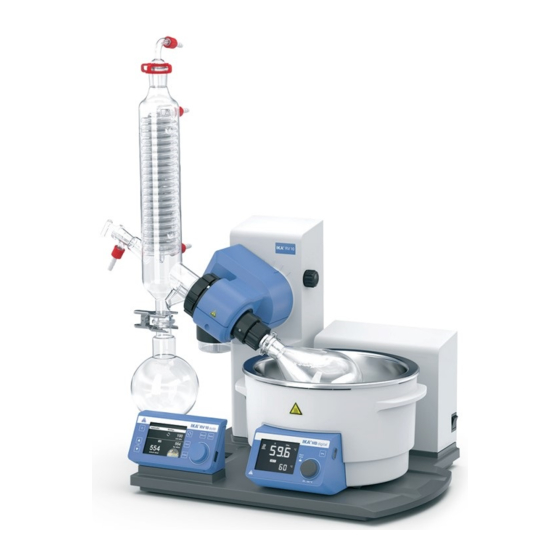
- Page 3 Geräteaufbau - Device setup Geräteaufbau - Device setup HB 10.2 Schermo di protezione (non compreso nella dotazione di fornitura) HB 10.1 Calotta di protezione (non compresa nella dotazione di fornitura) Bagno termostatico HB 10 Gruppo motore RV 10 auto Set di vetreria Supporto Flacone condensato Защитный...
- Page 4 Netzschalter "Power" switch Interrupteur Interruptor de Taste „Power" "Power" key Touche « Marche » alimentación Taste Liftposition „" Lift position "" key Touche de levage « » Tecla “Power” Taste Liftposition „" Lift position "" key Touche de levage « » (Alimentación) Drehzahltaste “Rotating speed”...
-
Page 5: Table Des Matières
2011/65/EU und mit den folgenden Normen und normativen Dokumenten übereinstimmt: EN 61010-1, EN 61010-2-051, EN 61326-1, EN 60529 und EN ISO 12100. Eine Kopie der vollständigen EU-Konformitätserklärung kann bei sales@ika.com angefordert werden. Zeichenerklärung (Extrem) Gefährliche Situation, bei der die Nichtbeachtung des Sicherheitshinweises zu Tod oder schwerer GEFAHR Verletzung führen kann. -
Page 6: Sicherheitshinweise
Sicherheitshinweise Zu Ihrem Schutz • Beachten Sie die Betriebsanleitung des Zubehörs z.B. • Lesen Sie die Betriebsanleitung vor Inbetriebnahme vollständig Vakuumpumpe, Heizbades. und beachten Sie die Sicherheitshinweise. • Verlegen Sie den druckseitigen Ausgang der Vakuumpumpe in • Bewahren Sie die Betriebsanleitung für Alle zugänglich auf. den Laborabzug. -
Page 7: Bestimmungsgemäße Verwendung
Drehzahlen. Große Unwuchtskräfte führen zum Bruch des Dampdurchführungsrohres! Bestimmungsgemäße Verwendung • Verwendung • Verwendungsgebiet Das Gerät ist in Verbindung mit dem von IKA empfohlenen Laborähnliche Umgebung im Innenbereich in Forschung, Lehre, Gewerbe oder Industrie. Zubehör geeignet für: - schnelle und schonende Destillation von Flüssigkeiten, Der Schutz für den Benutzer ist nicht mehr gewährleistet:... -
Page 8: Auspacken
RV 10 control V-C x x x x x x x x x x RV 10 control FLEX x x x x x x x x x x x RV 10 auto V... -
Page 9: Vakuum-Regelung
Mit dem Rotationsverdampfer RV 10 control können neben allen Mit dem Wasserfilter RV 10.5002 können Schmutzpartikel aus der manuellen sowie halbautomatischen Verdampfungsoperationen Wasserleitung vor der Ventiltechnik zurückgehalten werden. auch vollautomatische und mengengesteuerte Verdampfungs- Zur Druckreduzierung empfehlen wir das Druckregelventil prozesse gefahren werden. Dazu ist das Gerät standardmäßig mit RV 10.5003 direkt nach der Abnahmestelle in die Leitung zu set-... -
Page 10: Aufstellung
Aufstellung Antrieb RV 10 auto Transportsicherung lösen! Setzen Sie die Flasche ein und montieren Sie die mitgelieferten Schlauchanschlüsse an die Flasche VORSICHT Stellen Sie den Antrieb auf einen Winkel von ca. 30° • Halten Sie den Lift mit der Hand auf der Höhenposition und •... - Page 11 Heizbad Beachten Sie die Betriebsanleitung des VORSICHT Heizbades, Kapitel „Inbetriebnahme”! • Stellen Sie das Heizbad auf die Stellfläche des Rotationsantriebes und schieben sie es in die linke Position Hinweis: Der Datenaustausch zwischen Antriebseinheit und Heiz- bad findet mittels einer Infrarot- Schnittstelle (1) statt. Beachten Sie, dass die Kommunikation nur bei freier, nicht unterbrochener Lichtstrecke gewährleistet ist! Glassatz...
- Page 12 Erstinbetriebnahme • Dampfdurchführungsrohr einsetzen (1). • Dichtung einsetzen (2). Beachten Sie die Lage der Dichtung! • Überwurfmutter (3b) über den Flansch des Kühlers (3a) schie- ben. • Ringfeder (3c) ebenfalls über den Flansch des Kühlers (3a) schieben. • Kühlers (3a) auf die Dichtung (2) aufsetzen. •...
- Page 13 Montage Glassatz Hinweis: Beachten Sie die „Zeichnungen für die Montage des Glassatzes“ auf Seite 230. Pos. Bezeichnung Menge RV 10.1 RV 10.2 RV 10.3 RV 10.4 RV 10.5 RV 10.6 unbeschichtet unbeschichtet unbeschichtet unbeschichtet unbeschichtet unbeschichtet RV 10.10 beschichtet RV 10.20 beschichtet RV 10.30 beschichtet RV 10.40 beschichtet RV 10.50 beschichtet...
- Page 14 Verschlauchung RV 10.4002 RV 10.5001 Wasserventil Schlauchschelle Schlauchschelle Silikonschlauch optional) Vakuummagnetventil für Silikonschläuche für Vakuumschlauch (Innendurchm. 5 mm) Pos. 5, 6 & 7 Pos. 8 für Wasser Silikonschlauch (Innendurchm. 6 mm) Silikonschlauch (Innendurchm. 7 mm) Vakuumschlauch Verbindungsstück für Wasser für Wasser für Wasserventil RV 10.3_30 RV 10.5_50...
- Page 15 Sie die Schläuche. • Stecken Sie das Ventilanschlusskabel (RV 10.5001 oder RV 10.4002) in die vorgesehene Buchse. Schließen Sie die drehzahl- geregelte Vakuumpumpe an. Damit wechselt der RV 10 control automatisch in den Drehzahl-Vakuum-Regelbetrieb. • Schließen Sie den mitgelieferten Wasserablassschlauch durch Ste- cken des Nippels bis zum Anschlag in die Anschlussbuchse.
-
Page 16: Inbetriebnahme
Inbetriebnahme Arbeitsbildschirm im Auslieferzustand Nach dem Einschalten des Gerätes er- Danach wird automatisch im Display der Arbeitsbildschirm einge- scheint für einige Sekunden der Startbild- blendet. schirm. Es werden der Gerätename und die Software-Versionen angezeigt. Anschließend wird eine Information zum Download des Firmware Update Tools eingeblendet. - Page 17 Menüstruktur Werkseinstellung Verdampfer Modi Automatisch Heizbadmedium............Wasser Standardtemperatur............. 60 °C Manuell...................... 1013 mbar Pumpe %....................50% Volumen Lösemittel..............Acetic acid Ziel................100 ml Effizienz............... 80% Justierung..............- Programm....................- Lösemittel..............Acetic acid 100% Trocknenlauf............... - Starte nach... mm:ss............... 30:00 Reinigung Dauer mm:ss...............
- Page 18 Werkseinstellung Weitere Durchflussregelung................... Einstellungen Heizbadmedium..................Wasser Kühlerleistungsgrenze................900 w Max. Kühlerleistung................0 w Wert..........00:10 Rotation Intervall Intervallmodus Wert........00:10 Aktivieren..................- Grenzwerte Minimum..................5 rpm Maximum..................300 rpm Timerfunktion Timer Zeit hh:mm:ss............00:00:00 Signalton nach Ablauf..............- Aktivieren..................- Anzeige.............................
- Page 19 Werkseinstellung Service Belüftungsventil............- Ventile Vakuumventil............- Wasserventil............. - Pumpe......................... - Temperatureinstellung....................- Einstellungen Languages English................ Deutsch................- Français................- Español................- Italiano................- Português................. - Pусский язык..............- 中文................- 한국어................- 日本語................- Druck Einheiten mbar........ hPa..........
- Page 20 Menü (Details) 1. Verdampfer Reinigung Modi Starte nach...: Stellen Sie die Mindestzeit ein, die eine Messung Automatisch: In diesem Modus erkennt das System die tatsächli- laufen soll, bevor die Reinigung nach der Messung aktiviert wird. che Verdampfung durch Überprüfen der Temperaturdifferenz zwi- Der Reinigungsvorgang beginnt, wenn die Messung mindestens schen Wassereinlauf und -ablauf.
- Page 21 Hier kann man das zu destillierende Löse- Aktionen nach der Destillation mittel und seine Parameter (Bezeichnung, Formel, Heizbadtemperatur, Rotationsge- schw., Siedepunkt, Effizienz, Wärmeka- pazität, Entalpy, Dichte und i-Faktor) aus der Bibliothek auswählen. Die Temperatur, die effizienz und die Rotationsdrehzahl des Verdampferbads kann eingestellt werden.
- Page 22 4. Display In diesem Menü kann der Benutzer festlegen, welche Informa- tionen (Timer, Durchfluss, ΔT und/oder Kühlerleistung) auf dem Hauptbildschirm erscheinen sollen. 5. Programme Letzte Messung Speichern als: Speichern des Destillationsverlaufs als Programm. Bearb.: Zum Bearbeiten der gewählten Programmparameter. Mit dem Start-Stopp-Knopf auf „bearb.“ drücken, um mit der Be- arbeitung der ausgewählten Programmparameter zu beginnen.
- Page 23 Drehzahl bear- beiten Zeit bearbeiten Beispiel zur Speicherung der letzte Messung 6. Sicherheit Passworts ist es auf 0 0 0 zu setzen. Fortfahren nach Stromausfall Wenn diese Option aktiviert ist, wird die Messung nach einer Stromunterbrechung fortgeführt. Diese Option ist nur im Auto- matischen, 100 % oder Volumenmodus wählbar.
- Page 24 Hinweis: Verwenden Sie anderes Zubehör als das originale Zu- wendung von größeren Verdampferkolben (2 bzw. 3 Liter) bzw. behör von IKA, ist der Verschiebeweg des Heizbades von 50 mm je nach eingestelltem Winkel des Rotationsantriebs können Sie eventuell nicht mehr ausreichend, insbesondere beim Einsatz von das Heizbad um 50 mm nach rechts verschieben.
-
Page 25: Schnittstellen Und Ausgänge
Die NAMUR-Befehle und die zusätzlichen IKA- spezifischen Be- USB Geräte-Treiber: fehle dienen nur als Low Level Befehle zur Kommunikation zwi- Laden Sie zuerst den aktuellen Treiber für IKA-Geräte mit USB Schnittstelle unter http://www.ika.com/ika/lws/download/usb- schen Gerät und PC. Mit einem geeigneten Terminal bzw. Kom- driver.zip. -
Page 26: Wartung Und Reinigung
Stoffen sind. kontrolliert und gegebenenfalls ausgetauscht werden. Fordern Sie hierzu das Formular „Unbedenklichkeitserklärung“ bei IKA an oder verwenden Sie den download Ausdruck des For- Reinigung mulares auf der IKA Website www.ika.com. Senden Sie im Reparaturfall das Gerät in der Originalverpackung zu- •... - Page 27 Fehlermeldung Wirkung Ursache Korrekturmaßnahme Keine Druckände- Die Druckgradientenanalyse er- Die Pumpe läuft nicht. Den Anschluss des Pumpensteuerka- rung gibt keine Abweichung. bels prüfen. Die Energieversorgung der Pumpe prü- fen. Die Pumpe einschalten. Der Vakuumschlauch ist nicht ange- Den Anschluss des Vakuumschlauchs schlossen.
- Page 28 Schreiben Schreiben Lässt sich der Fehler durch die beschriebenen Maßnahmen nicht beseitigen oder bei einem anderen Fehler: - wenden Sie sich bitte an die IKA Serviceabteilung, - senden Sie das Gerät mit einer kurzen Fehlerbeschreibung ein. Gewährleistung Entsprechend den IKA - Verkaufs- und Lieferbedingungen beträgt Die Gewährleistung erstreckt sich nicht auf Verschleißteile und...
-
Page 29: Technische Daten
Technische Daten Betriebsspannungsbereich 100...240 ± 10% Nennspannung 100...240 Frequenz 50/60 Anschlussleistung ohne Heizbad Anschlussleistung im Stand by-Betrieb Drehzahl 0/5...300 Drehzahltoleranz ± 1(Sollwert Drehzahl < 100 rpm) ± 1(Sollwert Drehzahl ≥ 100 rpm) Drehzahlanzeige digital Display Abmessung Sichtbereich (B x H) 70 x 52 Anzeige TFT-Anzeige... -
Page 30: Eu Declaration Of Conformity
2011/65/EU and conforms with the following standards or normative documents: EN 61010-1, EN 61010-2-051, EN 61326-1, EN 60529 and EN ISO 12100. A copy of the complete EU Declaration of Conformity can be requested at sales@ika.com. Explication of warning symbols Indicates an imminently hazardous situation, which, if not avoided, will result in death, serious injury. -
Page 31: Safety Instructions
Safety instructions For your protection • Refer to the operating instructions for the accessories, e.g. • Read the operating instructions completely before starting up vacuum pump, heating bath. and follow the safety instructions. • Position the positive pressure outlet of the vacuum pump under •... -
Page 32: Intended Use
• Socket must be earthed (protective ground contact). If the safety lift does not work, please contact the IKA Service • Removable parts must be refitted to the appliance to prevent department. -
Page 33: Unpacking
RV 10 control V x x x x x x x x x x x x RV 10 control V-C x x x x x x x x x x x x RV 10 control FLEX x x x x x x x x x x x... -
Page 34: Vacuum Control
To do so, connect the vacuum to the minimum time difference from detection of the pressure pump (e.g. IKA Vacstar digital pump) to the port on the rear of value, the target value comparison for switching the vacuum valve the rotary evaporator. -
Page 35: Setting Up
Setting up Drive RV 10 auto Loosen transportation lock! Insert the bottle and attach the supplied hose connectors to the bottle CAUTION Set the drive at an angle of approx. 30° • Remove the clamping device for the angle setting of the rota- •... -
Page 36: Heating Bath
Heating bath Refer to the chapter “Commissioning“ CAUTION in the heating bath instruction manual! • Place the heating bath on the stand of the rotation drive and push it into the left position. Note: Data is exchanged between the drive unit and the heating bath by means of an infrared link (1). - Page 37 First use • Insert vapor tube (1). • Insert the vacuum seal (2). Pay attention to the correct positon of the vacuum seal! • Slide the union nut (3b) over the flange on the condenser (3a). • Also slide the annular spring (3c) over the flange on the con- denser (3a).
- Page 38 Mounting the glassware Note: Observe "Drawings for mounting the glassware" on page 230. Item Designation Quantity RV 10.1 non-coated RV 10.2 non-coated RV 10.3 non-coated RV 10.4 non-coated RV 10.5 non-coated RV 10.6 non-coated RV 10.10 coated RV 10.20 coated RV 10.30 coated RV 10.40 coated RV 10.50 coated...
- Page 39 Connect the pump's vacu- um inlet directly to the RV 10 pump hose connection. • Connect the pump controller cable to RV 10 control. Note: When connecting the ...
- Page 40 • Insert the valve connector cable (RV 10.5001, RV 10.4002) into the appropriate socket. Connect the speed-vacuum control pump. As a result, the RV 10 control automatically switches to normal speed-vacuum control operation. • Connect the water outlet hose (supplied) by pushing it onto the nipple until the stop inside the connection socket is reached.
-
Page 41: Commissioning
An information prompt then appears to download the IKA firmware update tool. Explanation of symbols on the working screen The symbols displayed change depending on the status and set- tings of RV 10 auto. -
Page 42: Menu Structure
Menu structure Factory settings Evaporator Modes Automatic Bath medium.............. Water Start temperature............60 °C Manual...................... 1013 mbar Pump %...................... 50% Volume Solvent............... Acetic acid Target................. 100 ml Efficiency..............80% Adjustment..............- Program..................... - Solvent..............Acetic acid 100% Drying................ - Start after... mm:ss............... - Page 43 Factory settings Flow control..................... Advanced Bath medium................... Water Cooler power limit..................900 w Max power of cooler................0 w Value..........00:10 Interval Rotation Interval mode Value........00:10 Activate................... - Speed limit Minimum..................5 rpm Maximum..................300 rpm Timer function Timer Time hh:mm:ss............
- Page 44 Factory settings Service Venting valve............- Valves Vacuum valve............- Water valve.............. - Pump........................... - Temperature adjustment....................- Settings Language English................ Deutsch................- Français................- Español................- Italiano................- Português................. - Pусский язык..............- 中文................- 한국어................- 日本語................- Pressure Units mbar........
- Page 45 Menu (details) 1. Evaporator Modes Duration: Set the duration of the cleaning process. Pump speed: The set pump speed in the cleaning menu is used to set the speed of the pump during the cleaning process. Higher speed causes partial vacuum in NOTICE the glassware if the system is closed.
- Page 46 Advanced Calculator Flow control: This setting can be deactivated in the manual mode It helps you to calculate the boiling point (vapor temperature) of if dry ice is used instead of a cooler. solvent, heating bath temperature and pressure. If one of the 3 Bath medium: Select either water or oil as the medium for the values has been defined, the other 2 values will be given.
- Page 47 5. Program Last measurement Save as: Save the distillation sequence as a program. Edit: Edit the selected program parameters. Start to edit the selected program parameters by pressing on menu option “Edit” with start/stop knob. The user can edit, insert or delete one selected program segment in the program.
- Page 48 Example of saving the last measurement 6. Safety Continue after power failure If this option is activated the measurement will continue after a break caused by a power failure. This option is only available in Automatic, 100 % and Volume mode. Activate: If tick is shown the option is activated.
- Page 49 Note: If non-original accessories are used that are not supplied • Move the lift to the bottom position and check the position by IKA, then it is possible that the 50 mm travel range provided of the heating bath in relation to the evaporation flask. When by the heating bath will not be sufficient.
-
Page 50: Interfaces And Outputs
PC. With a suitable terminal or commu- Install the driver by running the setup file. Then connect the IKA nication program these commands can be transmitted directly to device through the USB data cable to the PC. The data commu- the rotary evaporator. -
Page 51: Maintenance And Cleaning
• For cleaning disconnect the mains plug! If your appliance requires repair, return it in its original packaging. • Use only cleaning agents which have been approved by IKA to Storage packaging is not sufficient when sending the device - also clean IKA devices. -
Page 52: Error Messages
Error messages Any malfunctions during operation will be identified by an error message on the display. Once a serious error message has been displayed, the lift moves to the top end position and the device can no longer be operated. Proceed as follows in such cases: - switch off device using the mains switch, - carry out corrective measures,... -
Page 53: Warranty
- send the device for repair, including a short description of the fault. Warranty In accordance with IKA warranty conditions, the warranty period The warranty does not cover worn out parts, nor does it apply is 24 months. For claims under the warranty please contact to faults resulting from improper use, insufficient care or your local dealer. -
Page 54: Technical Data
Technical Data Operating voltage range 100...240 ± 10% Rated voltage 100...240 Frequency 50/60 Power input without heating bath Power input operation “standby” Speed 0/5...300 Speed tolerance ± 1(Set speed < 100 rpm) ± 1(Set speed ≥ 100 rpm) Speed display digital Dimensions of visible display area (W x H) 70 x 52... -
Page 55: Déclaration Ue De Conformité
2006/42/CE, 2014/30/UE et 2011/65/UE, ainsi qu‘aux normes et documents normatifs suivants: EN 61010-1, EN 61010-2-051, EN 61326-1, EN 60529 et EN ISO 12100. Une copie de la déclaration UE de conformité complète peut être demandée en adressant un courriel à l'adresse sales@ika.com. Explication des symboles Situation (extrêmement) dangereuse dans laquelle le non-respect des consignes de sécurité... -
Page 56: Consignes De Sécurité
Consignes de sécurité Pour votre protection • Respectez le mode d'emploi des accessoires, par ex. de la • Lire entièrement le mode d'emploi avant la mise en service et pompe à vide, du bain chauffant. respecter les consignes de sécurité. •... -
Page 57: Le Dispositif De Levage De Sécurité Doit Être Contrôlé
• La prise doit être mise à la terre (contact à conducteur de Si le dispositif de levage de sécurité ne fonctionne pas, veuillez protection). contacter le service après-vente IKA. • Les pièces démontables de l‘appareil doivent être reposées sur Concernant l‘évaporateur (ballon d‘évaporation plus contenu), le l‘appareil pour empêcher la pénétration de corps étrangers, de... -
Page 58: Déballage
RV 10 control V x x x x x x x x x x x x RV 10 control V-C x x x x x x x x x x x x RV 10 control FLEX x x x x x x x x x x x... -
Page 59: Régulation Du Vide
RV10.4002 n'est pas nécessaire et ne doit pas être est fermée. En raison du délai minimal entre la détection de la raccordée ! Pour cela, raccorder la pompe à vide (p. ex. IKA Vacstar valeur de pression et la comparaison avec la valeur théorique pour digital pump) au raccord situé... -
Page 60: Installation
Installation Entraînement RV 10 auto Desserrez la sécurité de transport Placez le flacon et montez les raccords de flexibles fournis sur le flacon PRUDENCE Positionnez l'entraînement avec un angle d'env. 30° • Desserrez le dispositif de serrage pour régler l'angle de •... -
Page 61: Bain Chauffant
Bain chauffant Suivez le mode d'emploi du bain chauf- PRUDENCE fant, chapitre "Mise en service" ! • Placez le bain chauffant sur la surface d'appui de l'entraînement de rotation et poussez-le en position gauche. Remarque : l'échange de données entre l'unité d'entraînement et le bain chauffant se fait à... - Page 62 Avant la mise en service • Montez le conduit de vapour (1). • Montez le joint (2). Attention à la position du joint d'étanchéité ! • Poussez l'écrou d'accouplement (3b) sur la bride du refroidis- seur (3a). • Poussez également le ressort-bague (3c) sur la bride du refroi- disseur (3a).
- Page 63 Montage de la verrerie Remarque : Respectez les « Dessins pour le montage de la verrerie » à la page 230. Pos. Désignation Quantité RV 10.1 RV 10.2 RV 10.3 RV 10.4 RV 10.5 RV 10.6 sans revêtement sans revêtement sans revêtement sans revêtement sans revêtement...
- Page 64 Système flexible RV 10.4002 RV 10.5001 Vanne d'eau Collier Collier Flexible en silicone option) Électrovanne à vide pour flexible en silicone pour flexible de vide (diamètre int. 5 mm) Rep. 5, 6 et 7 Rep. 8 pour l'eau Flexible en silicone Flexible en silicone Flexible de vide Raccord pour vanne d'eau...
- Page 65 • Branchez le câble de raccordement de vanne (RV 10.5001 ou RV 10.4002) dans la prise prévue à cet effet. Raccordez la pompe à vide à vitesse de rotation variable. Ainsi, le RV 10 control passe automatiquement au mode de régulation du vide en fonction de la vitesse de rotation.
-
Page 66: Mise En Service
Mise en service État de l'écran de travail à la livraison Après la mise en marche de l'appareil, L'écran de travail s'affiche ensuite automatiquement. l'écran d'accueil s'affiche pendant quel- ques secondes. Le nom de l'appareil et les versions des logiciel s'affichent. Apparaît ensuite une information sur le téléchargement des outils de mise à... - Page 67 Structure des menus Réglage d'usine Evaporator Modes Automatic Bath medium.............. Water Start temperature............60 °C Manual...................... 1013 mbar Pump %...................... 50% Volume Solvent............... Acetic acid Target................. 100 ml Efficiency..............80% Adjustment..............- Program..................... - Solvent..............Acetic acid 100% Drying................ - Start after...
-
Page 68: Réglage D'usine
Réglage d'usine Flow control..................... Advanced Bath medium................... Water Cooler power limit..................900 w Max power of cooler................0 w Value..........00:10 Interval Rotation Interval mode Value........00:10 Activate................... - Speed limit Minimum..................5 rpm Maximum..................300 rpm Timer function Timer Time hh:mm:ss............ - Page 69 Réglage d'usine Service Venting valve............- Valves Vacuum valve............- Water valve.............. - Pump........................... - Temperature adjustment....................- Settings Language English................ Deutsch................- Français................- Español................- Italiano................- Português................. - Pусский язык..............- 中文................- 한국어................- 日本語................- Pressure Units mbar........
- Page 70 Menu (détails) 1. Evaporator (Évaporateur) Modes Duration (Durée) : Réglage de la durée de l'opération de nettoyage. Pump speed (Vitesse de la pompe) : La vitesse de rotation de la pompe dans le menu Nettoyage sert à régler la vitesse de rotation de la pompe pendant l'opération de nettoyage.
- Page 71 Advanced (Autres réglages) Name and formula (Désignation et formule) : La désignation et la formule permettent d'identifier le solvant. Calculator (Calculateur) Flow control (Réglage du débit) : Ce réglage peut être désactivé en mode manuel si de la neige carbonique est utilisée à la place d'un refroidisseur.
- Page 72 5. Program (Programme) Dernière mesure Save as (Enregistrer sous) : Enregistrement du processus de dis- tillation en tant que programme. Edit (Modifier) : Permet de modifier les paramètres de program- me sélectionnés. Validez « Edit » (modifier) en appuyant sur le bouton de démar- Program 1 - 10 (Programme 1 à...
- Page 73 Modifier la durée Exemple d'enregistrement de la dernière mesure 6. Safety (Sécurité) fonction, définir le mot de passe 0 0 0. Continue after power failure (Reprise après une panne de courant) Si cette option est activée, la mesure reprend après une interrupti- on en raison d'une coupure de courant.
-
Page 74: Installation Du Bain Chauffant
• Remplissez le bain chauffant d‘agent de mise à température Utilisez la plaque IKA RV 10.3000 pour étendre la course de dé- jusqu‘à ce que le ballon d‘évaporation soit immergé aux 2/3. placement du bain chauffant de 150 mm. -
Page 75: Interfaces Et Sorties
Labworldsoft est un et installer les pilotes en exécutant le fichier d’installation. Ensuite, relier l'appareil IKA au PC au moyen du câble USB. La communi- pack logiciel IKA convivial sous MS Windows pour la commande cation des données se fait via un port COM virtuel. -
Page 76: Entretien Et Nettoyage
Le joint d'étanchéité du condenseur en verre doit être contrôlé à Demander pour ce faire le formulaire « Certificat de décon- intervalle régulier et remplacé si nécessaire. tamination » auprès d’IKA ou télécharger le formulaire sur le site d’IKA à l’adresse www.ika.com et l’imprimer. Nettoyage Si une réparation est nécessaire, expédier l’appareil dans son em-... -
Page 77: Message D'erreur
Message d'erreur Conséquence Cause Mesure corrective Aucune modification L'analyse des gradients de pressi- La pompe ne tourne pas. Contrôler le raccordement du câble de de la pression on n'indique aucun écart. commande de la pompe. Contrôler l'alimentation électrique de la pompe. -
Page 78: Garantie
- expédier l'appareil avec une brève description de l'erreur. Garantie Selon les conditions générales de vente d'IKA, la garantie a une La garantie ne s'étend pas aux pièces d'usure et n'est pas valable durée de 24 mois. En cas de demande de garantie, s'adresser au pour les erreurs causées par une manipulation non conforme, un... -
Page 79: Caractéristiques Techniques
Caractéristiques techniques Plage de tension de service 100...240 ± 10% Tension nominale 100...240 Fréquence 50/60 Puissance absorbée sans bain chauffant Puissance absorbée en mode d’opération “stand by” Vitesse de rotation 0/5...300 Tolérance de vitesse ± 1(Vitesse cible < 100 rpm) ±... -
Page 80: Declaración Ue De Conformidad
EN 61326-1, EN 60529 y EN ISO 12100. Si lo desea, puede solicitar una copia completa de la declaración de conformidad de la UE en la dirección de correo electrónico sales@ ika.com. Explicación de símbolos Situación (extremadamente) peligrosa en la que la no observación de las advertencias de seguridad puede PELIGRO provocar la muerte o una lesión grave. -
Page 81: Advertencias De Seguridad
Advertencias de seguridad Para su protección • La seguridad del funcionamiento solo está garantizada si se • Lea por completo las instrucciones de uso antes de poner en utilizan los accesorios descritos en el Capítulo “Accesorios”. servicio el aparato y observe las advertencias de seguridad. •... -
Page 82: Uso Previsto
• La caja de enchufe utilizada debe estar puesta a tierra (contacto de conductor protector). en contacto con el departamento de servicio técnico de IKA. En el lado del evaporador (matraz de evaporación más contenido) el • Las piezas extraíbles del aparato deben volver a incorporarse peso máximo permitido es de 3,0 kg. -
Page 83: Informaciones Importantes
RV 10 control V x x x x x x x x x x x x RV 10 control V-C x x x x x x x x x x x x RV 10 control FLEX x x x x x x x x x x x... - Page 84 RV 10 control (para vacío): La regulación de vacío externa de Si utiliza el equipo con agua corriente recomendamos usar la vál- dos polos también está...
- Page 85 Instalación Accionamiento RV 10 auto Quite el dispositivo de protección para el transporte Coloque la botella y monte en la misma las conexiones de mangueras incluidas en el volumen de suministro PRECAUCIÓN Ajuste el accionamiento a un ángulo de aprox. 30° •...
-
Page 86: Baño Calefactor
Baño calefactor Observe las instrucciones de uso del PRECAUCIÓN baño calefactor y, sobre todo, el capí- tulo relativo a la puesta en marcha. • Coloque el baño calefactor en la superficie de ajuste del accion- amiento de rotación y desplácelo a la posición izquierda. Nota: El intercambio de datos entre la unidad de accionamiento y el baño calefactor se realiza mediante una interfaz de infrarrojos (1). - Page 87 Ante puesta en servizio • Monte el tubo de paso del vapor (1). • Monte la junta (2). Observe la posición de la junta. • Desplace la tuerca de racor (3b) a través de la brida del refrige- rador (3a). •...
- Page 88 Montaje del equipo de vidrio Nota: Observe las indicaciones del apartado “Planos para el montaje del equipo de vidrio”, incluido en la página 230. Pos. Designación Cantidad RV 10.1 no recubierto RV 10.2 no recubierto RV 10.3 no recubierto RV 10.4 no recubierto RV 10.5 no recubierto RV 10.6 no recu- RV 10.10 recubierto...
- Page 89 RV 10.6_60 Nota: Observe las indicaciones del apartado “Planos para la conexión de las mangueras”, incluido en la página 232. Operación RV 10 control Operación RV 10 auto • Coloque la válvula de vacío RV 10.4002 en el soporte previsto a •...
- Page 90 • Conecte el cable de conexión de las válvulas (RV 10.5001 o RV 10.4002) a la toma prevista a tal efecto. Conecte la bomba de vacío regulada por velocidad. De este modo, el RV 10 control cambia automáticamente a la regulación de vacío por velocidad.
-
Page 91: Puesta En Servicio
A continuación, aparece un mensaje in- formativo para descargar la herramienta de actualización de firmware de IKA. Explicación de símbolos de la pantalla de trabajo Los símbolos mostrados cambian en función del estado y de los ajustes del RV 10 auto. -
Page 92: Estructura Del Menú
Estructura del menú Configuración de fábrica Evaporator Modes Automatic Bath medium.............. Water Start temperature............60 °C Manual...................... 1013 mbar Pump %...................... 50% Volume Solvent............... Acetic acid Target................. 100 ml Efficiency..............80% Adjustment..............- Program..................... - Solvent..............Acetic acid 100% Drying................ - Start after... -
Page 93: Bath Medium
Configuración de fábrica Flow control..................... Advanced Bath medium................... Water Cooler power limit..................900 w Max power of cooler................0 w Value..........00:10 Interval Rotation Interval mode Value........00:10 Activate................... - Speed limit Minimum..................5 rpm Maximum..................300 rpm Timer function Timer Time hh:mm:ss............ - Page 94 Configuración de fábrica Service Venting valve............- Valves Vacuum valve............- Water valve.............. - Pump........................... - Temperature adjustment....................- Settings Language English................ Deutsch................- Français................- Español................- Italiano................- Português................. - Pусский язык..............- 中文................- 한국어................- 日本語................
-
Page 95: Start After
Detalles del área Menu (Menú) 1. Evaporator (Evaporador) Modes (Modos) do la medición ha transcurrido durante al menos el tiempo ajustado. Duration (Duración): Configure aquí la duración del proceso de limpieza. Pump speed (Velocidad de la bomba): El régimen de revolucio- nes configurado para la bomba sirve para definir la velocidad de la bomba durante el proceso de limpieza. - Page 96 Advanced (Opciones avanzadas) superior de la biblioteca de disolventes. Name and formula (Denominación y fórmula): La denominaci- ón y la fórmula permiten identificar el disolvente. Calculator (Calculadora) Flow control (Control del caudal): Esta configuración puede desactivarse en el modo manual cuando, en lugar de un refrigera- dor, se utiliza hielo seco.
- Page 97 5. Programs (Programas) Última medición Save as (Guardar como): Permite guardar el proceso de destila- ción como programa. edit (editar): Permite editar los parámetros del programa selec- cionado. Utilice el botón de inicio y parada para pulsar “edit” (editar) y, de este modo, iniciar la edición de los parámetros del Program 1 –...
- Page 98 Editar tiempo Ejemplo de cómo guardar la última medición 6. Safety (Seguridad) Continue after power failure (Continuar después de un corte de corriente) Si esta opción está activada, la medición continúa después de un corte en la corriente. Esta opción solo puede seleccionarse en el modo automático, el modo 100 % o el modo de volumen.
- Page 99 • Llene el baño calefactor con fluido de atemperado hasta que el antiespumantes. matraz de atemperado esté rodeado de fluido de atemperado Utilice la placa de montaje IKA RV 10.3000 para ampliar el recor- hasta 2/3 de su volumen. rido de desplazamiento del baño calefactor en 150 mm.
-
Page 100: Interfaces Y Salidas
Labworldsoft es un cómodo cutando el archivo de instalación. Acto seguido, conecte el aparato paquete de software de IKA que se utiliza en el sistema de MS Win- IKA al PC a través del cable de datos USB. La comunicación de datos dows para controlar el aparato y para recopilar los datos del mismo;... -
Page 101: Mantenimiento Y Limpieza
La junta del refrigerador de vidrio debe revisarse y, en su caso, Solicite a tal fin el formulario “Certificado de descontami- cambiarse a intervalos periódicos. nación” a IKA, o descargue el formulario en la página web de IKA, ubicada en la dirección www.ika.com. Limpieza Devuelva el aparato que requiere reparación en su embalaje origi-... - Page 102 Mensaje de error Efecto Causa Medida correctiva No se produce un cam- El análisis del gradiente de presi- La bomba no funciona. Revise la conexión del cable de control de bio en la presión. ón no obtiene ninguna divergen- la bomba. cia.
- Page 103 - Envíe el aparato a reparación con una breve descripción del fallo. Garantía Según las condiciones de compra y suministro de IKA, la garantía La garantía no se aplica a piezas de desgaste ni tampoco a errores tiene una duración total de 24 meses. Si se produce un caso de que tengan su causa en un manejo inadecuado o en un cuidado garantía, póngase en contacto con su proveedor, o envíe el...
-
Page 104: Datos Técnicos
Datos técnicos Intervalo de tensión de servicio 100...240 ± 10% Tensión nominal 100...240 Frecuencia 50/60 Rendimiento de la conexión sin baño calefactor Rendimiento de la conexión en funcionamiento “stand by” Velocidad 0/5...300 Tolerancia de velocidad ± 1(valor nominal de velocidad < 100 rpm) ±... -
Page 105: Dichiarazione Di Conformità Ue
2014/30/UE e 2011/65/UE ed è conforme alle seguenti norme e ai seguenti documenti normativi: EN 61010-1, EN 61010-2-051, EN 61326-1, EN 60529 e EN ISO 12100-1. Una copia della dichiarazione di conformità UE completa può essere richiesta all'indirizzo sales@ika.com. Spiegazione dei simboli Situazione (estremamente) pericolosa in cui la mancata osservanza dell’avvertenza per la sicurezza può... -
Page 106: Avvertenze Per La Sicurezza
Avvertenze per la sicurezza Per la Vostra sicurezza • Posizionare l'apertura lato pressione della pompa del vuoto in • Leggere accuratamente le istruzioni per l'uso prima della messa una cappa. in funzione e attenersi alle avvertenze per la sicurezza. • Utilizzare l'apparecchio soltanto in presenza di uno sfiatatoio •... -
Page 107: Uso Conforme
Uso conforme • Utilizzo • Ambito di utilizzo Ambienti interni simili all‘ambiente di laboratorio dei settori di L'apparecchio, abbinato agli accessori consigliati da IKA, è ricerca, formazione, commercio o industria. idoneo alle seguenti funzioni: - distillazione rapida e delicata di liquidi, La sicurezza dell'utente non è... - Page 108 RV 10 control V x x x x x x x x x x x x RV 10 control V-C x x x x x x x x x x x x RV 10 control FLEX x x x x x x x x x x x...
-
Page 109: Regolazione Del Vuoto
RV 10.4002 non è necessaria e non può essere collegata! a partire dal rilevamento del valore di pressione, della compensa- Collegare a tale scopo la pompa per vuoto (per es. la pompa IKA zione del valore nominale per il collegamento di una valvola del Vacstar digital) all'interfaccia sul retro dell'evaporatore rotante. - Page 110 Installazione Gruppo motore RV 10 auto Allentare lo staffaggio di sicurezza per il trasporto! Inserire la bottiglia e montare su quest'ultima i raccordi dei tubi flessibili forniti in dotazione CAUTELA Impostare il gruppo motore su un angolo di ca. 30° •...
- Page 111 Bagno termostatico Attenersi alle istruzioni per l'uso del ba- CAUTELA gno termostatico, vedi capitolo “Messa in funzione”! • Collocare il bagno termostatico sulla superficie d'impiego dell'attuatore rotativo e spingerlo in posizione sinistra. Nota: Lo scambio dati tra l'unità motrice e il bagno termostatico avviene mediante un'interfaccia a infrarossi (1).
- Page 112 Prima messa in funzione • Inserire il tubo del vapore (1). • Inserire la guarnizione (2). Rispettare la posizione della guarnizi- one! • Infilare il dado a risvolto (3b) sulla flangia del condensatore ref- rigerato (3a). • Infilare anche la molla anulare (3c) sulla flangia del condensato- re refrigerato (3a).
- Page 113 Montaggio del set di vetreria Nota: Rispettare i "Disegni per il montaggio del set di vetreria" a pagina 230. Pos. Denominazione Quantità RV 10.1 non rivestito RV 10.2 non rivestito RV 10.3 non rivestito RV 10.4 non rivestito RV 10.5 non rivestito RV 10.6 non RV 10.10 rivestito RV 10.20 rivestito...
- Page 114 RV 10.1_10 RV 10.6_60 Nota: Rispettare i "Disegni per il collegamento dei tubi flessibili" a pagina 232. Operazione di RV 10 control Operazione di RV 10 auto • Montare la valvola del vuoto RV 10.4002 nell'apposito suppor- • Per il normale funzionamento con vuoto con pompa per vuoto to previsto e collegare il tubo flessibile del vuoto alla valvola.
- Page 115 • Inserire il cavo di collegamento della valvola (RV 10.5001 o RV 10.4002) nella presa prevista. Collegare la pompa per vuoto a controllo di velocità. RV 10 control passa automaticamente alla modalità di regolazione del vuoto a controllo di velocità.
-
Page 116: Messa In Funzione
Messa in funzione Schermata di lavoro all'atto della fornitura Dopo l'accensione dell'apparecchio, Quindi il display mostra automaticamente la schermata di lavoro. per alcuni secondi compare la scherma- ta di avvio. Vengono visualizzati il nome dell'apparecchio e le versioni software. Successivamente compare un'informazione per il download del Firmware Update Tool. -
Page 117: Struttura Del Menu
Struttura del menu Impostazioni di fabbrica Evaporator Modes Automatic Bath medium.............. Water Start temperature............60 °C Manual...................... 1013 mbar Pump %...................... 50% Volume Solvent............... Acetic acid Target................. 100 ml Efficiency..............80% Adjustment..............- Program..................... - Solvent..............Acetic acid 100% Drying................ - Start after... -
Page 118: Mm:ss
Impostazioni di fabbrica Flow control..................... Advanced Bath medium................... Water Cooler power limit..................900 w Max power of cooler................0 w Value..........00:10 Interval Rotation Interval mode Value........00:10 Activate................... - Speed limit Minimum..................5 rpm Maximum..................300 rpm Timer function Timer Time hh:mm:ss............ - Page 119 Impostazioni di fabbrica Service Venting valve............- Valves Vacuum valve............- Water valve.............. - Pump........................... - Temperature adjustment....................- Settings Language English................ Deutsch................- Français................- Español................- Italiano................- Português................. - Pусский язык..............- 中文................- 한국어................- 日本語................
-
Page 120: Program
Menu (dettagli) 1. Evaporator (Evaporatore) Modes (Modalità) attivata la pulizia dopo la misurazione. Il processo di pulizia ha inizio quando la misurazione ha avuto luogo almeno per il tempo impostato. Duration (Durata): Impostazione della durata del processo di pu- lizia. Pump speed (Velocità... - Page 121 Advanced (Altre impostazioni) solventi specifici dell'utente. I solventi specifici dell'utente sono vi- sualizzati in arancione e si trovano in alto nella libreria dei solventi. Name and formula (Denominazione e formula): Il solvente può essere identificato mediante la denominazione e la formula. Calculator (Calcolatore) Flow control (Regolazione del flusso): Questa impostazione può...
- Page 122 5. Programs (Programmi) come programma. Edit (Modifica): ): Per la modifica dei parametri del programma selezionati. Con il pulsante Start/Stop premere "Edit" per avviare la modifica dei parametri del programma selezionati. L'utente può modificare, cancellare, aggiungere o salvare nel programma un segmento selezionato.
- Page 123 Modifica tempo Esempio di salvataggio dell'ultima misurazione 6. Safety (Sicurezza) Continue after power failure (Continua dopo interruzione di cor- rente) Se questa opzione è attiva, la misurazione viene proseguita dopo un'interruzione di corrente. Questa opzione è selezionabile solo in modalità Automatic, 100% o Volume. Activate (Attiva): Un segno di spunta indica che l'opzione è...
- Page 124 Nota: Se si utilizzano accessori diversi dagli accessori originali di lizzando recipienti di evaporazione piuttosto grandi (da 2 o 3 IKA, la corsa di spostamento di 50 mm del bagno termostatico litri), a seconda dell'angolo impostato per l'attuatore rotativo, è...
-
Page 125: Interfacce E Uscite
USB dal sito Internet: mandi all’apparecchio. Labworldsoft è un pratico pacchetto soft- http://www.ika.com/ika/lws/download/usb-driver.zip. ware di IKA in MS Windows per il comando dell’apparecchio e la e installarlo eseguendo il file Setup. Successivamente collegare rilevazione dei suoi dati, il quale consente anche degli inserimenti l’apparecchio IKA al PC mediante il cavo dati USB. -
Page 126: Manutenzione E Pulizia
La guarnizione del condensatore refrigerato in vetro deve essere Allo scopo richiedere il modulo “Decontamination Certificate“ controllata a intervalli regolari ed eventualmente sostituita. a IKA oppure utilizzare il modulo stampato e scaricato dal sito web di IKA www.ika.com. Pulizia In caso di riparazione, rispedire l‘apparecchio nel suo imballo •... - Page 127 Messaggio di errore Conseguenza Causa Misura correttiva Nessuna modifica alla L'analisi del gradiente della pres- La pompa non funziona. Controllare il collegamento del cavo di co- pressione sione non rileva alcuna deviazio- mando della pompa. Controllare l'alimentazione di energia della pompa.
- Page 128 - spedire l'apparecchio con una breve descrizione dell'errore. Garanzia In base alle condizioni di vendita e di fornitura IKA la garanzia La garanzia non copre le parti soggette a usura e non vale in caso ha una durata di 24 mesi. In caso di garanzia rivolgersi al proprio di anomalie riconducibili a una movimentazione impropria e a una rivenditore specializzato oppure inviare l’apparecchio direttamente...
-
Page 129: Dati Tecnici
Dati tecnici Intervallo tensione di esercizio 100...240 ± 10% Tensione nominale 100...240 Frequenza 50/60 Potenza elettrica installata senza bagno termostatico Potenza elettrica installata in modalità standby Velocità 0/5...300 Tolleranza numero di giri ± 1(valore nominale velocità < 100 rpm) ± 1(valore nominale velocità ≥ 100 rpm) Indicatore di velocità... - Page 130 EC, 2014/30/EC и 2011/65/EC и отвечает стандартам или стандартизованным документам EN 61010-1, EN 61010-2-051, EN 61326-1, EN 60529 и EN ISO 12100. Копию полного заявления о соответствии требованиям стандартов ЕС можно запросить по адресу sales@ika.com. Условные обозначения (Крайне) опасная ситуация, в которой несоблюдение данного указания по технике безопасности...
-
Page 131: Указания По Технике Безопасности
Указания по технике безопасности В целях защиты персонала • Устройство не подходит для ручного управления (кроме • Перед вводом в эксплуатацию полностью прочитайте руко- лифта движения). водство по эксплуатации и примите во внимание указания • Безопасность работы гарантируется только при использовании по... - Page 132 указанным на шильдике устройства. посредством нажатия функциональных кнопок подъемника. • Розетка электрической сети должна иметь заземляющий Если устройство аварийного подъема не функционирует, контакт. обратитесь в сервисную службу компании IKA. • Съемные детали следует устанавливать обратно на Со стороны испарителя (испарительная...
-
Page 133: Полезная Информация
RV 10 control V x x x x x x x x x x x x RV 10 control V-C x x x x x x x x x x x x RV 10 control FLEX x x x x x x x x x x x... - Page 134 С помощью ротационного испарителя RV 10 control наряду С помощью фильтра для воды RV 10.5002 можно предотвратить со всеми ручными и полуавтоматическими операциями попадание частиц грязи из водопровода в клапанный механизм. испарения также можно выполнять полностью автоматические Для уменьшения давления мы рекомендуем установить в...
- Page 135 Размещение Привод RV 10 auto Открутите транспортировочное крепление Вставьте склянку и смонтируйте входящие в комплект поставки штуцеры для подключения шлангов на склянке ОСТОРОЖНО Установите привод на угол прим. 30° • Держите подъемник одной рукой на высоте и удалите винт • Открутите зажимное приспособление для регулировки с...
- Page 136 Нагревательная баня Соблюдайте инструкцию по ОСТОРОЖНО эксплуатации нагревательной бани, глава «Ввод в эксплуатацию»! • Установите нагревательную баню на место для установки ротационного привода и сдвиньте ее влево. Примечание: обмен данными между узлом привода и нагревательной баней осуществляется при помощи инфракрасного интерфейса (1). Учитывайте, что обмен данными...
- Page 137 Первый ввод в эксплуатацию • Вставьте паропроводную трубку (1). • Вставьте уплотнение (2). Следите за положением уплотнения! • Установите накидную гайку (3b) на фланец охладителя (3a). • Также установите пружинное кольцо (3c) на фланец охладителя (3a). • Установите охладитель (3a) на уплотнение (2). •...
- Page 138 Монтаж стеклянной посуды Примечание: см. чертежи для монтажа стеклянной посуды на стр. 230. Поз. Наименование Количество RV 10.1 Номера с RV 10.2 Номера с RV 10.3 Номера с RV 10.4 Номера с RV 10.5 Номера с RV 10.6 Номера с покрытием...
- Page 139 Система шлангов RV 10.5001 Водяной клапан RV10.4002 Вакуумный Хомут для силиконового Хомут для вакуумного Силиконовый шланг (опция) магнитный клапан шланга шланга (внутренний диаметр 5 мм) Поз. 5, 6 и 7 Поз. 8 для воды Силиконовый шланг Силиконовый шланг Вакуумный шланг Соединительный...
- Page 140 • Вставьте соединительный кабель для клапана (RV 10.5001 или RV 10.4002) в соответствующий разъем. Подключите вакуумный насос с регулированием частоты вращения. При этом испаритель RV 10 control автоматически переключается в режим регулирования вакуума посредством регулирования частоты вращения. • Подсоедините входящий в комплект поставки шланг для слива...
- Page 141 Ввод в эксплуатацию Рабочий экран на момент поставки После включения прибора в течение Затем на дисплее автоматически появляется рабочий экран. нескольких секунд отображается экран приветствия. Отображаются название устройства и версия программного обеспечения. Затем на дисплее появляется информация по скачиванию Firmware Update Tool.
-
Page 142: Структура Меню
Структура меню Заводская настройка Evaporator Modes Automatic Bath medium.............. Water Start temperature............60 °C Manual...................... 1013 mbar Pump %...................... 50% Volume Solvent............... Acetic acid Target................. 100 ml Efficiency..............80% Adjustment..............- Program..................... - Solvent..............Acetic acid 100% Drying................ - Start after... mm:ss............... -
Page 143: Mm:ss
Заводская настройка Flow control..................... Advanced Bath medium................... Water Cooler power limit..................900 w Max power of cooler................0 w Value..........00:10 Interval Rotation Interval mode Value........00:10 Activate................... - Speed limit Minimum..................5 rpm Maximum..................300 rpm Timer function Timer Time hh:mm:ss............ - Page 144 Заводская настройка Service Venting valve............- Valves Vacuum valve............- Water valve.............. - Pump........................... - Temperature adjustment....................- Settings Language English................ Deutsch................- Français................- Español................- Italiano................- Português................. - Pусский язык..............- 中文................- 한국어................- 日本語................- Pressure Units mbar........
-
Page 145: Pump Speed
Меню (подробное описание) 1. Evaporator (испаритель) Modes (режимы) Start after... (запуск через...): установите минимальное время, в течение которого должно выполняться измерение, прежде чем активируется очистка после измерения. Процесс очистки начинается, если измерение выполнялось как минимум в течение заданного времени. Duration (продолжительность): установка... - Page 146 Можно задать действия, которые будут выполняться после i-коэффициент) из библиотеки. Температуру, КПД и частоту завершения измерения (вручную или автоматически). вращения бани испарителя можно регулировать. В список растворителей можно добавить до пяти новых Advanced (дополнительные настройки) растворителей, заданных пользователем. Растворители, заданные пользователем, отображаются оранжевым цветом и...
- Page 147 5. Program (программы) Last measurement (Последнее измерение) Save as (сохранить как): сохранение хода процесса дистилляции как программы. Edit (редактировать): используется для редактирования параметров выбранной программы. Нажмите кнопку «Пуск/останов» на функции «Редактировать», Program 1 - 10 (Программа 1—10) чтобы начать редактирование параметров выбранной В...
- Page 148 Редактировать время Пример сохранения последнего измерения 6. Safety (безопасность) Continue after power failure (продолжение после исчезновения питания) Если эта функция активирована, измерение продолжается после исчезновения питания. Эту функцию можно выбрать в автоматическом режиме, в режиме 100% или «Объем». Activate (активировать): галочка означает, что эта функция активирована.
- Page 149 закалочной средой до тех пор, пока испарительная колба объемом 3 л и пеногасителя. не будет окружена закалочной средой на 2/3 своего Используйте навесную пластину IKA RV 10.3000 для объема. увеличения диапазона смещения нагревательной бани на • Включите привод вращения и медленно увеличьте...
-
Page 150: Интерфейсы И Выходы
и установите драйвер, запустив файл Setup. Затем соедините на аппарат. Labworldsoft — это удобный пакет программ IKA, аппарат IKA с ПК с помощью кабеля данных USB. Обмен работающих в среде MS Windows и предназначенных для управления данными осуществляется через виртуальный COM-порт. -
Page 151: Техническое Обслуживание И Очистка
Аппараты принимаются в ремонт только после очистки и чески закономерной частотой. удаления опасных веществ. Уплотнение охладителя для стекла необходимо регулярно Запросите формуляр „Decontamination Certificate“ в проверять и при необходимости заменять. компании IKA или загрузите его с сайта IKA www.ika.com и распечатайте. Очистка Отправляйте аппараты на... - Page 152 Сообщение об Последствие Причина Меры по устранению ошибке Изменение давления Анализ градиента давления не Насос не работает. Проверьте подключение кабеля отсутствует выявил отклонений. управления насоса. Проверьте электропитание насоса. Включите насос. Вакуумный шланг не Проверьте подключение вакуумного подключен. шланга (насос, резервуар). Кабель...
- Page 153 Гарантия В соответствии с условиями продажи и поставки компании Гарантия не распространяется на изнашивающиеся детали, IKA срок гарантии составляет 24 месяца. При наступлении случаи ненадлежащего обращения, недостаточного ухода и гарантийного случая просим обращаться к продавцу или обслуживания, не соответствующих указаниям настоящего...
- Page 154 Технические данные Диапазон рабочего напряжения 100...240 ± 10% Номинальное напряжение 100...240 Частота 50/60 Присоединяемая мощность без нагревательной бани Присоединяемая мощность в режиме ожидания Скорость вращения 0/5...300 Скорость толерантности ± 1(заданная скорость < 100 rpm) ± 1(заданная скорость ≥ 100 rpm) Индикатор...
-
Page 155: Declaração Ue De Conformidade
UE e 2011/65/UE e está de acordo com as seguintes normas ou documentos normativos: EN 61010-1, EN 61010-2-051, EN 61326-1, EN 60529 e EN ISO 12100. Uma cópia da Declaração UE de Conformidade completa pode ser solicitada junto à sales@ika.com. Explicação dos símbolos Situação (extremamente) perigosa, na qual a não observância da indicação de segurança pode causar a... -
Page 156: Indicações De Segurança
Indicações de segurança Para sua segurança • O funcionamento seguro do aparelho só é garantido se for • Leia o manual de instruções na íntegra antes da colocação em usado com os acessórios descritos no capítulo ”Acessórios”. funcionamento e observe as indicações de segurança. •... -
Page 157: Uso Adequado
Ambientes internos semelhantes a ambientes de laboratório na O dispositivo, em combinação com os acessórios recomendados área de pesquisa, ensino, comércio ou indústria. por IKA, é apropriado para: - destilação rápida e cuidadosa de líquidos, A segurança do usuário não estará garantida se o aparelho for - vaporização de soluções e suspensões,... - Page 158 RV 10 control V x x x x x x x x x x x x RV 10 control V-C x x x x x x x x x x x x RV 10 control FLEX x x x x x x x x x x x...
-
Page 159: Regulagem De Vácuo
O rotaevaporador RV 10 control permite, além de todas as ope- O filtro de água RV 10.5002 permite reter partículas de sujeira da rações manuais e semi-automáticas de evaporação, executar tam- rede de água, impedindo sua entrada no conjunto de válvulas. - Page 160 Montagem Acionamento RV 10 auto Soltar a proteção de transporte! Instale o frasco e monte as conexões de tubo fornecidas no frasco CUIDADO Posicione o acionamento em ângulo de aprox. 30º • Mantenha o levantador com a mão na posição e remova o par- •...
- Page 161 Banho de aquecimento Observe o capítulo “Colocação em fun- CUIDADO cionamento” no manual de instruções do banho de aquecimento. • Coloque o banho de aquecimento sobre a área de apoio do acionamento rotacional e empurre-o para a posição esquerda. Nota: O intercâmbio de dados entre a unidade de acionamento e o banho de aquecimento é...
- Page 162 Primeira colocação em funcionamento • Instalar o tubo de condução de vapor (1). • Instalar a vedação (2). Observe a posição da vedação! • Empurrar a porca de capa (3b) sobre o flange do condensador (3a). • Empurrar a mola anular (3c) também sobre o flange do con- densador (3a).
- Page 163 Montagem Vidraria Nota: Observe os “Desenhos para a montagem da vidraria” na página 230. Item Designação Quantidade RV 10.1 não RV 10.2 não revestido RV 10.3 não revestido RV 10.4 não RV 10.5 não RV 10.6 não revestido RV 10.20 revestido RV 10.30 revestido revestido revestido...
- Page 164 RV 10.6_60 RV 10.1_10 Nota: Observe os “Desenhos para a conexão dos tubos” na página 232. RV 10 control Regulagem RV 10 auto Regulagem • Instalar a válvula de vácuo RV 10.4002 no suporte previsto e • Para a operação normal de vácuo com bomba de vácuo com conectar o tubo de vácuo na válvula.
- Page 165 Água • Solte a conexão da mangueira com • Ligue a entrada de água na sua alimentação de água (com o manípulo incluído no escopo de válvula de estrangulamento opcional RV 10.5001). Ob- fornecimento. serve os dados técnicos para a alimentação de água. A válvula de estrangulamento de água RV 10.5001 não é...
-
Page 166: Colocação Em Funcionamento
Colocação em funcionamento Tela de trabalho no estado de fornecimento Após ligar o aparelho, a tela inicial é exi- Em seguida, a tela de trabalho é exibida no display. bida durante alguns segundos. São exibi- dos o nome do dispositivo e as versões do software. -
Page 167: Estrutura Do Menu
Estrutura do menu Configuração de fábrica Evaporator Modes Automatic Bath medium.............. Water Start temperature............60 °C Manual...................... 1013 mbar Pump %...................... 50% Volume Solvent............... Acetic acid Target................. 100 ml Efficiency..............80% Adjustment..............- Program..................... - Solvent..............Acetic acid 100% Drying................ - Start after... - Page 168 Configuração de fábrica Flow control..................... Advanced Bath medium................... Water Cooler power limit..................900 w Max power of cooler................0 w Value..........00:10 Interval Rotation Interval mode Value........00:10 Activate................... - Speed limit Minimum..................5 rpm Maximum..................300 rpm Timer function Timer Time hh:mm:ss............
- Page 169 Configuração de fábrica Service Venting valve............- Valves Vacuum valve............- Water valve.............. - Pump........................... - Temperature adjustment....................- Settings Language English................ Deutsch................- Français................- Español................- Italiano................- Português................. - Pусский язык..............- 中文................- 한국어................- 日本語................
- Page 170 Menu (Detalhes) 1. Evaporator (Evaporador) Modes (Modos) bomba no menu de limpeza serve para ajustar a velocidade da bomba durante o processo de limpeza. Uma velocidade maior causa um vácuo OBSERVAÇÃO parcial no recipiente do laboratório, quando o sistema está fechado. Uma limpeza com velocidades maiores da bomba reduz a vida útil da membra- Automatic (Automático): Neste modo, o sistema reconhece a...
-
Page 171: Bath Medium
Advanced (Outras configurações) Calculator (Calculadora) Flow control (Regulagem da vazão): Este ajuste pode ser desa- Esta função ajuda no cálculo do ponto de ebulição (temperatu- tivado no modo manual, quando é utilizado gelo seco no lugar de ra de evaporação) de um solvente, da temperatura do banho de um condensador. -
Page 172: Program
5. Programs (Programas) Última medição Save as (Salvar como): Salvar o processo de destilação como programa. Edit (Editar): Para editar os parâmetros do programa selecionado. Com o botão de Início/Parada, pressionar em “Editar” para inici- ar a edição dos parâmetros do programa selecionado. O usuário Program 1 - 10 (Programa 1 –... - Page 173 Editar tempo Exemplo para armazenagem da última medição 6. Safety (Segurança) Continue after power failure (Continuação depois de queda de energia) Quando esta opção está ativada, a medição é continuada após uma interrupção da energia elétrica. Esta opção somente pode ser selecionada em modo automático, 100% ou de volume.
- Page 174 Nota: Ao utilizar acessórios que não sejam acessórios originais da de evaporação. Ao utilizar balões grandes de evaporação (2 ou IKA, o curso de deslocamento do banho de aquecimento de 50 3 litros) ou dependendo do ângulo ajustado do acionamento mm eventualmente já...
-
Page 175: Interfaces E Saídas
Em seguida, ligue software confortável da IKA rodando em Windows, destinado ao co- o aparelho IKA ao computador, usando o cabo de dados USB. A mando do aparelho e captação dos dados do aparelho, que também comunicação de dados ocorre através de uma porta COM virtual. -
Page 176: Manutenção E Limpeza
• Retirar o plugue de rede da tomada para a limpeza. agem original. Embalagens de armazenagem não são suficientes • Use somente agentes de limpeza aprovados pela IKA para efet- para o envio de retorno. Utilize adicionalmente uma embalagem uar a limpeza de dispositivos IKA. - Page 177 Mensagem de erro Efeito Causa Medida corretiva Sem alteração da pres- A análise do gradiente de pres- A bomba não funciona. Verificar a conexão do cabo de controle são são não indica nenhum desvio. da bomba. Verificar a alimentação elétrica da bomba. Ligar a bomba.
- Page 178 Em conformidade com as Condições de venda e fornecimento A prestação da garantia não se aplica a peças de desgaste e IKA, o prazo de entrega é de 24 meses. Em caso de prestação não é válida para falhas que possam ser atribuídas ao manuseio de garantia, entre em contato com o revendedor especializado incorreto, cuidados e manutenção insuficientes, contrários às...
-
Page 179: Dados Técnicos
Dados técnicos Faixa da tensão operacional 100...240 ± 10% Tensão nominal 100...240 Frequência 50/60 Potência de ligação sem banho de aquecimento Potência de ligação em modo Standby Velocidade 0/5...300 Tolerância da velocidade ± 1(valor nominal velocidade < 100 rpm) ± 1(valor nominal velocidade ≥ 100 rpm) Indicação da velocidade digital Display dimensões da área visual (L x A) -
Page 180: Deklaracja Zgodności Ue
2014/30/EU i 2011/65/EU i jest zgodny z następującymi normami oraz dokumentami normatywnymi: EN 61010-1, EN 61010-2-051, EN 61326-1, EN 60529 i EN ISO 12100. Prośbę o kopię kompletnej deklaracji zgodności UE można skierować na adres sales@ika.com. Objaśnienie symboli (Skrajnie) niebezpieczna sytuacja, w przypadku której nieprzestrzeganie wskazówki bezpieczeństwa może NIEBEZPIECZEŃSTWO... -
Page 181: Wskazówki Bezpieczeństwa
Wskazówki bezpieczeństwa Ochrona użytkownika • Postępować zgodnie z instrukcją eksploatacji wyposażenia, np. • Przeczytać całą instrukcję eksploatacji przed uruchomieniem; pompy próżniowej, łaźni do ogrzewania. przestrzegać wskazówek bezpieczeństwa. • Wylot ciśnienia dodatniego pompy próżniowej należy umieścić • Instrukcję eksploatacji należy przechowywać tak, aby była ona pod dygestorium. -
Page 182: Użycie Zgodne Z Przeznaczeniem
Użycie zgodne z przeznaczeniem • Przeznaczenie • Obszary zastosowania Środowiska wewnętrzne podobne do laboratoryjnych w obszarze Urządzenie w połączeniu z wyposażeniem zalecanym przez IKA badawczym, edukacyjnym, handlowym lub przemysłowym. jest przeznaczone do: - szybkiej i delikatnej destylacji cieczy, Bezpieczeństwo użytkownika nie jest zapewnione: - odparowywania roztworów i zawiesin,... - Page 183 RV 10 control V x x x x x x x x x x x x RV 10 control V-C x x x x x x x x x x x x RV 10 control FLEX x x x x x x x x x x x...
- Page 184 Za pomocą obrotowego parownika RV 10 control oprócz wszys- Filtr wody RV 10.5002 umożliwia wychwytywanie cząstek tkich ręcznych oraz półautomatycznych procesów parowania zabrudzeń z wodociągu przed układem zaworów. można przeprowadzać również w pełni zautomatyzowane i kon- W celu obniżenia ciśnienia zalecamy umieszczenie zaworu regu- trolowane na podstawie ilości procesy parowania.
- Page 185 Mocowanie Napęd RV 10 auto Usunąć zabezpieczenie transportowe! Włożyć butlę i zamontować dostarczone przyłącza węży do butli. OSTROŻNIE Ustawić napęd pod kątem ok. 30° • Przytrzymać windę ręką w pozycji wysokiej i usunąć śrubę • Poluzować urządzenie zaciskowe do ustawiania kąta napędu radełkowaną...
- Page 186 Łaźnia do ogrzewania Postępować zgodnie instrukcją OSTROŻNIE eksploatacji łaźni ogrzewania, rozdział „Uruchomienie”! • Ustawić łaźnię do ogrzewania na powierzchni do ustawiania napędu obrotowego i przesunąć ją do pozycji lewej. Wskazówka: Wymiana danych pomiędzy modułem napędowym a łaźnią do ogrzewania odbywa się przez złącze podczerwieni (1). Należy pamiętać, że komunikacja jest zagwarantowana tylko w przypadku wolnej, nieprzerwanej drogi światła! Zestaw naczyń...
- Page 187 Pierwsze uruchomienie • Włożyć rurę prowadzącą pary (1). • Włożyć uszczelnienie (2). Zwrócić uwagę na położenie uszczel- • Nasunąć nakrętkę kołpakową (3b) na kołnierz chłodnicy (3a). • Nasunąć sprężynę pierścieniową (3c) również na kołnierz chłodnicy (3a). • Nałożyć chłodnicę (3a) na uszczelkę (2). •...
- Page 188 Montaż zestawu naczyń szklanych Wskazówka: Postępować zgodnie z „Rysunkami montażu zestawu naczyń szklanych” na stronie 230. Poz. Nazwa Ilość RV 10.1 niepow- RV 10.2 niepowlekany RV 10.3 niepow- RV 10.4 niepow- RV 10.5 niepow- RV 10.6 niepow- lekany RV 10.20 powlekany lekany lekany lekany...
- Page 189 Zestaw węży Zawór wodny RV 10.5001 Próżniowy zawór Opaska do węży Opaska do węży Wąż silikonowy opcjonalnie) elektromagnetyczny silikonowych, próżniowych, poz. 8 (średnica wew. 5 mm) RV 10.4002 poz. 5, 6 i 7 do wody Wąż silikonowy (średnica Wąż silikonowy (średnica Wąż...
- Page 190 Woda • Odłączyć połączenie węża • Podłączyć przewód doprowadzający wodę układu pomocą dostarczonego uchwytu. zasilania wodę pomocą opcjonalnego zawo- ru dławiącego wody RV 10.5001). Stosować się do da- nych technicznych dotyczących zasilania wodę. Zawór dławiący wody RV 10.5001 nie jest odpowiedni do sto- sowania w klimatyzatorze, ponieważ...
- Page 191 Uruchomienie Ekran roboczy w momencie dostawy Po włączeniu urządzenia przez kilka se- Następnie na wyświetlaczu automatycznie pojawi się ekran robo- kund pojawi się ekran startowy. Wyświetlą czy. się nazwa urządzenia i wersje oprogramo- wania. Następnie zostanie wyświetlona infor- macja dotycząca pobrania narzędzi do ak- tualizacji oprogramowania sprzętowego.
-
Page 192: Struktura Menu
Struktura menu Ustawienie fabrycznea Evaporator Modes Automatic Bath medium.............. Water Start temperature............60 °C Manual...................... 1013 mbar Pump %...................... 50% Volume Solvent............... Acetic acid Target................. 100 ml Efficiency..............80% Adjustment..............- Program..................... - Solvent..............Acetic acid 100% Drying................ - Start after... mm:ss............... -
Page 193: Value
Ustawienie fabrycznea Flow control..................... Advanced Bath medium................... Water Cooler power limit..................900 w Max power of cooler................0 w Value..........00:10 Interval Rotation Interval mode Value........00:10 Activate................... - Speed limit Minimum..................5 rpm Maximum..................300 rpm Timer function Timer Time hh:mm:ss............ - Page 194 Ustawienie fabrycznea Service Venting valve............- Valves Vacuum valve............- Water valve.............. - Pump........................... - Temperature adjustment....................- Settings Language English................ Deutsch................- Français................- Español................- Italiano................- Português................. - Pусский язык..............- 中文................- 한국어................- 日本語................- Pressure Units mbar........
- Page 195 Menu (details) 1. Evaporator (Parownik) Modes (Tryby) Pump speed (Prędkość pompy): Ustawiona prędkość obroto- wa pompy służy do ustawiania prędkości pompy podczas procesu czyszczenia. Wyższa prędkość obrotowa wytwarza WSKAZÓWKA częściową próżnię w zbiorniku labora- toryjnym, gdy system jest zamknięty. Czyszczenie większą...
-
Page 196: Bath Medium
Advanced (Ustawienia zaawansowane) Calculator (Kalkulator) Flow control (Regulacja przepływu): To ustawienie można Ta funkcja jest pomocna podczas obliczania temperatury wrzenia wyłączyć w trybie ręcznym, jeżeli zamiast chłodnicy używa się su- (temperatury pary) rozpuszczalnika, temperatury łaźni do ogrze- chego lodu. wania i ciśnienia. Jeżeli zostanie zadana jedna z tych wartości, Bath medium (Medium w łaźni): Jako medium do łaźni do ogrze- dwie pozostałe zostaną... -
Page 197: Program
5. Program (Program) Ostatni pomiar Save as (Zapisz jako): Zapis przebiegu destylacji jako programu. Edit (Edytuj): Do edycji wybranych parametrów programu. Za pomocą przycisku „Start/Stop” wybrać opcję „Edytuj”, aby rozpocząć edycję wybranych parametrów programu. Użytkownik może edytować, usunąć, wstawić lub zapisać wybrany segment w Program 1 - 10 programie. - Page 198 Edycja czasu Przykład zapisu ostatniego pomiaru 6. Safety (Bezpieczeństwo) Continue after power failure (Kontynuowanie pracy po awarii za- silania) Jeżeli ta opcja jest aktywna, pomiar zostanie wznowiony po przer- wie spowodowanej awarią zasilania. Tę opcję można wybrać tylko w trybie automatycznym, 100%-owym trybie objętościowym. Activate (Aktywacja): Znacznik wskazuje, czy opcja jest włączona.
- Page 199 3 l i likwidatora piany. temperaturę tak, aby kolba parownika była otoczona medium w 2/3 objętości. Użyć płyty montażowej RV 10.3000 marki IKA, aby zwiększyć od- • Włączyć napęd obrotowy i powoli zwiększać prędkość cinek przesunięcia łaźni do ogrzewania o 150 mm.
-
Page 200: Złącza I Wyjścia
Sterowniki urządzeń USB Najpierw należy pobrać aktualny sterow- go terminala lub programu do komunikacji polecenia te można przenieść bezpośrednio na urządzenie. Labworldsoft to wygod- nik dla urządzeń IKA ze złączem USB ze strony: ny pakiet oprogramowania IKA pracujący w środowisku MS http://www.ika.com/ika/lws/download/usb-driver.zip. -
Page 201: Konserwacja I Czyszczenie
W związku z tym należy zamówić formularz „Decontamination Certificate” w firmie IKA lub pobrać i wydrukować formularz ze Czyszczenie strony IKA www.ika.com. • Przed rozpoczęciem czyszczenia wyciągnąć wtyczkę z gniazda W razie konieczności dokonania naprawy urządzenie należy... - Page 202 Komunikat o błędzie Działanie Przyczyna Środki zaradcze Brak zmiany ciśnienia Analiza gradientu ciśnienia nie Pompa nie pracuje. Sprawdzić przyłącze kabla sterującego wykazuje odchylenia. pompy. Sprawdzić zasilanie pompy w energię. Włączyć pompę. Wąż próżniowy jest Sprawdzić przyłącze węża próżniowego podłączony. (pompa, zbiornik). Kabel sterujący zaworu...
- Page 203 - zwrócić się do naszego serwisu, - przesłać urządzenie wraz z krótkim opisem błędu. Gwarancja Zgodnie z warunkami sprzedaży i dostaw IKA okres gwarancji Gwarancja nie obejmuje części zużywających się ani błędów, które wynosi 24 miesiące. W przypadku roszczeń gwarancyjnych należy wynikają...
-
Page 204: Dane Techniczne
Dane techniczne Zakres napięcia roboczego 100...240 ± 10% Napięcie znamionowe 100...240 Częstotliwość 50/60 Przewód przyłączeniowy bez łaźni Przewód przyłączeniowy w trybie gotowości do pracy Prędkość obrotowa 0/5...300 Tolerancja wartości prędkości obrotowej ± 1 (wartość zadana prędkości obrotowej < 100 obr./min) ±... - Page 205 şu standartlara ve standartlaştırılmış belgelere uyduğunu beyan ederiz: EN 61010-1, EN 61010-2-051, EN 61326-1, EN 60529 ve EN ISO 12100. AB Uygunluk Beyanı'nın eksiksiz bir kopyasını sales@ika.com adresinden isteyebilirsiniz. Uyarı sembollerinin açıklaması Kaçınılmadığı takdirde ağır yaralanma ve can kaybına yol açacak tehlikeli bir durumun gerçekleşmek üzere TEHLİKE...
-
Page 206: Güvenlik Talimatları
Güvenlik talimatları Kendinizi korumak için • Aksesuarlar için kullanma talimatlarına bakın, örn. Vakum • Cihazı başlatmadan önce kullanma talimatları okuyun ve pompası, ısıtma banyosu. güvenlik talimatlarına uyun. • Vakum pompasının pozitif basınç çıkışını bir davlumbazın altına • Kullanma talimatlarını herkesin erişebileceği bir yerde saklayın. yerleştirin. -
Page 207: Doğru Kullanım
Doğru kullanım • Kullanın • Kullanım yelpazesi Araştırma, öğretim, ticaret veya sanayi bölgesi laboratuvarları IKA'ın tavsiye ettiği aksesuarlarla birlikte cihaz, aşağıdakiler için gibi buna benzer kapalı mekanlar. uygundur: - sıvıların hızlı ve hassas damıtılması, Kullanıcının güvenliği aşağıdaki durumlarda garanti edilemez: - solüsyonların ve asıltıların buharlaşması,... -
Page 208: Ambalajdan Çıkarma
RV 10 control V x x x x x x x x x x x x RV 10 control V-C x x x x x x x x x x x x RV 10 control FLEX x x x x x x x x x x x... - Page 209 Teknik Verilere bakın. olarak takılmıştır. Doğrudan bir su hattı üzerinden çalışırken, RV 10.5001 su re- RV 10 control (vakum için): Dış iki konumlu vakum kontrol, da- gülatör valfini kullanmanızı öneririz. hili vakum sisteminin bulunduğu uygulama için de kullanılabilir.
- Page 210 Montajı Sürücü RV 10 auto Taşıma kilidini gevşetin! Bir şişe yerleştirin ve verilen hortum bağlantılarını şişeye takın UYARI Sürücüyü yaklaşık 30° olarak ayarlayın • Asansörün sağ tarafındaki döner sürücünün açısını ayarlamak • Asansörü elinizle yüksek konumda tutun ve cihazın arkasındaki için tırtıklı...
- Page 211 Isıtma banyosu Isıtma banyosu kullanım kılavuzunda UYARI "Devreye alma" bölümüne bakın! • Isıtma banyosunu döner sürücü standına yerleştirin ve sola itin. Not: Veri, sürücü ünitesi ile ısıtma banyosu arasında kızılötesi bağlantı (1) aracılığıyla iletilir. Güvenilir iletişimin sadece, kızılötesi ışının dedektörün net görüş alanında olduğunda sağlandığını lüt- fen unutmayın.
- Page 212 İlk kullanım • Buhar tüpünü (1) takın. • Vakum contasını (2) takın. Vakum contasının konumunun doğru olduğundan emin olun! • Rakor somunu (3b) kondenserin (3a) üzerindeki flanşın üzerin- den kaydırın. • Ayrıca açılı yayı (3c) kondenserin (3a) üzerindeki flanşın üzerin- den kaydırın.
- Page 213 Cam malzemenin takılması Not: Bkz. sayfa 230 "Cam malzeme montajı çizimleri". Öğe. Adı Miktarı RV 10.1 kaplamasız RV 10.2 kaplamasız RV 10.3 kaplamasız RV 10.4 kaplamasız RV 10.5 kaplamasız RV 10.6 kaplamasız RV 10.10 kaplamalı RV 10.20 kaplamalı RV 10.30 kaplamalı RV 10.40 kaplamalı...
- Page 214 RV 10.6_60 RV 10.1_10 Not: Bkz. sayfa 232 "Hortum sistemi bağlantı çizimleri". RV 10 control işlemi RV 10 auto işlemi • Bu amaçla verilen brakete RV 10.4002 vakumu takın ve vakum • Vakumun bir hız-vakum kontrol pompası ile normal çalışması...
- Page 215 • Birlikte verilen aleti kullanarak hor- • Su girişini su beslemesine bağlayın (opsiyonel RV 10.5001 su tum bağlantısını kesin. ayar valfi ile). Lütfen su beslemesi ile ilgili teknik verilere bakın. RV 10.5001 su ayar vanası, akış hızını çok fazla düşüreceği için kondenser ünitesinde kullanım için uygun değildir.
-
Page 216: Devreye Alma
Bunun ardından ekranda otomatik olarak çalışma ekranı görün- saniye için başlangıç ekranı görüntülenir. tülenir. Cihazın adı ve yazılım sürümü görüntüle- nir. IKA ürün yazılımı güncelleme aracını indir- mek için bir bilgi isteği görülür. Çalışma ekranındaki sembollerin açıklaması Görünen semboller, RV 10 auto durumuna ve ayarlarına göre değişir. - Page 217 Menü yapısı Fabrika ayarları Evaporator Modes Automatic Bath medium.............. Water Start temperature............60 °C Manual...................... 1013 mbar Pump %...................... 50% Volume Solvent............... Acetic acid Target................. 100 ml Efficiency..............80% Adjustment..............- Program..................... - Solvent..............Acetic acid 100% Drying................ - Start after... mm:ss...............
-
Page 218: Value
Fabrika ayarları Flow control..................... Advanced Bath medium................... Water Cooler power limit..................900 w Max power of cooler................0 w Value..........00:10 Interval Rotation Interval mode Value........00:10 Activate................... - Speed limit Minimum..................5 rpm Maximum..................300 rpm Timer function Timer Time hh:mm:ss............ - Page 219 Fabrika ayarları Service Venting valve............- Valves Vacuum valve............- Water valve.............. - Pump........................... - Temperature adjustment....................- Settings Language English................ Deutsch................- Français................- Español................- Italiano................- Português................. - Pусский язык..............- 中文................- 한국어................- 日本語................- Pressure Units mbar........
- Page 220 Menü (ayrıntılar) 1. Evaporator (Buharlaştırıcı) Modes (Modlar) Yüksek hız, sistem kapalıyken cam mal- BILGI zemede kısmi vakuma neden olur. Yüksek hızlı temizleme pompa membranının kullanım ömrünü etkiler. Clean now (Şimdi temizle): Temizlik işlemi manuel olarak başlatılır. Automatic (Otomatik): Bu modda sistem, su girişi ve su çıkışı Limits (Sınırlar) arasındaki sıcaklık farkını...
-
Page 221: Actions After Distillation
Advanced (Gelişmiş) Calculator (Hesaplayıcı) Flow control (Akış kontrolü): Bu ayar, bir soğutucu yerine kuru Çözücünün kaynama noktası, ısıtma banyosu sıcaklığı ve basıncı buz kullanılması halinde manuel modda devre dışı bırakılabilir. hesaplamanıza yardımcı olur. 3 değerden biri tanımlanmışsa, diğer Bath medium (Banyo ortamı): : Isıtma banyosu için ortam olarak 2 değer verilir. - Page 222 5. Program Last measurement (Son ölçüm) Save as (Farklı kaydet): Damıtma sekansını bir program olarak kaydedin. Edit (Düzenle): Seçilen program parametrelerini düzenleyin. Seçi- len program parametrelerini, başlatma/durdurma düğmesiyle "Dü- zenle" menü seçeneğine basarak düzenlemeye başlayın. Kullanıcı, Program 1 - 10 programda seçilen bir program segmentini düzenleyebilir, ekleye- “Programlar”...
- Page 223 Son ölçüm kaydetme örneği 6. Safety (Emniyet) Continue after power failure (Güç kesintisinin ardından devam et) Bu seçenek etkinleştirilirse, elektrik kesintisinden kaynaklanan bir arızanın ardından ölçüm devam eder. Bu seçenek sadece Otoma- tik, %100 ve Hacim modlarında kullanılabilir. Activate (Etkinleştir): Onay işareti görülüyorsa...
- Page 224 şişeleri (2 ya da 3 litre) veya döner meli 3 L buharlaşma şişeleri kullanıldığında geçerlidir. sürücünün açısına bağlı olarak, ısıtma banyosunu 50 mm sağa Isıtma banyosu hareket aralığını 150 mm'ye çıkarmak için IKA RV taşıyabilirsiniz. 10.3000 uzatma plakası kullanın.
- Page 225 öğeleri üzerinde analog ve dijital sinyaller için elektrik soke- USB cihazı sürücüleri: ti bağlantıları için tasarım tavsiyeleri, rev. 1.1). USB cihazı sürücüleri İlk olarak, USB arabirimli IKA cihazlar için en NAMUR komutları ve ek özel IKA komutları sadece laboratuar cihazı yeni sürücüyü: ve bilgisayar arasında haberleşme için düşük seviyede komutlar ola-...
-
Page 226: Bakım Ve Temizlik
Cam kondenserin sızdırmazlığı düzenli aralıklarla kontrol edilmeli bilecek malzemelerden arındırılmış cihazları tamir için ve gerekiyorsa değiştirilmelidir. gönderin. Bunun için, IKA ‘dan temin edebileceğiniz veya IKA ‘nın web si- Temizlik tesinden (www.ika.com) indirip yazdırabileceğiniz “Decontam- • Cihazı temizlemeden önce şebeke bağlantısını kesin. - Page 227 Hata mesajı Çalışma sırasında herhangi bir arıza ekranda bir hata mesajıyla tanımlanacaktır. Ciddi bir hata mesajı görüntülendiğinde, asansör üst uç konumuna gider ve cihaz artık çalıştırılamaz. Bu tip durumlarda şunları gerçekleştirin: - Cihazı şebeke kesicisinden kapatın. - Düzeltici tedbirleri uygulayın. - Cihazı...
- Page 228 - Hizmet departmanıyla irtibata geçin. - Cihazı tamire gönderin, arızanın kısa bir açıklamasını ekleyin. Garanti IKA garanti koşulları uyarınca garanti süresi 24 aydır. Garanti Garanti aşınan parçaları kapsamaz; cihazın uygun olmayan şekilde kapsamındaki istemleriniz için lütfen yerel bayiinize başvurun. kullanımından, yeterli özenin gösterilmemesinden veya bu kullanma İsteminizin nedenlerini belirterek teslimat faturasıyla beraber...
-
Page 229: Teknik Veriler
Teknik veriler Çalışma gerilimi aralığı 100...240 ± 10% Nominal gerilim 100...240 Frekans 50/60 Isıtma banyosu olmadan güç girişi Güç girişi çalışması “bekleme” Hız 0/5...300 Hız toleransı ± 1 (Ayar hızı < 100 dev/d) ± 1 (Ayar hızı < 100 dev/d) Hız ekranı... - Page 230 Zeichnungen für die Montage des Glassatzes/Drawings for mounting the glassware RV 10.1 unbeschichtet/non-coated RV 10.2 unbeschichtet/non-coated RV 10.10 beschichtet/coated RV 10.20 beschichtet/coated 12 (4x) 13 (4x) 12 (2x) 13 (2x) RV 10.3 unbeschichtet/non-coated RV 10.4 unbeschichtet/non-coated RV 10.30 beschichtet/coated RV 10.40 beschichtet/coated...
- Page 231 13 (4x) 12 (4x) 13 (4x) 12 (4x) RV 10.6 unbeschichtet/non-coated RV 10.5 unbeschichtet/non-coated RV 10.60 beschichtet/coated RV 10.50 beschichtet/coated...
- Page 232 Zeichnungen für die Verbindung der Schläuche/Drawings for connecting the hose system RV 10 auto Water Vacuum Water in RV 10 control Vacuum pump Water RV 10.1 unbeschichtet/non-coated RV 10.10 beschichtet/coated Water out RV 10 auto Water Vacuum Water in RV 10 control...
-
Page 233: Vacuum Pump
RV 10 auto Water Vacuum Water in RV 10 control Vacuum pump Water RV 10.3 unbeschichtet/non-coated RV 10.30 beschichtet/coated Water out RV 10 auto Vacuum Vacuum pump RV 10 control RV 10.4 unbeschichtet/non-coated RV 10.40 beschichtet/coated... - Page 234 RV 10 auto Water Water in Vacuum RV 10 control Vacuum pump Water RV 10.5 unbeschichtet/non-coated RV 10.50 beschichtet/coated Water out RV 10 auto Water Water in Vacuum RV 10 control Vacuum pump Water RV 10.6 unbeschichtet/non-coated RV 10.60 beschichtet/coated...
- Page 235 Lösemitteltabelle (Auswahl)/Solvent table (excerpt) Lösemittel/Solvent Formel/Formula Druck für Siedepunkt bei 40 °C in mbar/ Pressure for boiling point 40 °C in mbar (Für HB 10 ca. 60 °C/For HB 10 approx. 60 °C) Acetic acid Acetone Acetonitrile N-Amylalcohol n-Pentanol n-Butanol tert.
- Page 236 VIETNAM IKA Vietnam Company Limited Phone: +84 28 38202142 eMail: sales.lab-vietnam@ika.com Discover and order the fascinating products of IKA online: www.ika.com IKAworldwide IKAworldwide /// #lookattheblue @IKAworldwide Technical specifications may be changed without prior notice.