IKA RV 10 basic Mode D'emploi
Masquer les pouces Voir aussi pour RV 10 basic:
Table des Matières

Publicité

Les langues disponibles
  • FR

Les langues disponibles

  • FRANÇAIS, page 36

Liens rapides

36 785 00 a
022013
Reg.-No. 4343-01
IKA
RV 10 basic
®
IKA
RV 10 digital
®
Betriebsanleitung
Operating instructions
Mode d'emploi
Instrucciones de manejo
Инструкция по эксплуатации
DE
6
EN
21
FR
36
ES
51
RU
66

Publicité

Table des Matières
loading

Sommaire des Matières pour IKA RV 10 basic

  • Page 1 36 785 00 a RV 10 basic ® RV 10 digital ® Betriebsanleitung Operating instructions Mode d’emploi Instrucciones de manejo Инструкция по эксплуатации Reg.-No. 4343-01 022013...
  • Page 3: Eg-Konformitätserklärung

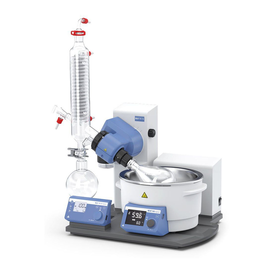
    EG-KONFORMITÄTSERKLÄRUNG Wir erklären in alleiniger Verantwortung, dass dieses Produkt den Bestimmungen der Richtlinien 2006/95/EG, 98/37/EG und 2004/108/EG entspricht und mit den folgenden Normen und normativen Dokumenten übereinstimmt: DIN EN IEC 61010-1, -2-051; DIN EN ISO 12100-1, -2; EN 60204-1 und DIN EN IEC 61326-1. CE-DECLARATION OF CONFORMITY We declare under our sole responsibility that this product corresponds to the regulations 2006/95/EC, 98/37/EC and 2004/108/EC and conforms with the standards or standardized documents DIN EN IEC 61010-1, -2-051;...
  • Page 4 L’appareil complet, incl. les accessoires HB 10.1 bouclier anti-projections et HB 10.2 capot de protection Комплектная установка с дополнительным защитным экраном HB 10.1 и защитным колпаком HB 10.2 Pos. Bezeichung Antrieb RV 10 basic / digital HB 10.2 Schutzhaube (nicht im Lieferumfang enthalten) HB 10.1 Schutzschild (nicht im Lieferumfang enthalten) Heizbad HB 10 Halter Woulff’sche Flasche...
  • Page 5 Funktionstasten / Function keys / Touches de fonction / Teclas de función / Функциональные кнопки RV 10 basic ® RV 10 digital ® Fig. 2 Pos. Bezeichung Item Designation Pos. Designation Taste "Power" "Power" key Touche "Power" Taste Liftposition " "...
  • Page 6: Table Des Matières

    Ursprungssprache Inhaltsverzeichnis Seite EG-Konformitätserklärung Zeichenerklärung Gewährleistung Sicherheitshinweise Bestimmungsgemäßer Gebrauch Auspacken Wissenswertes Aufstellung Antrieb RV 10 basic/ digital Heizbad Glassatz Verschlauchung Schnittstellen und Ausgänge Inbetriebnahme Wartung und Reinigung Zubehör Fehlercodes Technische Daten Lösemitteltabelle (Auswahl) Ze iche nerklärung Allgemeiner Gefahrenhinweis Verbrennungsgefahr! Gewährleistung Entsprechend den IKA ®...
  • Page 7: Sicherheitshinweise

    Sicherheitshinweise Zu Ihrem Schutz • Lesen Sie die Betriebsanleitung vor Inbetriebnah- • Passen Sie die Menge und Art des Destillationsgutes an die Größe der me vollständig und beachten Sie die Sicherheits- Destillationsapparatur an. Der Kühler muss ausreichend wirksam sein. hinweise. Überwachen sie den Kühlmitteldurchfluss am Ausgang des Kühlers.
  • Page 8: Bestimmungsgemäßer Gebrauch

    • Vermeiden Sie Stöße und Schläge auf das Gerät oder Zubehör. • Das Gerät darf nur von einer Fachkraft geöffnet werden. Bestimmungsgemäßer Gebrauch • Verwendung Das Gerät ist in Verbindung mit dem von IKA ® empfohlenen Zubehör • Verwendungsgebiet geeignet für:...
  • Page 9: Auspacken

    • Auspacken - Packen Sie das Gerät vorsichtig aus - Nehmen Sie bei Beschädigungen sofort den Tatbestand auf (Post, Bahn oder Spedition) • Lieferumfang siehe Tabelle RV 10 basic V asic asic asic RV 10 digital V RV 10 digital VC...
  • Page 10: Aufstellung

    Aufstellung Antrieb RV 10 basic/digtal  Lösen Sie die Klemmvorrichtung zur Winkeleinstellung des Rotations- antriebes auf der rechten Liftseite durch Drehen der Griffschraube (E) Achtung! Transportsicherung lösen (Fig. 4a)! gegen den Uhrzeigersinn (durch leichtes Drücken und gleichzeitiges Drehen lässt sich die Griffschraube (E) weiter aus- bzw. einfahren).
  • Page 11 Erstinbetriebnahme - Montage der Dichtung RV 10.8001  Führen Sie das Dampfdurchführungsrohr bis auf Anschlag ein.  Verriegeln Sie anschließend diese Arretierung durch Drehen um 60°  Dampfdurchführungsrohr einsetzen (1). im Uhrzeigersinn (Fig. 10).  Dichtung RV 10.8001 einsetzen (2). ...
  • Page 12 Montage Glassatz Glassatz Glassatz RV 10.2 diagonal RV 10.1 vertikal RV 10.20 diagonal, beschichtet RV 10.10 vertikal, beschichtet Rotationsantrieb Rotationsantrieb Pos. Bezeichnung Menge Menge Glassatz diagonal Glassatz vertikal Auffangkolben Klemme NS 29 Dampfdurchführungsrohr Absperrhahn Rohr Kühler 1 Diagonalkühler 1 Vertikalkühler Anschluss 1 Einleithülse 1 Vakuumanschluss...
  • Page 13: Verschlauchung

    Demontage Kühler Beschreibung Sonderkühler  Verwenden Sie den mitgelieferten Ringschlüssel zum Lösen festsitzen- • RV 10.3 Vertikal-Intensivkühler mit Verteilerstück der Überwurfmuttern. Mit Doppelmantel ausgeführter Vertikal-Intensivkühler, ermöglicht be-  Lösen Sie die Überwurfmutter durch Drehen gegen den Uhrzeigersinn. sonders effiziente Kondensationen. ...
  • Page 14: Schnittstellen Und Ausgänge

    Displayseite des Heizbades bzw. an der rechten Dis- playseite der Antriebseinheit. Stellen Sie keine Gegenstände zwischen von z.B. Drehzahlrampen erlaubt. die zwei Bedieneinheiten, da ansonsten die Datenübertragung gestört Nachfolgend sehen Sie eine Übersicht der von den IKA ® Control- Geräten ist (Fig. 15)! verstandenen (NAMUR)-Befehlen.
  • Page 15: Inbetriebnahme

    Inbetriebnahme  Auf dem Display erscheint der zuvorgespeicherte Wert. Das Gerät ist nach Einstecken des Netzste- ckers betriebsbereit.  Deaktivieren Sie den Timer durch Einstellen des Sollwertes “0”. Netzschalter (Fig. 17)  Schalten Sie das Gerät auf der rechten Geräteseite ein. •...
  • Page 16: Wartung Und Reinigung

    (siehe Kapitel Sicherheitshinweise - Sicherheitsanhebung)! Funktioniert Ziehen Sie zum Reinigen den Netzstecker. die Sicherheitsanhebung nicht mehr, kontaktieren Sie sich bitte die IKA ® Serviceabteilung. Für die Reinigung des Gerätes ist ausschließlich Wasser mit einem tensid- haltigen Waschmittelzusatz oder bei stärkerer Verschmutzung Isopropyl-...
  • Page 17: Zubehör

    Verwenden Sie hierzu das im Lieferumfang fährdenden Stoffen sein. - Fabrikationsnummer des Gerätes, siehe Typenschild, beigefügte Formular “Unbedenklichkeitsbescheinigung“ oder - Positionsnummer und Bezeichnung des Ersatzteiles, siehe Ersatzteilbild den Download-Ausdruck des Formulares auf der IKA ® Website und -liste unter www.ika.com. www.ika.com.
  • Page 18 RV 10.2001 NS 29/42 Verdampferkolben 50 ml RV 10.2002 NS 29/42 Verdampferkolben 100 ml RV 10.2003 NS 29/42 Verdampferkolben 250 ml RV 10.2004 NS 29/42 Verdampferkolben 500 ml RV 10.87 NS 29/42 Verdampferkolben 1000 ml RV 10.2005 NS 29/42 Verdampferkolben 2000 ml RV 10.2006 NS 29/42 Verdampferkolben 3000 ml RV 10.2007...
  • Page 19: Fehlercodes

    Prüfen/ reinigen Sie die Schnittstelle Heizbad Lässt sich der Fehler durch die beschriebenen Maßnahmen nicht beseitigen oder bei einem anderen Fehler: - wenden Sie sich bitte an die IKA ® Serviceabteilung, - senden Sie das Gerät mit einer kurzen Fehlerbeschreibung ein.
  • Page 20: Technische Daten

    Technische Daten nur RV 10 basic nur RV 10 digital Betriebsspannungsbereich 100 - 230 + 10% Nennspannung 100 - 230 Frequenz 50 / 60 Anschlussleistung ohne Heizbad Anschlussleistung im Stand by-Betrieb Drehzahl 20-280 Drehzahlanzeige digital Display Abmessung Sichtbereich (B x H)
  • Page 21: Explication Of Warning Symbols

    Page CE-Declaration of conformity Explication of warning symbols Warranty Safety instructions Correct use Unpacking Useful information Setting up Drive RV 10 basic/ digital Heating bath Glassware Hose system Interfaces and outputs Commissioning Maintenance and cleaning Accessories Error codes Technical data...
  • Page 22: Safety Instructions

    Safety instructions For your protection • Read the operating instructions in full before • Use the HB 10.2 cover or the HB 10.1 spray guard. starting up and follow the safety instructions. • Only use the device under an all side-closed exhaust, or a compa rable •...
  • Page 23: Correct Use

    "Power" switch on the front panel. Maximum solvent load = 3100 g – 1980 g = 1320 g Due to the design, the safety lift cannot be guaranteed for higher loads! If the safety lift is not working, please contact the IKA Service depart- ®...
  • Page 24: Unpacking

    - Please unpack the device carefully - In the case of any damage a fact report must be sent immediately (post, rail or forwarder) • Delivery scope see table RV 10 basic V asic asic asic RV 10 digital V...
  • Page 25: Setting Up

    Setting up Drive RV 10 basic/digtal  Remove the clamping device for the angle setting of the rotation drive on the right side of the lift by rotating the knurled screw counter clock- Caution! Loosen transportation lock (Fig. 4a)! wise (by lightly pressing and turning at the same time, the knurled screw comes out farther).
  • Page 26 First use - Fitting the seal RV 10.8001  Feed the steam pipe in until it stops.  Then lock the locking device by turning it clockwise by 60° (Fig. 10).  Insert vapour tube (1).  Insert seal RV 10.8001 (2). ...
  • Page 27 Mounting the glassware Glassware Glassware RV 10.2 diagonal RV 10.1 vertical RV 10.20 diagonal, coated RV 10.10 vertical, coated Rotary head Rotary head Item Designation Quantity Quantity diagonal glassware vertical Glassware Receiving fl ask Clamp NS 29 (stainless steel) Steam pipe Stopcock Pipe tube Condenser...
  • Page 28: Hose System

    Removing the condenser Description of special condensers  Use the ring spanner provided to loosen union nuts that are tightly • RV 10.3 Vertical-intensive condenser with manifold fitted. This vertical-intensive condenser features a double jacket design for  Loosen the union nut by turning anticlockwise. particularly efficient condensation.
  • Page 29: Interfaces And Outputs

    NAMUR working party (NAMUR recommendations for the design of electrical plug connections for analogue and digital signal transmission on individual items of laboratory control equipment, rev. 1.1. The NAMUR commands and the additional specific IKA ® co mmands serve only as low level commands for communication between the rotary eva- porator and the PC.
  • Page 30: Commissioning

    Commissioning  The previously saved value appears on the display. The unit is ready for service when the mains plug has been plugged in.  Deactivate the timer by setting the target value to “0”. On/Off switch (Fig. 17)  Switch on the device on the right side of the device. •...
  • Page 31: Maintenance And Cleaning

    Prior to filling the evaporator piston, a vacuum controller is used to regu- late the glass apparatus to the target pressure. Note: If non-original accessories are used that are not supplied by IKA ® then it is possible that the 50 mm travel range provided by the heating ...
  • Page 32: Accessories

    - Machine type rials which may constitute a health hazard. For this use the "certifi cate - Manufacturing number, see type plate of compliance" included or download the form from the IKA website ® - Item and designation of the spare part, www.ika.com.
  • Page 33 RV 10.2001 NS 29/42 Evaporator piston 50 ml RV 10.2002 NS 29/42 Evaporator piston 100 ml RV 10.2003 NS 29/42 Evaporator piston 250 ml RV 10.2004 NS 29/42 Evaporator piston 500 ml RV 10.87 NS 29/42 Evaporator piston 1000 ml RV 10.2005 NS 29/42 Evaporator piston 2000 ml RV 10.2006...
  • Page 34: Error Codes

    Check / clean the interface heating bath If the actions described fail to resolve the fault or another error code is displayed then take one of the following steps: - contact the IKA service department, ® - send the device for repair, including a short description of the fault.
  • Page 35: Technical Data

    Technical Data only RV 10 basic only RV 10 digital Operating voltage range 100 - 230 + 10% Rated voltage 100 - 230 Frequence 50 / 60 Power input without heating bath Power input in operation “Stand by” Speed 20-280...
  • Page 36: Explication Des Symboles

    Explication des symboles Remarque générale sur un danger Risque de brûlure! Garantie En conformité avec les conditions de vente et de livraison de IKA ® , la La garantie ne s’étend pas aux pièces d’usure et n’est pas valable en cas garantie sur cet appareil est de 24 mois.
  • Page 37: Conseils De Sécurité

    Conseils de sécurité Pour votre protection • Lisez intégralement la notice d'utilisation avant • Lors des travaux sous pression normale, la structure en verre doit tou- la mise en service et respectez les consignes de sé- jours être ventilée (par ex. sortie ouverte du refroidisseur) pour éviter curité.
  • Page 38: Utilisation Selon Des Directives

    Un dispositif de levage de sécurité avec des charges plus lourdes ne peut Si le dispositif de levage de sécurité ne fonctionnent pas, veuillez contac- être garanti pour des raisons de conception ! ter le service après-vente IKA ® En cas d'utilisation d'autres types de condenseurs, par ex. à neige carbo- Concernant l'évaporateur (ballon d'évaporation plus contenu), le poids...
  • Page 39: Déballage

    - Déballez l'appareil avec précaution - En cas de dommage, établiez immédiatement un constat correspon- dant (poste, chemins de fer ou transporteur) • Volume de livraison voir tableau RV 10 basic V asic asic asic RV 10 digital V RV 10 digital VC...
  • Page 40: Installation

    Installation Entraînement RV 10 basic/ digital  Desserrez le dispositif de serrage pour régler l'angle de l'entraînement de ro- tation du côté droit du dispositif de levage en tournant la vis à poignée (E) Attention ! Desserrez la sécurité de transport (fig. 4a) ! dans le sens inverse des aiguilles d'une montre (en appuyant légèrement et en...
  • Page 41 Avant la mise en service - Montage du joint RV 10.8001  Insérez la traversée de vapeur jusqu'en butée.  VVerrouillez ensuite ce dispositif d'arrêt en tournant à 60° dans le sens  Montez le conduit de vapour (1). des aiguilles d'une montre (Fig. 10). ...
  • Page 42 Montage de la verrerie Verrerie Verrerie RV 10.2 diagonale RV 10.1 verticale RV 10.20 diagonale, avec revêtement RV 10.10 verticale, avec revêtement Entraînement de rotation Entraînement de rotation Pos. Désignation Quantité Quantité Verrerie diagonale Verrerie verticale Ballon récepteur Pince NS 29 Traversée de vapeur Robinet d'arrêt Tube...
  • Page 43: Gainage

    Démontage du condenseur Description des condenseurs spéciaux  Utilisez la clé à œil fournie pour desserrer les écrous d'accouplement • RV 10.3 Condenseur intensif vertical avec distributeur coincés. Condenseur intensif vertical à double paroi permettant des condensa-  Desserrez les écrous d'accouplement en tournant dans le sens inverse tions particulièrement efficaces.
  • Page 44: Interfaces Et Sorties

    NAMUR (recommandations NAMUR pour l’exécution des connecteurs électriques pour la transmission analogique et numérique des signaux aux appareils de laboratoire MSR, Rév. 1.1. Les instructions NAMUR et les instructions supplémentaires IKA ® spécifiques servent uniquement d’instructions Low level pour la communication entre Fig.
  • Page 45: Mise En Service

    Mise en service  La valeur enregistrée s'affiche. L’appareil est prêt à fonctionner après avoir connecté la prise de secteur.  Désactivez le minuteur en réglant la valeur théorique sur “0”. Interrupteur (fig. 17)  Allumez l'appareil du côté droit •...
  • Page 46: Entretien Et Nettoyage

    3 kg. Fig. 18 Fig. 20 Installation du bain chauffant Lisez également le mode d'emploi du bain chauffant IKA HB 10! ®  Abaissez le dispositif de levage dans sa position inférieure et vérifiez la Fig.
  • Page 47: Accessoires

    Web d'IKA  : www.ika.com. ® www.ika.com, le tableau des pièces de rechange et catalogue des Renvoyez l’appareil dans son emballage d’origine. Les emballages de pièces de rechange. stockage ne sont pas suffi sants pour le renvoi. Utilisez un emballage de transport supplémentaire adapté.
  • Page 48 RV 10.94 NS 24/32 Ballon d'évaporation 1000 ml RV 10.95 NS 24/32 Ballon d'évaporation 2000 ml RV 10.96 NS 24/32 Ballon d'évaporation 3000 ml RV 10.97 NS 24/40 Ballon d'évaporation 1000 ml RV 10.2001 NS 29/42 Ballon d'évaporation 50 ml RV 10.2002 NS 29/42 Ballon d'évaporation 100 ml RV 10.2003...
  • Page 49: Messages D'erreurs

    Contrôlez/ nettoyez le port bain chauffant Si le défaut persiste après les mesures prescrites ou si un autre code d'erreur s'affi che ® - Adressez-vous au département de service d' IKA - Envoyez l'appareil avec un bref descriptif de l'erreur.
  • Page 50: Caractéristiques Techniques

    Caractéristiques techniques seulement RV 10 basic seulement RV 10 digital Plage de tension de service 100 - 230 + 10% Tension nominale 100 - 230 Fréquence 50 / 60 Puissance absorbée sans bain chauffant Puissance absorbée en mode d’opération “stand by”...
  • Page 51: Declaración Del Marcado

    Declaracion de conformidad de CE Declaración del marcado Garantía Indicaciones de seguridad Uso conforme al previsto Desempacado Informaciones importantes Instalación Accionamiento RV 10 basic/ digital Baño calefactor Equipo de vidrio Manguera Interfaces y salidas Puesta en servicio Mantenimiento y limpieza Accesorios Códigos de error...
  • Page 52: Indicaciones De Seguridad

    Indicaciones de seguridad Para su protección • Lea todas las instrucciones de uso antes de la • Adapte la cantidad y el tiempo de material a destilar al tamaño del equipo puesta en marcha y siga siempre las instrucciones de destilación. El refrigerador debe tener un potencial de acción suficiente. de seguridad.
  • Page 53: Uso Conforme Al Previsto

    Si el mecanismo de elevación de seguridad no funciona, póngase en contacto con el departamento de servicio técnico de IKA ® Si se utilizan otros tipos de refrigeradores, como pueden ser los de hielo seco o los intensivos, así...
  • Page 54: Desempacado

    - Desembale el aparato con cuidado - Si observa desperfectos, rellene enseguida el registro correspon- diente (correo, ferrocarril o empresa de transportes) • Volumen de suministro consulte la tabla RV 10 basic V asic asic asic RV 10 digital V...
  • Page 55: Instalación

    Instalación Accionamiento RV 10 basic/digtal  Afloje el dispositivo de apriete para ajustar el ángulo del accionamiento de rotación que se encuentra en el lado derecho del elevador girando el tornillo Atención: Quite el dispositivo de protección para el transporte (fig. 4a)! del asa (E) en el sentido contrario a las agujas del reloj (si presiona ligeramente el tornillo del asa (E) al tiempo que lo gira, éste puede seguir extrayéndose).
  • Page 56 Ante puesta en servizio - Montaje del junta RV 10.8001  Introduzca el tubo de paso de vapor hasta el tope.  Bloque a continuación este inmovilizador girándolo 60° en el sentido  Monte el tubo de paso del vapor(1). de las agujas del reloj (fig.
  • Page 57 Montaje del equipo de vidrio Equipo de vidrio Equipo de vidrio RV 10.2 diagonal RV 10.1 vertical RV 10.20 diagonal, recubierto RV 10.10 vertical, recubierto Accionamiento de rotación Accionamiento de rotación Pos. Designación Cantidad Cantidad Equipo de vidrio diagonal Equipo de vidrio vertical Matraz de recepción Pinza de fi...
  • Page 58 Desmontaje del radiador Descripción del refrigerador especial  Utilice la llave poligonal incluida para aflojar la tuerca de racor fija • RV 10.3 Refrigerador vertical intensivo con pieza de distribución  Afloje la tuerca de racor girándola hacia la izquierda. Refrigerador vertical intensivo realizado con doble revestimiento, lo que ...
  • Page 59: Interfaces Y Salidas

    PC. Estos comandos se pueden transmitir con un programa de HB 10 terminal o comunicación apropiado directamente al aparato. Labworldsoft es un cómodo paquete de software de IKA que se utiliza El baño calefactor transfiere datos a través de interfaces de infrarrojos ®...
  • Page 60: Puesta En Servicio

    Puesta en sevicio  En la pantalla aparece el valor almacenado antes. El aparato está listo para el funcionamien- to después de insertar el enchufe a la red.  Desactive el temporizador ajustando el valor nominal “0”. Conmutador de alimentación (fig. 17) ...
  • Page 61: Mantenimiento Y Limpieza

    Antes de llenar el matraz de evaporación los aparatos de vidrio se regulan calefactor al introducir el matraz de evaporación en el baño calefactor. a la presión nominal mediante el mecanismo de control de vacío. Nota: Si utiliza otros accesorios distintos de los originales de IKA ® , pue- ...
  • Page 62: Accesorios

    - el modelo del aparato do de no objeción" que se incluye en el volumen de suministro o descargue - la designación del repuesto (en www.ika.com encontrará las imáge- el impreso del formulario en la página web de IKA www.ika.com.
  • Page 63 RV 10.85 NS 29/32 Matraz de evaporación 2000 ml RV 10.86 NS 29/32 Matraz de evaporación 3000 ml RV 10.90 NS 24/32 Matraz de evaporación 50 ml RV 10.91 NS 24/32 Matraz de evaporación 100 ml RV 10.92 NS 24/32 Matraz de evaporación 250 ml RV 10.93 NS 24/32 Matraz de evaporación 500 ml RV 10.94...
  • Page 64: Códigos De Error

    Interfaz tapada o sucia Compruebe o limpie la interfaz. baño calefactor Si el error no se puede eliminar mediante las medidas descritas: - diríjase a la Sección de servicio técnico IKA ® - envíe el aparato junto con una breve descripción del fallo.
  • Page 65: Datos Técnicos

    Datos técnicos solo RV 10 basic solo RV 10 digital Intervalo de tensión de servicio 100 - 230 + 10% Tensión nominal 100 - 230 Frecuencia 50 / 60 Rendimiento de la conexión sin baño calefactor Rendimiento de la conexión en funcionamiento “stand by”...
  • Page 66: Условные Обозначения

    Техобслуживание и чистка Принадлежности Коды ошибок Технические данные Таблица растворителей (выбор) Условные обозначения Общее указание на опасность Опасность получения ожогов! Гарантия В соответствии с условиями продажи и поставки IKA ® срок гарантии составляет Гарантия не распространяется на изнашивающиеся детали, случаи...
  • Page 67: Указания По Технике Безопасности

    Указания по технике безопасности Для вашей защиты • Перед вводом в эксплуатацию полностью прочитайте • Количество и тип дистиллята должны соответствовать размеру дистилляционного инструкцию по эксплуатации и соблюдайте указания по оборудования. Охладитель должен обладать достаточной эффективностью. технике безопасности. Контролируйте расход охлаждающего средства на выходе охладителя. •...
  • Page 68 Максимальный вес растворителя = 3100 г – 1980 г = 1320 г Если устройство аварийного подъема не функционирует, обратитесь в сервисную При большем весе аварийный подъем может не обеспечиваться, что службу компании IKA ® обусловлено конструкцией! Со стороны испарителя (испарительная колба плюс содержимое) максимально...
  • Page 69: Важные Замечания

    - Осторожно распакуйте прибор. - При наличии повреждений немедленно выясните их причину (почта, железная дорога или транспортное агентство). • Комплект поставки См. таблицу RV 10 basic V RV 10 basic VC RV 10 basic D RV 10 basic DC RV 10 digital V...
  • Page 70 Размещение Привод RV 10 basic/digital  Открутите зажимное приспособление для регулировки угла ротационного привода с правой стороны подъемника, повернув винт с грибком (E) против Внимание! Открутите транспортировочное крепление (рис. 4a)! часовой стрелки (посредством легкого нажатия и одновременного поворота винт с грибком (E) можно выдвигать или задвигать).
  • Page 71 Первый ввод в эксплуатацию: монтаж уплотнения RV 10.8001  Вставьте паропроводную трубку до упора.  Затем заблокируйте этот фиксатор, повернув его на 60° по часовой стрелке  Вставьте паропроводную трубку (1). (рис. 10).  Вставьте уплотнение RV 10.8001 (2).  Установите охладитель (3a). ...
  • Page 72 Монтаж стеклянной посуды RV 10.2 RV 10.1 RV 10.20 RV 10.10 Поз. Наименование Количество Количество Диагональная стеклянная посуда Вертикальная стеклянная посуда Приемная колба Зажим NS 29 Паропроводная трубка Запорный кран Трубка Охладитель 1 диагональный охладитель 1 вертикальный охладитель Подсоединение 1 входная гильза 1 акуумное...
  • Page 73 Демонтаж охладителя Описание специального охладителя  Используйте входящий в комплект поставки кольцевой гаечный ключ для • Вертикальный высокоэффективный охладитель RV 10.3 с распределителем откручивания плотно пригнанных накидных гаек. Вертикальный высокоэффективный охладитель с двойной рубашкой  Открутите накидную гайку, повернув ее против часовой стрелки. обеспечивает...
  • Page 74: Интерфейсы И Выходы

    соответствующего терминала и программы связи эти команды могут передаваться HB 10 Нагревательная баня передает данные через ИК-интерфейсы. Они расположены напрямую на прибор. Labworldsoft — это удобный пакет программ IKA ® работающих в среде MS Windows и предназначенных для управления прибором...
  • Page 75 Ввод в эксплуатацию  На дисплее появляется ранее сохраненное значение Прибор готов к эксплуатации после вставки сетевого штекера в розетку.  Для деактивации таймера установите заданное значение «0» Сетевой выключатель (рис. 17)  Включите прибор с правой стороны. • Кнопка «Инт» (6) ...
  • Page 76 при использовании неоригинальных принадлежностей, устанавливается на заданное давление с помощью регулятора вакуума. поставляемых не компанией IKA ® , смещения нагревательной бани на 50 мм будет недостаточно, в частности при использовании испарительной колбы  Заполните испарительную колбу через подающий трубопровод. объемом 3 л и пеногасителя.
  • Page 77 «Свидетельство о безопасности» или распечатку бланка, скаченную с веб-сайта - номер позиции и обозначение запчасти, см. рисунки и список запчастей на ® www.ika.com. сайте www.ika.com. Отправляйте прибор в оригинальной упаковке. Складской упаковки для обратной отправки недостаточно. Используйте дополнительно подходящую транспортировочную упаковку.
  • Page 78 RV 10.2001 Испарительная колба NS 29/42 50 мл RV 10.2002 Испарительная колба NS 29/42 100 мл RV 10.2003 Испарительная колба NS 29/42 250 мл RV 10.2004 Испарительная колба NS 29/42 500 мл RV 10.87 Испарительная колба NS 29/42 1000 мл RV 10.2005 Испарительная...
  • Page 79: Коды Ошибок

    Мотор заблокирован Нет связи с нагревательной баней Интерфейс закрыт или загрязнен Проверьте/очистите интерфейс Если неисправность не удается устранить посредством описанных мер, или имеет место другая неполадка: - обратитесь в сервисную службу IKA ® - отправьте прибор с кратким описанием неполадки.
  • Page 80 Технические данные Только RV 10 basic Только RV 10 digital Диапазон рабочего напряжения В~ 100 - 230 + 10% Номинальное напряжение В~ 100 - 230 Частота Гц 50 / 60 Присоединяемая мощность без нагревательной бани Вт Присоединяемая мощность в режиме ожидани...
  • Page 82 Notes...
  • Page 84 - Werke ® GmbH & Co.KG Janke & Kunkel-Str. 10 D-79219 Staufen Tel. +49 7633 831-0 Fax +49 7633 831-98 sales@ika.de www.ika.com 00/0000/0...

Ce manuel est également adapté pour:

Rv 10 digital

Table des Matières