CAME ZLX24MA Mode D'emploi
Masquer les pouces
Voir aussi pour ZLX24MA:
- Manuel d'installation (41 pages) ,
- Manuel d'installation (48 pages) ,
- Manuel d'installation (48 pages)
Table des Matières
Publicité
Les langues disponibles
Les langues disponibles
Liens rapides
Publicité
Table des Matières

Manuels Connexes pour CAME ZLX24MA


Sommaire des Matières pour CAME ZLX24MA
- Page 1 FA01578M04 ZLX24MA ZLX24MR Italiano English Français Pусский...
-
Page 2: Avvertenze Generali Per L'installatore
fi nale in accordo alla Direttiva Macchine 2006/42/CE ed agli standard tecnici armonizzati di riferimento sono identifi cati nel catalogo generale dei prodotti CAME oppure nel sito internet www.came.com. • Verifi care che il range di temperature indicato sia adatto al luogo di installazione. - Page 3 • Prima di procedere con l'installazione, verifi care che la parte guidata sia in buone condizioni meccaniche, e che si apra e si chiuda correttamente. • Il prodotto non può essere utilizzato per automatizzare una parte guidata comprensiva di porta pedonale, a meno che l'azionamento non sia attivabile solo con la porta pedonale in posizione di sicurezza.
-
Page 4: Dismissione E Smaltimento
UNI EN ISO 14001 a garanzia del rispetto e della tutela dell’ambiente. Vi chiediamo di continuare l’opera di tutela dell’ambiente, che CAME considera uno dei fondamenti di sviluppo delle proprie strategie operative e di mercato, semplicemente osservando brevi indicazioni in materia di smaltimento: SMALTIMENTO DELL’IMBALLO... - Page 5 Descrizione 801QA-0050 ZLX24MA - Quadro comando multifunzioni, con alimentazione a 230 V AC, per cancelli a due ante battenti a 24 V, con display di programmazione e segnalazione, autodiagnosi dei dispositivi di sicurezza, Adaptive Speed & Torque Technology, BUS CXN, 2 ingressi di sicurezza e memorizzazione fi...
-
Page 6: Descrizione Delle Parti
Morsettiera per il collegamento del motoriduttore sicurezza con encoder o con interruttore di rallentamento ed Connettore per scheda Memory Roll elettroserratura Connettore per CAME KEY Fusibile per gli accessori Display Fusibile per la scheda elettronica Tasti per la programmazione Morsettiera per il collegamento dei dispositivi di... - Page 7 Accessori opzionali Scheda carica batterie RLB (002RLB) Modulo RGSM001 (806SA-0010) Modulo SMA (009SMA)
- Page 8 Dimensioni...
- Page 9 Per i collegamenti di prodotti non contemplati in questo manuale fa fede la documentazione allegata ai prodotti stessi. Per il collegamento dell'Encoder, utilizzare un cavo tipo FRORPU 3 x 0,5mm2 o un cavo fornito da CAME su richiesta (codice articolo 801XA-0020).
- Page 10 INSTALLAZIONE Preparazione del quadro comando...
- Page 11 Fissaggio del quadro comando Barra DIN Standard...
-
Page 12: Collegamenti Elettrici
COLLEGAMENTI ELETTRICI Predisposizione dei cavi elettrici Eseguire i collegamenti elettrici secondo le disposizioni vigenti. Utilizzare dei pressacavi per collegare i dispositivi al quadro comando. Uno di questi deve essere destinato esclusivamente per il cavo di alimentazione. - Page 13 Alimentazione Collegamento alla rete elettrica (230/120 V AC - 50/60 Hz) F - Fusibile di linea L - Cavo di fase N - Cavo neutro Cavo di terra La fascetta utilizzata per fi ssare i cavi non è fornita. Uscita alimentazione per accessori L'uscita eroga normalmente 26 V AC.
- Page 14 Alimentazione (V) Potenza (W) BUS CXN 15 DC Non collegare niente di diverso dagli accessori BUS Came. Motoriduttori M1 =Motoriduttore ritardato in apertura M2 =Motoriduttore ritardato in chiusura In caso di un impianto con un solo motoriduttore, i collegamenti elettrici vanno eseguiti sul motoriduttore (M2).
- Page 15 M1 N1 ENC1 EB1+VB M2 N2 ENC2 EB2+VB ATS / AXO / FTX / FAST-70 / AMICO / AXI M2 N2 ENC2 EB2+VB M1 N1 ENC1 EB1+VB STYLO-RME M1 N1 ENC1 EB1+VB M2 N2 ENC2 EB2+VB STYLO-ME...
- Page 16 Motoriduttori con interruttori di rallentamento FC1 FA1 F FC2 FA2 F M1 N1 ENC1 EB1+VB M2 N2 ENC2 EB2+VB A3024N / A5024N E1 - E2 - M1 N1 ENC1 EB1+VB M2 N2 ENC2 EB2+VB FC1 FA1 F FC2 FA2 F FROG-A24 E1 - E2 -...
- Page 17 Motoriduttori senza encoder M2 N2 ENC2 EB2+VB M1 N1 ENC1 EB1+VB...
- Page 18 Dispositivi con sistema BUS CXN Il sistema CXN di CAME è un BUS di comunicazione a 2 fi li non polarizzato che permette di collegare tutti i dispositivi CAME compatibili. La connessione al bus può essere a Catena, a Stella oppure Mista.
-
Page 19: Dispositivi Di Comando
Dispositivi di comando Pulsante di STOP (contatto NC) Arresta il cancello ed esclude l’eventuale chiusura automatica. Usare un dispositivo di comando per riprendere il movimento. Quando il contatto viene utilizzato deve essere attivato in fase di programmazione. Dispositivo di comando (contatto NO) Funzione SOLO APRE Con funzione [AZIONE MANTENUTA] attiva, è... -
Page 20: Dispositivi Di Segnalazione
Dispositivi di segnalazione Lampeggiatore Lampeggia durante le fasi di apertura e chiusura dell'automazione. Lampada supplementare Aumenta l'illuminazione nella zona di manovra. Vedi funzione [Lampada supplementare]. Spia stato automazione Segnala lo stato dell'automazione. Vedi funzione [Spia varco aperto]. 10 11 E E3 5... -
Page 21: Dispositivi Di Sicurezza
Dispositivi di sicurezza In fase di programmazione, confi gurare il tipo di azione che deve essere svolta dal dispositivo collegato all'ingresso. Collegare i dispositivi di sicurezza agli ingressi CX e/o CY. Se vengono utilizzati, i contatti CX CY devono essere confi gurati in fase di programmazione. In caso di impianto con più... - Page 22 Fotocellula DXR - DLX Fotocellula DXR - DLX Collegamento standard Collegamento con test di sicurezza Vedi funzione [Test sicurezze]. 10 11 E E3 5 10 TS 2 CX CY 10 11 E E3 5 10 TS 2 CX CY 10 11 OUT 10 11 OUT 10 11 SY 10 11 SY...
- Page 23 PROGRAMMAZIONE Funzione dei tasti di programmazione Tasto ESC Il tasto ESC permette di eseguire le operazioni di seguito descritte. Uscire dal menu Annullare le modifi che Tornare alla schermata precedente Tasti < > I tasti < > permettono di eseguire le operazioni di seguito descritte. Navigare attraverso le voci del menu Incrementare o decrementare un valore Tasto ENTER...
-
Page 24: Messa In Funzione
Messa in funzione Terminati i collegamenti elettrici, procedere con la messa in funzione. L'operazione deve essere eff ettuata solo da personale esperto e qualifi cato. Controllare che l’area di manovra sia libera da qualsiasi ostacolo. Dare tensione e procedere con la programmazione. Iniziare la programmazione con le funzioni di seguito indicate. - Page 25 Rappresentazione grafica delle velocità, rallentamenti e accostamenti di un’anta Finecorsa in chiusura Velocità di apertura Finecorsa in apertura Velocità di chiusura Punto di rallentamento in apertura Velocità di rallentamento in apertura Punto di rallentamento in chiusura Velocità di rallentamento in chiusura Punto di accostamento in apertura Velocità...
-
Page 26: Menu Delle Funzioni
Senza utilizzo dello spazio di rallentamento (spazio di rallentamento = 0) Velocità di apertura o chiusura Velocità di accostamento (fi ssa) Sensibilità ostacoli in corsa Finecorsa in apertura o chiusura Punto di accostamento in apertura o chiusura Encoder virtuale Con motoriduttori senza encoder o con encoder disattivato, la gestione della corsa avviene tramite un ENCODER VIRTUALE. La taratura della corsa va SEMPRE eseguita, come nel caso di motore con encoder. - Page 27 Ingresso CX Associa una funzione all’ingresso CX. OFF (Default) C1 = Riapertura durante la chiusura (Fotocellule) C2 = Richiusura durante l'apertura (Fotocellule) C3 = Stop parziale Solo con [Ch. automatica] attivata. C4 = Attesa ostacolo (Fotocellule) C7 = Riapertura durante la chiusura (Bordi sensibili) C8 = Richiusura durante l'apertura (Bordi sensibili) C13 = Riapertura durante la chiusura con chiusura immediata dopo la rimozione dell'ostacolo, anche con cancello non in movimento...
- Page 28 Azione mantenuta Con la funzione attiva, il movimento dell’automazione (apertura o chiusura) si interrompe quando il dispositivo di comando viene rilasciato. L'attivazione della funzione esclude tutti gli altri dispositivi di comando. OFF (Default) Comando 2-7 Associa un comando al dispositivo collegato su 2-7. 0 = Passo-passo (Default) 1 = Sequenziale Spia varco aperto...
- Page 29 Elettroserratura Permette di associare lo sblocco dell'elettroserratura a un comando. OFF (Default) 1 = Da chiuso 2 = Da aperto 3 = Da aperto e chiuso 4 = Continua Lampada supplementare Permette di scegliere la modalità di funzionamento del dispositivo di illuminazione collegato all'uscita E3. OFF (Default) 1 = Lampada ciclo La lampada rimane accesa per tutta la manovra.
- Page 30 Tempo di ritardo in chiusura di M2 Regola il ritardo in apertura della seconda anta rispetto alla prima. Da 1 a 25 secondi (Default 2) Tempo cortesia Defi nisce quanti secondi la lampada supplementare (confi gurata come lampada di cortesia) rimane accesa dopo una manovra di apertura o chiusura.
- Page 31 AST control in rallentamento Regola, in percentuale, la sensibilità di rilevazione degli ostacoli durante la fase di rallentamento. Il parametro viene utilizzato solo se è attivo il punto di rallentamento in chiusura o in apertura. da 10% a 100% (Default 100%) 10% = minima spinta e elevata sensibilità...
- Page 32 Punto di accostamento in apertura di M2 Imposta la percentuale della corsa totale da utilizzare per l'accostamento in apertura di M2. Da 0.5% a 25.0% (Default 8.0%) Punto di accostamento in chiusura di M2 Imposta la percentuale della corsa totale da utilizzare per l'accostamento in chiusura di M2. Da 0.5% a 25.0% (Default 8.0%) Riduzione velocità...
- Page 33 Confi gura manutenzione Imposta il numero di manovre eseguibili dall'automazione prima che venga notifi cata la necessità di eff ettuare la manutenzione. L'avviso viene visualizzato a display con la scritta [SEr] e segnalato con lampeggi 3 + 3 ogni ora dal dispositivo collegato su 10-5.
- Page 34 RIO PH T1 Permette di associare una funzione tra quelle previste a un dispositivo di sicurezza wireless. La funzione appare solo se è presente la scheda di interfaccia RIO Conn. OFF (Default) P1 = Riapertura durante la chiusura. P2 = Richiusura durante l'apertura. P3 = Stop parziale.
- Page 35 Libera ostacolo In caso di ostacolo rilevato tramite l’AST control della scheda o da un ingresso di una costa, la funzione [Libera ostacolo] inverte l'anta solo per lo spazio necessario a liberare l'ostacolo poi si ferma. OFF = Inversione da ostacolo (Default) ON = Libera ostacolo Nuovo utente Permette di registrare un massimo di 250 utenti e di assegnare ad ognuno di essi una funzione.
- Page 36 Self-Learning Rolling Permette di memorizzare un nuovo trasmettitore rolling code attivando l'acquisizione da un trasmettitore rolling code già memorizzato. Le procedure di memorizzazione e di acquisizione sono spiegate nel manuale del trasmettitore. OFF (Default) Tipo motore Imposta il tipo di motoriduttore installato su M1 e M2. 0 = Generico 9 = AXO 1 = STYLO-ME...
- Page 37 Conteggi manovre Permette di visualizzare il numero di manovre eff ettuate dall'automazione, totale o parziale (dopo un'operazione di manutenzione). Il numero di manovre è il numero visualizzato moltiplicato per 100. Tot = Manovre totali Manovre eff ettuate dall'installazione dell'automazione. Par = Manovre parziali Manovre eff ettuate dopo l'ultima manutenzione.
- Page 38 Stato dispositivi BUS Indica lo stato di tutti i dispositivi che possono essere collegati al BUS e gestiti dal fi rmware in uso. Legenda Stato del dispositivo <x> b = Fotocellule BUS || = Indirizzo in confl itto d = Selettore BUS o = Funzionante L = Lampeggiatore BUS c = Funzionante con segnalazione di allarme...
- Page 39 Lampeggiatore BUS <Colore in apertura> Imposta il colore del lampeggiatore BUS durante l’apertura del cancello. La funzione appare solo se è presente un Lampeggiatore BUS collegato. Durante il conteggio che precede la chiusura automatica il colore del lampeggiatore è lo stesso di quello in apertura.
- Page 40 0 = Disattivato (Default) 1 = Bianco 2 = Giallo 3 = Arancio 4 = Rosso 5 = Viola 6 = Blu 7 = Azzurro 8 = Verde Con dispositivo CAME KEY, aggiornare sempre il fi rmware della scheda all'ultima versione disponibile.
-
Page 41: Salvataggio Dati
Esportare / importare dati È possibile salvare i dati relativi agli utenti e alla confi gurazione dell'impianto in una scheda MEMORY ROLL. I dati memorizzati possono essere riutilizzati in un'altra scheda elettronica dello stesso tipo per riportare le stesse confi gurazioni. Prima di inserire ed estrarre la scheda MEMORY ROLL, è... -
Page 42: Messaggi Di Errore
MESSAGGI DI ERRORE Errore di taratura del motore M1 Errore di taratura del motore M2 Errore segnale encoder non rilevato Errore di test servizi fallito Errore tempo di lavoro Ostacoli consecutivi rilevati durante la chiusura Ostacoli consecutivi rilevati durante l'apertura Errore massimo di ostacoli Tensione di alimentazione del motore mancante o non suffi ciente Errore su ingressi fi... -
Page 43: Operazioni Finali
OPERAZIONI FINALI Prima di chiudere il coperchio, verifi care che l’ingresso dei cavi sia sigillato per evitare l'entrata di insetti e la formazione di umidità. - Page 44 INCOLLARE QUI L'ETICHETTA DI PRODOTTO PRESENTE SULLA CONFEZIONE CAME S.p.A. Via Martiri della Libertà, 15 31030 Dosson di Casier Treviso - Italy Tel. (+39) 0422 4940 Fax (+39) 0422 4941...
- Page 45 Control panel for 24 V gearmotors FA01578-EN ZLX24MA ZLX24MR INSTALLATION MANUAL English...
- Page 46 fi nal installation to comply with the Machinery Directive (2006/42/EC) and with the reference harmonised technical standards are specifi ed in the general CAME product catalogue or on the website www.came.com. • Check that the temperature ranges given are suitable for the installation site.
- Page 47 • Before installation, check that the guided part is in good mechanical condition, and that it opens and closes correctly. • The product cannot be used to automate any guided part that includes a pedestrian gate, unless it can only be enabled when the pedestrian gate is secured.
-
Page 48: Dismantling And Disposal
UNI EN ISO 14001 standard to ensure that the environment is respected and safeguarded. Please continue safeguarding the environment. At CAME we consider it one of the fundamentals of our operating and market strategies. Simply follow these brief disposal guidelines: DISPOSING OF THE PACKAGING The packaging materials (cardboard, plastic, etc.) can be disposed of easily as solid urban waste, separated for recycling. - Page 49 Description 801QA-0050 ZLX24MA - Multifunction control panel, with 230 VAC power supply, for 24 V swing gates with two leaves, with programming display and signalling, safety device self-diagnostics, adaptive speed and torque technology, BUS CXN, 2 safety inputs and memory space for up to 250 users.
-
Page 50: Description Of Parts
Terminal boards for connecting micro limit switches and/ Terminal board for connecting the safety devices or encoders Memory Roll card connector Terminal board for connecting the gearmotor with Connector for CAME KEY encoder or with slowdown switch and electric lock Display Accessories fuse Programming buttons... - Page 51 Optional accessories RLB battery charger board (002RLB) RGSM001 module (806SA-0010) SMA module (009SMA)
- Page 52 Size...
- Page 53 For information on connecting products not covered in this manual, please see the documentation accompanying the products themselves. To connect the encoder, use a FRORPU 3 x 0.5 mm² cable or a cable supplied by CAME on request (item code 801XA-0020).
- Page 54 INSTALLATION Preparing the control panel...
- Page 55 Fastening the control panel DIN rail Standard...
-
Page 56: Electrical Connections
ELECTRICAL CONNECTIONS Preparing the electrical cables Connect all wires and cables in compliance with the law. Use cable glands to connect the devices to the control panel. One of these must be used exclusively for the power supply cable. -
Page 57: Power Supply
Power supply Connecting to the mains (230/120 V AC - 50/60 Hz) F - Line fuse L - Phase N - Neutral Earth The strap used to fi x the cables is not supplied. Power supply output for accessories The output normally delivers 26 V AC. The output delivers 24 V DC (10+, 11-) when the batteries start operating, if they are installed. - Page 58 Power supply (V) Power (W) BUS CXN 15 DC Do not connect anything other than CAME BUS accessories. Gearmotors M1 =Gearmotor delayed while opening M2 =Gearmotor delayed while closing Where there is only one gearmotor in the system, make the electrical connections on the gearmotor (M2).
- Page 59 M1 N1 ENC1 EB1+VB M2 N2 ENC2 EB2+VB ATS / AXO / FTX / FAST-70 / AMICO / AXI M2 N2 ENC2 EB2+VB M1 N1 ENC1 EB1+VB STYLO-RME M1 N1 ENC1 EB1+VB M2 N2 ENC2 EB2+VB STYLO-ME...
- Page 60 Gearmotors with slowdown switches FC1 FA1 F FC2 FA2 F M1 N1 ENC1 EB1+VB M2 N2 ENC2 EB2+VB A3024N / A5024N E1 - E2 - M1 N1 ENC1 EB1+VB M2 N2 ENC2 EB2+VB FC1 FA1 F FC2 FA2 F FROG-A24 E1 - E2 - M1 N1 ENC1 EB1+VB...
- Page 61 Gearmotors without encoder M2 N2 ENC2 EB2+VB M1 N1 ENC1 EB1+VB...
- Page 62 Devices with BUS CXN system The CXN CAME system is a two-wire non-polarised communication BUS which allows you to connect up all compatible CAME devices. Connection to the BUS can be in a chain, star or mixed formation. Once the system has been wired, and after having set the address on each device, the function of each accessory can be confi...
- Page 63 Command and control devices STOP button (NC contact) Stop the gate and exclude automatic closing. Use a control device to resume movement. When the contact is being used, it must be activated during programming. Control device (NO contact) OPEN ONLY function When the [HOLD-TO-RUN] function is active, the control device must be connected during OPENING.
- Page 64 Signalling devices Flashing beacon It fl ashes when the operator opens and closes. Additional light It increases the light in the manoeuvring area. See [Additional light] function. Operator status warning light It notifi es the user of the operator status. See function [Passage-open warning light].
-
Page 65: Safety Devices
Safety devices During programming, confi gure the type of action that must be performed by the device connected to the input. Connect the safety devices to the CX and/or CY inputs. If used, the contacts CX CY must be confi gured during programming. For systems with multiple pairs of photocells, please see the manual for the relevant accessory. - Page 66 DXR - DLX photocell DXR - DLX photocell Standard connection Connection with safety test See [Safety devices test] function. 10 11 E E3 5 10 TS 2 CX CY 10 11 E E3 5 10 TS 2 CX CY 10 11 OUT 10 11 OUT 10 11 SY 10 11 SY...
- Page 67 PROGRAMMING Programming button functions ESC button The ESC button is used to perform the operations described below. Exit the menu Delete the changes Go back to the previous screen < > buttons The <> buttons are used to perform the operations described below. Navigate the menu Increase or decrease values ENTER button...
-
Page 68: Getting Started
Getting started Once the electrical connections have been made, proceed with commissioning. Only skilled and qualifi ed staff may perform this operation. Make sure that there are no obstacles in the way. Power up the device and begin programming. Start programming with the functions indicated below. A1 Motor type F46 Number of motors A2 Motor test... - Page 69 Diagrams showing leaf speed, slowdown and approach points Closing limit-switch Opening speed Opening limit-switch Closing speed Opening slowdown point Opening slowdown speed Closing slowdown point Closing slowdown speed Opening approach point Approach speed (fi xed) Closing approach point Invert-motion zone in case of obstructions Stop-motion zone in case of obstructions Graph showing speed curves during movement, slowdown and approach.
-
Page 70: Functions Menu
Without using slowdown space (slowdown space = 0) Opening or closing speed Approach speed (fi xed) Obstruction travel sensitivity Opening or closing limit-switch Opening or closing approach point Virtual encoder For gearmotors without an encoder or with the encoder deactivated, travel is managed using a VIRTUAL ENCODER. ALWAYS calibrate the travel, as with motors with an encoder. - Page 71 CX input Associate a function with the CX input. OFF (Default) C1 = Reopen while closing (photocells) C2 = Reclose while opening (photocells) C3 = Partial stop Only with [Automatic close] activated. C4 = Obstacle standby (photocells) C7 = Reopen while closing (sensitive edges) C8 = Reclose while opening (sensitive edges) C13 = Reopen while closing, with immediate stop once the obstruction has been removed, even if the gate is not in motion...
- Page 72 Command 2-7 Associate a command to the connected device on 2-7. 0 = Step-by-step (default) 1 = Sequential Passage-open warning light It signals the gate status. The device is connected to output/terminal 5. 0 = Warning light on (default) - The warning light stays on when the gate is moving or open.
- Page 73 Additional light Choose the operating mode for the lighting device connected to output E3. OFF (Default) 1 = Cycle light The lamp stays on during the manoeuvre. The light remains off if an automatic closing time is not set. 2 = Courtesy lamp The light switches on when a manoeuvre starts and remains on once the manoeuvre has fi...
- Page 74 M1 leaf opening and closing speed Set the M1 travel speed (percentage of maximum speed). 40% to 100% (Default 70%) M2 leaf opening and closing speed Set the M2 travel speed (percentage of maximum speed). 40% to 100% (Default 70%) M1 leaf opening and closing slowdown speed Set the M1 slowdown speed during opening and closing (as a percentage of the maximum speed).
- Page 75 Opening slowdown point for M1 Set the percentage of the total travel to be used for M1 opening slowdown. OFF (Default) 1% to 50% M1 closing slowdown point Set the percentage of the total travel to be used for M1 closing slowdown. OFF (Default) 1% to 50% M1 opening approach point...
- Page 76 Number of motors Set the number of motors that control the gate. Value 1 indicates that the M2 motor is being used 2 (Default) Save data Save user data, timings and confi gurations to the memory device (memory roll). The function is displayed only when a memory roll card is inserted into the control board. ON (Run operation) Read data Upload user data, timings and confi...
- Page 77 RIO ED T1 Associate one of the available functions with a wireless safety device. The function only appears if the RIO CONN interface board is present. OFF (Default) P0 = It stops the gate and excludes automatic closing. Use a control device to resume movement.
- Page 78 Limit-switch function Set the operation of the inputs for slowdown/end-of-travel switches. The function only appears for motors confi gured for this purpose. After modifying the function of the slowdown/end-of-travel inputs, recalibrate [Function A3] If the inputs are used for slowdown, once calibration is complete, the board automatically sets the slowdown points.
- Page 79 Remove user Remove one of the registered users. No. 1 > 250 Use the arrows to choose the number associated with the user you want to remove. Alternatively, the control device associated with the user you want to remove can be activated.
- Page 80 Motor test Check the gate leaves open in the right direction. With the function active, the > key opens the gate leaf connected to M2, and the < key opens the gate leaf connected to M1. The movement continues while the key is pressed or until the end-of-travel limit switch is reached. When the key is released, the movement stops.
- Page 81 Enable password Set a 4-digit password. The password will be requested to anyone who wants to access the main menu. OFF (Default) Use the arrows and the Enter button to dial the desired code. Forgotten password If you lose the password, you will need to reset the board to its factory settings. See [Factory reset]. Factory reset To restore the electronic board data to factory settings: Disconnect the control board from the power supply and wait for it to switch off .
- Page 82 Photocell BUS <n> Associate a function with the photocell BUS <n> input. <n> is between 1 and 8 and corresponds to the address set on the photocell dip-switch b1-b8 OFF (Default) C1 = Reopen while closing (photocells) C2 = Reclose while opening (photocells) C3 = Partial stop Only with [Automatic close] activated.
- Page 83 <Closing colour> BUS fl ashing beacon Set the BUS fl ashing beacon colour during gate closing. The function only appears if there is a BUS fl ashing beacon connected. b40 > 1 = White (Default) 2 = Yellow 3 = Orange 4 = Red 5 = Purple 6 = Blue...
- Page 84 6 = Blue 7 = Light blue 8 = Green When using a CAME KEY device, always update the board fi rmware to the latest version. Import/export data Save user data and system confi guration data on a MEMORY ROLL card.
-
Page 85: Error Messages
ERROR MESSAGES Motor M1 calibration error Motor M2 calibration error Encoder signal not detected error Service test failure error Operating time error Consecutive obstacles detected during closing Consecutive obstacles detected during opening Maximum number of obstacles Motor supply voltage missing or insuffi cient Limit switch input error or both limit switches open Incompatible transmitter error Wireless system communication error... -
Page 86: Final Operations
FINAL OPERATIONS Before closing up the casing, check that the cable inlets are sealed to stop insects getting in and to prevent damp. - Page 88 AFFIX THE PRODUCT LABEL FROM THE BOX HERE CAME S.p.A. Via Martiri della Libertà, 15 31030 Dosson di Casier Treviso - Italy Tel. (+39) 0422 4940 Fax (+39) 0422 4941...
-
Page 89: Armoire De Commande Pour Motoréducteurs
Armoire de commande pour motoréducteurs 24 V FA01578-FR ZLX24MA ZLX24MR MANUEL D'INSTALLATION Français... -
Page 90: Instructions Générales Pour L'installateur
à la mise en conformité de l'installation fi nale selon la directive Machines 2006/42/CE et les normes techniques harmonisées de référence sont identifi és dans le catalogue général des produits CAME ou sur le site www.came. com. • S'assurer que la température du lieu d'installation correspond à celle indiquée sur l'automatisme. - Page 91 • Avant de procéder à l'installation, vérifi er que la partie guidée est en bon état mécanique et qu'elle s'ouvre et se ferme correctement. • Le produit peut être utilisé pour automatiser une partie guidée intégrant un portillon uniquement s’il peut être actionné...
-
Page 92: Mise Au Rebut Et Élimination
MISE AU REBUT ET ÉLIMINATION CAME S.p.A. adopte dans ses établissements un Système de Gestion Environnementale certifi é et conforme à la norme UNI EN ISO 14001 qui garantit le respect et la sauvegarde de l'environnement. Nous vous demandons de poursuivre ces eff orts de sauvegarde de l'environnement, que CAME considère comme l'un des fondements du développement de ses propres... - Page 93 Description 801QA-0050 ZLX24MA - Armoire de commande multifonctions alimentée en 230 VAC, pour portails battants à deux vantaux 24 V, avec affi cheur de programmation et de signalisation, autodiagnostic des dispositifs de sécurité, Adaptive Speed & Torque Technology, BUS CXN, 2 entrées de sécurité et possibilité de mémoriser jusqu'à 250 utilisateurs.
-
Page 94: Description Des Parties
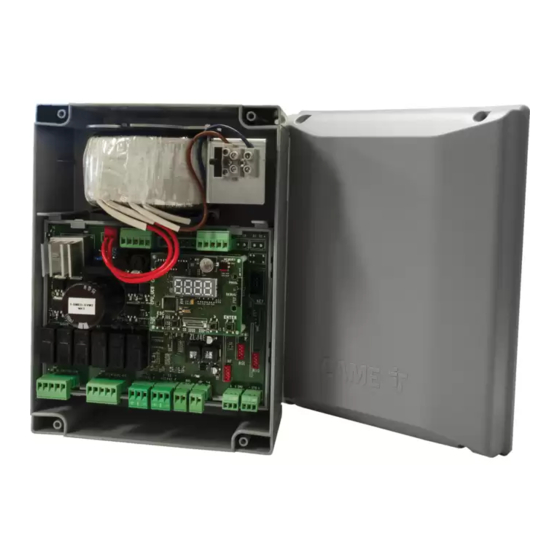
Bornier de connexion des dispositifs de sécurité et/ou encodeurs Connecteur pour carte Memory Roll Bornier de connexion du motoréducteur avec encodeur Connecteur pour CAME KEY ou avec interrupteur de ralentissement et serrure de Affi cheur verrouillage électrique Touches de programmation... - Page 95 Accessoires en option Carte recharge batterie RLB (002RLB) Module RGSM001 (806SA-0010) Module SMA (009SMA)
-
Page 96: Dimensions
Dimensions... -
Page 97: Types De Câbles Et Épaisseurs Minimum
être réévaluées en fonction des absorptions et des distances eff ectives. Pour les connexions de produits non indiqués dans ce manuel, considérer comme valable la documentation jointe à ces derniers. Pour connecter l’encodeur, utiliser un câble type FRORPU 3 x 0,5 mm² ou un câble fourni par la société CAME (code article 801XA-0020). - Page 98 INSTALLATION Préparation de l’armoire de commande...
- Page 99 Fixation de l’armoire de commande Barre DIN Standard...
-
Page 100: Branchements Électriques
BRANCHEMENTS ÉLECTRIQUES Position des câbles électriques Eff ectuer les branchements électriques selon les dispositions en vigueur. Utiliser des passe-câbles pour connecter les dispositifs à l’armoire de commande. Un de ces passe-câbles ne doit être destiné qu’au câble d'alimentation. -
Page 101: Alimentation
Alimentation Branchement au secteur (230/120 VAC - 50/60 Hz) F - Fusible de ligne L - Câble de phase N - Câble neutre Câble de mise à la terre Le collier de fi xation des câbles n'est pas fourni. Sortie alimentation pour accessoires La sortie alimente normalement en 26 VAC. -
Page 102: Motoréducteurs
Alimentation (V) Puissance (W) BUS CXN 15 DC Ne rien connecter d'autre que les accessoires BUS Came. Motoréducteurs M1 =Motoréducteur retardé durant la phase d’ouverture M2 =Motoréducteur retardé durant la phase de fermeture En cas d'installation avec un seul motoréducteur, les branchements électriques doivent être eff ectués sur le motoréducteur (M2). - Page 103 M1 N1 ENC1 EB1+VB M2 N2 ENC2 EB2+VB ATS / AXO / FTX / FAST-70 / AMICO / AXI M2 N2 ENC2 EB2+VB M1 N1 ENC1 EB1+VB STYLO-RME M1 N1 ENC1 EB1+VB M2 N2 ENC2 EB2+VB STYLO-ME...
- Page 104 Motoréducteurs avec interrupteurs de ralentissement FC1 FA1 F FC2 FA2 F M1 N1 ENC1 EB1+VB M2 N2 ENC2 EB2+VB A3024N / A5024N E1 - E2 - M1 N1 ENC1 EB1+VB M2 N2 ENC2 EB2+VB FC1 FA1 F FC2 FA2 F FROG-A24 E1 - E2 -...
- Page 105 Motoréducteurs sans encodeur M2 N2 ENC2 EB2+VB M1 N1 ENC1 EB1+VB...
- Page 106 Dispositifs avec système BUS CXN Le système CXN de CAME est un BUS de communication à 2 fi ls non polarisé permettant de connecter tous les dispositifs CAME compatibles. La connexion au BUS peut être en chaîne, en étoile ou bien mixte.
-
Page 107: Dispositifs De Commande
Dispositifs de commande Bouton d'ARRÊT (contact NF) Arrête le portail et désactive l’éventuelle fermeture automatique. Utiliser un dispositif de commande pour reprendre le mouvement. Si le contact est utilisé, il doit être activé pendant la programmation. Dispositif de commande (contact NO) Fonction OUVERTURE SEULEMENT Avec fonction [ACTION MAINTENUE] activée, la connexion du dispositif de commande en OUVERTURE est obligatoire. -
Page 108: Dispositifs De Signalisation
Dispositifs de signalisation Clignotant Clignote durant les phases d'ouverture et de fermeture de l’automatisme. Lampe supplémentaire Permet d’augmenter l'éclairage de la zone de manœuvre. Voir fonction [Lampe supplémentaire]. Témoin état automatisme Signale l'état de l’automatisme. Voir fonction [Voyant passage ouvert]. 10 11 E E3 5... -
Page 109: Dispositifs De Sécurité
Dispositifs de sécurité Pendant la programmation, confi gurer le type d'action que le dispositif connecté à l'entrée doit eff ectuer. Connecter les dispositifs de sécurité aux entrées CX et/ou CY. En cas d'utilisation des contacts, CX CY les confi gurer en phase de programmation. En cas d'installation avec plusieurs paires de photocellules, consulter le manuel de l'accessoire correspondant. - Page 110 Photocellules DXR - DLX Photocellules DXR - DLX Connexion standard Connexion avec test de sécurité Voir fonction [Test sécurité]. 10 11 E E3 5 10 TS 2 CX CY 10 11 E E3 5 10 TS 2 CX CY 10 11 OUT 10 11 OUT 10 11 SY 10 11 SY...
-
Page 111: Fonction Des Touches De Programmation
PROGRAMMATION Fonction des touches de programmation Touche ESC La touche ESC permet d’eff ectuer les opérations décrites ci-après. Sortir du menu Annuler les modifi cations Revenir à la page-écran précédente Touches < > Les touches <> permettent d’eff ectuer les opérations décrites ci-après. Naviguer dans les options du menu Augmenter ou diminuer une valeur Touche ENTER... -
Page 112: Mise En Fonction
Mise en fonction Au terme des branchements électriques, eff ectuer la mise en marche. L’opération ne doit être eff ectuée que par du personnel qualifi é et spécialisé. S'assurer que la zone de manœuvre ne présente aucun obstacle. Mettre sous tension et programmer. Commencer la programmation par les fonctions suivantes : A1 Type moteur F46 Nombre moteurs... - Page 113 Représentation graphique des vitesses, ralentissements et rapprochements d'un vantail Fin de course en fermeture Vitesse d'ouverture Fin de course en ouverture Vitesse de fermeture Point de ralentissement en ouverture Vitesse de ralentissement en ouverture Point de ralentissement en fermeture Vitesse de ralentissement en fermeture Point de rapprochement en ouverture Vitesse de rapprochement (fi...
-
Page 114: Menu Des Fonctions
Sans utilisation de l'espace de ralentissement (espace de ralentissement = 0) Vitesse d'ouverture ou de fermeture Vitesse de rapprochement (fi xe) Sensibilité obstacles durant la course Fin de course en ouverture ou fermeture Point de rapprochement en ouverture ou fermeture Encodeur virtuel En cas de motoréducteurs sans encodeur ou avec encodeur désactivé, la course est gérée par le biais d'un ENCODEUR VIRTUEL. - Page 115 Entrée CX Associe une fonction à l’entrée CX. OFF (par défaut) C1 = Réouverture durant la fermeture (Photocellules) C2 = Refermeture durant l’ouverture (Photocellules) C3 = Arrêt partiel Uniquement avec [Ferm. automatique] activée. C4 = Attente obstacle (Photocellules) C7 = Réouverture durant la fermeture (Bords sensibles) C8 = Refermeture durant l’ouverture (bords sensibles) C13 = Réouverture durant la fermeture avec fermeture immédiate après l’élimination de l’obstacle, y compris avec portail à...
- Page 116 Action maintenue Avec la fonction activée, le mouvement de l'automatisme (ouverture ou fermeture) est interrompu au relâchement du dispositif de commande. L’activation de cette fonction désactive tous les autres dispositifs de commande. OFF (par défaut) Commande 2-7 Associe une commande au dispositif connecté sur 2-7. 0 = Pas-à-pas (par défaut) 1 = Séquentielle Voyant passage ouvert...
- Page 117 Serrure de verrouillage électrique Permet d’associer le déblocage de la serrure de verrouillage électrique à une commande. OFF (par défaut) 1 = Avec portail fermé 2 = Avec portail ouvert 3 = Avec portail ouvert et portail fermé 4 = Continuer Lampe supplémentaire Permet de choisir le mode de fonctionnement du dispositif d'éclairage connecté...
- Page 118 Temps de retard à la fermeture de M2 Confi gure le retard à l'ouverture du deuxième vantail par rapport au premier. De 1 à 25 secondes (par défaut 2) Temps accueil Défi nit pendant combien de secondes la lampe supplémentaire (confi gurée comme lampe d'accueil) reste allumée après une manœuvre d'ouverture ou de fermeture.
- Page 119 AST contrôle au ralentissement Règle la sensibilité de détection des obstacles, en pourcentage, durant la phase de ralentissement. Ce paramètre n'est utilisé que si le point de ralentissement en fermeture ou en ouverture est activé. de 10 % à 100 % (par défaut 100 %) 10 % = poussée minimum et haute sensibilité...
- Page 120 Point de rapprochement en ouverture de M2 Permet de confi gurer le pourcentage de la course totale à utiliser pour le rapprochement à l'ouverture de M2. De 0,5 % à 25,0 % (par défaut 8,0 %) Point de rapprochement en fermeture de M2 Permet de confi...
- Page 121 Confi guration de l'entretien Permet de défi nir le nombre de manœuvres que l’automatisme peut exécuter avant que la nécessité d’eff ectuer la maintenance ne soit notifi ée. La notifi cation est affi chée à l'écran moyennant le message [SEr] et signalée toutes les heures par 3 + 3 clignotements provenant du dispositif connecté...
- Page 122 RIO PH T1 Permet d'associer une fonction parmi celles prévues à un dispositif de sécurité sans fi l. La fonction n'apparaît qu'en présence de la carte d'interface RIO Conn. OFF (par défaut) P1 = Réouverture durant la fermeture. P2 = Refermeture durant l’ouverture. P3 = Arrêt partiel.
- Page 123 Mode sans obstacle En cas de détection d'un obstacle moyennant l’AST control de la carte ou par l'entrée d'un bord, la fonction [Mode sans obstacle] inverse la direction du vantail uniquement sur l'espace nécessaire pour dégager l'obstacle puis s'arrête. OFF = Inversion pour obstacle (par défaut) ON = Mode sans obstacle Nouvel utilisateur Permet d'enregistrer jusqu'à...
- Page 124 Auto-apprentissage Rolling Permet de mémoriser un nouvel émetteur rolling code en activant l'acquisition à partir d'un émetteur à code tournant déjà mémorisé. Les procédures de mémorisation et d'acquisition sont expliquées dans le manuel de l'émetteur. OFF (par défaut) Type moteur Confi...
- Page 125 Comptage manœuvres Permet de visualiser le nombre de manœuvres eff ectuées par l’automatisme, totale ou partiel (après une opération d'entretien). Le nombre de manœuvres est le nombre visualisé multiplié par 100. Tot = manœuvres totales Manœuvres eff ectuées à compter de l'installation de l'automatisme. Par = manœuvres partielles Manœuvres eff ectuées après le dernier entretien.
- Page 126 État dispositifs BUS Indique l'état de tous les dispositifs pouvant être connectés au BUS et gérés par le fi rmware utilisé. Légende État du dispositif <x> b = Photocellules BUS || = Adresse en confl it d = Sélecteur BUS o = En fonction L = Clignotant BUS c = En fonction avec signal d'alarme...
- Page 127 Clignotant BUS <Couleur en ouverture> Permet de confi gurer la couleur del clignotant BUS durant l'ouverture du portail. La fonction n'apparaît qu'en présence d'un clignotant BUS connecté. Lors du calcul qui précède la fermeture automatique, la couleur du clignotant est la même que pendant l'ouverture.
- Page 128 2 = Jaune 3 = Orange 4 = Rouge 5 = Violet 6 = Bleu 7 = Bleu ciel 8 = Vert Avec le dispositif CAME KEY, toujours mettre à jour le fi rmware de la carte à la dernière version disponible.
-
Page 129: Exporter / Importer Les Données
Exporter / importer les données Il est possible d’enregistrer les données des utilisateurs et de la confi guration de l'installation dans une carte MEMORY ROLL. Les données stockées peuvent être réutilisées dans une autre carte électronique du même genre pour adopter les mêmes confi... -
Page 130: Messages D'erreur
MESSAGES D'ERREUR Erreur de réglage du moteur M1 Erreur de réglage du moteur M2 Erreur signal encodeur non détecté Erreur test services échoué Erreur temps de fonctionnement Obstacles consécutifs détectés durant la fermeture Obstacles consécutifs détectés durant l’ouverture Erreur maximum obstacles Tension d’alimentation du moteur absente ou insuffi sante Erreur sur les entrées fi... -
Page 131: Opérations Finales
OPÉRATIONS FINALES Avant de fermer le couvercle, s'assurer que l'entrée des câbles est bien scellée de manière à éviter la pénétration d'insectes ainsi que la formation d'humidité. - Page 132 COLLER ICI L'ÉTIQUETTE DU PRODUIT PRÉSENTE SUR L'EMBALLAGE CAME S.p.A. Via Martiri della Libertà, 15 31030 Dosson di Casier Treviso - Italy Tél. (+39) 0422 49 40 Fax (+39) 0422 49 41...
-
Page 133: Руководство По Монтажу
Блок управления для приводов 24 В FA01578-RU ZLX24MA ZLX24MR РУКОВОДСТВО ПО МОНТАЖУ Русский... - Page 134 для обеспечения соответствия конечной установки Директиве о безопасности машин и оборудования 2006/42/CE и гармонизированным техническим стандартам, указаны в общем каталоге продукции CAME или на сайте www. came.com. • Убедитесь в том, что указанный диапазон температур соответствует температуре окружающей среды в месте установки. • Убедитесь в том, чтобы...
- Page 135 • Прежде чем продолжать установку, убедитесь в том, что движущиеся компоненты оборудования находятся в надлежащем механическом состоянии, открываются и закрываются правильно. • Изделие не может использоваться с подвижным ограждением, оборудованным пешеходной калиткой, за исключением ситуации, когда движение ограждения возможно только при безопасном...
- Page 136 прейскурантах Came. УТИЛИЗАЦИЯ CAME S.p.A. имеет сертификат системы защиты окружающей среды UNI EN ISO 14001, гарантирующий экологическую безопасность на ее заводах. Мы просим вас прилагать максимальные усилия по защите окружающей среды. Компания САМЕ считает одним из фундаментальных пунктов стратегии рыночных отношений выполнение этих...
- Page 137 Все размеры приведены в мм, если не указано иное. Описание 801QA-0050 ZLX24MA - Многофункциональный блок управления с питанием ~230 В для двустворчатых распашных ворот 24 В с дисплеем для программирования, функцией самодиагностики устройств безопасности, технологией адаптивного управления скоростью и крутящим моментом, шиной CXN, 2 входными контактами безопасности и возможностью...
-
Page 138: Описание Компонентов
Контакты подключения устройств управления Контакты для подключения концевых Контакты подключения устройств безопасности микровыключателей и/или энкодеров Разъем для карты памяти Контакты для подключения электропривода Разъем для CAME KEY с энкодером или с выключателем замедления и Дисплей электрозамком Кнопки программирования Предохранитель для дополнительных устройств... - Page 139 Дополнительные аксессуары Плата подзарядки аккумуляторов RLB (002RLB) Модуль RGSM001 (806SA-0010) Модуль SMA (009SMA)
-
Page 140: Габаритные Размеры
Габаритные размеры... - Page 141 руководствоваться технической документацией на соответствующее изделие. Для подключения энкодера используйте кабель типа FRORPU 3 x 0,5 мм2 или кабель, предоставляемый компанией CAME (артикул изделия 801XA-0020). Таблица кабелей шины: Рекомендуется использовать кабель FROR 2x1 мм² длиной не более 50 м от платы управления.
- Page 142 МОНТАЖ Подготовка блока управления к монтажу...
- Page 143 Монтаж блока управления DIN-рейка Стандартная...
-
Page 144: Электрические Подключения
ЭЛЕКТРИЧЕСКИЕ ПОДКЛЮЧЕНИЯ Подготовка электрокабелей Выполните электрические подключения в соответствии с действующими нормами. Для подключения устройств к блоку управления используйте гермовводы. Один из гермовводов должен быть предназначен непосредственно для кабеля электропитания. - Page 145 Электропитание Подключение к сетевому электропитанию (~120/230 В, 50/60 Гц) F - Входной предохранитель L - Фазный провод N - Нулевой провод Провод заземления Хомут для фиксации кабелей не входит в комплект поставки. Выход электропитания аксессуаров Выход стандартного питания ~26 В. Выход обеспечивает =24 В (10+, 11-) при электропитании от аккумуляторов (при их наличии). Подключение...
- Page 146 Устройство Выход Мощность (Вт) (В) ШИНА CXN ШИНА Разрешается подсоединять только шинные устройства Came. Приводы M1 =Привод с задержкой при открывании M2 =Привод с задержкой при закрывании Если система состоит из одного привода, электрические подключения должны выполняться на приводе (M2).
- Page 147 Приводы с энкодером E1 - E2 - M1 N1 ENC1 EB1+VB M2 N2 ENC2 EB2+VB FC1 FA1 F FC2 FA2 F FROG-A24E / FERNI / FERNI-V / F4024E / F4024EP M1 N1 ENC1 EB1+VB M2 N2 ENC2 EB2+VB ATS / AXO / FTX / FAST-70 / AMICO / AXI M1 N1 ENC1 EB1+VB M2 N2 ENC2 EB2+VB STYLO-RME...
- Page 148 M1 N1 ENC1 EB1+VB M2 N2 ENC2 EB2+VB STYLO-ME Приводы с выключателями замедления FC1 FA1 F FC2 FA2 F M2 N2 ENC2 EB2+VB M1 N1 ENC1 EB1+VB A3024N / A5024N E1 - E2 - M1 N1 ENC1 EB1+VB M2 N2 ENC2 EB2+VB FC1 FA1 F FC2 FA2 F FROG-A24...
- Page 149 E1 - E2 - M2 N2 ENC2 EB2+VB M1 N1 ENC1 EB1+VB FC1 FA1 F FC2 FA2 F F1024 Приводы без энкодера M1 N1 ENC1 EB1+VB M2 N2 ENC2 EB2+VB...
- Page 150 Устройства, подключаемые к ШИНЕ CXN Система CXN CAME представляет собой 2-проводную неполяризованную шину, позволяющую соединять все совместимые устройства CAME. Соединение с шиной может быть следующим: последовательным, звездой или смешанным. После выполнения кабельной проводки системы и настройки адреса на каждом устройстве можно задать функцию...
-
Page 151: Устройства Управления
Устройства управления Кнопка «СТОП» (нормально-замкнутые контакты) Останавливает ворота и отменяет последующий цикл автоматического закрывания. Для возобновления движения необходимо использовать соответствующее устройство управления. Если этот контакт используется, его следует активировать на этапе программирования. Устройство управления (нормально-разомкнутые контакты) Функция «ТОЛЬКО ОТКРЫТЬ» При активной функции [ПРИСУТСТВИЕ ОПЕРАТОРА] необходимо подключить устройство управления для ОТКРЫВАНИЯ. - Page 152 Устройства сигнализации Сигнальная лампа Мигает во время открывания и закрывания автоматики. Вспомогательная лампа Увеличивает освещенность зоны проезда. См. функцию [Вспомогательная лампа]. Лампа-индикатор состояния автоматики Обозначает состояние автоматики. См. функцию [Индикатор открытия ворот]. 10 11 E E3 5...
- Page 153 Устройства безопасности На этапе программирования настройте действие, которое должно выполняться подключенным к контактам устройством. Подключите устройства безопасности ко входам CX и/или CY. Если контакты используются, CX CY их необходимо настроить на этапе программирования. Если в системе установлено несколько комплектов фотоэлементов, ознакомьтесь с инструкцией на соответствующий...
- Page 154 Фотоэлемент DXR - DLX Фотоэлемент DXR - DLX Стандартное подключение Подключение с диагностикой См. функцию [Диагностика устройств безопасности]. 10 11 E E3 5 10 TS 2 CX CY 10 11 E E3 5 10 TS 2 CX CY 10 11 OUT 10 11 OUT 10 11 SY 10 11 SY...
- Page 155 ПРОГРАММИРОВАНИЕ Функции кнопок программирования Кнопка ESC Кнопка ESC позволяет выполнить нижеописанные действия. Выйти из меню Отменить изменения Вернуться на предыдущую страницу Кнопки < > Кнопки < > позволяют выполнить нижеописанные действия. Навигация по пунктам меню Увеличение или уменьшение значения выбранного параметра Кнопка...
-
Page 156: Ввод В Эксплуатацию
Ввод в эксплуатацию После выполнения всех электрических подключений переходите к вводу системы в эксплуатацию. Операцию должен выполнять только компетентный и квалифицированный персонал. Убедитесь в том, что в зоне действия автоматики отсутствуют препятствия. Подайте напряжение и выполните программирование. Начните программирование с настройки следующих функций: A1 Модель... - Page 157 Графики скорости движения, замедления и остановки створки Концевой выключатель закрывания Скорость открывания Концевой выключатель открывания Скорость закрывания Начало замедления при открывании Скорость замедления при открывании Начало замедления при закрывании Скорость замедления при закрывании Начало остановки привода при открывании Скорость остановки (фиксированная) Начало...
- Page 158 Без использования пространства для замедления (пространство для замедления = 0) Скорость открывания или закрывания Скорость остановки (фиксированная) Чувствительность системы обнаружения препятствий при движении Концевой выключатель открывания или закрывания Начало остановки при открывании или закрывании Виртуальный энкодер Для приводов без энкодера или с отключенным энкодером управление движением обеспечивается ВИРТУАЛЬНЫМ ЭНКОДЕРОМ.
- Page 159 Входные контакты CX Позволяет закрепить за контактами CX одну из доступных функций. OFF (по умолчанию) C1 = Открывание в режиме закрывания (фотоэлементы) C2 = Закрывание в режиме открывания (фотоэлементы) C3 = Частичная остановка Только при включенной функции [Авт. закрывание]. C4 = Обнаружение препятствия (фотоэлементы) C7 = Открывание...
- Page 160 Присутствие оператора При включении этой функции движение ворот (открывание или закрывание) прерывается, когда прекращается нажатие соответствующей кнопки управления. Активация этой функции блокирует все другие устройства управления. OFF (по умолчанию) Команда 2-7 Присваивает команду управления устройству, подключенному к контактам 2-7. 0 = Пошаговый режим (по умолчанию) 1 = Последовательный...
- Page 161 Электрозамок Позволяет назначить команду для разблокировки электрозамка. OFF (по умолчанию) 1 = В закрытом положении 2 = В открытом положении 3 = В открытом и закрытом положении 4 = Продолжить Вспомогательная лампа Позволяет выбрать режим работы осветительного устройства, подключенного к выходу Е3. OFF (по...
- Page 162 Время задержки при открывании М1 Регулирует задержку при открывании первой створки относительно второй. От 1 до 10 секунд (по умолчанию 2) Время задержки при закрывании М2 Регулирует задержку при открывании первой створки относительно второй. От 1 до 25 секунд (по умолчанию 2) Время...
- Page 163 Система управления AST при движении Функция регулирует чувствительность системы обнаружения препятствий (в процентном отношении) во время движения. от 10% до 100% (по умолчанию 100%) 10% = минимальный дожим и высокая чувствительность обнаружения препятствий 100 % = максимальный дожим и низкая чувствительность обнаружения препятствий...
- Page 164 Начало остановки привода M1 при закрывании Устанавливает конечную фазу замедления створки M1 при закрывании в процентном отношении ко всей траектории движения. От 0,5% до 25,0% (по умолчанию 8,0%) Точка замедления при открывании М2 Устанавливает точку начала замедления створки М2 при открывании в процентном отношении ко всей траектории движения.
- Page 165 Сохранение данных Сохраняет в запоминающем устройстве (карте памяти) данные, относящиеся к пользователям, параметрам времени и настройкам. Функция отображается только тогда, когда карта памяти вставлена в плату управления. ON (выполняет операцию) Считывание данных Загружает из запоминающего устройства (карты памяти) данные, относящиеся к пользователям, выдержке времени и...
- Page 166 RIO ED T1 Позволяет присвоить одну из предусмотренных функций беспроводному устройству безопасности. Функция доступна только при наличии интерфейсной платы RIO Conn. OFF (по умолчанию) Р0 = Останавливает ворота и отменяет последующий цикл автоматического закрывания. Для возобновления движения необходимо использовать соответствующее устройство управления. P7 = Открывание...
- Page 167 Функция конц. выключателей Устанавливается режим работы входов для выключателей замедления/концевых выключателей. Функция доступна только для моторов, в которых она предусмотрена. После изменения функции контактов замедления/концевых выключателей потребуется выполнить калибровку [Функция A3]. В случае использования входов для замедления, по завершении калибровки плата автоматически настроит...
- Page 168 Удаление пользователя Удаляет одного из зарегистрированных пользователей. Количество: 1 > 250 Стрелками выберите номер пользователя, которого желаете удалить. В качестве альтернативы можно активировать устройство управления, связанное с пользователем, которого требуется удалить. Подтвердите, нажав ENTER. Появится надпись «CLr», подтверждающая удаление. Удалить всех пользователей Удаляет...
- Page 169 Тест привода Проверка направления открывания створок ворот. При активированной функции кнопка > открывает створку, подключенную к M2, а кнопка < открывает створку, подключенную к M1. Движение продолжается до тех пор, пока нажата кнопка, или до упора крайнего положения. Если кнопку отпустить, движение остановится. Если...
- Page 170 Версия прошивки Функция позволяет отображать версию установленной прошивки и графического пользовательского интерфейса. Используйте стрелки < > для последовательного просмотра версии платы дисплея и версии платы управления. Активировать пароль Позволяет настроить 4-значный пароль. Пароль будет запрашиваться при каждой попытке входа в меню. OFF (по...
- Page 171 Фотоэлемент ШИНЫ <n> Позволяет связать с входом Фотоэлемент ШИНЫ <n> одну из доступных функций. <n> составляет от 1 до 8 и соответствует адресу, заданному на dip-переключателе фотоэлемента b1÷b8 OFF (по умолчанию) C1 = Открывание в режиме закрывания (фотоэлементы) C2 = Закрывание в режиме открывания (фотоэлементы) C3 = Частичная...
- Page 172 Сигнальная лампа ШИНЫ <Цвет при закрыв.> Устанавливает цвет сигнальной лампы ШИНЫ во время закрывания ворот. Функция доступна только при наличии подключенной сигнальной лампы ШИНЫ. b40 > 1 = Белый (по умолчанию) 2 = Желтый 3 = Оранжевый 4 = Красный 5 = Фиолетовый...
- Page 173 0 = Отключено (по умолчанию) 1 = Белый 2 = Желтый 3 = Оранжевый 4 = Красный 5 = Фиолетовый 6 = Синий 7 = Голубой 8 = Зеленый Всегда обновляйте прошивку платы до последней доступной версии с помощью CAME KEY.
- Page 174 Экспорт / импорт данных Данные, относящиеся к пользователям и настройкам системы, можно сохранить на КАРТЕ ПАМЯТИ. Сохраненные данные можно снова использовать повторно на другой плате управления той же модели для установки аналогичных настроек. ОТКЛЮЧИТЕ ЭЛЕКТРОПИТАНИЕ перед установкой или извлечением КАРТЫ ПАМЯТИ. Вставьте...
-
Page 175: Сообщения Об Ошибках
СООБЩЕНИЯ ОБ ОШИБКАХ Ошибка калибровки двигателя М1 Ошибка калибровки двигателя М2 Ошибка сигнала энкодера Ошибка сбоя самодиагностики Ошибка времени работы Обнаружение препятствий при закрывании Обнаружение препятствий при открывании Ошибка из-за максимального количества препятствий Напряжение электропитания привода отсутствует или недостаточно Ошибка на входных контактах концевых выключателей или контакты обоих концевых выключателей... -
Page 176: Заключительные Работы
Перед закрытием крышки следует убедиться в герметичности входа кабелей, чтобы предотвратить попадание насекомых и образование влаги. ПРИКЛЕЙТЕ ЗДЕСЬ ЭТИКЕТКУ ИЗДЕЛИЯ, ПРИЛАГАЕМУЮ В УПАКОВКЕ CAME S.p.A. Via Martiri della Libertà, 15 31030 Доссон-ди-Казьер Treviso - Italy (Италия) Тел.: (+39) 0422 4940...