ABB RVT6 Instructions D'installation, D'utilisation Et D'entretien

Manuels Connexes pour ABB RVT6


Sommaire des Matières pour ABB RVT6
- Page 1 — INSTRUCTION MANUAL Power Factor Controller RVT Installation and operating instructions Instructions d’installation, d’utilisation et d’entretien Installations und Betriebsanleitung Instrucciones de instalación y de funcionamiento RVT安装和操作说明 Instruções de instalação e operação...
- Page 2 Installation and operating instructions...
- Page 3 — Table of contents Read this first ................................. 4 About this instruction manual ..........................4 Warning ..................................4 Safety ..................................4 Electromagnetic compatibility ..........................4 1 Introduction to the controller ........................6 1.1 What this chapter contains ........................... 6 1.2 A fully three phase individual controlled power factor controller ............6 1.3 RVT main features ............................
- Page 4 4.5 Communications ............................56 4.5.1 I/O configuration ............................60 4.5.2 Ethernet configurations ........................... 63 4.5.3 Screen configuration ..........................63 4.5.4 About ................................65 4.5.5 Mac Address ............................... 65 Appendices ................................66 A1. Dimensions ..............................66 A2. Technical specifications ..........................66 A3.
-
Page 5: Read This First
— Read this first About this instruction manual This Instruction Manual provides detailed information to help you quickly install and operate the RVT power factor controller. Warning Caution, risk of danger: This symbol is a warning indication to highlight some important information Before installation and operation of the RVT controller, read the safety notices carefully. - Page 6 improving the EMC performance of a system: Metallic enclosures generally improve EMC performance. 1. Run cables away from apertures in the enclosure. 2. Run cables close to grounded metallic structures. 3. Use multiple ground straps for doors or other panel parts as required. 4.
- Page 7 There are two models for RVT controllers: RVT Base Model RVT6/RVT12 and RVT Three Phase Model RVT12-3P. The Base Model is fully backward compatible to previous RVT controllers with 6 or 12 outputs, which is applicable for a balanced three phases or single phase (phase to phase) network.
- Page 8 Logging of data and alarm messages based on a real time clock (description in paragraphs 4.2.5 and 4.4). Checking and testing of relays status (description in paragraphs 4.4.2 and 4.4). Temperature measurements: max. 8 temperature probes can be connected in daisy chain connection (description in paragraph 4.3.1.4.3).
- Page 9 Figure 2: RVT rear View (Base Model RVT6/RVT12) Figure 3: RVT rear View (Three Phase Model RVT12-3P) 8 Introduction ç Manual Power Factor Controller RVT...
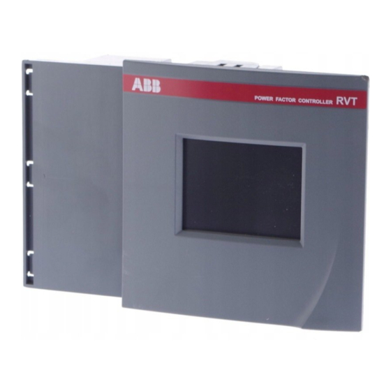
- Page 10 1.5 Colorful touch screen interface A colorful QVGA 320 x 240 pixels touch screen helps the user to operate the controller more easily. All the menu navigations, parameters settings are easy and intuitive thanks to the touch screen. Figure 4: RVT start screen Detailed Menu navigation can be found in Paragraph Manual Power Factor Controller RVT ç...
- Page 11 — 2 Installation 2.1 What this chapter contains This chapter gives instructions to mount the controller on the panel and explains how to make the electrical connection to the controller. The wiring diagram is shown in section 2.4. 2.2 Mounting Please follow steps below to mount a RVT controller to a panel.
- Page 12 Step 4 Step 3 Step 5 Repeat steps 3 to 5 for the bottom Mounting Bracket. Figure 6: Mounting a RVT 2.3 Lead connections Please follow instructions below to connect wires to the terminals on the rear side of the controller.
-
Page 13: Wiring Diagram
4. The wire is properly connected. Figure 10: Lead connection 2.4 Wiring diagram The wiring diagram shows the connection of main circuits and control circuits. Base model RVT6/RVT12 Figure 11: RVT wiring diagram (base model RVT6/RVT12) 12 Installation ç Manual Power Factor Controller RVT... - Page 14 Three phase model RVT12-3P Figure 12: RVT wiring diagram (three-phase model RVT12-3P) PS1, 2 Power supply ML1-3 Voltage measurements N.C. Not connected Neutral connection k1-3, I1-3 CT connections canH, canL CAN bus Earth Grounding Temp Temperature probe connection RS485 Modbus Adapter RS485 interface IN1+/- digital input selecting Day or Night target cos j IN2+/- digital input for external alarm activation...
-
Page 15: Easy Start
This chapter describes briefly the quick start and automatic commissioning procedure for the controller. 3.2 Menu navigation When the RVT is switched on power after the boot process (where the ABB logo is displayed) the start screen is the first screen which will be displayed as shown in Figure... - Page 16 settings can only be done through the communication settings can be done through the user interface or the communication temperature alarm ( alarm relay is activated ) or warning ( fan/warning relay is activated ) no temperature alarm nor warning ( alarm and fan/warning relays are not activated ) warning level achieved ( the fan/warning relay is activated ) alarm activated ( alarm relay is activated )
-
Page 17: Status Bar
Title bar Setting area Status bar Figure 14: RVT screen composition 3.2.2 Title bar At the left end of the title bar, the blue Mode button is used to switch between the three RVT operating modes: Automatic mode, Manual mode and Set mode. The following screen as shown in Figure 15 appears when the Mode button is clicked. - Page 18 Figure 16: RVT help information Clicking the Red Cross button at the right end of the title bar the current active screen will be closed. Note: The RVT returns automatically to AUTO mode when the touch screen is not touched for more than five minutes. 3.2.3 Setting area The setting area consists of buttons, setting and information fields.
- Page 19 Figure 17: Keyboard entry screen Cos j values may be entered with the (inductive) or (capacitive) symbol. 3.3 Starting the RVT When the RVT is powered-up, the start screen as shown in Figure 13 will be displayed. There are four big icons on the start screen: Measurements, Settings, Bank monitoring and Communication.
- Page 20 · Phase shift and rotation for each predefined type of connection · number of outputs · type of switching sequence Automatic setting of: C/k, the start current, detailed description on C/k can be found in paragraph 4.3.1.2. 3.4.2 Preparation for automatic commissioning Required parameters during the auto commissioning process are: Type of connection.
- Page 21 1. Start screen, Click “Settings”: 2. Click commissioning: 3. Click automatic: 4. Click OK: 5. Click OK: 6. Select type of connection (refer to Appendix7) 20 Easy start ç Manual Power Factor Controller RVT...
- Page 22 7. Click OK: 8. Lock or unlock the “Bank settings - OK: 9. Click OK: 10. Click OK: 11. Input CT scaling: 50: 12. Click OK: Manual Power Factor Controller RVT ç Easy start 21...
- Page 23 13. Click OK: 14. Click OK: 15. Click OK: 16. Click OK: 17. Click OK: 18. Click OK: 22 Easy start ç Manual Power Factor Controller RVT...
- Page 24 19. Click OK: 20. Click OK: 21. Automatic commissioning completed: The above process is a typical automatic commissioning. Some setting like the CT ratio and type of connection could be different from above inputs for each installation. In case some errors occur during the automatic commissioning, the help info will instruct the user to identify the causes and complete the commissioning.
- Page 25 — 4 Measurements and Settings 4.1 What this chapter contains This chapter describes all the menus/submenus for measurements, settings, bank monitoring and communications settings, etc. 4.2 Measurements This main menu allows the user to see various parameters like voltage, current, power, temperature.
- Page 26 Event Logging This submenu allows the user to view the extreme values of some key parameters. Meter This function offers a possibility for the user to display three most concerned measurements in one screen. For instance, three line voltages can be shown in one screen in a better resolution and better view.
- Page 27 Missing Q Missing power to reach the 0 è 10 ± 2% 0 è 10 pre-set alarm cos j Missing Steps Missing capacitor steps to reach the pre-set alarm cos j Temperature (optional) Range Accuracy Max value T1-T8 °C/° Temperature T1-T8 (optional -40°C è...
- Page 28 The user may customize the display of the measurement values to his particular needs just by moving the important items in the list to a desired position. Click on the item in the list to be moved (in the below example, the THDV L-L is chosen) Item to move Then click on the position where the item in the list should be moved (in the example...
- Page 29 Switch ON and buttons Then, “Switch ON and OFF 1 step” buttons are enabled. Click on these buttons to switch steps manually. Note: The RVT12-3P model will enter a new screen asking which kind of step should be (de)activated. Differences between these steps can be found in 4.3.1.1.
- Page 30 Voltage (current) measurements Display harmonic table and Voltage (current) harmonic chart and table Harmonics voltage/current can be illustrated in bar chart as shown below. A scrolling bar is to choose a specific harmonic to display at the top of the screen: the harmonic order, the value and percentage against Fundamental.
- Page 31 Select measurement to display Figure 20: Harmonics voltage in table Comment: accuracy on voltage (current) harmonic measurements: ± 1 % of Vrms (Irms) Power, Power factor measurements 30 Measurements and Settings ç Power Factor Controller RVT...
-
Page 32: Temperature Measurements
Temperature measurements Energy measurements Reset energy values Energy measurements are only available on the RVT12-3P (the 3 phase model is equipped with a real time clock). Energy values may be “Reset” to 0. 4.2.3 Waveform Available voltage and current signals (depending on RVT type and connection used) and the line current can be displayed on the screen as waveforms. -
Page 33: Event Logging
4.2.4 Meter This function offers the user a better view of three most interested measurements. Click on the wanted item, and then click the “Select” button to insert values in the meter screen. An example is shown below for three important measurements. Figure 22: three measurements displayed in meter 4.2.5 Event logging... - Page 34 Maximum recorded Threshold Total duration = t1 + t2 + t3 Time Recorded values The event logging function allows the user to record the time during which a measured value exceeds a threshold and its maximum value for the following parameters : Vrms [V], Irms [A], P [kW], Q [kvar], S [kVA], THDV [%], THDI [%], missing Q [kvar], frequency* [Hz], T1* [°C or °F] to T8* [°C or °F].
- Page 35 Figure 25: Event logging threshold setting - Frequency The recorded information (maximum value and total duration) may be cleared by selecting and validating the “Reset” button. 4.3 Settings The main menu Settings has multi-level submenus allowing the user to program the controller as well as to do commissioning and test functions.
- Page 36 4.3.1 Manual settings (Set Mode) The manual settings allow the user to access all the Bank, Installation, User settings and protection/warning configurations. The user can also restore the factory setting from this sub-menu. Figure 26: Manual settings Before making any settings to the controller, please make it is in Set mode. Please refer 3.2.4 and 4.3.1.1.
- Page 37 *Sequence: relative reactive power value of the capacitors connected to the RVT outputs. These relative values are included between 0 and 8. For both Base Model RVT6/RVT12 and Three Phase Model RVT12-3P, the default factory sequence is: 1:1:….:1. Customized sequence may be introduced manually.
- Page 38 1, 2 or 3 respectively. “3Ph”: this output controls a 3 phase capacitor. For a Base Model RVT6/RVT12, only “Fixed OFF, Fixed ON and Enabled” are available for the output status. An output need to be set “Enabled” before the controller switches on or off a capacitor.
- Page 39 Figure 30: Typical outputs setting 12 x 1ph (Three phase model RVT12-3P) Typical setting two: 6 steps of three phase capacitors + 6 steps of single phase (phase to neutral) capacitors: Figure 31: Typical outputs setting 6 x 3ph + 6 x 1ph (Three phase model RVT12-3P) Delay Click the button “Delay”...
- Page 40 CT connection topologies based on the type of network (three phase three wire network, three phase four wire network or single phase network (phase to phase): One phase current measurement (available for both base mode RVT6/12 and RVT12- 3P):1Ph-1LL1, 3Ph-1LL1, 3Ph-1LN1. Power Factor Controller RVT ç Measurements and Settings 39...
- Page 41 Three phase current measurements (available only for three phase model RVT12-3P): 3Ph-3LL3, 3Ph-3LL2 (no neutral connection connected in the installation), 3Ph-3LN3, 3Ph- 1LL3, 3Ph-1LN3. 40 Measurements and Settings ç Power Factor Controller RVT...
- Page 42 Detailed instruction of the connection can be found in A7. CT connection type illustration and CT wiring on the controller terminals in the appendix section at the end of this manual. Definition of above type of connections: 3Ph – 3 LN 3 1: one CT connection, 2: two CTs connections, 3: three CTs connections LN: V measurement between L and N, LL V measurement between phases 1: one V measurement, 3: three V measurements...
- Page 43 n Output closed o Output open Progressive / Direct (Prog./Direct on the screen) Progressive operation switches the steps sequentially one by one, based on ON-Delay value. Direct operation switches the biggest steps first then the other steps with a fixed delay of 12s, to reach the target cos j faster.
- Page 44 Integral = Switching on one step no step Normal = Switching delay time no step No switching Bank setting protection (Software lock) The bank settings can be protected from unauthorized access by both hardware and software. The hardware protection is described in 3.2.4.
-
Page 45: Installation Settings
The controller is locked by software. Figure 35: RVT bank settings protection: protected 4.3.1.2 Installation settings Start screen-> Settings-> Manual settings-> installation settings RVT installation settings give instructions on how to set CT related parameters. Figure 36: RVT installation settings CT scaling: current transformer ratio. - Page 46 0.15 0.19 Note: For RVT12-3P, two C/k are available: C/k 1ph and C/k 3ph; RVT6/RVT12 has only C/k available. C/k 3ph (or C/k) is applicable for installation with one, two or three CT (three phase balanced network); C/k 1ph is applicable for installation with three CTs (unbalanced three phase network).
-
Page 47: User Settings
For other connection, the phase shift to be programmed can be selected from the tables in the appendix A6. Please note that the RVT can adapt automatically the phase shift during automatic commissioning. 4.3.1.3 User settings Start screen-> Settings-> Manual settings-> user settings User Settings allows the users to set different target power factors and alarm delays. - Page 48 Alarm: alarm relay parameters can be set for the Alarm cos j condition: The Alarm cos j condition is fulfilled when: all the capacitor steps are ON and the actual cos j value is below the alarm cos j threshold value such that at least one step is needed. Alarm delay: duration of alarm cos j condition before the relay closes.
- Page 49 protection initiated by the opto-isolated input 2. The alarm relay provides one NO and one NC contact. Once a protection level is reached, the following actions occur: all the capacitor steps are switched off an alarm message appears on the display the alarm relay is activated ( NO opens / NC closes ) the icon is highlighted...
- Page 50 4.3.1.4.3Temp protections RVT provides 8 bank temperature protections by eight temperature probes. Each temperature probe protection level can be set independently. When any one of the eight the temperature protection levels is reached. all the capacitor steps are switched off an alarm message appears on the display the alarm relay is activated ( NO opens / NC closes ) the icons...
-
Page 51: Restore Default Settings
Note 1: the RVT is self-protected against an internal over-temperature of 85°C. The actions described above will occur when the internal temp exceeds this protection level. The RVT will restart automatically when the internal temperature falls back below 80°C. Note 2: the temperature protection levels are disabled by default. When a level is entered, the RVT checks one of the eight probe connections. - Page 52 4.3.2.1 Automatic Commissioning Please refer to section for more details. 4.3.2.2 Guided Commissioning The RVT performs a guided commissioning process. The following parameters (see table below) must be entered. Note: Before performing guided commissioning, please make sure that: 1. RVT is unlocked (description in paragraphs 3.2.4 and 4.3.1.1) 2.
- Page 53 V nom Nominal bank voltage. ON-Delay Switching ON delay time. OFF-Delay Switching OFF delay time. Sequence Relative reactive power value of each output. Q step Smallest reactive power difference between steps. Set the starting current Target cos j Target displacement power factor. 4.3.2.3 T Probes commissioning RVT can connect up to eight temperature probes in a daisy chain.
- Page 54 Connect each probe successively : Wire - Wire D Wire - Wire D 4.4 Bank Monitoring RVT bank monitoring gives user the access to the diagnosis, alarm logging, test function and a real time clock (only the three phase model RVT12-3P has the real time clock). This makes a very helpful diagnostic tool.
-
Page 55: Test Function
Figure 47: Bank monitoring diagnosis 4.4.2 Test function This sub-menu allows the user to test each relay of the RVT. Test alarm: allows testing of the alarm relay Test fan: allows testing of the fan/warning relay Test outputs: allows testing of each output capacitor relay (the RVT will take care of the programmed switching delays) Figure 48: Bank monitoring test function 54 Measurements and Settings ç... - Page 56 Figure 49: Bank monitoring test outputs Click on the check box to switch ON/OFF the corresponding relay Before proceeding to the test functions, please make sure that: RVT is unlocked (description in paragraphs 3.2.4 and 4.3.1.1) RVT is in SET mode (description in paragraph 3.2.2.) 4.4.3 Alarm logging The alarm logging displays the last five alarm messages with a real time stamp.
- Page 57 4.4.4 Real time clock Figure 51: RVT real time clock The real time clock continues to run even when the RVT is not connected to the power. 4.5 Communications RVT provides a variety of communications methods. In this main menu, it includes the language setting, temp unit setting, screen configuration and settings for Ethernet, Modbus.
- Page 58 RS485 / Modbus Adapter The Modbus adapter is an optional device for the Power Factor Controller RVT which enables the connection of the RVT to a RS485 Modbus system. The controller is considered as a slave unit in the Modbus network. Refer to the 2GCS214013A0050-RVT Modbus RS485 adapter-User guide for more information on the RS485 Modbus Adapter.
- Page 59 Ethernet / TCP/IP TCP/IP connections can be indifferently initiated locally or remotely. The TCP port used by default is 4250. The connection to the RVT is an RJ45 Cat5e Ethernet cable. The RVT can be connected directly to a LAN or through Internet. 58 Measurements and Settings ç...
- Page 60 The USB interface is used to present the RVT as a serial interface on its USB port. The computer is connected through a USB-A male to USB-Mini B male. Caution: The USB connection to the RVT is not isolated. It is mandatory to connect the protective EARTH connection when using the USB.
- Page 61 4.5.1 I/O configuration Figure 52: RVT I/O configuration 4.5.1.1 Set languages Five different languages may be selected to dialog with the RVT. The user should come back to the main menu so that the selected language is activated. Figure 53: RVT language selection 4.5.1.2 Temp unit This menu provides two temperature units: Celsius and Fahrenheit.
- Page 62 4.5.1.3 Communications settings Modbus and Ethernet connections have to be configured to run properly. Figure 54: RVT communications protocol setting Figure 55: RVT Modbus protocol setting The slave address is the one used by the Modbus master to address the RVT through Modbus.
- Page 63 Baud rate, Parity, Stop bit shall match exactly the communication settings of the Modbus master which controls the RS485 / Modbus network. The RVT needs an IP address to be connected directly to a PC or to an Ethernet network. This IP address may be fixed and entered manually if DHCP is disabled.
-
Page 64: Screen Configuration
Reboot the RVT to initialize it with these parameters. 4.5.2 Ethernet configurations This menu displays the actual RVT IP address, mask address and gateway IP address. Depending on the DHCP status, the displayed data may be different. The below screens give the result for the above Example 1 and 2: Example 1: The below screen shows the actual IP address fixed with DHCP disabled. - Page 65 The touch screen calibration is normally not needed in a reasonable use of the screen and in standard environmental conditions. To prevent loss of the touch screen interface, the possibility is meanwhile given to the user to manually calibrate the XY coordinates necessary to detect button activation. Warning: Touch screen calibration has to be done carefully with a pen or a stylus in order to accurately mark and detect the calibration points! The backlight adjustment menu set the default backlight intensity when the touch...
-
Page 66: Mac Address
4.5.4 About This menu gives RVT software version, serial number, article number and type. 4.5.5 Mac Address This menu displays the RVT physical MAC address. Power Factor Controller RVT ç Measurements and Settings 65... - Page 67 — Appendices A1. Dimensions A2. Technical specifications RVT types: Feature RVT 6 / RVT 12 RVT 12-3P 1 / 3 phase measurements 1 Voltage measurement input 3 Voltage measurement inputs 1 Current measurement input 3 Current measurement inputs Real Time Clock Energy Measurements Ethernet connection USB host connection...
- Page 68 Power outage release: Automatic disconnection of all capacitors in case of a power outage longer than 20ms. Number of outputs: RVT6/RVT12 Base Model: programmable up to 6 or 12 outputs RVT12-3P Three Phase Model: programmable up to 12 outputs Output contact rating: Max.
- Page 69 One normally closed contact and one normally open contact. Max. continuous current: 1.5A (ac). Rated voltage: 250Vac (max. breaking voltage: 440Vac). Fan contact rating: (voltage free contact) Normally open contact. Max. continuous current: 1.5A (ac). Rated voltage: 250Vac (max. breaking voltage: 440Vac). Power factor setting: From 0.7 inductive to 0.7 capacitive.
- Page 70 8 meters maximum between RVT to temperature probe or between probes 64 meters maximum length Measures temperatures from -55°C to +125°C (-67°F to +257°F) +/-0.5°C accuracy from -10°C to +85°C DIN rail mounting Connection to the RVT using a 2 wires , twisted pair Category 1 telecommunication cable Step configuration: Auto, fixed, disabled.
- Page 71 Connector: Cage clamp type (2.5mm² single core cable). Front plate protection: IP 43 (IP 54 on request). Relative humidity: Maximum 95%; non-condensing. CE Marked. A3. Testing and troubleshooting Testing After installation of the automatic capacitor bank and programming of the switching parameters, the following tests can be performed depending on load situation.
- Page 72 switching delay time). Troubleshooting Faults Recommended actions The controller is connected but does not Check the voltage setting and the fuses. work (nothing on display) The controller does not switch on or off Check that the controller is in automatic Mode. steps although there is a considerable Check setting of phase shift and C/k.
- Page 73 Error: Unbalanced step or CT ratio Check that CT’s ratios are the same value. different in lines for output nr ‘A’ ‘B’ ‘C’ Check capacitor and contactor connections. ‘D’… Check capacitor currents for each phase. Error: Too big step difference" Check sequence and reactive power value per output.
- Page 74 This rule allows a hunting effect due to resonance phenomena to be avoided. - Opens alarm relay immediately. External input activated - Restart normal behavior after a time equal to ON- Delay(*). (*) For more information regarding the Reset-Delay and ON-delay parameters, a complete description is available in paragraph 4.3.1.1.
- Page 75 Please note that with these terminals, cables of same diameter have to be used. Two terminals have obviously to be used and the result is shown here below. Figure 58: Bridge connection A6. Phase shift table (applicable to Base Model) Three-phase connection (Phase to Phase) Voltage is measured between L2 and L3 Three-phase connection (Phase to Neutral)
- Page 76 A7. CT connection type illustration and CT wiring on the controller terminals Manual Power Factor Controller RVT ç Appendices 75...
- Page 77 12 single phase capacitors / 1 CT (1Ph-1LL1 only) àThe control is done through the CT in the phase where it is placed àC/k 3Ph parameter is used for steps switching (equivalent to C/k parameter in base RVT6 or 12) 76 Appendices ç Manual Power Factor Controller RVT...
- Page 78 àThe control is done through the CT in the phase where it is placed àC/k 3Ph parameter is used for steps switching (equivalent to C/k parameter in base RVT6 or 12) 12 three phase capacitors / 2 or 3 CT’s (3Ph-3LL2 or 3Ph-xLy3 only) àThe control is done through the CT1 in phase L1, CT2 in phase L2, CT3 in phase L3...
- Page 79 Public License or GNU Lesser General Public License (“Licenses”; copies of which are available from http://www.gnu.org/licenses/licenses.html). The Licenses allow you to freely copy modify and redistribute those software. Those software are available on http://search- ext.abb.com/LibraryDownloadManager/Default.aspx?resource=http://www05.abb.co m/global/scot/scot209.nsf/veritydisplay/96797337ffab5ad0c12578b0003db334/$file /2GCS705011A0050_RVT%20OSS%20software.zip 78 Appendices ç Manual Power Factor Controller RVT...
- Page 80 Instructions d’installation, d’utilisation et d’entretien...
- Page 81 — Table des matières A lire en premier ..............................4 A propos de ce manuel d’instructions ......................... 4 Avertissement ................................. 4 Sécurité ..................................4 Compatibilité électromagnétique ........................5 1 Introduction au régulateur ..........................6 1.1 Que contient ce chapitre? ..........................6 1.2 Un régulateur de facteur de puissance triphasé...
- Page 82 4.4.4 Horloge ................................ 56 4.5 Communication ............................56 4.5.1 Configuration Entrée/Sortie ........................60 4.5.2 Configurations Ethernet ........................... 63 4.5.3 Configuration d’écran ..........................64 4.5.4 A propos ..............................65 4.5.5 Adresse Mac ..............................65 Annexes .................................. 66 A1. Dimensions ..............................66 A2.
-
Page 83: A Lire En Premier
— A lire en premier A propos de ce manuel d’instructions Ce manuel d’instructions est conçu pour vous aider à installer et utiliser rapidement les régulateurs de facteur de puissance RVT. Avertissement Attention, risque de danger: ce symbole est un avertissement pour attirer l’attention sur des informations importantes. -
Page 84: Compatibilité Électromagnétique
Compatibilité électromagnétique Ce régulateur RVT a été testé pour répondre aux directives UE (Union Européenne) de CEM (CEM 2004/108/EC) (compatibilité électromagnétique) pour un fonctionnement à 50Hz et, à cet effet, porte le label CE. Lorsqu’un appareil est utilisé dans un système, les directives UE peuvent exiger que l’ensemble du système soit testé... -
Page 85: Introduction Au Régulateur
équilibrés et déséquilibrés. Il existe deux modèles de régulateurs RVT : le modèle de base RVT6/RVT12 et le modèle triphasé RVT12-3P. Le modèle de base est totalement compatible avec les régulateurs précédents à 6 ou 12 sorties. Ceux-ci sont utilisables pour un réseau équilibré... -
Page 86: Vues Des Faces Avant Et Arrière
1.3.2 Mesures et enregistrement Mesures (description au paragraphe 4.2). Protection contre des phénomènes inattendus et/ou contre des utilisations non autorisées (description aux paragraphes 3.2.4 et 4.3.1.1.) Enregistrements de données et de messages d’alarme basées sur une horloge en temps réel (description aux paragraphes 4.2.5 et 4.4). - Page 87 Figure 2: RVT vue arrière (modèle de base RVT6/RVT12) Figure 3: RVT vue arrière (modèle triphasé RVT12-3P) 8 Introduction ç Mode d’emploi Régulateurs de facteur de puissance RVT...
-
Page 88: Un Écran Tactile Multicolore
1.5 Un écran tactile multicolore Un écran tactile multicolore de type QVGA 320 x 240 pixels aide l’utilisateur à faire fonctionner le régulateur plus facilement. La navigation dans les menus et les paramétrages sont aisément réalisables avec l’écran tactile. Figure 4: RVT écran de départ Le menu de navigation détaillé... - Page 89 — 2 Installation 2.1 Que contient ce chapitre? Ce chapitre décrit la méthode pour monter le régulateur sur le panneau et explique comment réaliser la connexion électrique vers celui-ci. Le schéma électrique est montré au point 2.4. 2.2 Fixation Veuillez suivre les étapes ci-dessous pour monter le régulateur RVT sur le panneau. Etape 1 : Introduisez le RVT (a) perpendiculairement dans l’armoire de la batterie automatique (b).
-
Page 90: Connexion Des Câbles
Etape4 Etape 3 Etape 5 Repétez les étapes 3 à 5 pour la patte de fixation du dessous. Figure 6: Montage d’un RVT 2.3 Connexion des câbles Veuillez suivre les instructions ci-dessous pour connecter les câbles aux terminaux à l’arrière du régulateur. 1. -
Page 91: Schéma Électrique
2.4 Schéma électrique Le schéma électrique montre la connexion des circuits principaux et des circuits de contrôle. Modèle de base RVT6/RVT12 Figure 11: Schéma électrique RVT (modèle de base RVT6/RVT12) 12 Installation ç Mode d’emploi Régulateurs de facteur de puissance RVT... - Page 92 Modèle triphasé RVT12-3P Figure 12: Schéma électrique RVT (modèle triphasé RVT12-3P) PS1, 2 Alimentation ML1-3 Mesures N.C. Non connecté Connexion au neutre k1-3, I1-3 Connexion TI canH, canL Bus CAN Earth Terre Temp Connexion sonde de température RS485 Modbus Adapter Interface RS485 IN1+/- entrée digitale sélectionnant le cos j cible jour ou nuit IN2+/- entrée digitale pour l’activation de l’alarme externe...
-
Page 93: Démarrage Facile
3.2 Navigation dans les menus Quand le RVT est alimenté, l’écran de départ est le premier écran qui apparaîtra après le processus de démarrage (durant lequel le logo ABB s’affiche) comme montré dans la Figure Figure 13: Ecran de départ du RVT Au centre de l’écran, les quatre boutons (Mesures, Paramètres, Surveil. - Page 94 La programmation peut se faire par l’interface utilisateur ou par communication Alarme température (le relais d’alarme est activé) ou alerte (le relais ventilateur/alerte est activé) Pas d’alarme température ni d’alerte (les relais d’alarme et ventilateur/alerte ne sont pas activés) Niveau d’alerte atteint (le relais ventilateur/alerte est activé) Alarme activée (le relais d’alarme est activé) Pas d’alarme activée (le relais d’alarme n’est pas activé) Programmation verrouillée par un bouton mécanique au dos du régulateur...
- Page 95 Barre de titre Programmation Barre de statut Figure 14: Composition d’un écran RVT 3.2.2 Barre de titre Dans le coin gauche de la barre de titre, le bouton bleu Mode est utilisé pour passer d’un mode à l’autre du RVT : mode automatique, manuel et programmation. L’écran illustré par la Figure 15 apparaît quand on clique sur le bouton Mode.
-
Page 96: Zone De Programmation
Figure 16: RVT aide Un clic sur la croix rouge dans le coin droit de la barre de titre fermera la fenêtre active. Note : le RVT retourne automatiquement en mode AUTO quand aucun bouton n’a plus été touché depuis plus de cinq minutes. 3.2.3 Zone de programmation La zone de programmation est constituée de champs de boutons, de programmation et... -
Page 97: Mise En Route Du Rvt
3.2.5 L’écran clavier Toutes les données seront entrées grâce à un clavier. Figure 17: Clavier Les valeurs Cos j peuvent être entrées avec les symboles (inductif) ou (capacitif). 3.3 Mise en route du RVT Lorsque le RVT est alimenté, l’écran illustré par la Figure 13 s’affiche. -
Page 98: Préparation De La Mise En Service Automatique
3.4.1 Description Le RVT réalise une mise en service automatique comprenant : la reconnaissance automatique : · décalage de phase et rotation des phases pour chaque type prédéfini de connexion au réseau du nombre de sorties · de la séquence de commutation ·... - Page 99 1. Ecran de départ, clic sur “Paramètres”: 2. Clic sur “Mise en service”: 3. Clic sur “Automatique”: 4. Clic sur OK: 5. Clic OK: 6. Sélectionner le type de connexion (voir annexe 7) 20 Démarrage facile ç Mode d’emploi Régulateurs de facteur de puissance RVT...
- Page 100 7. Clic OK: 8. Verrouiller ou déverrouiller les paramètres batterie – OK: 9. Clic OK: 10. Clic OK: 11. Rapport TI: 50: 12. Clic OK: Mode d’emploi Régulateurs de facteur de puissance RVT ç Démarrage facile 21...
- Page 101 13. Clic OK: 14. Clic OK: 15. Clic OK: 16. Clic OK: 17. Clic OK: 18. Clic OK: 22 Démarrage facile ç Mode d’emploi Régulateurs de facteur de puissance RVT...
- Page 102 19. Clic OK: 20. Clic OK: 21. Mise en service automatique terminée: La procédure ci-dessus illustre une mise en service automatique caractéristique. Certains réglages comme le rapport du TI et le type de connexion peuvent différer des entrées ci-dessus pour chaque installation. En cas d’erreur durant la mise en service automatique, l’aide guidera l’utilisateur pour identifier les causes et terminer la mise en service.
-
Page 103: Mesures Et Programmation
— 4 Mesures et programmation 4.1 Que contient ce chapitre? Ce chapitre décrit tous les menus/sous-menus concernant les mesures, les paramètres, la surveillance de la batterie et les réglages de communications, etc. 4.2 Mesures Ce menu principal permet à l’utilisateur de voir différents paramètres comme la tension, le courant, la puissance, la température. - Page 104 Formes d’ondes La tension du système et le courant (phase à phase ou phase à neutre) peuvent être affichées sous la forme d’une onde sinusoïdale. Enregistrements Ce sous-menu permet à l’utilisateur de voir les valeurs extrêmes de certains paramètres clés. Grand écran Cette fonction offre la possibilité...
- Page 105 Facteur de puissance -1 è +1 ± 0.02 -1 è +1 Puissance active ± 2% è10 è10 Puissance réactive ± 2% è10 è10 Puissance apparente 0 è10 ± 2% 0 è 10 Q manquant Puissance manquante 0 è 10 ± 2% 0 è...
- Page 106 (2) Facteur de déplacement de puissance ou cos j : calcul basé sur la valeur fondamentale des mesures. Cette valeur est utilisée comme la valeur de référence par les compagnies de distribution d’électricité. (3) Facteur de puissance: calcul basé sur les valeurs fondamentales et composantes harmoniques des mesures.
-
Page 107: Détail Des Valeurs
Mesure déplacée Le menu Vue d’ensemble est aussi un menu où il est possible d’enclencher et déclencher manuellement certains gradins. Activer le mode « Manuel » en cliquant sur le bouton « Mode ». Boutons d’enclenchement et de déclenchement Ensuite, les boutons “Encl. un gradin et Décl. un gradin » sont activés. Cliquer sur ces boutons pour enclencher/déclencher les gradins manuellement. - Page 108 Figure 18: Détail des valeurs Mesure de la tension (courant) Affiche le spectre des harmoniques Spectre et tableau du courant d’harmonique La tension et le courant harmoniques peuvent être illustrés sous forme de spectre comme ci-dessous. Une barre de défilement permet de sélectionner une harmonique spécifique à...
-
Page 109: Sélectionner La Mesure À Afficher
Sélectionner la mesure à afficher Zoom avant/arrière du spectre Figure 19: Spectre d’harmoniques en tension Sélectionner la mesure à afficher Figure 20: Tableau d’harmoniques en tension Note: précision des mesures des harmoniques en tension et en courant: ± 1 % de Vrms (Irms). -
Page 110: Remise À Zéro Des Valeurs Energie
Mesures de température Mesures d’énergie Remise à zéro des valeurs Energie Les mesures d’énergie sont seulement disponibles sur le RVT12-3P (le modèle triphasé est équipé d’une horloge en temps réel). Les valeurs Energie peuvent être mises à 0. 4.2.3 Formes d’ondes a tension disponible et les signaux de courant (selon le type de RVT et de connexion utilisée) peuvent être affichés sur l’écran sous forme d’ondes. - Page 111 Cliquer sur la mesure souhaitée et ensuite cliquer sur le bouton « Sélectionner » pour insérer les valeurs dans le menu ‘Grand écran’. L’exemple ci-dessous montre trois mesures importantes. Figure 22: Trois mesures affichées dans Enregistrements 4.2.5 Enregistrements Description La fonction “Enregistrements” permet d’enregistrer, pour chaque paramètre significatif mesuré...
- Page 112 paramètres suivants : Vrms [V], Irms [A], P [kW], Q [kvar], S [kVA], THDV [%], THDI [%], Q manquante [kvar], fréquence* [Hz], T1* [°C or °F] à T8* [°C or °F]. * Valeurs minimales et durée sous un seuil sont aussi enregistrées pour la mesure de la fréquence et de la température.
-
Page 113: Paramètres
Figure 25: Enregistrement du seuil - Fréquence Les informations enregistrées (valeur maximale et durée totale) peuvent être mises à zéro en sélectionnant et validant le bouton « Effacer ». 4.3 Paramètres Le menu principal Paramètres possède plusieurs sous-menus permettant à l’utilisateur de programmer le régulateur mais aussi de réaliser la mise en service ou les tests. -
Page 114: Programmation De La Batterie
Figure 26: Paramètres manuels Avant de programmer le régulateur, veillez à le mettre en mode SET. Veuillez-vous référez 3.2.4 et au 4.3.1.1. pour la programmation des modes du régulateur et pour le verrouillage/déverrouillage. 4.3.1.1 Programmation de la batterie Départ â paramètres â param. manuel â param. batterie Le menu Param. - Page 115 *Séquence: valeur relative de la puissance réactive des condensateurs connectés aux sorties du RVT. Ces valeurs relatives sont comprises entre 0 et 8. Pour les modèles de base RVT6/RVT12 et le modèle triphasé RVT12-3P, la valeur par défaut est 1:1:…:1. Une séquence personnalisée peut être introduite manuellement.
- Page 116 1, 2 ou 3 respectivement. “3Ph”: cette sortie contrôle un condensateur triphasé. Pour le modèle de base RVT6/RVT12, seuls les statuts “Exclue, Fixe et Activé” sont disponibles. Une sortie doit être mise en “Activé” avant que le régulateur n’enclenche/déclenche un condensateur.
- Page 117 Figure 31: Programmation courante de sortie 6 x 3ph + 6 x 1ph (modèle triphasé RVT12-3P) Délais Après avoir cliqué sur le bouton “Délais” sur l’écran illustré par la Figure 27, l’utilisateur peut programmer les délais d’enclenchement/déclenchement de la batterie dans l’écran suivant.
- Page 118 8 différentes possibilités de connexions des TI basées sur le type de réseau (réseau triphasé trois fils, réseau triphasé quatre fils ou réseau monophasé (phase-phase)): Mesures de courant une phase (disponible pour les deux modèles RVT6/12 et RVT12-3P): 1Ph-1LL1, 3Ph-1LL1, 3Ph-1LN1,...
- Page 119 Mesures de courant triphasé (disponible seulement pour le modèle triphasé RVT12-3P): 3Ph-3LL3, 3Ph-3LL2 (pas de neutre connecté dans l’installation), 3Ph-3LN3, 3Ph-1LL3, 3Ph-1LN3. Les instructions détaillées sur la connexion se trouvent en annexe A7. Type de connexion TI et câblage des TI sur les terminaux du régulateur à...
-
Page 120: La Commutation De Type Progressive Enclenche Et Déclenche
La commutation circulaire suit le principe d’enclenchement/déclenchement “premier entré, premier sorti”. Les deux principes sont décrits dans la table suivante. La commutation circulaire augmente la durée de vie des condensateurs et des contacteurs en répartissant les contraintes entre toutes les sorties. En cas de double “premier gradin”... - Page 121 Progressive Directe Normale / Intégrale (Normal/Int. sur l’écran) La commutation de type normal : enclenche les gradins lorsque la demande est continuellement présente durant tout le délai d’enclenchement. La commutation de type intégral : enclenche les gradins en fonction de la valeur moyenne de la puissance réactive demandée.
-
Page 122: Paramètres D'installation
Protection de la programmation batterie (verrou logiciel) La programmation de la batterie peut être protégée contre les accès non-autorisés à la fois mécaniquement et informatiquement. La protection mécanique est décrite au 3.2.4. L’écran suivant illustre comment fonctionne le verrou logiciel. Le chemin vers l’écran est illustré... - Page 123 Figure 36: Paramètre d’installation du RVT Rapport TI: rapport du transformateur de courant. Exemple: un TI de 250A / 5A a un rapport TI de 50. C/k : courant de démarrage du régulateur RVT. Il est usuellement fixé à une valeur égale au 2/3 du courant du gradin (Qgradin) (voir paragraphe 4.3.1.1).
-
Page 124: Paramètres De L'utilisateur
0.15 0.19 Note: Pour RVT12-3P, deux valeurs C/k sont disponibles: C/k 1ph et C/k 3ph; le RVT6/RVT12 a une seule valeur C/k disponible. La valeur C/k 3ph (ou C/k) est applicable pour les installations avec une, deux ou trois TC (réseau triphasé équilibré); la valeur C/k 1ph est applicable pour les installations avec trois TCs (réseau triphasé... - Page 125 Les paramètres utilisateur permettent à l’utilisateur de programmer les différentes cibles de facteur de puissance et les délais des alarmes. Figure 37: Paramètres utilisateur du RVT Cos j cible: facteur de déplacement de puissance cible. La valeur du cos j cible entrée peut être comprise entre 0.70 inductif et 0.70 capacitif. indique un cos j inductif et indique un cos j capacitif.
-
Page 126: Protections Et Alertes
Délai d’alarme: délai entre l’apparition de la condition d’alarme relative au cos j et la fermeture effective du contact d’alarme. Dél.fin alarme: délai entre la disparition de la condition d’alarme relative au cos j et l’ouverture du contact d’alarme. Cos j alarme : valeur du seuil 4.3.1.4 Protections et alertes Départ â... - Page 127 tous les gradins sont déclenchés un message d’alarme apparait sur l’écran graphique le contact d’alarme s’ouvre (NO ouvert / NC fermé) l’icône est allumée Note: si le signal externe IN2 (description au paragraphe 2.4.) est activé, tous les gradins des condensateurs sont désactivés et le paramètre Ext. Prot. conditionne le comportement du relais d’alarme: Déconnexion et alarme Déconnexion seulement (pas d’alarme)
- Page 128 Le RVT fournit 8 protections de température de la batterie grâce à 8 sondes de température. Chaque niveau de protection de la sonde de température peut être programmé individuellement. Quand un de ces huit niveaux de protection de température est atteint : tous les gradins sont déclenchés un message d’alarme apparait sur l’écran graphique le contact d’alarme s’ouvre (NO ouvert / NC fermé)
-
Page 129: Restitution Des Valeurs Par Défaut
Note 1 : le RVT est auto-protégé contre une sur-température interne de 85°C. Les actions décrites ci-dessus se produisent quand la température interne dépasse le niveau de protection. Le RVT redémarre automatiquement lorsque la température interne redescend sous 80°C. Note 2 : la protection contre les sur-températures est désactivée par défaut. Lorsqu’un seuil est entré, le RVT vérifie les connexions des 8 sondes. -
Page 130: Mise En Service Guidée
4.3.2.1 Mise en service automatique Voir la section pour plus d’informations. 4.3.2.2 Mise en service guidée Le RVT Le RVT propose une mise en service guidée. Les paramètres suivants doivent être encodés (voir le tableau ci-dessous) Note: Avant de réaliser une mise en service guidée, veuillez-vous assurer que: 1. -
Page 131: Mise En Service Des Sondes De Température
Rapport de Rapport du transformateur de tension externe transformateur V nominale Tension nominale de la batterie. Délai encl. Délai d’enclenchement/déclenchement des gradins. Délai décl. Séquence Valeur relative de la puissance réactive connectée à chaque sortie. Q gradin Plus petite différence de puissance réactive entre les gradins. Programmer le courant de départ Cos j cible Facteur de déplacement de puissance cible. -
Page 132: Surveillance Batterie
connecter chaque sonde successivement Fil - Fil D Fil - Fil D 4.4 Surveillance batterie La surveillance batterie du RVT donne à l’utilisateur l’accès au diagnostic, aux alarmes enregistrées, à la fonction de test et à l’horloge. Cela en fait un outil de diagnostic très utile. -
Page 133: Fonction Test
4.4.1 Diagnostic C’est la liste du nombre d’opérations de chaque contact depuis la fabrication du RVT. Figure 47: Diagnostic 4.4.2 Fonction test Ce sous-menu permet à l’utilisateur de tester chaque contact du RVT. Test alarme: permet de tester le contact d’alarme Test ventilat: permet de tester le contact du ventilateur Test sorties: permet de tester chaque contact de sortie condensateur (le RVT tiendra compte des délais d’enclenchement et déclenchement programmés) -
Page 134: Alarmes Enregistrées
Figure 49: Test des sorties Cliquer sur les cases pour enclencher/déclencher les contacts correspondants Avant de procéder à la fonction de test, assurez-vous que: le RVT est déverrouillé (description aux paragraphes 3.2.4 et 4.3.1.1) le RVT est en mode SET mode (description au paragraphe 3.2.2.) 4.4.3 Alarmes enregistrées L’enregistrement des alarmes affiche les cinq derniers messages d’alarmes et le temps... - Page 135 4.4.4 Horloge Figure 51: Horloge du RVT L’horloge continue à fonctionner même quand le RVT n’est plus alimenté. 4.5 Communication Le RVT fournit plusieurs méthodes de communication. Ce menu comprend la configuration des langues, de l’unité de température, de l’écran, de l’Ethernet et du Modbus.
- Page 136 RS485 / Adaptateur Modbus L’adaptateur Modbus est un appareil en option du régulateur RVT qui permet la connexion du RVT à un système Modbus RS485. Le régulateur est considéré comme un esclave dans le réseau Modbus. Référez-vous au manuel 2GCS214013A0050-RVT Modbus RS485 adapter-User guide pour de plus amples informations sur l’adaptateur Modbus RS485.
- Page 137 Ethernet / TCP/IP Les connexions TCP/IP peuvent être initiées soit localement soit à distance. Le port TCP utilisé par défaut est 4250. La connexion au RVT est un câble Ethernet RJ45 Cat5e. Le RVT peut être connecté directement à un LAN ou par internet. L’interface USB sert à...
- Page 138 ATTENTION: La connexion USB du RVT n’est pas isolée. Il est obligatoire de connecter la terre quand on utilise l’USB. Mode d’emploi Régulateurs de facteur de puissance RVT ç Mesures et programmation 59...
-
Page 139: Configuration Entrée/Sortie
4.5.1 Configuration Entrée/Sortie Figure 52: Configuration E/S du RVT 4.5.1.1 Modification des langues Cinq différentes langues peuvent être sélectionnées pour dialoguer avec le RVT. L’utilisateur doit revenir à l’écran de départ pour que la langue sélectionnée soit activée Figure 53: Sélection des langues du RVT 4.5.1.2 Unité... -
Page 140: Paramètres De Communication
4.5.1.3 Paramètres de communication Les connexions Modbus et Ethernet doivent être configurées pour fonctionner correctement. Figure 54: Programmation du protocole de communication du RVT Figure 55: Programmation du protocole Modbus du RVT L’adresse de l’esclave est celle utilisée par le maître Modbus pour communiquer avec le RVT. - Page 141 Le débit en Bauds, la parité, le bit d’arrêt devront correspondre exactement aux paramètres de communication du maître Modbus qui contrôle le réseau Modbus/RS485. Le RVT a besoin d’une adresse IP pour se connecter directement à un PC ou à un réseau Ethernet.
-
Page 142: Configurations Ethernet
Les détails des paramètres de communication sont disponibles dans le manuel : 2GCS213012A0050_RVT communication through Modbus, USB or TCPIP protocol. Redémarrez le RVT pour l'initialiser avec ces paramètres. 4.5.2 Configurations Ethernet Ce menu affiche l’adresse IP, masque et GW réelle du RVT. Selon le statut DHCP, les informations affichées peuvent être différentes. -
Page 143: Configuration D'écran
4.5.3 Configuration d’écran Ce menu aide l’utilisateur à ajuster les coordonnées XY de l’écran tactile ainsi que le rétro-éclairage. La calibration de l’écran n’est normalement pas nécessaire pour une utilisation raisonnable de l’écran et dans des conditions d’environnement standards. En cas de dérive des caractéristiques de l’écran tactile, l’utilisateur peut calibrer manuellement les coordonnées XY nécessaires pour détecter l’activation des boutons. -
Page 144: Adresse Mac
4.5.4 A propos Ce menu affiche la version du logiciel, le numéro de série, le numéro d’article et le type du RVT. 4.5.5 Adresse Mac Ce menu affiche l’adresse MAC physique du RVT. Mode d’emploi Régulateurs de facteur de puissance RVT ç Mesures et programmation 65... - Page 145 — Annexes A1. Dimensions A2. Spécifications techniques Types de RVT: Fonctionnalité RVT 6 / RVT 12 RVT 12-3P Mesures 1 / 3 phase 1 entrée mesure de tension 3 entrées mesure de tension 1 entrée mesure de courant 3 entrées mesure de courant Horloge Mesures d’énergie Connexion Ethernet...
- Page 146 En cas de coupure de réseau supérieure à 20ms, le régulateur déconnecte automatiquement les condensateurs. Nombre de sorties: RVT6/RVT12 modèle de base: programmable de 6 à 12 sorties RVT12-3P modèle triphasé: programmable jusqu’à 12 sorties Caractéristiques des contacts de sortie: Courant nominal permanent: 1.5A (ac) –...
- Page 147 Caractéristiques du contact d’alarme: (contact libre de potentiel) Un contact normalement fermé et un contact normalement ouvert. Courant nominal permanent: 1.5A (ac). Tension: 250Vac (tension de coupure max. : 440Vac). Caractéristiques du contact de ventilateur : (contact libre de potentiel) Contact normalement ouvert.
-
Page 148: Affichage
Mesure les températures de -55°C à +125°C (-67°F à +257°F) Précision de +/-0.5°C de -10°C à +85°C Montage en rail DIN Connexion au RVT avec deux fils, un câble de télécommunication de Catégorie 1 pair torsadé Configuration des gradins: Automatique, fixe, désactivé. Affichage: Ecran tactile multicolore QVGA 320 x 240 pixels. - Page 149 Type “Cage Clamp” (câble mono-brin 2.5mm²). Protection face avant: IP 43 (IP54 sur demande). Humidité relative: Maximum 95%; non-condensant. Marquage CE. A3. Test et détection de pannes Tests Après l’installation de la batterie automatique de condensateurs et la programmation des paramètres du RVT, les tests suivants peuvent être effectués en fonction de la charge active.
- Page 150 Détection de pannes Problème Action(s) recommandée(s) Le régulateur est connecté mais ne Vérifiez la tension et les fusibles. fonctionne pas (rien sur l’écran) Le régulateur n’enclenche ni ne Vérifiez que le régulateur est en mode automatique déclenche des gradins bien qu’il y ait (AUTO).
- Page 151 Erreur: Pas assez de courant dans Vérifiez que le pont de court-circuit du TI est retiré, l'entrée n° que les connections du TI sont correctement soudées et redémarrez la mise en service automatique. ‘X’ ‘Y’ ‘Z’ Erreur: Déphasage inconsistant Vérifiez les connections des TI et l’installation. Vérifiez les connections des condensateurs et des contacteurs.
- Page 152 - Reprend un comportement normal après un délai égal au délai d’enclenchement (délai encl.) (*) - Ouvre le contact d’alarme immédiatement - Reprend un comportement normal après un délai égal au délai d’enclenchement (délai encl.) (*). Protection contre les phénomènes de battement : Si le même événement se produit dans l’heure, le RVT reprendra son THDV >...
- Page 153 Sur chaque câble d'alimentation en tension, un connecteur à double entrée doit être utilisé afin d'insérer un second câble nécessaire pour réaliser le pontage. Les connecteurs proposés et la pince nécessaire pour les fixer sont généralement disponibles dans le monde entier. Veuillez noter qu'avec ces connecteurs, des câbles de même diamètre doivent être utilisé.
- Page 154 A7. Type de connexion TI et câblage des TI sur les terminaux du régulateur Mode d’emploi Régulateurs de facteur de puissance RVT ç Annexes 75...
- Page 155 A8. Contrôle du facteur de puissance phase par phase individuellement (valable pour le modèle triphasé RVT12-3P) Par défaut, seul le modèle « 12 sorties » est disponible pour le contrôle du facteur de puissance individuel. Comme dans le RVT de base, la compensation du facteur de puissance se fait en comparant la valeur de C/k à...
- Page 156 àLe paramètre C/k triphasé est utilisé pour l’enclenchement des gradins (équivalent au paramètre C/k pour les RVT de base 6 ou 12) 12 condensateurs triphasés / 1 TI (3Ph-1Ly1 uniquement) àLe contrôle se fait au travers du TI dans la phase où il est placé àLe paramètre C/k triphasé...
- Page 157 possibles sur l’environnement ou la santé humaine suite au dépôt incontrôlé de déchets, veuillez le séparer des autres types de déchets et le recycler de façon responsable afin de promouvoir la réutilisation durable des ressources matérielles. Les particuliers sont invités à contacter le distributeur leur ayant vendu le produit ou auprès de leur bureau administratif local pour savoir où...
- Page 158 License or GNU Lesser General Public License (“Licenses”; copies of which are available from http://www.gnu.org/licenses/licenses.html). The Licenses allow you to freely copy modify and redistribute those softwares. Those softwares are available on http://search- ext.abb.com/LibraryDownloadManager/Default.aspx?resource=http://www05.abb.co m/global/scot/scot209.nsf/veritydisplay/96797337ffab5ad0c12578b0003db334/$file /2GCS705011A0050_RVT%20OSS%20software.zip Mode d’emploi Régulateurs de facteur de puissance RVT ç Annexes 79...
- Page 159 Installations und Betriebsanleitung...
- Page 160 — Inhalt Bitte zuerst lesen ..............................4 Zu diesem Handbuch ............................. 4 Warnung ................................... 4 Sicherheit ................................. 4 Elektromagnetische Verträglichkeit ........................5 1 Grundsätzliches über den Regler ........................6 1.1 Inhalt dieses Abschnittes ..........................6 1.2 Ein leistungsstarker, individuell steuerbarer Drehstrom-Blindleistungsregler ........6 1.3 RVT Hauptkennzeichen ..........................
- Page 161 4.5 Kommunikation ............................57 4.5.1 I/O Konfiguration ............................61 4.5.2 Ethernet Konfiguration ..........................64 4.5.3 Screen Konfiguration ..........................65 4.5.4 Über ................................66 4.5.5 Mac Adresse ..............................67 Anhang ................................... 68 A1. Abmessungen..............................68 A2. Technische Daten ............................68 A3. Prüfung und Störungsbehebung ......................... 72 A4.
-
Page 162: Zu Diesem Handbuch
— Bitte zuerst lesen Zu diesem Handbuch Dieses Handbuch wurde so gestaltet, daß es Ihnen hilft, den RVT-Blindleistungsregler schnell zu installieren und in Betrieb zu nehmen. Warnung Achtung, Gefahr : Dieses Symbol ist ein Warnhinweis, der auf wichtige Informationen aufmerksam macht Lesen Sie diese Anleitung vor der Installation und Inbetriebnahme des RVT- insbesondere die Sicherheitshinweise - bitte sorgfältig durch. -
Page 163: Elektromagnetische Verträglichkeit
Elektromagnetische Verträglichkeit Dieser Blindleistungsregler wurde auf seine Konformität mit den EG-Richtlinien für Elektromagnetische Verträglichkeit (EMV 2004/108/EC) für den Betrieb bei 50Hz geprüft und entsprechend mit dem CE-Zeichen versehen. Wenn ein Gerät in ein System eingesetzt wird, können EG-Richtlinien möglicherweise erfordern, daß das gesamte System auf seine Konformität hinsichtlich der EMV zu prüfen ist.Durch Berücksichtigung folgender Richtlinien kann die EMV-Verträglichkeit eines Systems verbessert werden: Metallgehäuse verbessern generell die EMV-Verträglichkeit. - Page 164 Der RVT leistet eine Kompensation des Leistungsfaktors in symmetrisch wie in unsymmetrisch belasteten Netzen. Der RVT-Leistungsregler ist in zwei verschiedenen Modellen lieferbar: dem RVT-Grundmodell RVT6/RVT12 und dem RVT-Drehstrom-Modell RVT12-3P. Das Grundmodell ist vollständig rückwärtskompatibel zu vorherigen RVT- Reglern mit 6 oder 12 Ausgängen, was für ein symmetrisch belastetes Drehstromnetz oder ein Einphasennetz (Phase-Phase) zutrifft.
-
Page 165: Vorder- Und Rückansicht
sehr vorteilhaft in Wohn- und Gewerbegebieten, wo die Drehstromlast aufgrund vieler einphasiger Lasten unsymmetrisch sein kann. 1.3.2Messwerte und Überwachung Messungen (Erläuterung in Abschnitt 4.2). Schutz gegen unerwartete Phänomene und/oder unbefugte Benutzung (Erläuterung in den Abschnitten 3.2.4 und 4.3.1.1. Speicherung von Messwerten und Alarmmeldungen basierend auf einer Echtzeituhr (Erläuterung in den Abschnitten 4.2.5 und 4.4). - Page 166 Abbildung 2: RVT Rückansicht (Grundmodell RVT6/RVT12) Abbildung 3: RVT Rückansicht (Drehstrom-Modell RVT12-3P) 1.5 Farbiges Touchscreen-Bedienfeld Ein farbiger Touchscreen mit einer Auflösung von 320 x 240 Pixel hilft dem Benutzer, den Regler leichter zu bedienen. Menüs und Parametereinstellungen lassen sich so leicht und intuitiv erreichen.
- Page 167 Abbildung 4: RVT Startbildschirm Eine Übersicht der Menünavigation finden Sie in Abschnitt 3.2. Bedienungsanleitung blindleistungsregler RVT ç Grundsätzliches über den Regler 9...
-
Page 168: Montage
— 2 Installation 2.1 Inhalt dieses Abschnitts Dieser Abschnitt beschreibt den Einbau des Reglers in die Anlagenfront und die Erstellung der elektrischen Anschlüsse. Das Anschlussschema wird in Abschnitt 2.4. beschrieben. 2.2 Montage Bitte folgen Sie den unten aufgeführten Schritten, um einen RVT-Leistungsregler an ein Bedienfeld anzuschließen. - Page 169 Schritt 4 Schritt 3 Schritt 5 Wiederholen Sie für den unteren Befestigungshalter die Schritte 3 bis 5. Abbildung 6: Montage eines RVT 2.3 Leitungsanschluss Bitte folgen Sie der Anleitung unten, um Drähte an den Klemmen auf der Rückseite des Reglers anzubringen. 1.
- Page 170 Abbildung 9: Leitungsanschluss 4. Der Anschlussdraht ist korrekt verbunden. Abbildung 10: Leitungsanschluss 2.4 Verdrahtungsplan Der Verdrahtungsplan verdeutlicht den Anschluss der Haupt- und der Steuerleitungen. Grundmodell RVT6/RVT12 Abbildung 11: RVT Verdrahtungsplan (Grundmodell RVT6/RVT12) Drehstrom-Modell RVT12-3P 12 Installation ç Bedienungsanleitung blindleistungsregler RVT...
- Page 171 Abbildung 12: RVT Verdrahtungsplan (Drehstrom-Modell RVT12-3P) PS1, 2 Spannungsversorgung ML1-3 Spannungsmessung Nicht angeschlossen N.C. Nullanschluss k1-3, I1-3 Stromwandler canH, canL CAN-Bus Erde Erde Temp Verbindung Temperaturfühler RS485 Modbus-Adapter RS485-Schnittstelle IN1+/- Digitaler Eingang wählt zwischen Tag- und Nachteinstellung des cos-Sollwerts j IN2+/- Digitaler Eingang zur Aktivierung eines externen Alarms Gemeinsame Leitung für Ausgangsrelais 1-12...
- Page 172 3.1 Inhalt dieses Abschnitts Dieser Abschnitt beschreibt die Schnellstartfunktion und die Selbstprogrammierung des Reglers. 3.2 Menü-Navigation Wenn der RVT eingeschaltet wird das System gestartet und das ABB-Logo angezeigt. Danach erscheint als erstes der Startbildschirm wie in Abbildung Abbildung 13: RVT Startbildschirm Die vier Symbole in der Mitte des Bildschirms (Messwerte, Einstellungen, Anlagenüberwachung und Kommunikation) stellen die vier Hauptmenüs dar.
- Page 173 Einstellungen sind über das Bedienfeld oder die Kommunikationsverbindung möglich Temperaturalarm (Alarmrelais aktiviert) oder Warnung (Lüfter- / warnungrelais aktiviert) Kein Temperaturalarm und keine Warnung (Alarm- und Lüfter- / warnungrelais nicht aktiviert) Warnstufe erreicht (Lüfter- / warnungrelais aktiviert) Alarm aktiviert (Alarmrelais aktiviert) Kein Alarm aktiviert (Alarmrelais nicht aktiviert) Einstellungen sind durch Hardware-Schalter auf der Rückseite des Reglers gesperrt...
- Page 174 Abbildung 14: RVT Bildschirmaufbau 3.2.2Titelleiste Die blaue Schaltfläche "Mode" am linken Ende der Titelleiste dient zum Umschalten zwischen den drei Betriebsarten des RVT: Automatische Betriebsart, manuelle Betriebsart und Betriebsart Einstellungen. Wenn diese Schaltfläche geklickt wird erscheint der Bildschirm wie in Abbildung 15 dargestellt.
- Page 175 Abbildung 16: RVT Hilfe-Information Durch Klick auf das rote Kreuz am rechten Ende der Titelleiste wird der Bildschirm geschlossen. Hinweis: Der RVT geht automatisch in die Betriebsart AUTO, wenn der Touchscreen länger als fünf Minuten nicht bedient wird. 3.2.3Einstellungen Bereich Einstellungen werden Schaltflächen,...
- Page 176 die Software entsperrt sind. Wenn der Regler über die Software gesperrt ist, sind alle Anlageneinstellungen geschützt, also nicht zugänglich. Eine Beschreibung der Software-Sperre finden Sie unter 4.3.1.1. 3.2.5Tastatureingabe-Bildschirm Alle Daten können über einen einfach zu nutzenden Bildschirm eingegeben werden. Abbildung 17: Tastatureingabe-Bildschirm Cos j-Werte können mit den Symbolen (induktiv) und eingegeben (kapazitiv)
- Page 177 3.4 Automatische Inbetriebnahme Die Inbetriebnahme eines RVT ist sehr einfach. Die automatische Inbetriebnahme- Funktion des RVT unterstützt einen Erstbenutzer dabei, den Regler schnell und einfach zu starten 3.4.1Beschreibung Der RVT nimmt eine automatische Inbetriebnahme vor, einschließlich: automatischer Erkennung der: Phasenlage und Drehfeld für jeden vordefinierten Verbindungstyp ·...
- Page 178 In den folgenden Bildschirmfotos wird gezeigt, wie die automatische Inbetriebnahme durchgeführt wird: 1. Startbildschirm, Klick auf “Einstellungen”: 2. Klick auf Inbetriebnahme: 3. Klick auf automatisch: 4. Klick auf OK: 5. Klick auf OK: 6. Verbindungsart auswählen vgl.anhang 7) 20 Einfacher Start ç Bedienungsanleitung blindleistungsregler RVT...
- Page 179 7. Klick auf OK: 8. Sperren bzw. entsperren parametereingabe – OK: 9. Klick auf OK: 10. Klick auf OK: 11. Eingabe Iprim/Isek : 50: 12. Klick auf OK: Bedienungsanleitung blindleistungsregler RVT ç Einfacher Start 21...
- Page 180 13. Klick auf OK: 14. Klick auf OK: 15. Klick auf OK: 16. Klick auf OK: 17. Klick auf OK: 18. Klick auf OK: 22 Einfacher Start ç Bedienungsanleitung blindleistungsregler RVT...
- Page 181 19. Klick auf OK: 20. Klick auf OK: 21. Inbetriebnahme abgeschlossen: Der oben dargestellte Vorgang ist eine typische automatische Inbetriebnahme. Einige Einstellungen wie Wandlerübersetzung und Verbindungstyp sind von der Installation abhängig und können vom obigen Beispiel abweichen. Falls bei der automatischen Inbetriebnahme Fehler auftreten, wird der Benutzer in einer Hilfe angewiesen, die Ursachen hierfür zu finden und die Inbetriebnahme abzuschließen.
- Page 182 — 4 Messungen und Einstellungen 4.1 Inhalt dieses Abschnitts Dieser Abschnitt beschreibt alle verfügbaren Menüs/ Untermenüs für Messungen, Programmierung, Anlagenüberwachung etc. 4.2 Messungen Dieses Hauptmenü zeigt dem Anwender verschiedene Parameter wie Spannung, Strom, Leistung, Temperatur. Von diesem Hauptmenü aus erreichen Sie fünf Untermenü: Übersicht, Detaildaten, Funktion, Messgerät und Ereignisspeicher.
- Page 183 Ereignisspeicher In diesem Untermenü kann der Benutzer ungewöhnliche Werte bestimmter Schlüsselparameter einsehen. Messgerät Diese Funktion bietet dem Benutzer die Möglichkeit, die drei wichtigsten Messwerte gleichzeitig anzuzeigen. So können zum Beispiel die Spannung der drei Leitungen gleichzeitig und mit einer besseren Auflösung angezeigt werden. Eine genaue Beschreibung dieser Funktion finden Sie in 4.2.4.
- Page 184 Wirkleistung ± 2% è10 è10 Blindleistung ± 2% è10 è10 Scheinleistung 0 è10 ± 2% 0 è10 Delta Q Mehrbedarf an Komp.- 0 è10 ± 2% 0 è 10 Leistung zur Vermeidung des cosj-Alarmes Fehlende Mehrbedarf an Stufen Kondensatorstufen zur Vermeidung des cosj-Alarmes Temperatur (optional) Bereich...
- Page 185 (2) Verschiebungsfaktor oder cos j : die Berechnung beruht auf den Grundschwingungen der Meßwerte. Dieser Wert wird als Referenzwert von den Energieversorgungsunternehmen herangezogen. (3) Leistungsfaktor: die Berechnung beruht auf der Grund- und den Oberschwingungen der Meßwerte. Der Leistungsfaktor ist grundsätzlich kleiner oder gleich dem Verschiebungsfaktor.
- Page 186 Wert verschoben Die Übersicht ist auch ein Menü, in dem einige Schritte manuell ein- und ausgeschaltet werden können. Gehen Sie in die Betriebsart "Manuell", indem Sie die “Mode”-Taste drücken. Schaltfl. zum EIN und Schalten Die Schaltflächen „+1Stufe EINschalten“ und „-1 Stufe AUSschalten“ sind jetzt verfügbar.
- Page 187 Abbildung 18: Detaildaten Spannungs- (Strom-) Messwerte Ober- schwingungen Diagramm und Tabelle anzeigen Spannung (Strom) Oberschwingungen Diagramm und Tabelle Oberschwingungsspannungen/-ströme können unten dargestellt Balkendiagramm angezeigt werden. Eine Scrollleiste dient dazu, eine bestimmte Oberschwingung auszuwählen, die oben am Bildschirmrand angezeigt wird: die Ordnungszahl, der Wert und der Prozentanteil von der Grundfrequenz.
- Page 188 Anzuzeigende Messwerte wählen Diagramm einzoomen/au szoomen Abbildung 19: Oberschwingungsspannung in Diagramm Anzuzeigende Messwerte wählen Abbildung 20: Oberschwingungsspannung in Tabelle Anmerkung: Genauigkeit bei Messungen von Oberschwingungsspannung(-strom): ± 1 % of Urms (Irms) Leistung, Leistungsfaktormessungen 30 – Messungen und Einstellungen ç Blindleistungsregler RVT...
- Page 189 Temperaturmessungen Energiemessungen Energiewerte zurücksetzen Energiemessungen können nur mit dem RVT12-3P durchgeführt werden (das Drehstrom-Modell ist mit einer Echtzeituhr ausgestattet). Energiewerte können auf 0 zurückgesetzt werden. 4.2.3 Wellenform Verfügbare Spannungs- und Stromsignale (abhängig von RVT-Typ und Anschluß) und der Phasenstrom können als Wellenform auf dem Display angezeigt werden. Abbildung zeigt die Spannungsfunktion zwischen Leiter und Nulleiter.
- Page 190 Funktionen auswählen Abbildung 21: Spannung und Stromfunktionen 4.2.4 Messgerät In der großen Anzeige sind die drei wichtigsten Messwerte für Benutzer am besten zu sehen. Klicken gewünschten Wert klicken dann Schaltfläche“Auswahl”, um Werte in die Messgeräte-Ansicht einzufügen. Unten wird ein Beispiel mit drei wichtigen Messwerten angezeigt. Abbildung 22: drei Messwerte in der Messgerät-Ansicht 4.2.5 Ereignisspeicher Beschreibung...
- Page 191 Die Ereignisspeicherfunktion ermöglicht dem Benutzer für alle bedeutenden Meßwerte (vgl. dazu die nachstehende Aufstellung) und seit der letzten Speicherlöschung die Speicherung folgender Werte: den höchsten (bzw. niedrigsten) aufgetretenen Wert, die über (bzw. unter) dem Schwellwert liegende Dauer. Im Anschluß an die Einstellung eines Schwellwertes (vgl. das Beispiel unten) beginnt der RVT automatisch, die Höchstwerte (bzw.
- Page 192 Abbildung 24: Ereignisspeicher Schwellwert-Einstellung - Urms Abbildung 25: Ereignisspeicher Schwellwert-Einstellung - Frequenz Die aufgezeichnete Information (Höchstwert und Gesamtdauer) kann mit der Schaltfläche Rücksetzen auf 0 gestellt werden. 4.3 Einstellungen Das Hauptmenü Einstellungen hat verschiedene Untermenüs, über die der Benutzer den Regler programmieren kann sowie eine Inbetriebnahme und Funktionstests durchführen kann.
- Page 193 4.3.1Handeinstellung (Betriebsart Einstellungen) Über die Handeinstellung hat der Benutzer Zugriff auf alle Einstellungen der Anlage, Benutzereinstellungen und Schutz-/Warnkonfigurationen. Von diesem Untermenü aus können auch die Werkseinstellungen wieder hergestellt werden. Abbildung 26: Handeinstellung Bevor irgendwelche Einstellungen vorgenommmen werden, vergewissern Sie sich, dass sich der Regler in der Betriebsart Einstellungen befindet.
- Page 194 Wahl und Einstellung der Ausgänge Schaltzeiten Leistungsfaktor Einstellungen Abbildung 27: Anlagendaten Im Folgenden wird eine Liste der Anlagenparameter angezeigt. Un: Anlagen-Nennspannung. Wenn die Nennspannung geändert wird, werden der Unter- und Überspannungsschutz automatisch auf 80% bzw. 120% von Un eingestellt. Diese Schutzeinsstellungen können von Hand geändert werden.
- Page 195 Stufenausgängen geschalteten Kondensatorleistungen. Diese relativen Werte liegen zwischen 0 und 8. Für beide Modelle, das Grundmodell RVT6/RVT12 und das Drehstrom-Modell RVT12-3P ist die werksseitig voreingestellte Schaltfolge: 1:1:….:1. Eine andere Schaltfolge kann manuell eingegeben werden. Um eine eigene Schaltfolge anzugeben, folgen Sie im Menü den folgenden Unterpunkte: Startbildschirmâ...
- Page 196 Phase 1, 2 oder 3 ist. “3Ph”: Dieser Ausgang steuert einen 3-Phasen-Kondensator. Beim Grundmodell RVT6/RVT12 stehen nur “Fest AUS", "Fest AN" und "Aktiviert” zur Verfügung. Ein Ausgang muss auf “Aktiviert” gesetzt werden, bevor der Regler einen Kondensator ein- oder ausschaltet.
- Page 197 Abbildung 32: RVT Einstellen der Schaltzeiten EIN-Verzögerung: bei normaler Messung muß über diese Zeit dauernd eine Anforderung bestehen, um Stufen zuzuschalten. bei integraler Messung ist dies die Integrationsdauer zwischen zwei Schaltentscheidungen. Die Einschaltverzögerung ist erforderlich, damit sich die Kondensatoren vor dem Wiederzuschalten sicher entladen können.
- Page 198 Stromwandler-Verbindungstopologien je nach Art des Netzes (Dreiphasen-Drei Leitungen, Dreiphasen-Vier Leitungen oder einphasig (Phase- Phase) : Einphasige Strommessung (Beim Basismodell RVT6/12 und beim RVT12-3P): 1Ph-1LL1, 3Ph-1LL1, 3Ph-1LN1, Dreiphasige Strommessung (Nur beim Dreiphasenmodell RVT12-3P): 3Ph-3LL3, 3Ph-3LL2 (Bei diesem Anschlußtyp darf kein N-Leiter vorhanden sein), 3Ph- 3LN3, 3Ph-1LL3, 3Ph-1LN3.
- Page 199 Die Verbindungstypen sind beschrieben in A7. Abbildung der Stromwandler- Verbindungstypen und Stromwandler-Verdrahtung an den Regleranschlüssen Anhang am Ende dieser Anleitung. Definition der oben genannten Verbindungsarten: 3Ph – 3 LN 3 1: ein Stromwandleranschluß, 2: zwei Stromwandleranschlüsse, 3: drei Stromwandleranschlüsse LN: Spannungsmessung zwischen Phase und N LL: Spannungsmessung zwischen 2 Phasen 1: Spannungsmesung einphasig, 3: Spannungsmessung dreiphasig 1Ph: Einphasiges Netz (L-N oder L-L), 3Ph: Dreiphasennetz...
- Page 200 Linear Kreis ì Anforderung für das Einschalten einer Stufe î Anforderung für das Abschalten einer Stufe n Ausgangskontakt geschlossen o Ausgangskontakt offen Progressiv / Direkt (Prog./Direct auf dem Bildschirm) Beim progressiven Schalten wird Stufe für Stufe einzeln gemäß der ON-delay-Zeit geschaltet.
- Page 201 Direkt Normal / Integral (Normal/Int. auf dem Bildschirm) Bei der normalen Meßmethode schalten Stufen, wenn die Schaltanforderung während der gesamten Verzögerungszeit ständig anliegt. Bei der integralen Meßmethode schalten Stufen entsprechend dem Mittelwert des während der Verzögerungszeit erfaßten Änderungsbedarfs. Die integrale Methode empfiehlt sich für Anwendungen mit sich schnell und häufig ändernden Lasten.
- Page 202 Abbildung 34: RVT Schutz der Anlageneinstellungen: nicht geschützt Um die Anlageneinstellungen zu schützen, klicken Sie in das Kästchen hinter “Parametereingabe frei”; die Bildschirmanzeige ändert sich dann wie in Abbildung 1. Die Einstellungsfelder sind jetzt ausgegraut 2. “Parametereingabe frei” wird zu “Parametereingabe gesperrt" 3.
- Page 203 Abbildung 36: RVT-Anschlussdaten Iprim/Isek: Stromwandlerübersetzungsverhältnis (wird auch mit k bezeichnet) Beispiel: ein Stromwandler 250 A/5 A weist einen Wert k = Iprim/Isek von 50 auf. C/k-Wert: Schaltschwelle des RVT-Blindleistungsreglers. Diese beträgt üblicherweise 2/3 des Stromes der Kondensatorstufe (Q Stufe) auf der Sekundärseite des Wandlers (Erläuterung in Abschnitt 4.3.1.1).
- Page 204 0.15 0.19 Hinweis: Beim RVT12-3P sind zwei C/k-Werte möglich: C/k 1ph und C/k 3ph; beim RVT6/RVT12 ist nur C/k möglich. C/k 3ph (oder C/k) trifft auf Anlagen mit ein, zwei oder drei Stromwandler zu (symmetrisch belastetes Drehstromnetz); C/k 1ph ist für Anlagen mit drei Stromwandlern (unsymmetrisch belastetes Drehstromnetz).
-
Page 205: Benutzereinstellungen
4.3.1.3 Benutzereinstellungen Startbildschirm-> Einstellungen-> Handeinstellungen-> Benutzereinstellungen Die Benutzereinstellungen ermöglichen es den Benutzern, verschiedene Sollwerte für Leistungsfaktoren und Alarm-Verzögerungen anzugeben. Abbildung 37: RVT Benutzereinstellungen Ziel-cos j: Sollwert des Verschiebungsfaktors (Regelungsziel). Der cos j -Sollwert kann zwischen 0,70 induktiv und 0,70 kapazitiv eingestellt werden. zeigt einen induktiven cos j-Wert, einen kapazitiven cos j-Wert an. - Page 206 vorgegebenen Schwellwert für Alarm-cos j liegt und somit mindestens eine weitere Stufe erforderlich ist. Alarmverzögerung: Mindestdauer der Alarmbedingung, bis der Meldekontakt geschlossen wird. Rückstellungsverzögerung: die Dauer, bevor sich der Meldekontakt nach Ende der Alarmbedingung wieder öffnet. Alarm-cos j-Schwellwert: threshold value 4.3.1.4 Schutz und Warnungen Startbildschirm->...
- Page 207 Schutz: Einstellung Auslösewerte Schutz gegen Unterspannung, Überspannung, unzulässigen THDU, Übertemperatur und für die Aktivierung eines externen Schutzes initiiert durch den opto-isolierten Eingang 2. Das Alarmrelais hat einen NO- und einen NC-Kontakt. Sobald ein Auslösewert erreicht ist, erfolgen die nachstehenden Aktionen: alle Kondensatorstufen werden abgeschaltet auf dem Display wird eine Alarmmeldung angezeigt das Alarmrelais ist aktiviert ( NO geöffnet / NC geschlossen)
- Page 208 Abbildung 41: RVT Warneinstellungen 4.3.1.4.3Temperatur-Schutz Der RVT bietet acht Temperaturschutzvorrichtungen mittels acht Temperaturfühlern. Die Schutzstufe kann für jeden Temperaturfühler einzeln eingestellt werden. Wenn eine der acht Temperatur-Schutzstufen verletzt wird werden alle Kondensatoren abgeschaltet erscheint eine Alarmmeldung in der Anzeige wird das Alarmrelais aktiviert ( NO geöffnet / NC geschlossen) un die Symbole leuchten auf Abbildung 42: RVT Einstellung der Temperatur-Schutzfunktionen...
- Page 209 Abbildung 43: RVT Temperatur-Warneinstellungen Hinweis 1: der RVT ist mit einem Eigenschutz gegen Innentemperaturen über 85°C ausgestattet. Bei Überschreitung dieses Wertes wird die beschriebene Aktion ausgelöst wenn die Innentemperatur dieser Schutzschwelle überschreitet. Der RVT nimmt den Betrieb automatisch wieder auf, sobald die Innentemperatur unter 80°C abgefallen ist.
- Page 210 Durch Aufruf und Bestätigung der Funktion „Rücksetzen aller Parameter auf die Grundeinstellungen“ (Menü-Punkt „Grundeinstellung“) werden alle Werte der RVT- Parameter auf deren Voreinstellungswerte zurückgesetzt (vgl. das dem RVT beiliegende separate Dokument). Dies gilt nicht, wenn die Einstellung der Anlagenparameter gesperrt ist. In diesem Fall bleiben die Anlagenparameter unverändert.
- Page 211 2. der RVT sich im SET-Modus befindet (Erläuterung in Abschnitt 3.2.2). 3. Vergessen nicht, wenn Stromwandler sekundärseitig kurzgeschlossen ist, die Kurzschlußbrücke wieder zu öffnen, nachdem Sie den Stromeingang des Reglers angeschlossen haben. Bei der geführten Inbetriebnahme einzugegebende Parameter Parameter Beschreibung 1Ph / 3Ph Anschlußkonfiguration der Anlage und der RVT-Meßeingänge.
- Page 212 Nach einer erfolgreichen Erkennung wird jedem aktivierten Fühler eine eindeutige Adresse zugewiesen. Abbildung 45: T-Fühler-Erkennung Schließen Sie nacheinander jeden Fühler einzeln an: 4.4 Überwachung Unter Überwachung kann Benutzer Schaltspiele, Alarmspeicher, Testfunktionen und eine Echtzeituhr aufrufen (Nur das Dreiphasenmodell RVT12-3P hat eine Echtzeituhr).
- Page 213 Abbildung 46: Überwachung 4.4.1 Schaltspiele Gibt die Anzahl der Schaltspiele für alle Ausgangskondensatorrelais seit der Herstellung des RVT an. Abbildung 47: Schaltspiele 4.4.2 Testfunktionen In diesem Untermenü ermöglicht dem Benutzer die Überprüfung jedes einzelnen Ausgangsrelais des RVT. Alarmtest: ermöglicht das Testen des Alarmrelais Lüftertest: ermöglicht das Testen des Lüfterrelais.
- Page 214 Abbildung 48: Überwachung Testfunktion Abbildung 49: Test der Stufenausgänge Klicken Sie die Kästchen an um das entsprechende Relais ein- oder auszuschalten Bevor Sie mit den Testfunktionen fortfahren, stellen Sie sicher, dass: der RVT entsperrt ist (Beschreibung in den Abschnitten 3.2.4 und 4.3.1.1) der RVT sich in der Betriebsart Einstellungen befindet (Beschreibung in Abschnitt 3.2.2.)
- Page 215 Der Alarmspeicher zeigt die letzten fünf Alarmmeldungen einschließlich des Zeitpunkts Abbildung 50: Alarmspeicher 4.4.4 Echtzeituhr Abbildung 51: RVT Echtzeituhr Die Echtzeituhr des RVT läuft weiter, auch wenn das Gerät nicht angeschlossen ist. 4.5 Kommunikation Blindleistungsregler RVT ç Messungen und Einstellungen - 57...
- Page 216 Der RVT bietet verschiedene Kommunikationmöglichkeiten. Von diesem Hauptmenü aus erhalten Sie Zugriff auf die Sprachenwahl, die Einstellungen der Temperatureinheit, die Bildschirmkonfiguration sowie Einstellungen für Netzwerk und Modbus. Weitere Informationen zu Modbus-, USB- und TCP/IP-Protokoll und deren Programmierung finden Sie im Handbuch: 2GCS213013A0050_RVT Kommunikation über Modbus-, USB- oder TCPIP-Protokoll.
- Page 217 Beachten Sie, dass der RS485 MODBUS-ADAPTER durch die Textfarbe GRÜNE gekennzeichnet ist (3,3V Stromversorgung). WEISSER Der mit Textfarbe gekennzeichnete ist für das alte Modell (5V Stromversorgung) reserviert. Dies bedeutet: Der neue Modbusadapter ist nicht kompatibel mit dem alten RVT; der alte Modbusadapter funktioniert nicht mit dem neuen RVT (mit Touchscreen).
- Page 218 Die USB-Schnittstelle dient dazu, den RVT mit einer seriellen Schnittstelle an seinem USB-Port auszustatten. Ein Computer wird über einem USB-A Stecker auf USB-Mini B Stecker angeschlossen Achtung: Der USB-Anschluss zum RVT ist nicht isoliert. Es ist zwingend notwendig die Erdung anzuschließen, wenn der USB-Anschluss verwendet wird. 60 –...
- Page 219 4.5.1 I/O Konfiguration Abbildung 52: RVT I/O Konfiguration 4.5.1.1 Sprachenwahl Es stehen fünf verschiedene Bediensprachen für den RVT zur Auswahl. Der Benutzer muss zum Hauptmenü zurückkehren, damit die gewählte Sprache verwendet wird. Blindleistungsregler RVT ç Messungen und Einstellungen - 61...
-
Page 220: Allgemeine Einstellungen
Abbildung 53: RVT Sprachauswahl 4.5.1.2 Temperatureinheit Hier kan zwischen zwei Temperatureinheiten gewählt werden: Celsius und Fahrenheit. Die gewählte Einheit wird für alle Temperaturmessungen und Einstellungen verwendet. 4.5.1.3 Allgemeine Einstellungen Modbus- und Netzwerkverbindungen müssen konfiguriert werden. 62 – Messungen und Einstellungen ç Blindleistungsregler RVT... - Page 221 Abbildung 54: RVT Einstellung des Kommunikationsprotokolls Abbildung 55: RVT Einstellung des Modbus-Protokolls Die Slave-Adresse wird vom Modbus-Master verwendet, um den RVT über Modbus anzusprechen. Baudrate, Übereinst. Stop-bit müssen übereinstimmen Kommunikationseinstellungen des Modbus Masters, der das RS485 / Modbus Netzwerk steuert. Der RVT braucht eine IP-Adresse, um sich direkt mit einem PC oder einem Netzwerk zu verbinden.
- Page 222 Beispiel 1: Im Bildschirm unten werden die Grundeinstellungen angezeigt, um sich direkt mit einem PC zu verbinden (beachten Sie, dass beim PC hierbei die feste IP- Adresse 192.168.1.1, Subnet-Maske 255.255.255.0 und DHCP deaktiviert angegeben wurde). Abbildung 56: RVT TCP/IP-Protokolleinstellugen Beispiel 2: Im Bildschirm unten werden die Grundeinstellungen angezeigt, um sich mit einem Netzwerk zu verbinden (beachten Sie, dass der PC, der ebenfalls mit dem LAN verbunden ist, seine eigene IP-Adresse über DHCP erhalten hat) Weitere Informationen zu Kommunikation Sie im Handbuch: 2GCS213013A0050_RVT...
- Page 223 Beispiel 1: Der folgende Bildschirm zeigt die feste IP-Adresse bei abgeschaltetem DHCP. Beispiel 2: Der folgende Bildschirm zeigt die Einstellungen an, die sich bei einer automatischen Adressvergabe durch DHCP ergeben. 4.5.3 Screen Konfiguration Über dieses Menü kann der Benutzer die XY-Koordinaten und die Helligkeit der Hintergrundbeleuchtung des Touchscreens einstellen.
- Page 224 Eine Kalibrierung des Touchscreens ist i.d.R. bei einer normalen Nutzung des Touchscreens unter normalen Bedingungen nicht notwendig. Um einen Ausfall der Touchscreen-Bedienschnittstelle zu verhindern, hat der Benutzer die Möglichkeit zur manuellen Kalibrierung der XY-Koordinaten, die dazu dienen, die Bedienung der Schaltflächen zu erkennen. Warnung: Die Kalibrierung des Touchscreens muss vorsichtig mit einem Stift durchgeführt werden, damit die Kalibrierpunkte präzise erkannt werden!
-
Page 225: Mac Adresse
4.5.5 Mac Adresse In diesem Menü wird die physikalische MAC-Adresse des RVT angezeigt. Blindleistungsregler RVT ç Messungen und Einstellungen - 67... - Page 226 — Anhang A1. Abmessungen A2. Technische Daten RVT Modelltypen: Funktion RVT 6 / RVT 12 RVT 12-3P 1- oder 3-Phasenmessung 1 Eingang zur Spannungsmessung 3 Eingänge zur Spannungsmessung 1 Eingang zur Strommessung 3 Eingänge zur Strommessung Echtzeituhr Nein Energiemessungen Nein Netzwerkanschluss Nein USB-Host-Anschluss...
- Page 227 Abschaltung bei Spannungsausfall: automatische Abschaltung aller Stufen bei Spannungsausfall von mehr als 20 ms Anzahl der Ausgänge: RVT6/RVT12 Grundmodell: programmierbar für bis zu 6 Ausgänge RVT12-3P Drehstrom-Modell: programmierbar für bis zu 12 Ausgänge O Kontaktbelastbarkeit: max. Dauerstrom: 1,5 A (AC) – 0,3 A (110 VDC) max.
- Page 228 Ein normalerweise geschlossener Kontakt und ein normalerweise geöffneter Kontakt. max. Dauerstrom: 1,5 A (AC) Nennspannung: 250 VAC (Abschaltvermögen: 440 VAC) Lüfterkontakt: (potentialfreier Kontakt) Schließer max. Dauerstrom: 1,5 A (AC). Nennspannung: 250 VAC (Abschaltvermögen: 440 VAC) Leistungsfaktoreinstellung: 0,7 induktiv bis 0,7 kapazitiv C/k-Werteinstellung: 0,01 bis 5 A automatische C/k-Erkennung...
- Page 229 8 Temperaturfühler insgesamt Maximal 8 Meter Abstand zwischen RVT und Temperaturfühler oder zwischen den Fühlern Maximal 64 Meter Länge Temperaturmeßbereich von -55°C bis +125°C (-67°F bis +257°F) +/-0.5°C Genauigkeit von -10°C bis +85°C Montage auf Hutprofilschiene Anschluß an den RVT mit verdrillter Zweidraht-Leitung Stufenrelais-Konfiguration: Automatisch, fest EIN (Dauerstufe), fest AUS (deaktiviert) Anzeige:...
- Page 230 Montageausschnitt: 138 x 138 mm (H xB) Gewicht: 650g (ohne Verpackung). Anschlüsse: Klemmen für 2,5 mm2 Einzeladerleitungen Schutzklasse der Frontplatte: IP 43 (IP 54 auf Anfrage) Relative Luftfeuchtigkeit: Max. 95 %; nicht kondensierend CE-Zeichen. A3. Prüfung und Störungsbehebung Prüfung Nach Installation Blindleistungsregelanlage Programmierung...
- Page 231 Wert korrekt, so ist die Kondensatoranlage zu klein, um cos j = 1 zu erreichen. Wählen Sie einen kleineren Wert für cos j. Schaltet eine Leistungsstufe wiederholt ein- und aus, so bedeutet dies, daß der C/k-Wert zu klein gewählt ist (Ausnahme: die Last variiert regelmäßig mit derselben Zeitperiode wie die Schaltverzögerung).
- Page 232 Fehler: Kein signifikanter Strom in Check that CT’s short-circuit bridge is removed , that Eingang Nr ‘X’ ‘Y’ ‘Z’ CT’s connections are correctly wired and start the Auto commissioning again Fehler: Inconsistente Phasenverschiebung Check CT’s connections and installation. Check capacitor and contactor connections. Check capacitor currents for each phase.
- Page 233 „Anti-hunting“-Schutz: Tritt das gleiche Ereignis innerhalb von 1 Stunde erneut ein, nimmt der RVT den Normalbetrieb erst nach doppelter EINschaltverzögerungwieder auf. Tritt das gleiche Ereignis innerhalb von 1 Stunde dann wieder ein, wird die Wiederanlaufzeit vervierfacht, usw. bis zu einer maximalen Wiederanlaufzeit von einer Stunde.Dieser Vorgang vermeidet einen „Hunting-Effekt“...
- Page 234 An jeder Einspeiseleiitung wird eine zweite Leitung als Brücke mit einer Zwillingsaderendhülse gecrimpt. Diese Zwillingsaderendhülsen und das dazugehörige Crimpwerkzeug ist weltweit erhältlich. Bitte beachten Sie, dass Sie Leitungen mit demselben Querschnitt verwenden. Es sind offemsichtlich nur zwei Zwillingsaderendhülsen für das dargestellte Ergebnis in erforderlich.
- Page 235 A7. Abbildung der Stromwandler-Verbindungstypen und Stromwandler- Verdrahtung an den Regleranschlüssen Blindleistungsregler RVT ç Anhang - 77...
- Page 236 A8. Individuelle Leistungsfaktorkompensation (beim Drehstrom-Modell RVT12-3P) Standardmäßig sind nur Modelle mit 12 Ausgängen verfügbar für voneinander unabhängige Leistungsfaktorregelung in jeder Phase. Wie im Grundmodell des RVT erfolgt die Leistungsfaktorregelung auch beim Drehstrom- Modell RVT 12-3P durch einen Vergleich des C/k-Werts mit dem gemessenen Grundschwingungsblindstrom.
- Page 237 àDer C/k 3Ph Parameter wird für das Schalten der Stufen genutzt (Äquivalent zum C/k Parameter in den Grundversionen RVT6 oder 12) 12 Dreiphasenkondensatoren / 1 Wandler (Nur 3Ph-1Ly1) à Die Regelung erfolgt gemäß der Last in der Phase des Stromwandlers à...
- Page 238 Public License or GNU Lesser General Public License (“Licenses”; copies of which are available from http://www.gnu.org/licenses/licenses.html). The Licenses allow you to freely copy modify and redistribute those software. Those software are available on http://search- ext.abb.com/LibraryDownloadManager/Default.aspx?resource=http://www05.abb.co m/global/scot/scot209.nsf/veritydisplay/96797337ffab5ad0c12578b0003db334/$file /2GCS705011A0050_RVT%20OSS%20software.zip 80 Anhang ç Bedienungsanleitung blindleistungsregler RVT...
- Page 239 Instrucciones de instalación y de funcionamiento...
- Page 240 — Contenido Leer esto primero..............................4 Sobre este manual de instrucciones ........................4 Advertencia ................................4 Seguridad ................................. 4 Compatibilidad electromagnética ........................5 1 Introducción al regulador ..........................6 1.1 Contenido del capítulo ..........................6 1.2 Un potente regulador de factor de potencia con control en las tres fases individualmente ..... 6 1.3 Funciones principales del RVT ........................
- Page 241 4.5 Comunicación ............................... 57 4.5.1 Configuración E/S ............................. 60 4.5.2 Configuraciones de Ethernet ........................64 4.5.3 Configuración de la pantalla ........................64 4.5.4 A cerca de ..............................66 4.5.5 Dirección Mac ............................. 66 Anexos ..................................67 A1. Dimensiones ..............................67 A2.
- Page 242 — Leer esto primero Sobre este manual de instrucciones Este manual de instrucciones está destinado a ayudarle a instalar y manejar con rapidez el Regulador RVT. Advertencia Precaución, riesgo de peligro : Este símbolo es una indicación de advertencia para resaltar cierta información importante Antes de proceder a la instalación y al manejo del Regulador RVT, lea cuidadosamente el aviso de seguridad.
-
Page 243: Compatibilidad Electromagnética
Compatibilidad electromagnética El sistema RVT cumple la Directiva Europea EMC 2004/108/CE. El Regulador RVT cumple con la normativa de la Unión Europea referente a la CEM (compatibilidad electromagnética) para su funcionamiento a 50 Hz y lleva la marca CE indicándolo. Cuando un aparato se utiliza en un sistema, las directivas de la UE pueden exigir que se compruebe que el sistema cumple con la CEM. - Page 244 El regulador RVT puede realizar la compensación del factor de potencia tanto en red equilibrada como desequilibrada. Hay dos modelos de reguladores RVT: Modelo base RVT RVT6/RVT12 y modelo trifásico RVT RVT12-3P. El modelo base es totalmente compatible con reguladores RVT anteriores con 6 o 12 salidas, lo cual es aplicable para una red equilibrada trifásica o monofásica (fase a fase).
- Page 245 Protección contra fenómenos imprevistos y/o uso no autorizado (descripción en los párrafos 3.2.4 y 4.3.1.1. Registro de mensajes de alarmas y datos basado en un reloj de tiempo real (descripción en los párrafos 4.2.5 y 4.4). Comprobación y ensayo del estado de los relés (descripción en los párrafos 4.4.2 y 4.4).
- Page 246 Figura 2: RVT vista posterior (modelo base RVT6/RVT12) Figura 3: RVT vista posterior (modelo trifásico RVT12-3P) 8 Introducción al regulador ç Reguladores del Factor de Potencia RVT...
-
Page 247: Interfaz De Pantalla Táctil En Color
1.5 Interfaz de pantalla táctil en color Una pantalla táctil en color QVGA de 320 x 240 píxeles permite al usuario utilizar el regulador con mayor facilidad. Todos los ajustes de parámetros y navegación por los menús se realizan de forma fácil y sencilla gracias a la pantalla táctil. Figura 4: Pantalla de inicio de RVT Se ofrece información detallada sobre la navegación por los menús en el párrafo 3.2. - Page 248 — 2 Instalación 2.1 Contenido del capítulo Este capítulo describe el proceso de montaje del regulador en el panel y como realizar su conexionado eléctrico. El diagrama de cableado se explica en la sección 2.4. 2.2 Montaje Realizar los pasos que se indican a continuación para montar un regulador RVT en un panel.
- Page 249 2.3 Conexionado de cables Siga las instrucciones que se indican a continuación para conectar cables a los terminales de la parte trasera del regulador. 1. Empuje hacia atrás con un destornillador la palanca del conector. Figura 7: Conexión de cables 2.
-
Page 250: Esquema De Cableado
En el esquema de cableado se muestra la conexión de los circuitos principales y de control. Modelo base RVT6/RVT12 Figura 11: Esquema de cableado del RVT (modelo base RVT6/RVT12) Modelo trifásico RVT12-3P Figura 12: Esquema de cableado del RVT (modelo trifásico RVT12-3P) - Page 251 PS1, 2 Fuente de alimentación ML1-3 Medición de Tensión N.C. No está conectado Conexión del Neutro k1-3, I1-3 Transformador de corriente canH, canL Bus CAN Conexión a tierra Tierra Temperatura Conexión de sondas de temperatura Adaptador Modbus RS485 Interfaz RS485 Entrada digital IN1+/- de selección de cos j objetivo de día o noche Entrada digital IN2+/- para activación de alarma externa Alimentación común de los relés de salida...
- Page 252 3.2 Navegación por los menús Cuando el RVT se enciende luego de proceso de arranque (donde se muestra el logo de ABB), la pantalla de inicio es la primera que aparece como se muestra en la Figura Figura 13: Pantalla de inicio de RVT En el centro de la pantalla, los cuatro iconos (Mediciones, Parámetros, Control batería y...
- Page 253 los ajustes sólo se pueden realizar a través de la comunicación los ajustes se pueden realizar a través de la interfaz de usuario o la comunicación alarma de temperatura (el relé de alarma se activa) o advertencia (el relé del ventilador/advertencia se activa) ninguna alarma de temperatura ni advertencia (los relés de alarma y del ventilador/advertencia no se activan) nivel de advertencia alcanzado (el relé...
- Page 254 Barra de título Área de ajuste Barra de estado Figura 14: Composición de la pantalla del RVT 3.2.2 Barra de título En el extremo izquierdo de la barra de título, el botón azul de modo se utiliza para cambiar entre los tres modos de funcionamiento del RVT: Modo Automático, Manual y Modificar.
-
Page 255: Área De Ajuste
Figura 16: Información de ayuda del RVT Al hacer clic en el botón de la cruz roja del extremo derecho de la barra de título se cerrará la pantalla actualmente activa. Nota: El RVT vuelve automáticamente al modo AUTO cuando la pantalla táctil no se toca durante más de cinco minutos. - Page 256 software, todos los ajustes de la batería quedan protegidos, es decir, no es posible acceder a ellos. Se puede consultar una descripción del bloqueo de software en 4.3.1.1. 3.2.5 Pantalla de introducción mediante teclado Todos los datos se pueden introducir mediante una pantalla de fácil uso Figura 17: Pantalla de introducción mediante teclado Los valores de cos j se pueden introducir con el símbolo (inductivo) o...
- Page 257 3.4 Puesta en marcha automática La puesta en marcha de un RVT es muy fácil. La función de puesta en marcha automática del RVT facilitará a un usuario principiante a poner un regulador en funcionamiento rápidamente. 3.4.1 Descripción El RVT lleva a cabo automáticamente la puesta en marcha incluyendo: reconocimiento automático de: secuencia de fase y rotación para cada tipo de conexión predefinida ·...
- Page 258 Las siguientes capturas de pantalla muestran cómo se realiza una puesta en marcha automática: 1. Pantalla de Inicio, Click “Parámetros”: 2. Click Puesta en servicio: 3. Click automático: 4. Click OK: 5. Click OK: 6. Seleccionar tipo de conexión (Anexo 7) 20 Fácil comienzo ç...
- Page 259 7. Click OK: 8. Bloquear o desbloquear los banco de registros – OK: 9. Click OK: 10. Click OK: 11. Ingresar la Relación del TC: 50: 12. Click OK: Reguladores del Factor de Potencia RVT ç Fácil comienzo 21...
- Page 260 13. Click OK: 14. Click OK: 15. Click OK: 16. Click OK: 17. Click OK: 18. Click OK: 22 Fácil comienzo ç Reguladores del Factor de Potencia RVT...
- Page 261 19. Click OK: 20. Click OK: 21. Puesta en servicio auto. Completada: El anterior proceso corresponde a una puesta en marcha automática habitual. Algunos parámetros como la relación de TC y el tipo de conexión pueden ser diferentes a lo ingresado líneas arriba, dependiendo de cada instalación.
- Page 262 — 4 Mediciones y Parámetros 4.1 Contenido del capítulo Este capítulo describe todos los menús disponibles para lecturas, ajustes, monitorización de la batería, etc. 4.2 Mediciones Este menú principal permite al usuario ver distintos parámetros como tensión, corriente, potencia y temperatura. Se incluyen cinco submenús en este menú principal: Vista general, Mediciones, Forma de onda, Meter y Registros.
- Page 263 Registros Este submenú permite al usuario ver los valores extremos de algunos de los parámetros clave. Meter Esta función permite al usuario mostrar tres mediciones en una pantalla. Por ejemplo, se pueden mostrar tres tensiones de línea en una pantalla con mejor resolución y vista. Instrucción detallada de esta function se puede encontrar en 4.2.4 4.2.1...
- Page 264 Factor de potencia de Cos j -1 - +1 ± 0.02 -1 - +1 desplazamiento Factor de potencia -1 - +1 ± 0.02 -1 - +1 è10 Potencia activa ± 2% è10 è10 Potencia reactiva ± 2% è10 è10 Potencia aparente ±...
- Page 265 NOTAS: Todas las mediciones están promediadas a lo largo de un segundo Si utiliza un transformador para la medición de la tensión, la medición de la tensión armónica puede ser errónea debido al comportamiento de filtro que realiza el transformador. El empleo de un transformador de alta calidad reducirá al mínimo el error.
- Page 266 A continuación, hacer clic en la posición a la que se debe desplazar el elemento de la lista (en el ejemplo siguiente, el elemento THDV L-L se sitúa en la posición Frecuencia, desplazándose automáticamente justo debajo en la lista). trasladó elemento La pantalla Vista general es también un menú...
- Page 267 4.2.2 Valores del sistema El menú Mediciones muestra todos los valores de sistema medidos ordenados por tipo como se muestra en la Figura 18. En el modelo trifásico RVT12-3P, también se incluyen los valores de sistema de cada fase. Figura 18: Mediciones Mediciones de Tensión - Corriente Muestra la tabla de...
- Page 268 Para los valores de tensión e corriente, el RVT puede mostrar la tensión y la corriente de los armónicos en una tabla o en un espectro. Hacer clic en el botón “Selección” para elegir la medición que se desee visualizar en la tabla o gráfico de armónicos. Seleccionar medida a mostrar...
- Page 269 Mediciones de temperatura Mediciones de energía Resetear valores de energía Las mediciones de energía sólo se encuentran disponibles en el modelo RVT12-3P (el modelo trifásico está equipado con un reloj de tiempo real). Los valores de energía se pueden restaurar a 0. 4.2.3 Forma de onda Disponible señales de voltage y corriente de línea (dependiendo del tipo de RVT y la...
- Page 270 Seleccionar forma de onda Figura 21: Formas de onda de tensión y corriente 4.2.4 Meter La pantalla grande ofrece al usuario una vista mejorada de las tres mediciones más interesantes. Hacer clic en el elemento deseado y, a continuación, en el botón “Selección” para insertar valores en la pantalla Meter.
- Page 271 4.2.5 Registros Descripción La función de registro de eventos le permite al usuario registrar para cada elemento medido significativo (véase la lista inferior) y desde la última vez que se borró: el valor máximo (o mínimo) la duración por encima (o por debajo) del umbral. Una vez que se haya establecido un umbral (véase el ejemplo siguiente) el RVT comienza a registrar automáticamente el valor máximo (o mínimo) así...
- Page 272 Figura 24: Ajuste del umbral de registro de eventos - Vrms Figura 25: Ajuste del umbral de registro de eventos - Frecuencia La información registrada (valor máximo y duración total) se puede borrar seleccionando y validando la posición “Inicialización”. 4.3 Parámetros El menú...
- Page 273 4.3.1 Ajuste manual (modo Modificar) Los ajustes manuales permiten al usuario acceder a todos los ajustes de la batería, instalación y usuario, así como a configuraciones de protección y advertencia. El usuario también puede restaurar al ajuste de fábrica mediante este submenú. Figura 26: Ajuste manual Antes de realizar ajustes en el regulador, se debe comprobar que se encuentra en el modo Modificar.
- Page 274 Selección y Parametización de Salidas Programación de Retardos Programación de factor de potencia Figura 27: Ajustes bateria A continuación se muestra la lista de parámetros de ajuste de la batería. V nominal: tensión nominal de la batería. Cuando se introduce un valor Vnom los niveles de protección, de falta de tensión y de sobretensión se ponen automáticamente en el 80% y 120% de Vnom.
- Page 275 Secuencia: valor relativo reactivo de los condensadores conectados a las salidas del RVT. Estos valores relativos están incluidos entre 0 y 8. Tanto para el modelo base RVT6/RVT12 como para el trifásico RVT12-3P, la secuencia predeterminada de fábrica es: 1:1:….:1. Las secuencias personalizadas se pueden introducir manualmente.
- Page 276 1, 2 o 3 respectivamente. “3Ph”: esta salida controla un condensador trifásico. Para un modelo base RVT6/RVT12, sólo se encuentran disponibles “Fijo OFF, Fijo ON y Activado” para el estado de la salida. Es preciso definir una salida como “Activado” para que el regulador active o desactive un condensador.
- Page 277 Figura 32: Retardos del RVT Retardo de conexion: Durante el funcionamiento normal es el tiempo que transcurre entre la demanda de conectar un escalón y la conmutación efectiva. El funcionamiento integral es el tiempo integrado entre dos decisiones de conmutación. El Retardo de CONEXION es necesario para permitirle al condensador descargar antes de CONECTARLO.
- Page 278 RVT admite ocho topologías distintas de conexión de CT en función del tipo de red (red trifásica de tres cables, red trifásica de cuatro cables o red monofásica (fase a fase): Medición de corriente monofásica (disponible para ambos modelos RVT6/12 y RVT12- 3P) 1Ph-1LL1, 3Ph-1LL1, 3Ph-1LN1, Mediciones de corriente trifásica (disponible solo para el modelo trifásico RVT12-3P)
- Page 279 Instrucciones detalladas de la conexión se pueden encontrar en A7. Ilustración del tipo de conexión de CT y cableado de CT en los terminales del regulador. En el apéndice al final de este manual se muestra la imagen del tipo de conexión del TC y el cableado del TC a los terminales del regulador.
- Page 280 La conmutación circular incrementa la vida útil de los condensadores y contactores al equilibrar los esfuerzos entre todas las salidas. La circularidad se aplica a las dos primeras salidas y también a las salidas de valor superior. En el caso de “primer paso doble” (1:1:2:2:…, 1:1:2:4:4.,…), la circularidad se aplica a las dos primeras salidas y también en las salidas de valor más alto.
- Page 281 Progresivo Directo Normal / Integral Funcionamiento Normal: conmuta los escalones cuando la demanda está presente continuamente durante todo el intervalo de conmutación. Funcionamiento Integral: conmuta los escalones de acuerdo con el valor promediado de la potencia reactiva requerida. El funcionamiento integral es útil para aplicaciones en las que la carga varíe con rapidez. Integral = Conmutación de un paso no step...
- Page 282 Protección del ajuste de la batería (bloqueo de software) El ajuste de la batería se puede proteger contra el acceso no autorizado mediante hardware y mediante software. La protección de hardware se describe en 3.2.4. En la siguiente pantalla se ilustra cómo funciona el bloqueo de software. La ruta a la pantalla se muestra en la Figura inicio->parámetros->ajustes manual->ajustes bateria ->control...
- Page 283 Figura 36: RVT ajustes instalación Relación TC: relación del transformador de corriente. Ejemplo: un transformador de corriente de 250A/5A tiene una relación TC de 50. C/k: corriente de arranque del Regulador RVT. Generalmente se hace igual a 2/3 de la corriente del escalón de condensadores (Qescalón) (descripción en el párrafo 4.3.1.1.) Representa el valor del corriente umbral para que el RVT CONECTE o DESCONECTE un escalón de condensadores.
- Page 284 Nota: Para el modelo RVT12-3P, hay dos C/k disponibles: C/k 1ph y C/k 3ph; el modelo RVT6/RVT12 sólo dispone de C/k. C/k 3ph (o C/k) es aplicable para una instalación con uno, dos o tres TC (red trifásica equilibrada); C/k 1ph es aplicable para una instalación con tres TC (red trifásica desequilibrada).
- Page 285 Si el RVT está conectado tal como se indica en el esquema de conexión descrito en el párrafo 2.4. el valor del desfase es de 90°C (ajuste por defecto). Para otras conexiones, el desfase a programar se seleccionará de las tablas del anexo Por favor tener en cuenta que el RVT puede adaptar automáticamente el desfase durante la puesta en marcha automática 4.3.1.3 Ajustes usuario...
- Page 286 Cos j reg.: el factor de potencia de desplazamiento deseado alternativo. Activado cuando se invierte el flujo de fuerza: P < 0 (inhabilitado por defecto). Alarma: Los parámetros de relé de alarma se pueden ajustar para la condición cos j.La condición cos j se cumple cuando: todos los escalones de condensadores estén conectados y el valor actual de cos j esté...
- Page 287 Niveles de protección: Para establecer los niveles de protección contra subtensión, sobretensión, THDv máx., protección contra corriente Irms máxima; también activa una protección externa iniciada por la entrada 2 optoaislada. El relé de alarma proporciona un contacto NO y otro NC. Una vez alcanzado un nivel de protección, se producen las siguientes acciones: todos los pasos del condensador se desactivan aparece un mensaje de alarma en la pantalla...
- Page 288 4.3.1.4.3Prot. Temp. El RVT proporciona 8 protecciones de temperatura de la batería mediante ocho sondas de temperatura. Es posible establecer independientemente cada nivel de protección de la sonda de temperatura. Cuando se alcanza uno de los ocho niveles de protección de temperatura.
- Page 289 Nota 1: el RVT está autoprotegido contra una sobretemperatura interna de 85°C. Se producirán las acciones antes descritas cuando la temperatura interna exceda el nivel de protección. El RVT se reinicia automáticamente cuando la temperatura interna haya descendido por debajo de 80°C. Nota 2: los niveles de protección de temperatura quedan inhabilitados por defecto.
- Page 290 4.3.2.1 Puesta en marcha fácil Por favor véase la descripción completa en el párrafo 3.4. 4.3.2.2 Puesta en marcha guiada El RVT lleva a cabo un proceso de puesta en marcha guiada. Es preciso introducir los parámetros requeridos (véase la tabla siguiente). Comentario: antes de efectuar la puesta en marcha guiada, asegúrese de que: 1.
- Page 291 Retardo ON Tiempo de retardo de activación. Retardo OFF Tiempo de retardo de desactivación. Secuencia: Valor relativo de la potencia reactiva de cada salida. Q paso Diferencia de potencia reactiva más pequeña entre pasos. Ajuste de la corriente de puesta en marcha Cos j deseado Factor de potencia de desplazamiento deseado.
-
Page 292: Control De La Batería
4.4 Control de la batería La función de control de la batería del RVT permite al usuario acceder a diagnósticos, registro de alarmas, función de prueba y a un reloj de tiempo real (solo el modelo trifásico RVT12-3P tiene el reloj en tiempo real). Por ello, resulta ser una herramienta de diagnóstico muy útil. - Page 293 Figura 47: Diagnóstico de la batería 4.4.2 Comprobar función Este sub-menú le permite al usuario comprobar cada uno de los relés del RVT. Prueba alarma: permite probar el relé de alarma Prueba ventilador: permite probar el relé del ventilador/ advertencia Prueba salidas: permite probar cada una de las salidas de los relés de condensadores.
- Page 294 Hacer clic en la casilla de verificación para activar o desactivar el relé correspondiente Antes de proceder a las funciones de prueba, asegúrese de que: el RVT está desbloqueado (descripción en los párrafos 3.2.4 y 4.3.1.1) el RVT está en Modo Modificar (descripción en el párrafo 3.2.2.) 4.4.3 Histórico alarma El registro de alarmas muestra los cinco últimos mensajes de alarma con grabación de...
- Page 295 Figura 51: Reloj de tiempo real de RVT El reloj de tiempo real sigue en funcionamiento incluso cuando el RVT no recibe alimentación. 4.5 Comunicación El RVT proporciona varios métodos de comunicación. En este menú principal, se incluye el ajuste de idioma, el ajuste de la unidad de temperatura, la configuración de la pantalla y ajustes de Ethernet, Modbus.
- Page 296 Se debe tener en cuenta que el adaptador RS485 MODBUS es el que tiene el texto de VERDE color (verde) (suministro de alimentación de 3,3 V). BLANCO El que tiene el texto de color (blanco) está reservado para el modelo antiguo (suministro de alimentación de 5 V).
- Page 297 El RVT se puede conectar directamente a una LAN o a través de Internet La interfaz USB se utiliza para presentar el RVT como una interfaz serie en su puerto USB. El ordenador se conecta mediante una conexión macho USB-A a macho USB-Mini B Reguladores del Factor de Potencia RVT ç...
- Page 298 Precaución: La conexión USB al RVT no está aislada. Es obligatorio conectar la conexión a TIERRA de protección cuando se utiliza el sistema USB. 4.5.1 Configuración E/S 60 Mediciones y Parámetros ç Reguladores del Factor de Potencia RVT...
-
Page 299: Ajuste De Idioma
Figura 52: RVT Configuración E/S 4.5.1.1 Ajuste de idioma Se pueden seleccionar cinco idiomas distintos para el RVT. El usuario debe regresar al menú principal para que el idioma seleccionado surta efecto. Figura 53: RVT ajuste d’idioma 4.5.1.2 Unidad Temp. Este menú... - Page 300 4.5.1.3 Ajustes de con. Es preciso configurar las conexiones Modbus y Ethernet para que funcionen correctamente. Figura 54: Ajuste del protocolo de comunicaciones del RVT Figura 55: Ajuste del protocolo Modbus del RVT La dirección secundaria es la que utiliza el Modbus principal para gestionar el RVT a través de Modbus.
- Page 301 Los parámetros de comunicación de velocidad en baudios, paridad y bits de parada deben coincidir exactamente con los ajustes de comunicación del Modbus principal que controla la red RS485/Modbus. El RVT necesita una dirección IP para conectarse directamente a un PC o a una red Ethernet.
-
Page 302: Configuración De La Pantalla
Para obtener más información sobre la comunicación, consultar el manual: 2GCS213013A0050_ RVT communication through Modbus, USB or TCPIP protocol. Reinicie el RVT para iniciar con estos parámetros. 4.5.2 Configuraciones de Ethernet Este menú muestra la dirección IP real del RVT, la dirección de máscara y la dirección IP de la puerta de enlace. - Page 303 Este menú permite al usuario ajustar las coordenadas XY de la pantalla táctil, así como el brillo de la luz posterior. Normalmente no es necesario realizar la calibración de la pantalla táctil si se utiliza de forma razonable y en condiciones ambientales estándar. Para evitar pérdidas de la interfaz de la pantalla táctil, el usuario puede calibrar manualmente las coordenadas XY necesarias para detectar la activación de los botones.
-
Page 304: Dirección Mac
4.5.4 A cerca de Este menú proporciona la versión de software del RVT, el número de serie, el número de artículo y el tipo. 4.5.5 Dirección Mac Este menú muestra la dirección MAC física del RVT. 66 Mediciones y Parámetros ç Reguladores del Factor de Potencia RVT... - Page 305 — Anexos A1. Dimensiones A2. Especificaciones técnicas Tipos de RVT: Función RVT 6 / RVT 12 RVT 12-3P Mediciones 1 entrada de medición de tensión 3 entradas de medición de monofásicas/trifásicas tensión 1 entrada de medición de corriente 3 entradas de medición de corriente Reloj de tiempo real Sí...
- Page 306 Desconexión automática de todos los condensadores en el caso de un corte de corriente de más de 20 ms. Número de salidas: Modelo base RVT6/RVT12: programable hasta 6 o 12 salidas Modelo trifásico RVT12-3P: programable hasta 12 salidas Valor asignado de los contactos de salida: Máxima corriente de forma continua 1.5 A (ac) –...
- Page 307 Valor asignado del contacto de alarma: (contacto exento de tensión) Un contacto normalmente cerrado y un contacto normalmente abierto. Máxima corriente de forma continua: 1.5 A (ac) Tensión asignada: 250 Vac (tensión de ruptura máxima: 440 Vac) Valor asignado del contacto del ventilador: (contacto exento de tensión) Contacto normalmente abierto.
-
Page 308: Temperatura De Funcionamiento
8 metros máximo entre el RVT y la sonda de temperatura o entre sondas Longitud máxima de 64 metros Medición de temperatura desde -55°C hasta 125°C (-67°F a 257°F) Precisión de +/-0.5°C desde -10°C hasta +85°C Montaje en riel DIN Conexión al RVT usando 2 alambres, un par de cables de telecomunicación de Categoría 1 entrelazados Configuración de pasos:... - Page 309 Protección de la placa frontal: IP 43 (IP54 bajo demanda). Humedad relativa: Máximo 95%m, sin condensación. Marcado CE. A3. Prueba y localización de averías Pruebas Después de la instalación la batería automática de condensadores y la programación de los parámetros de conmutación se pueden realizar las siguientes pruebas según la situación de la carga: A.
- Page 310 Localización de averías Fallo Acción recomendada El Regulador está conectado pero no Comprobar los ajustes de tensión y los fusibles. funciona (no hay nada en la pantalla). El Regulador no conecta o Comprobar que el Regulador está en modo desconecta escalones a pesar de que automático.Comprobar los ajustes de desfase y C/k.
- Page 311 Error: Retraso de fase incoherente Revisar la conexión e instalación de los TC's. Revisar las conexiones del condensador y contactor. Revisar las corrientes de cada fase del condensador. Error: Paso desequilibrado o relación de TI Revisar que la relación de los TC's sean del mismo diferente en líneas para la salida nr ‘A’...
- Page 312 Protección contra seguimiento: Si el mismo elemento se produce antes de transcurrida una hora el RVT reanuda el funcionamiento normal después de tiempo igual a 2 veces el retardo de marcha. Si el mismo evento vuelve a producirse dentro del plazo de una hora, el tiempo de reinicio se duplicará...
- Page 313 Estos terminales y la correspondiente herramienta de prensar se pueden encontrar en cualquier lugar del mundo. Se debe tener en cuenta que con estos terminales se deben usar cables de igual diámetro. Obviamente se deben usar dos terminales con el resultado que se muestra abajo.
- Page 314 A7. Ilustración del tipo de conexión de CT y cableado de CT en los terminales del regulador 76 Anexos ç Reguladores del Factor de Potencia RVT...
- Page 315 àEl control se hace a través del CT en la fase donde es montado. àEl parámetro C/k 3Ph es usado para la conmutación de pasos (equivalente al parámetro C/k en los modelos RVT6 o 12) Reguladores del Factor de Potencia RVT ç Anexos 77...
- Page 316 àEl control se hace a través del CT en la fase donde es montado. àEl parámetro C/k 3Ph es usado para la conmutación de pasos (equivalente al parámetro C/k en los modelos RVT6 o 12) 12 capacitores trifásicos / 2 o 3 CT’s (3Ph-3LL2 o 3Ph-xLy3 solamente) àEl control se hace a través de CT1 en la fase L1, CT2 en la fase L2, CT3 en la fase L3...
- Page 317 Public License or GNU Lesser General Public License (“Licenses”; copies of which are available from http://www.gnu.org/licenses/licenses.html). The Licenses allow you to freely copy modify and redistribute those softwares. Those softwares are available on http://search- ext.abb.com/LibraryDownloadManager/Default.aspx?resource=http://www05.abb.co m/global/scot/scot209.nsf/veritydisplay/96797337ffab5ad0c12578b0003db334/$file /2GCS705011A0050_RVT%20OSS%20software.zip Reguladores del Factor de Potencia RVT ç Anexos 79...
- Page 318 RVT安装和操作说明...
- Page 319 — 目录 前言.................................... 4 关于本使用手册的简介 ............................. 4 警示 ................................... 4 安全性 ..................................4 电磁兼容性 ................................4 1 控制器入门介绍 ..............................6 1.1 本章内容概述 ..............................6 1.2 一款功能强大的可共补/分补的功率因数控制器 ..................... 6 1.3 RVT 主要特点 ..............................6 1.3.1 功率因数控制 ..............................6 1.3.2 测量和监测 ..............................6 1.3.3 通信设置...
- Page 320 4.4.2 测试功能 ............................... 57 4.4.3 报警记录 ............................... 58 4.4.4 实时时钟 ............................... 59 4.5 通信设置 ................................59 4.5.1 I/O 配置 ................................ 64 4.5.2 以太网设置 ..............................67 4.5.3 屏幕设置 ............................... 68 4.5.4 关于 ................................69 4.5.5 显示 Mac 地址 .............................. 70 附录 ..................................71 A1.
- Page 321 — 前言 关于本使用手册的简介 本使用手册所提供的详细信息旨在帮助您快速安装和操作 RVT 功率因数控制器。 警示 小心,危险警示标志。 在安装和操作 RVT 控制器之前,应仔细阅读安全注意事项。本手册供安装、维护和操作人员参 考。 安全性 本 RVT 控制器符合欧盟 LVD(低电压)指令 2006/95/EC 要求。 小心触电安全提示。 RVT 控制器必须由合格的电工技师进行安装、维护和操作。切勿带电操作。清洁时,请用干布 擦拭灰尘。切勿使用研磨剂、溶剂或酒精。清洁前,请先关掉电源,断开电压测量电路。切勿 打开 RVT 控制器外壳。仪器内部没有可供用户使用的零件。本 RVT 控制器可连接到电流互感 器上。在尚未确定其已短路或已并联至另一个阻抗够低的负载之前,请勿拔掉电流互感器的接 线。否则将会产生危险的高压。请勿将本产品用于其设计功能之外的任何其他用途。 电磁兼容性 本 RVT 符合欧盟电磁兼容指令 2004/108/EC。 这款 RVT 控制器经过鉴定,符合 EU(欧盟)有关操作于 50 赫兹时的 EMC(电磁兼容)规定, 为此而标注...
- Page 322 2. 电缆须远离外壳的孔隙。 3. 电缆须贴近接地的金属结构。 4. 根据需要,在门板或其他面板零件上使用多重接地母线。避免共同接地阻抗。 RVT 功率因数控制器 ç前言 5...
- Page 323 — 1 控制器入门介绍 1.1 本章内容概述 本章对于功率因数控制器 RVT 进行概括性说明。 其中介绍了控制器的基本结构、主要功能以 及控制器的触摸屏用户界面。 1.2 一款功能强大的可共补/分补的功率因数控制器 RVT 控制器能够在三相平衡与不平衡的负荷中实现功率因数补偿。本系列产品有两种型号的 RVT 控制器: 基本型号:RVT6(六路输出)和 RVT12(十二路输出) 三相型号:RVT12-3P(仅有 12 路输出规格) 基本型号兼容于以往的 RVT 控制器,该款适用于平衡三相或单相(相对相)负荷无功补偿。 RVT12-3P 三相型号具备三相电压和电流测量,是一款可实现共补和分补的功率因数控制器。 4.2.1.1 该 RVT 亦可用于中压电容柜的控制。有关 RVT 与中压电容柜的说明,参见 。 1.3 RVT 主要特点 1.3.1 功率因数控制 RVT 功率因数控制器是一个自动投切电容柜(或电抗器)的控制单元,适用于感性(或容性) 负载现场的无功补偿。为了达到用户设定的目标 cos j 值,自动控制电容器的投入和切除。...
- Page 324 4.1.5 基于实时时钟事件记录和报警信息(参见 和 款)。 4.3.2 检查和测试每个输出端口状态(参见 和 款)。 4.2.1.4.3 温度测量:可通过菊链连接多达 8 个温度探头(参见 款)。 1.3.3 通信设置 兼容 Modbus 通信协议(需要 Modbus RS485 适配器) USB 接口(兼容 USB2.0) 以太网 TCP / IP 接口 通过 CAN 2.0 可配置多达 32 个可扩展型输出通道。当前型号的 RVT 仅有硬件实现,软 件需待将来版本实施。 详情参阅 。 1.4 前视图与后视图...
- Page 325 图 2:RVT 后视图(RVT6/RVT12 基本型号) 图 3:RVT 后视图(RVT12-3P 三相型号) 1.5 彩色触摸屏界面 QVGA 320 x 240 像素的彩色触摸屏可以帮助用户较为方便地操作控制器。触摸屏操作让菜单 导航、参数设置都相当简单而直观。 8 控制器入门介绍ç RVT 功率因数控制器...
- Page 326 图 4:RVT 启动界面 菜单导航的详细信息可参阅 。 RVT 功率因数控制器 ç控制器入门介绍 9...
- Page 327 — 2 安装 2.1 本章内容概述 本 章 阐 述 了 将 控 制 器 嵌 装 于 面 板 上 的 流 程 , 并 介 绍 了 控 制 器 电 气 连 接 的 方 法 。 接线图如 2.3 部分所示。 2.2 嵌装...
- Page 328 第 4 步 第 3 步 第 5 步 对底部安裝支架重复第 3 至第 5 步。 图 6:嵌装 RVT 2.3 导线连接 请按照下列说明将导线连接到控制器背面的端子。 1. 用一把螺丝刀将接线器夹杆向后压。 图 7:导线连接 2. 在压住夹杆的同时,将线缆(规格为 2.5 mm2 /单芯)插入对应的连接孔内。 图 8:导线连接 RVT 功率因数控制器 ç安装 11...
- Page 329 3. 松开螺丝刀。 图 9:导线连接 4. 正确完成接线。 图 10:导线连接 2.4 接线图 该接线图显示了主电路和控制电路的连接方式。 RVT6/RVT12 基本型号 图 11:RVT 接线图(RVT6/RVT12 基本型号) 12 安装 ç RVT 功率因数控制器...
- Page 330 RVT12-3P 三相型号 图 12:RVT 接线图(RVT12-3P 三相型号) PS1、2 电源 ML1-3 电压测量 中线连接 k1-3、I1-3 CT 连接 canH、canL CAN 总线 Earth 接地线 Temp 温度探头连接 RS485 Modbus Adapter RS485 Modbus 接口 IN1+/- 夜间目标 cos j的数字输入端 IN2+/- 外部报警信号的数字输入端 输出继电器的共源 1-12 输出继电器 NO/NC 报警继电器的输出触点 报警继电器共源 FAN 1-2 风扇(报警)继电器...
- Page 331 注意: 建议在 PS1-PS2 连接中采用过电流保护措施: 6Arms 保险丝 10 x 38 gl 690V 14 安装 ç RVT 功率因数控制器...
- Page 332 — 3 轻松启动 3.1 本章内容概述 本章介绍了快速启动以及控制器的自动调试程序。 3.2 导航菜单 图 13 当 RVT 的电源开关被打开后,首先显示的是如 所示的启动界面。 图 13:RVT 启动界面 屏幕中的四个图标代表了四个根级菜单:数据测量、参数设置、电容监测和通信设置。 在屏幕下方,状态栏显示了已投入电容段数、RVT 锁定状态、警示、RVT 的控制源(触摸屏或 通信)、投入或切除要求、操作模式:A(自动模式)、M(手动模式)和 S(设定模式)。 状态图标的具体含义,可参阅以下注释。 3.2.1 触摸屏图标的注释 该输出的电容已投入(未投入输出不被显示) … 电容柜设定解锁 电容柜设定上锁 仅能通过通信指令完成设置程序 可以通过用户界面或通信指令完成设置程序 RVT 功率因数控制器 ç轻松启动 15...
- Page 333 温度保护(报警继电器被激活)或报警(如风扇继电器被激活) 既无温度保护也无报警(报警和风扇继电器都没有被激活) 报警(如风扇继电器启动) 报警(报警继电器被激活) 无报警(报警继电器没有被激活) 硬件上锁(控制器背面) 硬件解锁(控制器背面) 投入需求 切除需求 无切换需求 自动模式(根据设置程序自动控制投切) 手动模式(可手动逐步投切各段电容) 设定模式 设定模式切换 在线帮助 关闭当前菜单 确认 下一页 除了启动界面之外,其他所有的 RVT 界面都包含三部分:顶部的标题栏、底部的状态栏、屏幕 中部的设置区。 16 轻松启动 ç RVT 功率因数控制器...
- Page 334 标题栏 设定区 状态栏 图 14:RVT 界面组成 3.2.2 标题栏 在标题栏的左端,蓝色的模式按钮可被用于切换三种 RVT 操作模式:自动模式、手动模式和设 图 15 定模式。点击模式按钮后,会显示如 所示的界面。当对 RVT 设置一种模式时,例如,设 置设定模式,屏幕的右下角就会显示一个大写字母的缩写:位于状态栏右端的 代表 RVT 当前模式为设定模式。 图 15:RVT 模式切换 图 14 标题栏内的文字,如 中的“数据测量”,显示了当前菜单。 图 15 点击 后,将会显示一条相关的帮助信息,便于操作者理解和设置参数。点击如 中的问号,会出现以下界面: RVT 功率因数控制器 ç轻松启动 17...
- Page 335 图 16:RVT 帮助信息 点击标题栏右端的红叉按钮 当前的操作界面将会关闭。 , 注意:当触摸屏幕处于非触及状态达五分钟后,RVT 将自动返回自动 (AUTO) 模式。 3.2.3 设定区 设 定 区 域 包 括 按 钮 、 设 定 和 相 关 信 息 。 当 设 定 一 个 界 面 后 , 单 击 OK ( 确 认 ) 按 钮 使设置生效。如果无法在一个屏幕中显示多项设置,界面内会出现箭头按钮...
- Page 336 图 17:数字键盘输入界面 Cos j 值可通过 (感性)或 (容性)符号选择。 3.3 启动 RVT 图 13 当 RVT 接通电源后,将显示如 所示的启动界面。 启动界面中含有四个图标:数据测量、参数设置、电容监测和通信设置。通过点击这四个图标 中的其中一个,可以访问下一级菜单的内容。 目前 RVT 控制器支持五种语言:英语、法语、德语、西班牙语和简体中文。您可以通过以下路 径来选择语言: 启动界面 è 通信设置 è I/O 配置 è 设置语言。 3.4 自动调试 调试 RVT 非常容易。RVT 的自动调试功能帮助即使新用户很快学会使用控制器。 3.4.1 说明 RVT 自动调试程序将会: RVT 功率因数控制器...
- Page 337 自动识别: · 由 CT 连接方式引入的电压电流测量相位差 相序 · · 每步电容容量(自动识别三相和单相电容) · 投切序列 4.2.1.2 自动设置:C/k(启动电流),关于 C/k 的详细说明参见 。 3.4.2 自动调试的准备工作 自动调试前需设置下面参数: 共补/分补类型。根据电流和电压测量方式的不同,总共有八种不同类型的 CT 连接方 4.2.1.2 式。共补/分补类型的详细介绍参见 。 电流互感器变比:电流互感器变比(例如,一台 250A / 5A 的电流互感器的变比值为 4.2.1.2 50)。更多信息参见 。 4.2.1.3 目标 cos j(参见 。) 3.4.3 自动调试 如果电流互感器二次绕组处于短路状态,当功率因数控制器的电流输入端接通以后,...
- Page 338 以下截图为一个典型的自动调试过程: 1. 启动界面,单击参数设置: 2. 单击调试: 3. 单击自动调试: 4. 单击 OK(确认): 5. 单击 OK(确认): 6. 选择共补/分补类型 (附录): RVT 功率因数控制器 ç轻松启动 21...
- Page 339 7. 单击 OK(确认) 8. 请选择电容柜设置解锁或锁定 9. 单击 OK(确认) 10. 单击 OK(确认): 11. 输入电流互感器的变比值:50: 12. 单击 OK(确认) 22 轻松启动 ç RVT 功率因数控制器...
- Page 340 13. 单击 OK(确认) 14. 单击 OK(确认) 15. 单击 OK(确认) 16. 单击 OK(确认) 17. 单击 OK(确认): 18. 单击 OK(确认) RVT 功率因数控制器 ç轻松启动 23...
- Page 341 19. 单击 OK(确认: 20. 单击 OK(确认: 21. 自动调试已完成: 以上流程是一个典型的自动调试过程。在不同现场,由于不同 CT 变比和 CT 连接类型不同, 上述某些步骤设置或有差异。 万一在自动调试中发生一些错误,帮助信息将指导用户找出原因,并完成调试。 24 轻松启动 ç RVT 功率因数控制器...
- Page 342 — 4 数据测量和参数设置 4.1 本章内容概述 本章介绍了数据测量、参数设置、电容监测和通信设置等菜单和子菜单的信息。 4.2 数据测量 这个主菜单允许用户查看电压、电流、功率和温度等各种参数。其中包括五个子菜单:总览、 系统、波形、电表和监测。 RVT 具有强大的测量功能,可显示丰富的测量项目。在总览菜单下包含所有的测量项目。对于 像电压和电流这类的波形测量,还可通过图形显示,以供查阅。所有的谐波测量值均可通过频 谱图显示。 总览 总览子菜单通过列表形式显示所有的测量项目。 系统数值 包括电压、电流、功率、能量和温度等参数。采用 RVT12-3P 三相型号,还可获取各单相的测 量数值,例如,A,B,C 各相的功率因数。 波形 RVT 功率因数控制器 ç数据测量和参数设置 25...
- Page 343 系统电压和电流(相对相或相对中性点)均可以波形显示。 监测 这个子菜单允许用户查看某些关键的参数极值。 电表 4.1.4 电表功能用于方便地显示三个用户最关心的参数。有关这项功能的详细说明,参见 。 4.2.1 总览 RVT 所有测量项目: 表 1:测量总览 数据测量 单位 说明 电压 范围 误差 最大值 Vrms 电压有效值 可达 690 Vac ± 1 % 106 V 工频电压有效值 可达 690 Vac ± 1 % 106 V 频率 工频电压频率...
- Page 344 无用功率 ± 2% è10 è10 视在功率 0 è 10 ± 2% 0 è 10 剩余需补偿 无 达到预设的报警 cos j值之前尚 0 è 10 ± 2% 0 è 10 用功 需补足的无用功率 需补偿的步数 达到预设的报警 cos j值之前尚 需补足的电容步数 温度测量(需温度探头可选件) 范围 误差 最大值 T1-T8 °C/° 温度...
- Page 345 (3) 功率因数:根据工频和谐波测量值计算得出。功率因数始终低于或等于工频功率因 数。 总览菜单通过一份列表显示所有的测量项目。 用户可以根据需要,自行设定显示某测量值,在列表中将关心项目移至所选的位置。 单击列表中需要移动的项目(如下例所示,选择 THDV L-L) 待移项目 然后在列表中点击该项目应需被移至的位置(在下一图例中,THDV L-L 被置于频率所在位置, 而该项目则会如下表所示,进行顺移。) 已移项目 本总览界面还可以手动投切单步电容。单击屏幕左上角“模式”mode 按钮,进入“手动”模式。 28 数据测量和参数设置 ç RVT 功率因数控制器...
- Page 346 切换投入和 切除按钮 继而启用 “投入或切除一步”。 单击这些按钮,手动投切各步电容。 备注:如使用 RVT12-3P 三相型号需要选择投切的电容类型(共补或分补)。相关区别请参见 4.2.1.1 。 4.2.2 系统数值 图 18 系统数值菜单分类显示所有的测量值,如 所示。RVT12-3P 三相型号还可提供每相的系统 值。 图 18:系统值 RVT 功率因数控制器 ç数据测量和参数设置 29...
- Page 347 电压(电流)测量 显示谐波列表 电压(电流)谐波图和表 谐波电压/电流频谱图如下所示。通过滚动条可在屏幕上端选择一个特定的谐波:谐波次数、 相对工频的数值和百分比。 RVT 能够通过表格或频谱显示谐波的电压和电流值。单击“请选择”按钮,可选择在谐波测量表 或频谱中需要显示的测量值。 选择要显示的 测量值 放大/缩小图表 图 19: 谐波电压图 30 数据测量和参数设置 ç RVT 功率因数控制器...
- Page 348 选择要显示的 测量值 图 20:谐波电压表 注释:电压(电流)谐波测量的误差:Vrms (Irms) 为 ± 1 % 功率、功率因数测量 RVT 功率因数控制器 ç数据测量和参数设置 31...
- Page 349 温度测量 电能测量 复位电能值 只有 RVT12-3P 具备电能测量功能(3 相型号配备实时时钟)。 电能值可以“复位”至 0。 4.2.3 波形 相间或相与中性点之间电压和电流波形 (取决于 RVT 型号和 CT 连接类型)可以在屏幕上显示。 图 21 显示了相与中性点间的电压和电流波形。 选择波形 图 21:电压和电流波形 32 数据测量和参数设置 ç RVT 功率因数控制器...
- Page 350 4.2.4 电表 这一功能赋予用户更佳的观察效果,可同时查看三个最值得关注的测量项目。 单击关注的项目后,再单击“选择”按钮,最多三个测量值。 以下示例显示了三个重要的测量项目。 图 22:电表中显示的三个测量项目 4.2.5 监测 说明 监测功能 记录每个重要的测量项目(自上次清除内容以后),参见以下列表: 最大(或最小)值 高于(或低于)阈值的持续时间。 一旦设定阈值(参见以下示例),RVT 便开始自动记录最大(或最小)值以及总的持续时间, 直至执行重新设置为止。 RVT 功率因数控制器 ç数据测量和参数设置 33...
- Page 351 最大记录值 阈值 总持续时间= t1 + t2 + t3 时间 记录值 监测功能,允许用户记录某一测量值,超过阈值的持续时间及其最大值,该功能适用于下列参 数:Vrms [V]、Irms [A]、P [kW]、Q [kvar]、S [kVA]、THDV [%]、THDI [%]、 剩余需补足 Q [kvar]、频率* [Hz]、T1* [°C 或 °F] 至 T8* [°C 或 °F]。 * 频率和温度的最小值以及低于阈值的持续时间也被记录下来。 图 23:监测记录值 示例 记录电压有效值(Vrms)的信息。 系统电压:400 V。 34 数据测量和参数设置 ç RVT 功率因数控制器...
- Page 352 图 24:监测阈值设置——V 有效值 图 25:监测阈值设置——频率 记录到的信息(最大值和总时间)可通过选择和确认“复位”按钮而被清除。 4.3 参数设置 主菜单设置具有的多级子菜单允许用户设置控制器以及执行调试和测试功能。 RVT 功率因数控制器 ç数据测量和参数设置 35...
- Page 353 4.3.1 手动设定值(设定模式) 手动设置允许用户访问所有的电容柜设置、系统设置、用户设置和保护/报警配置。 用户也可 以通过这个子菜单恢复出厂设置。 图 26:手动设定值 3.1.4 4.2.1.1 在对控制器进行任何设置之前,请先确认进入设定模式。请参考 和 ,了解控制器 的模式设置和上锁/解锁程序。 4.3.1.1 电容柜设定 启动 â 参数设置 â 手动设定值 â 电容柜设定 电容柜设定菜单包括了有关电容柜的所有配置参数。 36 数据测量和参数设置 ç RVT 功率因数控制器...
- Page 354 输出选择和设定 延时设定 功率因数控制设定 图 27:电容柜设定 电容柜的设置参数 V nominal(额定电压): 电容柜的额定电压。 当输入一个额定电压值后,欠压和过压保护值则后被自动设为额定电压的 80% 和 120%。 这些保护值可经手动更改。 V scaling(电压比值): 外接电压互感器的比值。示例:一台 15kV/100V 电压互感器, V scaling = 150。 如果没有外接电压互感器,则 V scaling = 1。 这一功能可让 RVT 控制中压电容柜。连接适当的电压互感器后,RVT 即会显示相应的中压测 量值。 1ph 最小单步: 用于不平衡负荷的分补,单相(相对中性点)电容器的最小单步容量。 3ph 最小单步:平衡负荷中的三相电容器的最小单步容量。 对于上述两项设置程序, a) 经自动调试后,这一数值将根据电容柜的最小单步容量自动设定。 4 .2.2.2 b) 在调试向导中(参见...
- Page 355 RVT6/RVT12 基本型号和 RVT12 - 3P 三相型号的出厂默认序列为:1:1:….:1。特定序列可以通 过手动设置。 如需自定义一个序列,可参照以下导航菜单: 启动界面 â 参数设置 â 手动设置值 â 电容柜设定 â 输出步进段数。 图 28 显示了 1 - 6 个输出步进,单击箭头按钮 ,下一个界面将显示其余的第 7-12 输出 图 29 步进,如 所示。 图 28:RVT 1-6 个输出步进 图 29:RVT7-12 输出步进(RVT12-3P 三相型号) 在屏幕的右侧,“状态”栏中对应各输出步进示有六种属性:...
- Page 356 “3Ph”:这个输出端控制着一个三相共补电容器。 RVT6/RVT12 基本型号,仅具备“切除锁定、投入锁定和启用”三个输出状态。在通过控制器切 换电容器之前,必须将输出端设为“启用”状态。 以下示例为 RVT12-3P 三相型号的一些典型输出情况: 典型设置之一:单相分补(相对中性点)电容器的 12 个步进: 图 30:典型输出端设置 12 x 1ph (RVT12-3P 三相型号) 典型设置之二:三相共补 6 步 + 单相分补 6 步: 图 31:典型输出端设置 6 x 3ph +6 x 1ph(RVT12-3P 三相型号) 延时 图 27 单击如 所示的“延时”按钮,用户可在以下界面设置电容柜的切换延时功能。 RVT 功率因数控制器 ç数据测量和参数设置 39...
- Page 357 图 32:RVT 延时设定 投入延时: 在正常操作中,这是控制器检测到须投入一段电容与实际投入之间的时间。 在积分模式操作中,这是两个投入指令之间的时间。 投入延时旨在让该电容器在投入之前先放电。 注意: 过短延迟时间(电容放电时间)可能会导致电容柜遭受严重损害。 切除延时: 在正常操作中,这是控制器检测到须切除一段电容与实际切除之间的时间。 在积分操作中,不使用切除延时。 复位延时:电源中断后,RVT 在重新启动电容柜操作之前的等待时间。 图 27 单击如 所示的“控制”按钮,用户可在以下界面设置 RVT 共补或分补及 CT 测量连接方式。 40 数据测量和参数设置 ç RVT 功率因数控制器...
- Page 358 图 33:RVT 电容柜控制设定 共补/分补(仅适用于 RVT12-3P) 这项设置可设定共补/分补方式和 CT 电流测量的连接类型。 根据不同的负载连接类型和电压 电流测量方法,RVT 允许八种不同的连接方式: 单相电流测量(适用于 RVT6/12 和 RVT12-3P ): 1Ph-1LL1、3Ph-1LL1 and 3Ph-1LN1: RVT 功率因数控制器 ç数据测量和参数设置 41...
- Page 359 三相电流测量(仅适用于 RVT12-3P 三相型号): 3Ph-3LL3、3Ph-3LL2(没有中性线)、3Ph-3LN3、3Ph-1LL3 and 3Ph-1LN3. 共补/分补 CT 连接类型说明和控制器 有关接线的详细说明,参见本手册附录的 CT 接线部分。 端子上的 上述连接类型的定义如下: 3Ph – 3 LN 3 1: 有一个 CT 测量,2: 有两个 CT 测量, 3:有三个 CT 测量 LN:相对中性点之间的电压测量,LL 线电压测量 1: 1 个电压测量值,3: 三个电压测量值 1Ph:单相负荷(L-N 或 L-L),3Ph:三相负荷 备注:L 是指相,N 是指中性点。 线性...
- Page 360 循环投切遵循“先进先出”的投切原则。 下表是对两种操作的说明。 循环投切可平衡所有各段电容之间带载时间,从而延长电容器和接触器的使用寿命。 对于存在多段相同步进的投切序列(1:1:2:2:…, 1:1:2:4:4.,…),该循环投切也同样适用于所有相 同容量的各段电容之间(1:1, 2:2 and 4:4)。 线性 循环 ì 要求投入一段电容 î 要求切除一段电容 n 输出段电容触点闭合 输出段电容触点断开 渐进/直投模式 渐进式操作是按顺序基于投入延时逐一投切各段电容。 直投模式是首先投入最大一段电容;可以避免许多不必要的连续性投切操作(投切延时固定为 12 秒)。 RVT 功率因数控制器 ç数据测量和参数设置 43...
- Page 361 渐进 直投 标准/积分投切模式 标准投切模式:在整个切换延迟时间段内(默认 40 秒),只有在控制器检测到持续的投切需 求时才执行投切某段电容。 积分投切模式:根据无功需求在延迟时间内的对无功的积分值来判断是否投切某段电容。 积分投切模式适用于负载不断变化的情况。 积分 在时延内,积分值达到投切门 限,投入 1 段电容。 投切时延 小于投切门限 标准 时间 小于投切门限 在时延内,没有持续的投切 需求,不投切。 电容柜设置锁定/解锁(软件上锁) 44 数据测量和参数设置 ç RVT 功率因数控制器...
- Page 362 可通过硬件和软件对电容柜设定进行锁定,以防未经授权的访问。有关硬件锁定的说明,参见 3.1.4 图 34 。以下界面显示了软件上锁的操作方法。访问界面的路径如下 所示: 启动界面 â 参数设置 â 手动设定值 â 电容柜设定 â 控制。 图 34:RVT 电容柜设置解锁:没有锁定 图 35 如需锁定电容柜设置,先勾选“电容柜设置解锁”,界面继而转为 所示。 1. 电容柜设置字段会变成灰色 2. “电容柜设置解锁”变成“电容柜设置锁定” 3. 状态栏内的软件上锁图标会被激活: 该控制器已被软 件锁定。 图 35:RVT 电容柜设置锁定:锁定 4.3.1.2 互感器设定 启动界面->参数设置->手动设定值->互感器设定。 RVT 互感器设定为您提供如何设置 CT 相关参数的说明。 RVT 功率因数控制器...
- Page 363 图 36:RVT 互感器设定 电流互感器变比:电流互感器变比。 示例:一台 250A / 5A 电流互感器的变比为 50。 C/k:RVT 控制器的启动电流。它通常设为相当于最小步进电容器(Q 最小步进)无功电流的 4.3.1.1 2/3 (参见 的说明)。 该值代表 RVT 投入或切除一个电容器步进段数的电流阈值。C/k 值可以设定的范围在 0.01 至 5。 C/k 值需根据互感器变比和最小步进电容千乏数设定适当值;过低或过高都会导致电容柜不能 达到理想补偿效果。 以下示例显示了一个过低 C/k 值的现象以及它如何导致投切震荡(反复投切电容但始终无法达 到设定功率因数值的不稳定状态)。 一个过高 C/k 值将导致投入的电容器不足以达到目标 cos j(与设定目标差距较大)。 可以通过下列公式计算,或直接在下表读取需要设定的 C/k 值。 公式 三相负载...
- Page 364 0.10 0.11 0.15 0.15 0.19 备注: RVT12-3P 可提供两个 C/k 值:共补 C/k 值 和 分补 C/k 值;RVT6/RVT12 只可提供共补 C/k 值。 共补 C/k 值(RVT6/RVT12 型号只有 C/k)适用于有一个 CT,两个 CT 或三个 CT 的连接方式(适 用于平衡三相负载);分补 C/k 值适用于具有三个 CT 的连接方式(适用于三相不平衡负载)。 对于不平衡的三相负载,RVT 只允许设定一个统一的分补 C/k 值(没有针对于每单相的分补 C/k 值)。...
- Page 365 4.3.1.3 功率因数设定 启动界面->参数设置->手动设定->功率因数设定 功率因数设定允许用户设置不同的目标功率因数和报警延时功能。 图 37:RVT 功率因数设定 目标 cos j(工频):目标功率因数。 目标 cos j 值的设定范围在感性 0.70 和容性 0.70 之间。 表示一个感性 cos j,而 表示一个容性 cos j。 夜间 cos j(工频):夜间目标功率因数(出厂默认未启用,需手动激活)。 从目标 cos j 到夜间 cos j 的切换是通过外接数字输入 IN 1 +/- 的外接信号执行的(参见 的说明)。 图 38:RVT 功率因数设定:启用夜间和再生负载功率因数 再生模式...
- Page 366 报警: cos j报警激活条件为:当各段电容器均处于投入状态,但实际 cos j 值仍低于报警 cos j 的临界值,以至于还需要至少投入一个步进段数。 报警延时:到达报警 cos j 临界值条件后,距离报警继电器闭合之前的延迟时间。 重新设定报警延时:在报警条件消失后,距离报警继电器正式开启之前的延迟时间。 报警 cos j:功率因数报警临界值 cos j报警激活后, RVT 将会有以下动作: 1. 在屏幕上显示报警信息; 2. 报警继电器动作; 3. 剩余需补偿 Q (无功功率) 被记录,可在总览菜单下查询。 4.3.1.4 保护和报警 启动界面->参数设置->手动设定->保护和报警 当某些系统值超过特定的阈值时,RVT 会激活特定操作程序。保护限值的要求比报警限值更严 格。 图 39:RVT 保护和报警设定 4.3.1.4.1 保护 RVT 功率因数控制器...
- Page 367 图 40:RVT 保护设定 保护限值: 针对欠压、过压、谐波超标、最大 Irms 电流保护的情况而设置保护限值;并启用 2 个光隔离脉冲输入通道作为外接保护装置。RVT 保护动作后报警继电器 NO(常开节点) 和 NC(常闭节点)两个节点会有相应操作。 一旦达到保护限值,将会有以下操作: 所有电容器都将被切除 显示屏上出现一条警报信息 报警继电器被激活(NO 开启 / NC 闭合) 图标 显亮 备注:如果外部输入信号 IN2 (见 ) 有效, 所有投切的电容会被切除并且报警继电器会有如下 相应的动作: 切断所有电容器并发出警报,或者 只切断所有电容器不发出警报 (适用于某些风电应用或其他特殊应用) 当激活保护动作的条件消失以后,RVT 将在一定的延迟时间后,恢复正常操作。延迟时间的长 短取决事件的类型。有关 RVT 保护动作后重新启动程序,参见附录 A4。 4.3.1.4.2 报警 报警限值基本上都低于保护限值。当到达报警限值时,将会发生以下情况:...
- Page 368 图 41:RVT 报警设定 4.3.1.4.3温度保护 RVT 支持连接八个温度探头。每个温度探头的温度保护限值都可单独进行设置。当八个温度探 头中的任何一个探头达到温度保护值, 所有电容器都会被切除 显示屏中出现一条警报信息 报警继电器被激活(NO 开启 / NC 闭合) 图标 和 显亮 图 42:RVT 温度保护设定 RVT 功率因数控制器 ç数据测量和参数设置 51...
- Page 369 4.3.1.4.4温度报警 RVT 通过八个温度探头设有 8 个电容柜温度报警。每个温度探头的报警温度都可单独进行设置。 当八个温度探头中的任何一个探头达到报警温度时, 风扇继电器将被启动:NO 常开触点闭合 图标 显亮 图 43:RVT 温度报警设定 备注 1:当控制器内部高温超过 85°C 时,RVT 可自行实施保护。上述保护动作在内部温度超 过这一保护限值时会执行。 当控制器内部温度降至 80°C 以下时,RVT 会自动恢复正常操作。 备注 2:温度保护功能出厂默认未被启用。当设定一个保护值时(启用),RVT 会自动检查是 否有外接温度探头。 4.3.1.5 恢复默认值 启动界面->参数设置->手动设定->恢复默认值 52 数据测量和参数设置 ç RVT 功率因数控制器...
- Page 370 图 44:RVT 恢复默认值 除非电容柜设定项目处于锁定状态(在此情况之下,无法改变电容柜的设置项目),一般都可 通过选择和确认 “恢复默认值”项目,将 RVT 的所有参数值全都复位到其默认值(参见与 RVT 有关的其他文件)。 警告:恢复默认值可能会丢失重要的以往设定好的参数。 备注:在恢复默认设置之前,请先确保: 3.1.4 4.2.1.1 RVT 处于解锁状态 (详情参见 和 3.1.2 RVT 进入设定模式(参见 。) 4.3.2 调试(设定模式) 这个子菜单允许用户采用控制器的自动调试或调试向导程序。 RVT 功率因数控制器 ç数据测量和参数设置 53...
- Page 371 4.3.2.1 自动调试 如需了解详情,请参阅 3 .3 部分。 4.3.2.2 调试向导 RVT 调试向导逐步帮助用户完成调试流程。 备注: 在开始调试向导流程之前,请确保: 3.1.4 4.2.1.1 1. RVT 处于解锁状态(参见 款和 款说明) 3.1.2 2. RVT 进入设定模式(参见 款的说明。) 3. 如果电流互感器二次绕组处于短路状态,当功率因数控制器的电流输入端接通以后, 请勿忘记拔出二次绕组的短路片。 调试向导会设定的参数 参数 说明 共补/分补 控制器补偿方式选择 相序 检查相序 电流互感器变比 电流互感器变比值 CT 相序调整 如果 CT 相序连接错误,只需调整 CT 输入端调整相序。 相位移...
- Page 372 4.3.2.3 温度探头调试 RVT 可在菊链链路中最多连接八个温度探头。每个探头在使用之前都需要按照以下程序进行调 试。 逐一识别和确认每个探头(每个探头需单独进行以下识别过程): 将该探头连接于 RVT 温度探头输入端 单击并指定行列中的探头编号(可任选一编号) 单击“开始”按钮 RVT 自动识别探头地址(地址已被厂家固化在该探头内) 对其它待连接的探头重复以上操作 当其中一个探头出现问题时,可单击清除按钮进行清除。 完成识别程序后,每个探头都将被指定一个唯一的序号。 图 45:温度探头自动识别 依次连接每个探头(按编号顺序);注意下图所示的接线方式: RVT 功率因数控制器 ç数据测量和参数设置 55...
- Page 373 4.4 电容监测 RVT 电容监测可让用户访问诊断、报警记录、测试功能和实时时钟界面(只有 RVT12-3P 三相 型号具有实时时钟)。其中具备非常有用的诊断工具。 图 46:电容监测 4.4.1 诊断 记录自 RVT 出厂以来的每段电容器的操作次数。 56 数据测量和参数设置 ç RVT 功率因数控制器...
- Page 374 图 47:电容监测诊断 4.4.2 测试功能 这个子菜单允许用户测试每个 RVT 的输出继电器。 测试报警:可以测试报警继电器 测试风扇:可以测试风扇继电器 测试输出:可以测试每个输出继电器(各段电容控制) (测试过程中投切延时由 RVT 设定) 图 48:电容监测测试功能 RVT 功率因数控制器 ç数据测量和参数设置 57...
- Page 375 图 49:电容监测测试输出 单击各路输出的复选框进行打开/关闭相应的继电器的测试。 在执行测试功能之前,请确保: 3.1.4 4.2.1.1 RVT 处于解锁状态(参见 和 说明) 3.1.2 RVT 进入设定模式(参见 说明。) 4.4.3 报警记录 报警记录显示最后五条带有实时时钟的报警信息。 58 数据测量和参数设置 ç RVT 功率因数控制器...
- Page 376 图 50:电容监测警报记录 4.4.4 实时时钟 图 51:RVT 实时时钟 当 RVT 的电源断开时,实时时钟仍保持正常运行。 4.5 通信设置 RVT 功率因数控制器 ç数据测量和参数设置 59...
- Page 377 RVT 提供多种通信方式。在这个主菜单内,包括了语言设定、温度单位设定、界面配置和以太 网、Modbus 设定。更多有关 Modbus、USB 和 TCP / IP 协议和设置的信息,请参考单独通 信设置手册(仅有英文版):2GCS213013A0050_RVT communication through Modbus, USB or TCPIP protocol。 RS485 / Modbus 适配器 Modbus 适配器是 RVT 的一个可选件,通过该选件可以将 RVT 连接到一个 Modbus 通信系统 中;RVT 作为该 Modbus 通信网络中的一个从机。 如需了解 RS485 Modbus 适配器的详细信息,请参阅 2GCS214013A0050-RVT Modbus RS485 adapter-User guide (仅有英文版)。...
- Page 378 新 RS485 MODBUS 适配器: 标签上文字颜色是绿色; 旧 RS485 MODBUS 适配器: 标签上文字颜色是白色。 订货物料号有新旧区别。 TCP / IP 协议 通过 RJ45 Cat5e 以太网电缆和 TCP/IP 协议可对 RVT 远程启动和监控, 比如通过互联网。 远 控计算机需要安装 ABB PQ LINK 软件。 TCP 端口使用的默认值为 4250。 RJ45 Cat5e 以太网电缆: RVT 可以直接连接到 LAN 或互联网。 RVT 功率因数控制器 ç数据测量和参数设置 61...
- Page 379 USB 连接 RVT 配备有 USB 串行接口。 计算机是通过 USB-A 公线 至 USB-Mini B 公线与 RVT 相连。该计算机需要安装 ABB PQ LINK 软件对 RVT 进行通信和控制。 注意: RVT 硬件上提供 A 接头和 B 接头。 当前版本 RVT 仅支持 B 接头; RVT 只能作为一台 USB 终 端设备。在今后版本中 A 接头(RVT 作为 USB 主机)将会被实现。...
- Page 380 注意: USB 端口并未隔离; 使用 USB 时,必须确保 RVT 安全接地,如下图所示。 RVT 功率因数控制器 ç数据测量和参数设置 63...
- Page 381 4.5.1 I/O 配置 图 52:RVT 语言和通信设置 4.5.1.1 语言选择 RVT 支持五种不同语言界面。 为了激活已选语言,用户需返回根菜单(起始屏幕)。 图 53:RVT 语言选择 64 数据测量和参数设置 ç RVT 功率因数控制器...
- Page 382 4.5.1.2 温度单位 此菜单提供两种温度单位:摄氏和华氏。 选定的单位将适用于所有的温度测量项目或设置项目。 4.5.1.3 通信设置 Modbus 和 TCP/IP 协议经配置才能正常运行。 图 54:RVT 通信协议设置 RVT 功率因数控制器 ç数据测量和参数设置 65...
- Page 383 图 55:RVT Modbus 协议设置 从机地址是 Modbus 主站用于识别 Modbus 网络中的 RVT。 波特率、奇偶校验、停止位应完全匹配 Modbus 主站通信设置。 RVT 需要一个直接连接电脑或以太网的 IP 地址。 这个 IP 地址可以是静态地址,需手工输入(如果 DHCP 被禁用)。默认的地址是 192.168.1.40。 如果 IP 地址是通过网关或以太网自动获得,请将 DHCP 设置为启用状态。 参见以下示例: 示例 1:以下界面显示了直接连接电脑的默认设定(注意,电脑需要相应地配置一个固定的 IP 地 址 192.168.1.1,子网掩码为 255.255.255.0,DHCP 未启用)。 图 56:RVT TCP/IP 协议设定 示例...
- Page 384 有关通信设置的详细信息,参见手册:2GCS213013A0050_RVT communication through Modbus, USB or TCPIP protocol(仅有英文版)。 要激活上述设置,需重启 RVT。 4.5.2 以太网设置 此菜单显示 RVT 的实际 IP 地址,掩码地址和网关的 IP 地址。 显示的数据会因 DHCP 的不同状态而各有差异。 以下界面提供了上述示例 1 和 2 的结果: 示例 1:以下界面显示了 DHCP 未启用时的实际 IP 地址。 示例 2:以下界面显示了 DHCP 处于启用状态时 RVT 实际获得的 IP 地址。 RVT 功率因数控制器...
- Page 385 有关通信设置的详细信息,参见手册:2GCS213013A0050_RVT communication through Modbus, USB or TCPIP protocol(仅有英文版)。 4.5.3 屏幕设置 这个菜单帮助用户调整触摸屏的 XY 坐标和背光亮度。 通常情况下无需对触摸屏进行校准。出厂前已校准。 万一触摸屏出现异常,用户需自行进行如下校准。 警告: 请使用圆珠笔或触摸笔对触摸屏进行校准,以便实现最佳校准效果! 68 数据测量和参数设置 ç RVT 功率因数控制器...
- Page 386 背光调整 此菜单是用以设置触摸屏的背光强度。当触摸屏处于非操作状态达 10 分钟以上,背光强度就 会降至正常状态下的 10%。 4.5.4 关于 本菜单提供 RVT 软件版本、序列号、物料号和型号。 RVT 功率因数控制器 ç数据测量和参数设置 69...
- Page 387 4.5.5 显示 Mac 地址 此菜单显示 RVT 的 MAC 硬件地址。 70 数据测量和参数设置 ç RVT 功率因数控制器...
- Page 388 — 附录 A1. 外形尺寸 A2. 技术规格 RVT 类型: 特点 RVT6 / RVT12 RVT12-3P 1 个电压测量输入端 3 个电压测量输入端 电压/电流测量 1 个电流测量输入端 3 个电流测量输入端 实时时钟 无 有 电能测量 无 有 以太网连接 无 有 USB 主机接口 无 有 USB 设备接口 有 有 数字输入端...
- Page 389 可达 690Vac 或经由电压互感器测量更高电压。 误差: 满量程的 1% 频率范围: 45 或 65 Hz(可自动调整至系统频率)。 输入电流: 有效值 (RMS) 5A 或 1A(1 级 C.T. )。 输入电流的阻抗: < 0.1 Ohm。 断电保护: 如果断电超过 20 毫秒以上,所有的电容器会自动断开连接。 输出通道数: RVT6/RVT12 基本型号:最多可设置 6 个或 12 个输出通道 72 目录 ç RVT 功率因数控制器...
- Page 390 RVT12-3P 三相型号:最多可设置 12 个输出通道 输出触点额定值: 连续最大电流:1.5A (ac) – 0.3A (110V dc)。 峰值最大电流:8A 最高电压:440 Vac。 A-A 端点的额定连续电流为 18A(每个端点为 9A)。 报警继电器触点额定值:(无电压触点) 一个常闭触点和一个常开触点。 连续最大电流:1.5A (ac)。 额定电压:250Vac(断路电压最大值:440Vac)。 风扇继电器触点额定值:(无电压触点) 常开触点。 连续最大电流:1.5A (ac)。 额定电压:250Vac(断路电压最大值:440Vac)。 功率因数设定范围: 感性 0.7 至容性 0.7。 启动电流设定 (C/k): 0.01 至 5A。 C/k 可自动识别。 部分投切序列:...
- Page 391 RVT 和 RJ45 信号之间的电气隔离值:1500Vrms Modbus 总线波特率: 300 - 600 - 1200 - 2400 - 4800 - 9600 - 19200 - 38400 - 57600 bps CAN 总线连接: 支持 CAN 2.0B 接口(仅硬件) USB 主机连接: (仅硬件) USB 设备连接 一个 USB B 接口 温度探头 菊链连接协议...
- Page 392 存储功能: 所有设定的参数设置均存储在非易失性存储器中。 自动相序调整。 自动适配 CT 连接(通过自动调试)。 功率因数免疫与谐波干扰。 可四象限运行。 工作温度: -20°C 至 70°C。 存储温度: -30°C 至 85°C。 嵌装位置: 垂直面板嵌装。 尺寸: 前板:146 x 146 毫米(高 x 宽) 背面:205 x 135 毫米 总尺寸:146 x 211 x 67 毫米(高 x 宽 x 长) 开孔尺寸:138 x 138 mm (高 x 宽) 重量:...
- Page 393 A3. 测试和故障排除 电容柜功能测试 电容柜调试完成后,可根据负载状况进行下列测试程序。 A. 无负载或 cos j = 1 或容性负载(将目标 cos j 设定为 0.95 感性)下 1. 选择手动模式; 2. 添加两个或更多段电容; 3. 改到自动模式运行。 所有电容应在设定的延迟时间后逐步而被切除掉(没有容性无功需求)。 如果电容没有被切除,请做下列检查: 是否存在感性负载? 是否设置正确的 C / k 比值和/或步进容量? (建议可将 C / k 值设定为一个略高于表 2 计算值的数值) B. 在感性负载下 1. 设定需要的 cos j =1。 2.
- Page 394 控制器无法切换任何电容。 检查等待投切延迟时间或断电延迟时间。 在低负载或无负载时,功率因数很低,而相对的电感性电流也 无法达到预设的功率因数。 非常小。相应投入的电容器对补偿额过大。如果一段时间内的 平均 cos j 值过低,则需要提高预设的 cos j 值。 虽然需要的无效功率相对较低,但所有的 检查相序和 C/k 的设置情况。 电容器均被投入。 自动调试结束后,控制器可能显示下列其中一条信息: 自动调试过程中可能出错信息 建议 相序检测出错,L1 和 L2 两相需内部调 按 OK 确认。 换, 按 OK 确认。 错误提示: 步进 kvar 太小 调整步进容量或 CT 变比。 错误提示: 互感器未检测到任何电流 检查...
- Page 395 A4. 保护动作后重新启动程序 4.2.1.4.1 一旦达到保护值(参见 )或当 RVT 内部温度高于 85 °C 时: 所有电容器步都被切除 显示屏出现一条报警信息 报警继电器动作 当保护条件消失后,RVT 会自动重新启动。在重新启动程序,将根据引起保护的事件类型而不 同: 保护动作原因 RVT 重新启动流程 - 立即打开报警继电器。 电压有效值 < 保护电压最低值 - 投入延迟(*)时间之后,恢复正常流程 断电 - 复位延迟 (*) 的时间之后,恢复正常流程。 - 立即打开报警继电器。 电压有效值 > 保护电压最大值 - 投入延迟(*)时间之后,恢复正常流程 - 当内部温度 < 80°C 时,事件被视为已消失。 内部温度...
- Page 396 A5. 电压测量和电源连接 本附录介绍了 RVT 的电压测量和电源连接的方法。 说明 图 57 如 所示,RVT 具有两个电源输入端和三个电压测量端。 RVT 在进行电压测量时不采用其电源电压值。仅通过专门的电压测量输入端进行电压测量。 如果 RVT 辅助电源和电压测量的信号出自同一来源,可在相应的端子之间采用一下连接方式。 电源电压值范围在 100Vac 460Vac 之间 图 57:端子 桥式接线(建议) 由于空间所限,不可能在一个单槽内插入两股电缆。因此可以采用将两股电缆连接到同一个端 子的替代方法。 图 58 存在多种接线方案可实现上述接法。下面是其中一种,参见 。 如下图所示管型接线端子可以将两股缆线并入一个端子。该方法所需端子和相应的压接工具均 易在全球各地获得。请注意,所压接线缆必须相同线径。 图 58:桥式接线 RVT 功率因数控制器 ç目录 79...
- Page 397 A6. 相位移表(适用于基本型号) 三相连接(相对相) L2 和 L3 之间的电压测量 三相连接(相对中性点) L1 和 中性点之间的电压测量 单相连接 80 目录 ç RVT 功率因数控制器...
- Page 398 共补/分补 CT 连接类型说明和控制器端子上的 CT 接线 RVT 功率因数控制器 ç目录 81...
- Page 399 A8. 分补或混补控制(适用于 RVT12-3P 型号) 注:混补在此指共补加分补。RVT12-3P 的 12 路输出可用于分补和共补,如果该控制器同时控 制单相和三相电容,则称为混补控制。 只有 RVT12-3P 三相型号具备分补和混补功能。 与基本型号功率因数的共补控制类似, 三相型号的分补/混补功能也是通过比较各相的启动电流 C/k 值与工频电流来实现功率因数控制。 功因控制因 CT 连接方式和所连接电容类型(单相或三相)的不同而不同。(见 共 补/分补 CT 连接类型说明和控制器端子上的 CT 接线 ) CT 连接方式说明 (亦可参见 38 页) wPh- xLyz 定义说明 : w : 单相或三相网络 x: 电压测量个数 y:...
- Page 400 à投切控制基于该 CT 所在相的测量电流。 à共补 C/k 值作为各段电容投切的判据 (在此共补和分补 C/k 值应设为相同值) 12 段 三 相 电 容 投 切 控 制 / 单 CT (仅 限 于 3Ph-1Ly1) à投切控制基于该 CT 所在相的测量电流。 à共补 C/k 值作为各段电容投切的判据 (在此共补和分补 C/k 值应设为相同值) 12 段三相电容 / 2 或 3 个 CT’s (适用于 3Ph-3LL2 或 3Ph-xLy3 连接类型) à投切控制基于这两个或三个...
- Page 401 A9. 回收处理 产品本身和手册上此标志意味着本产品不能象某些生活垃圾随意丢弃。为避免对环境和人身健 康的危害请将此产品与其他废物分开单独处理, 尽量回收利用。 私人家庭用户需联系零售商或当地政府相关部门了解如何环保回收处理此产品废物。 商业客户应联系供应商并参考采购合同的相应条款。本产品不得与其他商业废弃物一并处理。 根据欧盟电子电气废弃物指令(WEEE)本产品不含任何危险物质成分;并符合电气、电子设备 中限制使用某些有害物质指令(RoHS)要求。对本产品所含电池的处理应参照当地标准或规 范(或参照欧盟电池指令)。 印刷电路板的回收应遵循当地法规。 塑料部件需单独回收。 本产品含 CR2032 Li-MnO2 纽扣电池。不要替换内部 CR2032 锂电池。该电池易于拆卸(卸掉 产品背面的四个螺钉后打开塑料外壳取下电池)。 84 目录 ç RVT 功率因数控制器...
- Page 402 Public License or GNU Lesser General Public License (“Licenses”; copies of which are available from http://www.gnu.org/licenses/licenses.html). The Licenses allow you to freely copy modify and redistribute those software. Those software are available on http://search- ext.abb.com/LibraryDownloadManager/Default.aspx?resource=http://www05.abb.co m/global/scot/scot209.nsf/veritydisplay/96797337ffab5ad0c12578b0003db334/$file /2GCS705011A0050_RVT%20OSS%20software.zip RVT 功率因数控制器 ç目录 85...
- Page 403 Instruções de instalação e operação...
- Page 404 — Conteúdo Conteúdo ................................. 2 Leia-me..................................4 Sobre este manual de instruções ......................... 4 Atenção ..................................4 Segurança ................................4 Compatibilidade eletromagnética ........................4 1 Introdução ao controlador..........................6 1.1 O que este capítulo contém .......................... 6 1.2 Um poderoso controlador de fator de potência trifásico com análise individual de cada fase ..6 1.3 Principais caractrísticas do RVT ........................
- Page 405 4.4.3 Registro de Alarme ............................ 56 4.4.4 Relógio com horário real ........................... 57 4.5 Comunicações ............................... 57 4.5.1 Configurações I/O ............................. 61 4.5.2 Configurações ethernet ..........................64 4.5.3 Configuração da tela ..........................64 4.5.4 Sobre ................................65 4.5.5 Endereço MAC ............................66 Apêndices ................................
-
Page 406: Compatibilidade Eletromagnética
— Leia-me Sobre este manual de instruções Este manual de instruções fornece informações detalhadas para ajudá-lo a instalar e operar de forma eficiente o controlador de fator de potência RVT. Atenção Atenção, perigo : Este símbolo é um aviso indicativo para salientar uma informação importante. - Page 407 Os tópicos a seguir são de grande utilidade por contribuir com o desempenho do EMC em um sistema: Caixas metálicas geralmente aumentam o desempenho do EMC. 1. Instale os cabos longe das aberturas das caixas. 2. Instale os cabos próximos a estruturas metálicas aterradas. 3.
- Page 408 O controlador é capaz de compensar o fator de potência tanto em redes balanceadas quanto desbalanceadas. Existem dois tipos de controladores RVT: RVT modelo básico RVT6/RVT12 e o RVT modelo trifásico RVT12-3P. O modelo básico é totalmente compatível com os RVTs anteriores com 6 e 12 saídas, que é aplicável em sistemas trifásicos balanceados ou sistemas monofásicos (fase-fase).
- Page 409 1.3.2 Medições e monitoramento Medições (descrição no capítulo 4.2). Proteção contra fenômenos inesperados e/ou utilização não autorizada (descrição nos capítulos 3.2.4 e 4.3.1.1). Registro das informações e mensagens baseado em um relógio com horário real (descrição nos capítulos 4.2.5 e 4.4). Checagem e teste do estado dos relés (descrição nos capítulos 4.4.2 e 4.4).
- Page 410 Figura 2: Visão traseira do RVT (Modelo básico RVT6/RVT12) Figura 3: Visão traseira do RVT (Modelo trifásico RVT12-3P) 1.5 Interface touch screen colorida Uma tela touch screen QVGA 320 x 240 pixels auxilia o usuário a operar o controlador de forma mais fácil.
- Page 411 Figura 4: Tela inicial do RVT O menu detalhado poderá ser encontrado no capítulo 3.2. Controlador de fator de potência RVT ç Introdução ao controlador 9...
-
Page 412: Instalação
— 2 Instalação 2.1 O que este capítulo contém Este capítulo apresenta as instruções de montagem do controlador no painel e explica como fazer a conexão elétrica do controlador. O diagrama de cabeamento é apresentado no capítulo 2.4. 2.2 Montagem Por favor siga os passoa abaixo para montar o RVT no painel.. - Page 413 2.3 Conexão de cabos Siga as instruções abaixo para conectar os cabos aos terminais na parte traseira do controlador. 1. Empurre a alavanca do borne com uma chave de fenda. Figura 7: Conexão de cabos 2. Insira o cabo (até 2,5mm²/rígido) no borne correto enquanto estiver pressionando a alavanca.
- Page 414 Modelo básico RVT6/RVT12 Figura 10: diagrama de ligação RVT (modelo básico RVT6/RVT12) Modelo trifásico RVT12-3P Figura 11: diagrama de ligação RVT (modelo trifásico RVT12-3P) PS1, 2 Fonte de alimentação ML1-3 Medição de tensão N.C. Não conectado Conexão do neutro k1-3, I1-3 Conexão dos TCs...
- Page 415 canH, canL Barramento CAN Earth Aterramento Temp Conexão dos pontos de prova para medição de temperatura RS485 Adap. Modbus Interface RS485 IN1+/- Entrada digital para selecionar o cos j para o dia/noite Entrada digital para ativação de alarme externo IN2+/- Fonte comum para relé...
-
Page 416: Menu De Navegação
3.2 Menu de navegação Quando o RVT é ligado após o processo de inicialização (onde o logo da ABB é mostrado) a tela de início é a primeira tela que sera mostrada conforme a... - Page 417 Configurações do banco desbloqueado Configurações do banco bloqueado Configurações podem ser feitas apenas através de comunicação Configurações podem ser feitas através da interface touch screen ou comunicação Alarme de temperatura (relé do alarme está ativado) ou aviso (o relé de aviso do ventilador está...
- Page 418 Barra de títulos Área de configuraçõe Barra de status Figura 13: Composição da tela do RVT 3.2.2Barra de títulos No canto esquerto da barra de títulos, o botão Modo é utilizado para escolher entre os 3 modos de operação do RVT: Automático, Manual e Configurações. A tela abaixo, conforme Figura 14 aparece quando o botão Modo é...
- Page 419 Figura 15: RVT – Informações relevantes Clique no “X” vermelho no canto direito da barra de títulos a tela atual será fechada. Nota: O RVT retorna automaticamente para o modo Manual quando o touch screen não é tocado por mais de 5 minutos. 3.2.3 Área de configurações A área de configurações consiste em botões e campos de informações.
- Page 420 3.2.5 Interface de teclado Todas as informações serão inseridas a partir de uma interface de teclado. Figura 16: Interface de teclado Valores de Cos j podem ser inseridos com os símbolos (indutivo) ou (capacitivo). 3.3 Iniciando o RVT Quando o RVT é ligado, a tela inicial, coforme Figura 12 será...
- Page 421 3.4.1 Descrição O RVT executa o comissionamento automático da seguinte maneira: Reconhecimento automatic de: · Mudança de fase e sentido para cada tipo de conexão pré-definida · Número de saídas · Tipo de sequencia de chaveamento Definição automatic do: C/k, corrente inicial, descrição detalhada sobre o C/k poderá...
- Page 422 1. Tela inicial, clicar em “Configurações”: 2. Clicar em comissionamento: 3. Clicar em automático: 4. Clicar OK: 5. Clicar OK: 6. Selecione o tipo de conexão (Apêndice 7) 20 Início simples ç Controlador de fator de potência RVT...
- Page 423 7. Clicar OK: 8. Bloqueie ou desbloqueie as configurações do banco – OK 9. Clicar OK: 10. Clicar OK: 11. Inserir relação do TC: 50: 12. Clicar OK: Controlador de fator de potência RVT ç Início simples 21...
- Page 424 13. Clicar OK: 14. Clicar OK: 15. Clicar OK: 16. Clicar OK: 17. Clicar OK: 18. Clicar OK: 22 Início simples ç Controlador de fator de potência RVT...
- Page 425 19. Clicar OK: 20. Clicar OK: 21. Comissionamento automático finalizado: O processo acima é um típico comissionamento automático. Algumas configurações como relação e tipo de conexão do TC podem ser diferentes das utilizadas neste exemplo. Em caso de erros ocorrerem durante o comissionamento automático, o botão de “Ajuda” irá...
- Page 426 — 4 Medições e configurações 4.1 O que este capítulo contém Este capítulo descreve todos os menus/submenus para medições, configurações, monitoramento de bancos, comunicações, etc. 4.2 Medições Este menu permite ao usuário visualizar vários parâmetros como tensão, corrente, potência, temperatura. Cinco submenus estão inclusos neste menu principal: Visão geral, Medições, Formas de onda, Medições e Registros.
-
Page 427: Visão Geral
Registros Este submenu permite ao usuário visualizar os valores extremos de alguns parâmetros chave. Banco de medições Esta função oferece ao usuário a possibilidade de mostrar na tela três medições que ele escolher. Instruções detalhadas para esta função poderão ser encontradas no capítulo 4.2.4. - Page 428 Missing Q Potência remanescente para 0 è 10 var ± 2% 0 è 10 var alcançar o cos j pré definido Missing Steps Capacitores remanescentes para alcançar o cos j pré definido Faixa Precisão Valor máximo Temperatura (opcional) T1-T8 °C/° Temperatura T1-T8 -40°C è...
- Page 429 O usuário pode customizar a tabela com os valores medidos conforme sua necessidade pessoal apenas movendo os itens para a posição em que desejar. Selecione o item da lista que deverá ser movido (no exemplo abaixo, o THDV L-L foi escolhido) Item que será...
- Page 430 Botão para acionar os estágios Então o botão para ativar/desativar estágios estará ativado. Clique nestes botões para acionar os estágios manualmente. Nota: O RVT12-3P mostrará uma nova tela perguntando qual tipo de estágio deverá ser ativado/desativado. Diferenças entre estes estágios podem ser encontradas no capítulo 4.3.1.1.
- Page 431 Medições de tensão / corrente Mostrar harmônicas table and Tabela e gráfico de harmônicas de tensão e corrente Harmônicas de tensão/corrente podem ser ilustradas em gráfico de barras conforme mostrado abaixo. Com uma barra de rolagem é possível escolher uma harmônica específica para ser mostrado no topo da tela: a ordem da harmônica, o valor e porcentagem comparado com a fundamental.
- Page 432 Selecionar a medição que será mostrada Figura 19: Harmônicas de tensão em tabela Comentário: a precisão da harmonica de tensão é de ± 1 % da Vrms (Irms) Medições de Potência e Fator de Potência 30 Medições e configurações ç Controlador de fator de potência RVT...
- Page 433 Medição de Temperatura Medição de Energia Reiniciar medição de energia Medições de energia são disponível no RVT12-3P (o modelo trifásic é equipado com um relógio de tempo real). Os valores de energia podem ser “zerados”. 4.2.3 Forma de onda Uma vez que a tensão e corrente estiverem disponíveis (dependendo do tipo de conexão utilizada no (RVT), poderão ser mostradas na tela como forma de onda.
-
Page 434: Registro De Eventos
4.2.4 Banco de medições Esta função oferece ao usuário uma melhor visualização das medições mais importantes. Clique no item desejado e então clique em “Selecionar” para inserir os valores no banco de medições. Um exemplo é apresentado abaixo para as 3 medições mais importantes. Figura 21: três medições mostradas no banco de medições 4.2.5 Registro de eventos... - Page 435 Valor máximo Limiar registrado Duração total = t1 + t2 + t3 Tempo Valores registrados A função de registro permite ao usuário registrar o tempo de duração acima do limiar que cada medição realizada apresentou para os seguintes parâmetros: Vrms [V], Irms [A], P [kW], Q [kvar], S [kVA], THDV [%], THDI [%],Q [kvar] faltante, frequência* [Hz], T1* [°C ou °F] até...
- Page 436 Figura 24: Configuração do limiar para registro de eventos - Frequência A informação gravada (valor máximo e duração total) pode ser removida selecionando e confirmando no botão “Reset”. 4.3 Configurações O menu principal Configurações possui submenus multi-nível que permite ao usuário programar o controlador como também comissioná-lo e testá-lo.
- Page 437 4.3.1 Configurações manuais (Modo “Set”) A configuração manual permite ao usuário acessar todo o banco, instalação, configurações do usuário e configurações das proteções/avisos. O usuário pode também restabelecer as configurações de fábrica através deste submenu. Figura 25: Configurações manuais Antes de realizer qualquer configuração no controlador, por favor certifique-se que o mesmo se encontra no modo “Set”.
- Page 438 *Sequência: potência reativa relative ao valor dos capacitores conectados nas saídas do RVT. Estes valores relativos podem ser entre 0 e 8. Para ambos os modelos, básico (RVT6/RVT12) e trifásico (RVT12-3P), a sequência padrão de fábrica é 1:1:..:1. Sequências customizadas podem ser introduzidas manualmente.l...
- Page 439 é 1, 2 ou 3 respectivamente. “3Fs”: esta saída controla um capacitor trifásico. Para o modelo básico RVT6/RVT12, apenas as opções “Desligado fixo, ligado fixo e ativado” estão disponíveis para os status de saída. Uma saída precisa estar “Ativada”...
- Page 440 Figura 29: Configuração típica para 12 capacitores monofásicos (modelo RVT12-3P) 2° Configuração típica: 6 estágios trifásicos + 6 estágios monofásicos (fase-neutro): Figura 30: Configuração típica para 6 capacitores trifásicos + 6 monofásicos (modelo RVT12-3P) Atraso Clique no botão “Atraso” na tela mostrada na Figura 26, o usuário pode configurar o atraso para o acionamento dos capacitores.
- Page 441 8 tipos de conexões de TCs baseados no tipo de rede (trifásico a 3 fios, trifásico a 4 fios ou monofásico fase-fase): Medição de corrente monofásica (disponível para ambos os modelos básicos RVT6/12 e RVT12-3P):1Fs-1LL1, 3Fs-1LL1, 3Fs-1LN1, Controlador de fator de potência RVT ç Medições e configurações 39...
- Page 442 Medição de corrente trifásica (disponível para o modelo RVT12-3P): 3Fs-3LL3, 3Fs-3LL2 (sem conexão de neutron na instalação), 3Fs-3LN3, 3Fs-1LL3, 3Fs- 1LN3. 40 Medições e configurações ç Controlador de fator de potência RVT...
- Page 443 Instruções detalhadas das conexões podem ser encontradas no A7. Ilutração dos tipos de conexão dos TCs e dos cabos do TC nos terminais do controlador na seção de apêndices no final deste manual. Definição dos tipos de conexão acima: 3Fs – 3 LN 3 1: uma conexão de TC, 2: duas conexões de TCs, 3: três conexões de LN: Medição do V entre L e N, LL V medição entre fases 1: uma medição de V, 3: três medições de V...
- Page 444 n Saída fechada o Saída aberta Progressivo / Direto (Prog./Direto na tela) A operação progressiva aciona os estágios sequencialmente um por um, baseado no valor definido para o atraso-ligar. A operação direta aciona os maiores estágios primeiro e então os outros estágios com um atraso fixo de 12s, para alcançar o valor target do cos j de forma mais rápida.
- Page 445 Integral = Aciona um estágio Normal = Nenhum estágio Atraso acionamento tempo Nenhum estágio Sem acionamento Proteção das configurações do banco (bloqueio via software) As configurações do banco podem ser protegidas de acessos não autorizados ambos via software quanto via hardware. A proteção via hardware é descrita em 3.2.4.
-
Page 446: Configurações De Instalação
O controlador está bloqueado via software Figura 34: Configurações da proteção do banco: protegido 4.3.1.2 Configurações de instalação Início-> Configurações-> Configurações manuais-> Configurações de instalação As configurações de instalação do RVT fornecem instruções de como configurar os parâmetros relacionados aos TCs. Figura 35: Configurações de instalação do RVT TC escala: escala do transformador de corrente. - Page 447 Nota: Para o RVT12-3P, dois C/k estão disponíveis: 1 para monofásico e outro para trifásico; no RVT6/RVT12 apenas 1 C/k está disponível. O C/k trifásico é aplicável para instalações com um , dois ou três TCs; o C/k monofásico é aplicável para instalações com 3 TCs (instalações trifásicas desbalanceadas).
- Page 448 de conexão) possuem a mesma escala. Entretanto, o estágio mínimo para cada capacitor monofásico ou trifásico podem ser diferentes, isso requer dois C/K diferentes para o RVT. Diferença de fase (aplicável somente ao modelo básico): a diferença de fase entre tensão e corrente lida pelas conexões de medições.
- Page 449 Figura 37: RVT – Configurações do usuário: ativar fator de potência alternativo Reg. cos j: fator de potência alternativo. Ativado quando o fluxo de energia está invertido: P < 0 (desativado como padrão). Alarme: Os parâmetros do relé de alarme podem ser definidos para a condição de alarme para cos j: A condição de alarme para o cos j é...
- Page 450 4.3.1.4.1 Proteções Figura 39: Configurações de Proteção do RVT Níveis de Proteção: definir os níveis de proteção contra subtensão, sobretensão, harmônicas proibidas, Trms máxima; também permite proteção externa através da entrada 2 opto-isolada. O relé de alarme possui 1 contato NA e um 1 contato NF. Uma vez que o nível de proteção é...
- Page 451 ícone será realçado Figura 40: Configurações de Avisos do RVT 4.3.1.4.3Proteções de temperatura O RVT proporciona a leitura da temperatura do banco através de 8 sondas de temperatura. O nível de proteção de cada sonda de temperatura pode ser configurado individualmente.
- Page 452 ícone será realçado Figura 42: Configurações de aviso de temperatura Nota 1: O RVT é auto protegido contra temperaturas internas altas de até 85°C. As ações descritas acima irão ocorrer quando a temperatura interna exceder este nível de proteção. O RVT irá reiniciar automaticamente quando a temperatura interna voltar para abaixo de 80°C.
- Page 453 Figura 43: Restaurar configurações padrão do RVT Ao selecionar e validar a opção “Restaurar config padrão”, todos os valores dos parâmetros do RVT serão alterados para seus valores padrão (ver documento que acompanha o RVT), exceto se as configurações de banco estão bloqueadas, neste caso as configurações do banco não são alteradas.
- Page 454 Figura 44: Comissionamento do RVT 4.3.2.1 Comissionamento automático Verificar capítulo para mais detalhes. 4.3.2.2 Comissionamento guiado O RVT realiza um comissionamento guiado. Os parâmetros a seguir precisarão ser inseridos. Nota: Antes de realizer um comissionamento guiado, tenha certeza de que: 1.
- Page 455 OFF-Delay Atraso-Desligar. Sequência Valor da potência reativa relative de cada saída. Q estag Menor diferença de potência reativa entre os estágios. Definir a corrente inicial Fator de potência alvo. Cos j alvo 4.3.2.3 Comissionamento das sondas O RVT pode conectar até 8 sondas de temperatura em série. Cada sonsa precisa ser comissionada conforme procedimentos antes de ser utilizada.
- Page 456 Cabo Cabo Cabo Cabo D 4.4 Monitoramento do banco O monitoramento do banco via RVT fornece ao usuário acesso para diagnosticar, registro de alarmes, função teste e um relógio com horário real (apenas o modelo trifásico RVT12-3P possui o relógio de com horário real). Isto o torna uma ferramenta de análise muito útil.
- Page 457 Figura 47: Diagnósticos 4.4.2 Função Teste Este submenu permite ao usuário testar cada relé do RVT. Teste alarm: permite testar o relé de alarme Teste aviso: permite testar o relé de aviso Teste saídas: permite testar cada saída dos relés de capacitores (o RVT irá considerar os atrasos programados) Figura 48: Função teste Controlador de fator de potência RVT ç...
- Page 458 Figura 49: Testes das saídas Clique no check box para selecionar Ligar/Desligar para o relé correspondente Antes de proceder com a função de teste, certifique-se de que: O RVT está desbloqueado (capítulos 3.2.4 e 4.3.1.1) O RVT está no modo Configurações (capítulo 3.2.2.) 4.4.3 Registro de Alarme O registro de alarme mostra os 5 últimos alarmes com o horário real do evento.
- Page 459 4.4.4 Relógio com horário real Figura 51: Horário real do RVT O horário do RVT continua a funcionar mesmo quando ele não está conectado na enrgia. 4.5 Comunicações O RVT fornece uma variedade de métodos de comunicação. No menu principal temos configuração de idioma, configuração de temperatura, configuração da tela, configurações para Ethernet e Modbus.
- Page 460 O adaptador Modbus é um acessório para o RVT que permite a conexão do RVT a um sistema RS485-Modbus. O controlador é considerado como um slave em uma rede Modbus. Analise o guia do usuário 2GCS214013A0050-RVT Modbus RS485 adapter para maiores informações.
- Page 461 Ethernet / TCP/IP As conexões TCP/IP podem ser iniciadas localmente ou remotamente. A porta TCP utilizada como padrão é a 4250. A conexão ao RVT é feita com um cabo Ethernet RJ45. O RVT pode ser conectado diretamente em uma LAN ou através da Internet. Controlador de fator de potência RVT ç...
- Page 462 O computador é conectado através do USB-A macho para o USB-Mini B macho. Atenção: A conexão USB do RVT não é isolada. É obrigatório conectar o Terra quando utilizer conexão USB. 60 Medições e configurações ç Controlador de fator de potência RVT...
- Page 463 4.5.1 Configurações I/O Figura 52:Configuração I/O 4.5.1.1 Definição de Idioma Seis idiomas diferentes podem ser selecionados para o RVT. O usuário deverá retornar ao menu principal para alteração ser ativada. Figura 53: Definição de idio,a 4.5.1.2 Unidade de temperatura Este menu permite a escolha de duas unidades de medição: Celsius and Fahrenheit. A unidade selecionada será...
- Page 464 4.5.1.3 Configurações de comunicação Conexões Modbus e ethernet devem ser configuradas para serem executadas corretamente. Figura 54: RVT communications protocol setting Figura 55: Configurações do protocol Modbus O endereço escravo é o utilizado pelo Modbus mestre para endereçar o RVT através da rede Modbus.
- Page 465 Taxa de transmissão, Paridade, Bit de parada deve coincidir exatamente com as configurações de comunicação do mestre Modbus que controla o adaptador de rede RS485 / Modbus. O RVT precisa de um endereço IP para se conectar diretamente a um PC ou rede Ethernet. Este endereço de IP pode ser fixo e digitado manualmente se o DHCP estiver desabilitado.
- Page 466 Detalhes sobre configurações de comunicação podem ser encontrados no manual: 2GCS213013A0050_RVT comunicação através de Modbus, USB ou protocolo TCP/IP. Reinicie o RVT para que os parâmetros sejam considerados. 4.5.2 Configurações ethernet Este menu apresenta o atual endereço IP, máscara de subrede e gateway estático. Dependendo do estado DHCP , a data apresentada pode ser diferentes.
- Page 467 A calibração do touch screen não é normalmente necessária para utilizações naturais e condições de ambiente padrão. Para previnir danos na interface touch screen, existe a possibilidade do usuário calibrar as coordenadas XY necessárias para detectar a ativação dos botões. Atenção: A calibração do touch screen deve ser feita cuidadosamente com uma caneta ou stylus para marcar de forma precisa os pontos de calibração.
- Page 468 Este menu apresenta a versão do software do RVT, o número de série, código do item e modelo do controlador. 4.5.5 Endereço MAC Este menu apresenta o endereço MAC físico. 66 Medições e configurações ç Controlador de fator de potência RVT...
-
Page 469: Apêndices
— Apêndices A1. Dimensões A2. Especificações técnicas Modelos de RVT: Característica RVT 6 / RVT 12 RVT 12-3P 1 / 3 medições de fases 1 entrada de medição de tensão 3 entradas de medição de tensão 1 entrada de medição de corrente 3 entradas de medição de corrente... - Page 470 Desligamento automático de todos os capacitores em caso de queda de energia maior que 20ms. Número de saídas: RVT6/RVT12 Modelo básico: 6 ou 12 saídas programáveis RVT12-3P Modelo trifásico: 12 saídas programáveis Capacidade do contato de saída: Máx. corrente constante: 1.5A (ca) – 0.3A (110V cc).
- Page 471 Capacidade do contato de alarme (contato livre de tensão) 1 NA + 1 NF Máx corrente constant: 1.5A (ca). Tensão operacional: 250Vca (max. tensão: 440Vac). Capacidade do contato do ventilador: (contato livre de tensão) 1 NA Máx corrente constant: 1.5A (ca). Tensão operacional: 250Vca (max.
- Page 472 Conexão de 8 sondas de temperatura Distância máxima de 8 metros entre o RVT e sondas a entre as sondas Máximo 64 metros de comprimento Medição de temperaturas de -55°C a 125°C (-67°F to +257°F) Precisão de +/-0.5°C de -10°C a +85°C Montagem em trilho DIN Conexão ao RVT utilizando 2 cabos, par trançado CAT-1 Tipo de configuração:...
- Page 473 650g Conector: Tipo grampo (2.5mm² - cabos de núcleo único). Front plate protection: IP 43 (IP 54 sob consulta). Humidade relativa: Máximo 95%; sem-condensação. Marcação CE. A3. Testes e solução de problemas Testes Após a instalação e programação do parâmetros de seccionamento do banco de capacitores automático, os testes abaixo podem ser realizados de acordo com a situação da carga.
- Page 474 atraso de seccionamento do capacitor). Solução de problemas Falhas Ações recomendadas O controlador está conectado mas não Checar a tensão de alimentação e o fusível de funciona (nada no display) proteção. O controlador não secciona os estágios Checar se o controlador está no modo automatic. mesmo com a carga indutiva variando Checar a configuração de fase e do C/k.
- Page 475 Erro: Sem corrente significante de Checar se a ponte de curto-circuito do TC foi removida entrada “X”, “Y”, “Z” , se as conexões dos TCs estão corretas e reiniciar o comissionamento automático. Erro: Mudança de fase inconsistente Checar conexão e instalação dos TCs. Checar conexões dos contatores e capacitores.
- Page 476 Se o mesmo evento ocorrer novamente em menos de 1 hora o RVT irá reiniciar a operação normal após 4 x Atraso-Ligar. Esta regra permite evitar a ressonância através do fenômeno efeito hunting. - Abre o relé de alarme imediatamente Entrada externa ativada - Inicia o comportamento normal após o Atraso-Ligar (*) (*) Para mais informações sobre os Atrasos veja capítulo 4.3.1.1.
- Page 477 Figura 58: Conexão em ponte A6. Tabela de mudança de fase (aplicável ao Modelo Base) Conexão trifásica (Fase-Fase) Tensão é medida entre as fases L2 e L3. Conexão trifásica (Fase-Neutro) Tensão é medida entre L1 e N. Conexão monofásica Controlador de fator de potência RVT ç Apêndices 75...
- Page 478 A7. Ilutração dos tipos de conexão dos TCs e dos cabos do TC nos terminais do controlador 76 Apêndices ç Controlador de fator de potência RVT...
- Page 479 A8. Controle de fator de potência monofásico (aplicável para o modelo trifásico RVT12-3P) Como padrão, apenas o modelo de 12 saídas está disponível para controle de fator de potência monofásico. O controle é feito comparando-se o C/k com o valor da corrente fundamental reativa medida.
- Page 480 àO controle é feito através da fase onde o TC está instalado àO parâmetro do C/k trifásico é utilizado para seccionamento dos estágios (equivalente ao parâmetro do C/k nos modelos RVT 6 e 12) 12 capacitores trifásicos / 2 ou 3 TC’s (3Ph-3LL2 ou 3Ph-xLy3 apenas) àO controle é...
- Page 481 Public License or GNU Lesser General Public License (“Licenses”; copies of which are available from http://www.gnu.org/licenses/licenses.html). The Licenses allow you to freely copy modify and redistribute those software. Those software are available on http://search- ext.abb.com/LibraryDownloadManager/Default.aspx?resource=http://www05.abb.co m/global/scot/scot209.nsf/veritydisplay/96797337ffab5ad0c12578b0003db334/$file /2GCS705011A0050_RVT%20OSS%20software.zip Controlador de fator de potência RVT ç Apêndices 79...
- Page 482 Avenue Centrale 10 notice. With regard to purchase orders, the agreed Z.I. Jumet particulars shall prevail. ABB does not accept any B-6040 Charleroi, Belgium responsibility whatsoever for potential errors or possible Phone: +32(0) 71 250 811 lack of information in this document.
- Page 483 — INSTRUCTION MANUAL RVT communication How to use RS485 – USB – Ethernet RVT connections...
- Page 484 — Table of contents 1 Introduction to the controller ........................4 1.1 Intended audience ............................4 1.2 Before you start .............................. 4 1.3 How to use this manual ..........................4 1.4 Software protocols and physical interface ....................4 2 Modbus protocol overview ..........................6 2.1 Overview ................................
- Page 485 6.3.1 Visual Basic 6.0 support..........................74 6.3.2 Multi-threading ............................74 6.3.3 Sequence of actions ..........................74 6.4 Error codes ..............................75 6.5 Example codes .............................. 76 6.5.1 Visual Basic 6.0 project ..........................76 7 Appendices ..............................77 A1 List of abbreviations ............................77 A2 References ................................
-
Page 486: How To Use This Manual
— 1 Introduction to the controller 1.1 Intended audience This manual is intended for programmers, commissioning people, supervision people who need to start communication, access data, and to develop supervision software which will interact with the Power Factor Controller RVT. 1.2 Before you start This manual describes the RVT data table. - Page 487 The table below resumes the availability of communication protocols depending on the RVT type and the connection provided. Communication Available connection protocol RS485 Modbus Adapter Ethernet-RJ45 (option) Modbus RTU PQ-Link Not available RVT 6 Modbus RTU PQ-Link Not available RVT 12 Type Modbus RTU PQ-Link...
-
Page 488: Modbus Rtu
— 2 Modbus protocol overview 2.1 Overview MODBUS RTU MODBUS RTU is a non-proprietary serial communications protocol that is widely used in the process control industry. The protocol was developed by Modicon for PLC communications and later released for public use. This protocol is available in all major Human Machine Interface (HMI) software packages and terminals. - Page 489 CAUTION: Be careful that the RS485 MODBUS ADAPTER is the one with a GREEN text colour (3.3V power supply). The one with a WHITE text colour is reserved for the old model (5V power supply). RVT communication ç Modbus protocol overview 7...
- Page 490 2.3 Transactions on Modbus Networks Modbus protocol uses a master–slave technique, in which only one device (the master) can initiate transactions (called ‘queries’). The other devices (the slaves) respond by supplying the requested data to the master, or by taking the action requested in the query.
- Page 491 The Query: The function code in the query tells the addressed slave device what kind of action to perform. The data bytes contain any additional information that the slave will need to perform the function. The data field must contain the information telling the slave which register to start at and how many registers to read.
- Page 492 2.5 Modbus Message Framing A Modbus message is placed by the transmitting device into a frame that has a known beginning and ending point. This allows receiving devices to begin at the start of the message, read the address portion and determine which device it is, and to know when the message is completed.
- Page 493 For a complete description of the Modbus protocol, please look at the Modicon Modbus Protocol Reference Guide (PI–MBUS–300 Rev. J). Modbus TCP Framing Modbus TCP/IP (also Modbus-TCP) is simply the Modbus RTU protocol with a TCP interface that runs on Ethernet. The Modbus messaging structure is the application protocol that defines the rules for organizing and interpreting the data independent of the data transmission medium.
- Page 494 The complete Modbus TCP/IP Application Data Unit is embedded into the data field of a standard TCP frame and sent via TCP to well-known system port 502, which is specifically reserved for Modbus applications. Modbus TCP/IP clients and servers listen and receive Modbus data via port 502.
- Page 495 RVT communication ç Modbus protocol overview 13...
- Page 496 — 3 Modbus function codes 3.1 Data Addresses in Modbus Messages Modbus defines 4 address spaces: 2 address spaces for bit addressable data and 2 address spaces for 16 bits addressable data. Address space Data Readable/writable Modbus name OXXXX Output bit Read &...
- Page 497 Read exception status Device specific Checks the communication system between the master Diagnostics and the slave Returns the amount of successful read/write operations on Fetch comm. event ctr. data points Fetch comm. event log Returns log registers of communication events Force multiple coils 0XXXX sets the status of multiple discrete outputs Preset multiple...
- Page 498 QUERY RESPONSE Slave address 1 byte (echo of master's query) Slave address 1 byte Function 1 byte Function 1 byte (echo of master's query) Data address 2 bytes Data address 2 bytes Data value 2 bytes Data value 2 bytes Error check field CRC 2 bytes Error check field CRC...
- Page 499 QUERY RESPONSE Slave address 1 byte Slave address 1 byte (echo of master's query) Function 1 byte (echo of master's query) Function 1 byte Status word 2 bytes (0) Error check field CRC 2 bytes Event counter 2 bytes Error check field CRC 2 bytes 3.6 Fetch comm event log (function 12) Returns a status word, the comm event counter (see function 11), the bus message...
- Page 500 Slave Modbus Send Event This type of event byte is stored by the slave when it finishes processing a query message. It is stored if the slave returned a normal or exception response, or no response. Contents Read Exception Sent (Exception Codes 1-3) Slave Abort Exception Sent (Exception Code 4) Not used Not used...
- Page 501 The slave’s peripheral port is to be initialized and restarted, and all of its communication event counters are to be cleared. If the port is currently in the Listen Only Mode, no response will be sent. If the port is not currently in the Listen Only Mode, a normal response will be sent.
-
Page 502: Exception Responses
Diagnostic counters Bus Message Counter The total number of messages that the slave device has detected in the communications system since its last restart, clear counters operation, or power-up. Bus Communication Error Counter The number of CRC or LRC errors encountered by the slave device since its last restart, clear counters operation, or power-up. -
Page 503: Input Parameters
03 ILLEGAL DATA VALUE A value contained in the query data field is out of range. The contents of the register or the status of the coil has not changed (see paragraph 4.3). 04 SLAVE DEVICE ABORT An unrecoverable error occurred while the slave was attempting to perform the requested action. - Page 504 word crc(byte *buf,word start,word cnt) word i,j; word temp,temp2,flag; temp=0xFFFF; for (i=start; i<cnt; i++) temp=temp ^ buf[i]; for (j=1; j<=8; j++) flag=temp & 0x0001; temp=temp >> 1; if (flag) temp=temp ^ 0xA001; /* Reverse byte order. */ temp2=temp >> 8; temp=(temp <<...
-
Page 505: General Overview
— 4 Ethernet / RJ45 and USB connections for PQ- Link protocol 4.1 General overview The Data of the RVT can be accessed by different means: TCP/IP connection from a local client or from a remote client USB seen as a USB UART interface The server will allow local and distant access to the RVT. - Page 506 The RVT can be connected directly to a LAN or through Internet 4.2.2 The USB interface is used to present the RVT as a serial interface on its USB port. The computer is connected through a USB-A male to USB-Mini B male. Caution The USB connection to the RVT is not isolated.
- Page 507 4.3 Framing layer & Command layer The data can be accessed by different means: TCP/IP connection from a local client or from a remote client USB seen as a USB UART interface The server will allow local and distant access to the RVT. Different access levels will be implemented to restrict certain functionality to given users.
- Page 508 Command & Authentication Layer Framing Layer TCP/IP Those two layers will use the same format regardless of the actual “transmission medium” used. The data is arranged in packets with integrated error checking. The Windows DLL (chapter 6) incorporates all framing and command issues needed to communicate with the RVT.
-
Page 509: Data Table
— 5 Data table 5.1 Overview There’s quite an extensive set of parameters available in the RVT. The individual parameters have been put together in groups to ease manipulation and transfers between the different layers of the application. The parameters won’t be individually accessible to the application. Only groups of parameters will be exchanged between the application and the lower layers. - Page 510 The “Configuration – Access Protected” parameters can be modified by users that have at least “Configurator” rights so that their value can be reset or modified. The “Configuration – Application Specific” parameters can be modified by users that have at least “Configurator” rights. The other read-only parameters are accessible by any kind of user.
-
Page 511: Configuration
5.4 Parameter Groups 5.4.1 Configuration 5.4.1.1 Universal These are the different groups with their size, type and assigned group IDs: Group ID Description Size (in bytes) Modbus Base address 0x0000 Real-time Clock 40000 0x0001 Modbus Data 40100 0x0002 Ethernet Data 31700 0x0004 Touch screen Calibration Data... -
Page 512: Parameter List
5.4.1.4 Measurement These are the different groups with their size, type and assigned group IDs: Group ID Description Size (in bytes) Modbus Base Address 0x1000 Voltages 30500 0x1001 Line Currents 30600 0x1002 Temperature 30700 0x1003 Powers 30800 0x1005 PFC Control Data 30900 0x1006 Status information... - Page 513 5.5.1 Configuration (Universal) 5.5.1.1 Real Time Clock (GroupID = 0x0000) Byte Data Size in Default Modb Description Units RVT3P Offset type bytes value value value Hours Hour Byte 40001 Minutes Minutes Byte 40002 Seconds Seconds Byte 40003 Year Byte 40004 Month Byte 40005...
- Page 514 The ‘Stop Bits’ are defined as follows: Value Description 1 stop bit 2 stop bit 5.5.1.3 Ethernet Data (GroupID = 0x0002) Byte Data Size in Default Modb Description Units RVT RVT3P Max value Offset type bytes value value Static IP Dword 192.168.1.40 0xFFFFFFFF...
- Page 515 5.5.1.5 Backlight settings (GroupID = 0x0013) Byte Data Size in Default Modb Description Units RVT RVT3P Offset type bytes value value value Backlight 41901 percentage Byte 5.5.1.6 Input information (GroupID = 0x0014) Byte Data Size in Modb Description Units RVT RVT3P Offset type...
- Page 516 peak reactive Float -1e9 30020 power Accumulated peak Time / 6 0:0:0:0:0: 0:0:0:0:0: 255:12:30:23:59:5 30022 reactive power bytes duration peak missing Float -1e9 30025 reactive power Accumulated peak Time / 6 0:0:0:0:0: 0:0:0:0:0: 255:12:30:23:59:5 30027 missing reactive bytes power duration peak apparent Float -1e9...
- Page 517 Accumulated peak Time / 6 0:0:0:0:0: 0:0:0:0:0: 255:12:30:23:59 active power bytes duration 30117 peak reactive Float -1e9 power 30120 Accumulated peak Time / 6 0:0:0:0:0: 0:0:0:0:0: 255:12:30:23:59 reactive power bytes duration 30122 peak missing Float -1e9 reactive power 30125 Accumulated peak Time / 6 0:0:0:0:0: 0:0:0:0:0:...
- Page 518 Accumulated Time 0:0:0:0:0:0 0:0:0:0:0:0 255:12:30:23:59:59 30210 peak Irms duration bytes Irms Lowest Float 30213 peak active Float -1e9 30215 power Accumulated Time 0:0:0:0:0:0 0:0:0:0:0:0 255:12:30:23:59:59 30217 peak active power bytes duration peak reactive Float -1e9 30220 power Accumulated Time 0:0:0:0:0:0 0:0:0:0:0:0 255:12:30:23:59:59 30222 peak reactive power bytes...
- Page 519 Voltage loggings refers to the averaging of the voltage measurements on the 3 phases. In case of Connection type where only one voltage measurement is present, please refer to the above Event Logging tables. Current loggings refers to the averaging of the current measurements on the 3 phases.
- Page 520 peak THDU Float 1000 30335 Accumulated Time 0:0:0:0:0:0 0:0:0:0:0:0 255:12:30:23:59:59 30337 peak THDU duration bytes peak THDI Float 1000 30340 Accumulated Time 0:0:0:0:0:0 0:0:0:0:0:0 255:12:30:23:59:59 30342 peak THDI duration bytes peak Supplied Float 30345 Active energy Accumulated Time 0:0:0:0:0:0 0:0:0:0:0:0 255:12:30:23:59:59 30347 peak Supplied Active energy bytes...
- Page 521 Accumulated Time 0:0:0:0:0:0 0:0:0:0:0:0 255:12:30:23:59:59 30372 peak frequency max duration bytes peak frequency Float 30375 Accumulated Time 0:0:0:0:0:0 0:0:0:0:0:0 255:12:30:23:59:59 30377 peak frequency min duration bytes The communication from the user to the RVT is limited to the reset of data, it means that all the Group ID is transmitted with some data set to 0 and 0:0:0:0:0:0.
- Page 522 peak °C/°F * Float 30426 Temperature min T3 Accumulated Time 0:0:0:0:0:0 0:0:0:0:0:0 255:12:30:23:59:59 30428 Temperature min T3 bytes duration peak °C/°F * Float 30431 Temperature max T4 Accumulated Time 0:0:0:0:0:0 0:0:0:0:0:0 255:12:30:23:59:59 30433 Temperature max T4 bytes duration peak °C/°F * Float 30436 Temperature...
- Page 523 peak °C/°F * Float 30461 Temperature max T7 Accumulated Time 0:0:0:0:0:0 0:0:0:0:0:0 255:12:30:23:59:59 30463 Temperature max T7 bytes duration peak °C/°F * Float 30466 Temperature min T7 Accumulated Time 0:0:0:0:0:0 0:0:0:0:0:0 255:12:30:23:59:59 30468 Temperature min T7 bytes duration peak °C/°F * Float 30471 Temperature...
- Page 524 Consumed Active Float -1e12 1e12 42015 energy Total Active energy Float -1e12 1e12 42017 Inductive Reactive varh Float -1e12 1e12 42019 energy L1 Inductive Reactive varh Float -1e12 1e12 42021 energy L2 Inductive Reactive varh Float -1e12 1e12 42023 energy L3 Capacitive Reactive varh Float...
- Page 525 size output 8 Step Byte 42118 size output 9 Step Byte 42119 size output 10 Step Byte 42120 size output 11 Step Byte 42121 size output 12 Step Byte 42122 Status output 1 Byte 42123 Status output 2 Byte 42124 Status output 3 Byte 42125...
- Page 526 5.5.2.8 Status information (GroupID = 0x0107) Byte Data Size in Default Modb Description Units RVT RVT3P Offset type bytes value value value Add step status Byte 42201 1Ph L1 Add step status Byte 42202 1Ph L2 Add step status Byte 42203 1Ph L3 Add step status...
- Page 527 temperature probe 3 Address High 0xFFF… 42234 External bits temperature probe 3 Address Low 0xFFF… 42238 External bits temperature probe 4 Address High 0xFFF… 42242 External bits temperature probe 4 Address Low 0xFFF… 42246 External bits temperature probe 5 Address High 0xFFF…...
- Page 528 The ‘Add step status’ parameter is defined as follows: Value Description No change Ask for at least 1 more step The ‘Remove step status’ parameter is defined as follows: Value Description No change Ask for at least 1 more step These step statuses are updated according to the Auto mode or Manual mode.
- Page 529 5.5.2.9 Alarm Logging (GroupID = 0x0109) Byte Data Size in Default Modb Description Units RVT RVT3P Min value Max value Offset type bytes value Buffer 0 Alarm Byte 42301 Type Time stamp Time 0:0:0:0:0:0 0:0:0:0:0:0 255:12:30:23:59:59 42302 of alarm in buffer 0 bytes Buffer 1...
- Page 530 Protection Temp Sensor Temperature sensor lost while monitoring Protection U Max Overvoltage detection Protection T Max Internal temperature threshold reached Protection External T Max Temperature sensor threshold reached Protection I Max Over current detection Protection THDU THDU threshold reached Protection External External input protection activated Protection U Min Under voltage detection...
- Page 531 The ‘Linear/Circular’ parameter is defined as follows: Value Description Linear Circular The ‘Progressive/Direct’ parameter is defined as follows: Value Description Progressive Direct The ‘Normal/Integral’ parameter is defined as follows: Value Description Normal Integral 5.5.3.2 I/O (GroupID = 0x0802) Byte Data Size in Default Modb...
- Page 532 The ‘Mode’ parameter is defined as follows: Value Description Auto Manual The ‘Bank Settings Lock’ parameter is defined as follows: Value Description Unlocked Locked 5.5.3.3 Protection (alarm relay n°1) (GroupID = 0x0803) Byte Data Size in Default Modb Description Units RVT RVT3P Offset type...
- Page 533 T2 max Byte 43029 Enable. T3 max Byte 43030 Enable. T4 max Byte 43031 Enable. T5 max Byte 43032 Enable. T6 max Byte 43033 Enable. T7 max Byte 43034 Enable. T8 max Byte 43035 Enable. THDV max Byte 43036 Enable. Irms max Byte 43037...
- Page 534 T3 max start °C or °F Float 43109 T4 max start °C or °F Float 43111 T5 max start °C or °F Float 43113 T6 max start °C or °F Float 43115 T7 max start °C or °F Float 43117 T8 max start °C or °F...
- Page 535 5.5.3.5 Event Logging Settings (GroupID = 0x0805) Byte Data Size in Default Modb Description Units RVT RVT3P Offset type bytes value value value Vrms Threshold Float 1000 43201 Irms Threshold Float 1000 43203 Total active Float 43205 power threshold Line active power Float 43207 threshold...
- Page 536 temperature T2 °C or Float 43243 threshold max °F temperature T2 °C or Float 43245 threshold min °F temperature T3 °C or Float 43247 threshold max °F temperature T3 °C or Float 43249 threshold min °F temperature T4 °C or Float 43251 threshold max...
- Page 537 Dword 0xFFFFFFFF 43503 high Article number Dword 0xFFFFFFFF 43505 RVT relay Byte 43507 number RVT model Byte 43508 (RVT/RVT3P) ABB IDnr1 Byte 0xFF 43509 ABB IDnr2 Word 0xFFFF 43510 ABB IDnr3 Dword 0xFFFFFFFF 43511 Soft Version Dword 0xFFFFFFFF 43513 Internal...
- Page 538 Product ID 6 Word 0xFFFF 43523 Product ID 7 Word 0xFFFF 43524 Product ID 8 Word 0xFFFF 43525 Product ID 9 Word 0xFFFF 43526 Product ID 10 Word 0xFFFF 43527 Product Type 0 Word 0xFFFF 43528 Product Type 1 Word 0xFFFF 43529 Product Type 2...
- Page 539 Connection type: 1Ph-1LL1, 3Ph-1LL1, and 3Ph-1LL3 Byte Data Size in Modb Description Units RVT RVT3P Offset type bytes value value n.a. 30501 RMS voltage L-L Float 9,00E+06 30503 n.a. 30505 n.a. 30507 n.a. 30509 n.a. 30511 n.a. 30513 n.a. 30515 n.a.
- Page 540 n.a. 30509 n.a. 30511 n.a. 30513 n.a. 30515 n.a. 30517 Fundamental Float 9,00E+06 30519 voltage L-N n.a. 30521 n.a. 30523 n.a. 30525 n.a. 30527 n.a. 30529 n.a. 30531 n.a. 30533 Voltage THD L-N Float 1000 30535 n.a. 30537 n.a. 30539 n.a.
- Page 541 Fundamental voltage L2-L3 Float 30519 Fundamental voltage L3-L1 Float 30521 Total Fundamental voltage L-L Float 30523 Fundamental voltage L1-N Float 30525 Fundamental voltage L2-N Float 30527 Fundamental voltage L3-N Float 30529 Total Fundamental voltage L-N Float 30531 Voltage THD L1-L2 Float 1000 30533...
- Page 542 Fundamental Float 9,00E+06 30527 voltage L-N n.a. 30529 n.a. 30531 n.a. 30533 n.a. 30535 n.a. 30537 n.a. 30539 n.a. 30541 Voltage THD L-N Float 1000 30543 n.a. 30545 n.a. 30547 Frequency Float 30549 n.a. 30551 5.5.4.2 Line Currents (GroupID = 0x1001) Byte Data Size in...
- Page 543 5.5.4.4 Temperatures (GroupID = 0x1002) Byte Data Size in Modb Description Units RVT RVT3P Offset type bytes value value Internal °C or Temperature °F Float 30701 External °C or temperature probe °F Float 30703 External °C or temperature probe °F Float 30705 External...
- Page 544 Apparent power L3 Float -1e9 30823 Total Apparent power Float -1e9 30825 Power factor L1 Float 30827 Power factor L2 Float 30829 Power factor L3 Float 30831 Total Power factor Float 30833 Displacement power factor (cos φ) L1 Float 30835 Displacement power factor (cos φ) L2 Float...
- Page 545 NOT USED Byte 0XFF 31005 NOT USED Byte 0xFF 31006 NOT USED Byte 0xFF 31007 NOT USED Byte 0xFF 31008 NOT USED Byte 0xFF 31009 NOT USED Byte 0xFF 31010 NOT USED Byte 0xFF 31011 NOT USED Byte 0xFF 31012 NOT USED Byte 0xFF...
- Page 546 Bit 13 Bit 14 Not used The ‘External input status’ parameter is defined as follows: Value Description External input reset External input set Bit used External Input Number Bit 0 Bit 1 Bit 2 Not used Bit 3 Not used Bit 4 Not used Bit 5...
- Page 547 NOT USED Dword 0xFFFFFFFF 32607 NOT USED Dword 0xFFFFFFFF 32609 These variables are providing information about the current network configuration. When DHCP is disabled, those values will be the same as the one from the Ethernet Data parameter. When DHCP is enabled, those values will be different than the static ones provided in the Ethernet Data parameter.
- Page 548 Voltage Spectrum L1-L2 Word Voltage Spectrum L2-L3 Word Voltage Spectrum L3-L1 Word Current Spectrum Word Current Spectrum Word Current Spectrum Word Current Spectrum Neutral Word Samples L1-L2 Float -9e6 Samples L2-L3 Float -9e6 Samples L3-L1 Float -9e6 Samples L1-N Float -9e6 Samples L2-N Float...
- Page 549 — 6 Windows Communication DLL for PQ-Link protocol 6.1 Introduction This document describes the interface of the Windows Communication DLL. The interface is heavily based on the protocol described Chapter 4 of this document. This document will focus on the differences with the protocol. Indeed, to ease the life of DLL user, some code has been added to handle annoying parts of the protocol.
-
Page 550: Opening And Closing
6.2.2 Opening and Closing 6.2.2.1 CommandClient_Init This function opens the connection to the RVT. It has the following prototype: int CommandClient_Init(char *RVTAddress, ConnectionType, void ( __stdcall *Callback_ConnectionReset)(void)); The RVTAddress parameter is an IP address in the case of a TCP/IP connection e.g. “192.168.1.40”... - Page 551 It has the following prototype: int CommandClient_Authenticate(char *Login, char *Password, unsigned char *AccessLevel); The password is here given as a string and transformed by the DLL to be used in the protocol. The Login and Password parameters are used to authenticate oneself and the AccessLevel is returned to indicate the associated access level.
- Page 552 The parameter is read from the actual parameters memory. Note that the parameters that have been set in the shadow memory but not yet applied are not returned when a “Get Parameter” command is issued. For a reason of transmission efficiency, it is only possible to transfer parameter by groups of parameters;...
- Page 553 It has the following prototype: int CommandClient_ApplyParameterChanges(); 6.2.4.4 CommandClient_ConvertRVTtoVB This helper function allows retrieving a single parameter value from a parameter group. It has the following prototype: int CommandClient_ConvertRVTtoVB(unsigned char *ParamGroupValue, Offset, unsigned char ValueType, char *OutputString, *OutputStringSize); The ParamGroupValue are the parameter group value as returned by the CommandClient_GetParameter command.
- Page 554 One must have at least Monitor rights to perform this task. The curves will be too big to be retrieved with a single command. As a consequence, the data will be split in chunk. The server is specifying the size of those chunks and is warning the client of how many of those chunks will need to be transferred to get the complete curve.
- Page 555 One must have at least Monitor rights to perform this task. It has the following prototype: int CommandClient_ReleaseCurve(int SourceID); 6.2.5.4 CommandClient_GetCurve This function is getting curve data from the RVT. It has the following prototype: int CommandClient_GetCurve(int SourceID, CurveDescriptor, unsigned char *Value, *Size);...
-
Page 556: Important Considerations
char *TriggerValue_ValueString, *TriggerValue_ValueStringSize, *CurveDescriptor); This function can be seen as a way to get back the parameters that were passed at the moment of requesting the curve. This function along with the GetCurveIDs function allow for an easy re-populating of the user interface. -
Page 557: Error Codes
3. Perform wanted actions (Get / Set parameters, Get curves…) 4. Go back to step 3. while the connection should be active 5. Disconnect from the RVT One should not forget the authentication phase otherwise no subsequent action will be possible and the connection will be closed by the RVT. - Page 558 RVT_SECL_INVALID_LOGIN RVT_SECL_LOGIN_FAILURE RVT_SECL_AUTH_FAILURE RVT_SECL_TOO_MANY_USERS RVT_SECL_NOT_LOGGED_IN RVT_SECL_NOT_ENOUGH_RIGHTS RVT_PMDB_INVALID_ID RVT_PMDB_UNAVAILABLE RVT_PMDB_IO_FAILURE RVT_PMDB_INVALID_NVRAM RVT_PMDB_TYPE_MISMATCH RVT_PMDB_OPERATION_DENIED RVT_PMDB_INVALID_SIZE RVT_PMDB_INVALID_CONTENT RVT_FCT_INVALID_PARAMETER RVT_FCT_NEEDS_INITIALIZATION RVT_FCT_OPERATION_FAILED RVT_FCT_OPERATION_DENIED RVT_FCT_OPERATION_TIMEDOUT RVT_FCT_INVALID_RESPONSE RVT_CMD_UNKNOWN RVT_CMD_UNSUPPORTED RVT_CMD_MISMATCH RVT_LOG_SYSLOG_INVALID_ADDR RVT_LOG_OPERATION_DENIED 6.5 Example codes 6.5.1 Visual Basic 6.0 project The project is built around a single form for the user interface and a module to define the interface to the DLL.
- Page 559 — 7 Appendices A1 List of abbreviations ASCII American Standard Code for Information Interchange Baud rate Unit for measuring transmission speed in bits/s; A binary digit, representing a one or zero An electrical circuit over which data is transmitted Byte A whole number value represented by eight bits (0 to 255) Chassis or Chassis Ground A connection to an electrically conductive housing or frame of a...
- Page 560 HEX ranges from 0 to 15, represented by 0 to 9 and A to Human-Machine Interface (formerly MMI) Industrial Umbrella concept for ABB’s vision for enterprise automation. Industrial Architecture The architecture of the Industrial IT system. The architecture...
- Page 561 OPC is a concept agreed upon by a committee of members from the OPC foundation. Most automation companies in the market place including ABB are members of this foundation. OPC uses state-of-the art technologies like COM, DCOM, ActiveX of Microsoft and makes development and programming easier.
- Page 562 Power Power Factor Controller Microprocessor based controller from the ABB industrial controller range. The Power Power Factor Controller RVT is intended to switch capacitor in order to compensate the power factor of the electrical network. Receive Incoming communication signal. (Rx)
- Page 563 ABB Ltd and its affiliates are not liable for damages and/or losses related to such security breaches, any unauthorized access, interference, intrusion, leakage and/or theft of data or information.
- Page 564 Avenue Centrale 10 notice. With regard to purchase orders, the agreed Z.I. Jumet particulars shall prevail. ABB does not accept any B-6040 Charleroi, Belgium responsibility whatsoever for potential errors or Phone: +32(0) 71 250 811 possible lack of information in this document.
- Page 565 — INSTRUCTION MANUAL RS485 Modbus adapter for RVT controller Installation and start-up guide...
- Page 566 — Table of contents 1 Introduction ............................... 3 1.1 Intended audience ............................3 1.2 Before you start .............................. 3 1.3 How to use this manual ..........................3 2 Overview ................................4 2.1 Introduction to Modbus ..........................4 2.2 The Modbus adapter ............................4 2.3 Compatibility..............................
-
Page 567: Before You Start
— 1 Introduction 1.1 Intended audience This manual is intended for installers, commissioning people, network managers who need to install an RS485 network, start or maintain a supervision system based on the Modbus protocol. 1.2 Before you start This manual describes the RS485 Modbus adapter. To be able to access data of the Power Factor Controller RVT Touchscreen consistently, a basic knowledge of it is needed. - Page 568 2.3 Compatibility The Modbus adapter is compatible with any Power Factor Controller RVT Touchscreen. Other ABB controllers may be connected with the adapter. CAUTION: Be careful that the RS485 MODBUS ADAPTER is the one with a GREEN text colour (3.3V power supply). The one with a WHITE text colour is reserved for the old model (5V power supply).
-
Page 569: Communication Mode
— 3 Serial interface considerations The Modbus protocol communicates with the instrumentation by means of an industry standard serial interface. This interface may be RS-232, RS-422 or RS-485. Some systems may also support the protocol over other busses or networks, such as Ethernet. An RS-232 interface allows only two devices to be connected together. - Page 570 3.3 RS-232 interface An RS-232 interface is rated for distances up to 15 meters (50 feet). At least three wires are required for an RS-232 interface. Wires are required for Transmit, Receive and Signal Ground. Some devices support additional wires for communication handshaking. RS-232 hardware is a full-duplex configuration, having separate Transmit and Receive lines.
-
Page 571: Cable Requirements
A differential line receiver senses the voltage state of the transmission line across two signal input lines, A and B. It will also have a signal ground (C) that is necessary in making the proper interface connection. If the differential input voltage Vab is greater than +200 mV the receiver will have a specific logic state on its output terminal. -
Page 572: Network Topology
used as a signal common or ground. The table below lists typical cable recommendations. RS-232 Up to 15m (50ft) virtually any standard shielded twisted pair with drain (Belden 9502 or equivalent). RS-422 and RS-485 Up to 1200m (4000ft) 24 AWG twisted pair with foil shield and drain wire on each pair (Belden 9841 for 2-wire and 9729 for 4-wire or equiv.). -
Page 573: Main Features
— 4 RS485 Modbus adapter The RS485 Modbus adapter enables the connection of the controller to an RS485 Modbus network. 4.1 Main features The adapter is self-powered through the power supply of the controller. Advantage: an external power supply is not needed. Advantage: low power consumption. -
Page 574: Technical Data
Fixing screw 57 mm TX – RX led’s Screwed terminal for 35 mm bus cable connection Resistor Termination switch Extra depth to 48 mm the controller max. 10 mm 4.3 Mounting The Modbus adapter is specially shaped to fit the controller case and to plug into its dedicated connectors without any other additional fixation part than just a screw. - Page 575 Termination resistor: built in, selectable by a switch. 120 ohms resistor is needed at both end of the line and must be switched or not depending on the location in the Modbus network topology. Transient voltage suppressors Screwed terminals on the RS485 side TX –...
- Page 576 If the RS485 Modbus adapter is one of the two ending station on the communication line put the load termination switch in the ‘ON ‘position. If not, put it in the ‘OFF ‘position. Make sure all other Modbus stations (master and slaves) are properly connected Apply power on the controller Enter the MODBUS menu under: COMMUNICATION - I/O CONFIGURATION –...
- Page 577 — 5 Modbus protocol overview 5.1 Overview MODBUS RTU is a non-proprietary serial communications protocol that is widely used in the process control industry. The protocol was developed by Modicon for PLC communications and later released for public use. This protocol is available in all major Human Machine Interface (HMI) software packages and terminals.
- Page 578 5.2 Data Addresses in Modbus Messages Modbus defines 4 address spaces: 2 address spaces for bit addressable data and 2 address spaces for 16 bits addressable data. Address space Data Readable/writable Modbus name 0XXXX Output bit Read & write Coil Status 1XXXX Input bit Read...
-
Page 579: Access Levels
— 6 Data access 6.1 Access levels Some access levels must be set to allow parameters to be changed. Here are some access levels used in the RVT. SET MODE: The RVT must be in the Set Mode to allow parameter modifications. LOCKING SWITCH: the locking switch has to be released BANK SETTINGS: the parameter bank settings must be set as Unlocked (for more information on these settings, please refer to the RVT Installation and Operating... - Page 580 — 7 Troubleshooting 7.1 Preferred method of testing In most cases the Modbus Master (usually a PC software package) will be running on a personal computer or on hardware which has RS232 communications ports. In these instances a converter will be needed to convert the RS232 signals to the RS485 standard used by the controller.
- Page 581 7.3 Check the cabling of the RS485 The non-inverting and the inverting output wires should be cabled respectively on non-inverting and inverting input respectively. No communication will take place if non-inverting wires are mixed with inverting wires. Load termination resistors are important at both end of the network to avoid distortion due to reflections in the communication line.
- Page 582 In the Modbus communications all these register addresses are not active and don’t contain valid information. A read or write to an unused register address will produce an exception error. 7.6 Check the data access level and the limited range of data To ensure that a write message to a Modbus address will produce a normal response, check that the data value and access level is valid.
- Page 583 — 8 Appendices A1 List of abbreviations ASCII American Standard Code for Information Interchange Baud rate Unit for measuring transmission speed in bits/s; A binary digit, representing a one or zero An electrical circuit over which data is transmitted Byte A whole number value represented by eight bits (0 to 255) Chassis or Chassis Ground A connection to an electrically conductive housing or frame of a...
- Page 584 OPC is a concept agreed upon by a committee of members from the OPC foundation. Most automation companies in the market place including ABB are members of this foundation. OPC uses state-of-the art technologies like COM, DCOM, ActiveX of Microsoft and makes development and programming easier.
- Page 585 Personal Computer Programmable Logic Controller Power Power Factor Controller Microprocessor based controller from the ABB industrial controller range. The Power Power Factor Controller RVT is intended to switch capacitor in order to compensate the power factor of the electrical network.
- Page 586 2GCS215081A0050_RVT Manual.pdf Modicon Modbus Protocol Reference Guide (PI–MBUS–300 Rev. J). A3 Adequate choice of an RS232-RS485 converter at the computer side In a RS-485 network, a control of the direction is needed to alternate between transmission and reception. Two cases may be found: No flow control: The direction control is done in the RS-232 to RS-485 converter.
- Page 587 data direction, and to avoid any computer dependent flow control. Missing to do so may lead to force the user to work with a slower transmission speed. An also important feature is the isolation between the RS-232 side and the RS-485 side to avoid ground loops and to work safely.
- Page 588 Avenue Centrale 10 notice. With regard to purchase orders, the agreed Z.I. Jumet particulars shall prevail. ABB does not accept any B-6040 Charleroi, Belgium responsibility whatsoever for potential errors or Phone: +32(0) 71 250 811 possible lack of information in this document.
- Page 589 — I N S T R U C T I O N M A N U A L Temperature probe Installation and start-up guide RVT Power Factor controller can connect up to eight temperature probes in a daisy chain. Technical specification probe or between probes —...
- Page 590 – in whole or in parts – is forbid- Belgium ticulars shall prevail. ABB does not accept den without prior written consent of ABB. Phone: +32(0) 71 250 811 any responsibility whatsoever for potential...
- Page 591 — I N S T R U C T I O N M A N U A L IP54 sealing gasket for RVT Installation guide The IP54 sealing for RVT gives a protection from the front panel side. Technical specification —...
- Page 592 – in whole or in parts – is forbid- Belgium ticulars shall prevail. ABB does not accept den without prior written consent of ABB. Phone: +32(0) 71 250 811 any responsibility whatsoever for potential...