
Manuels Connexes pour Hangar 9 Super Decathlon 100cc


Sommaire des Matières pour Hangar 9 Super Decathlon 100cc
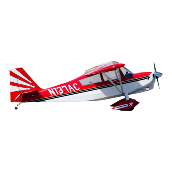
- Page 1 Super Decathlon 100cc Instruction Manual Bedienungsanleitung Manuel d’utilisation Manuale di Istruzioni...
-
Page 2: Using The Manual
NOTICE HINWEIS All instructions, warranties and other collateral documents are subject to change at the sole discretion Alle Anweisungen, Garantien und anderen zugehörigen Dokumente können im eigenen Ermessen von of Horizon Hobby, Inc. For up-to-date product literature, visit horizonhobby. com and click on the support Horizon Hobby, Inc. -
Page 3: Utilisation Du Manuel
REMARQUE AVVISO La totalité des instructions, garanties et autres documents est sujette à modifi cation à la seule discrétion Tutte le istruzioni, le garanzie e gli altri documenti pertinenti sono soggetti a cambiamenti a totale d’Horizon Hobby, Inc. Pour obtenir la documentation à jour, rendez-vous sur le site horizonhobby.com et discrezione di Horizon Hobby, Inc. -
Page 4: Safety Warnings And Precautions
SAFETY WARNINGS AND PRECAUTIONS WARNUNGEN UND SICHERHEITS- AVERTISSEMENTS RELATIFS À LA AVVERTIMENTI E PRECAUZIONI PER LA VORKEHRUNGEN. SÉCURITÉ SICUREZZA Read and follow all instructions and safety precautions before use. Improper use can result in fi re, serious injury Bitte lesen und befolgen Sie alle Anweisungen und Lisez et suivez toutes les instructions relatives à... -
Page 5: Safe Operating Recommendations
SAFE OPERATING RECOMMENDATIONS EMPFEHLUNGEN ZUM SICHEREN CONSIGNES DE SÉCURITÉ CONCERNANT RACCOMANDAZIONI PER OPERARE IN BETRIEB L’UTILISATION. SICUREZZA • Inspect your model before every fl ight to ensure it is airworthy • Überprüfen Sie zur Flugtauglichkeit ihr Modell vor • Inspectez votre modèle avant chaque vol. •... -
Page 6: Fasteners
FASTENERS • VERBINDUNGSELEMENTE • ELÉMENTS DE FIXATION • ELEMENTI DI FISSAGGIO #4 Washer Machined Aluminum Jury strut attachment (x4) 4-40 x 5/8-inch #4 Unterlegscheibe Aluminium Strebenhalter (x4) #4 Rondelle Chape de fi xation de hauban usinée en alu- 4-40 x 1-inch minium (4) #4 Rondelle Attacco struttura in alluminio (x4) -
Page 7: Assembly Symbol Guide
ASSEMBLY SYMBOL GUIDE • MONTAGE SYMBOLE • GUIDE DES SYMBOLES POUR ASSEMBLAGE • GUIDA AI SIMBOLI DI ASSEMBLAGGIO Apply threadlock Ensure free rotation Use medium CA Use a pencil Schraubensicherung- Rotation sicherstellen Mittelfl üssigen Sekun- Verwenden Sie einen slack verwenden denkleber verwenden Bleistift Permettez une rotation... -
Page 8: Table Des Matières
INDICE TABLE OF CONTENTS INHALTSVERZEICHNIS TABLE DES MATIÈRES Halterung ..............6 Eléments d’assemblage ..........6 Elementi di fissaggio ..........6 Fasteners ..............6 Symbolerklärung für den Zusammenbau ....7 Schéma de montage ..........7 Assembly Symbol Guide ..........7 Guida ai simboli di assemblaggio ......7 Spezifikationen ............9 Caractéristiques ............9 Specifiche ..............9 Specifications .............9... -
Page 9: Specifications
137.9 in (350.3 cm) 3177 sq in (204.96 sq dm) 96 in (243.9 cm) 38–42 lb (6.8–7.1 kg) 2-Stroke Gas: 100-120cc 2-Takt Benzin Motor: 100-120cc 2 temps essence : 100-120cc 2 Tempi a benzina: 100-120cc 4-channel (or greater) with 6 servos 4- Kanal (oder größer) mit 6 Servos 4 voies (ou plus) avec 6 servos 4 canali (o più) con 6 servi... -
Page 10: Required Items
REQUIRED ITEMS • ERFORDERLICHE TEILE • ELÉMENTS REQUIS • ARTICOLI NECESSARI Part English Deutsch Français Italiano SPMAR9110 AR9110 9-CH DSMX PowerSafe Receiver (1) AR9110 9-CH DSMX PowerSafe-Empfänger (1) Récepteur PowerSafe AR9110 9-voies DSMX (1) Ricevitore PowerSafe DSMX AR9110 9-CH (1) SPM9645 Remote Receiver (1) Satellitenempfänger (1) -
Page 11: Required Tools
REQUIRED TOOLS • BENÖTIGTES WERKZEUG • OUTILS REQUIS • ATTREZZI NECESSARI English Deutsch Français Italiano Rotary tool Drehbohrer Perceuse de précision Trapano Ruler Lineal Règle Righello Covering iron Folieneisen Fer à entoiler Ferro da stiro per coperture Crimping tool Crimpzange Pince à... -
Page 12: Avant De Débuter Le Montage
BEFORE STARTING ASSEMBLY VOR DEM ZUSAMMENBAU AVANT DE COMMENCER L’ASSEMBLAGE PRIMA DI INIZIARE IL MONTAGGIO • Remove parts from bag • Entnehmen Sie zur Überprüfung jedes Teil der Ver- • Retirez toutes les pièces des sachets pour les • Togliere tutti i pezzi dalla scatola. packung. -
Page 13: Landing Gear & Strut Bracket Installation
LANDING GEAR & STRUT BRACKET INSTALLATION • ZUSAMMENBAU VON FAHRWERKSTREBE UND STREBENHALTERUNG • ASSEMBLAGE DU TRAIN D’ATTERRISSAGE ET DES ENTRETOISES DES HAUBANS • ASSEMBLAGE DU TRAIN D’ATTERRISSAGE ET DES ENTRETOISES DES HAUBANS • INSTALLAZIONE DEL CARRELLO DI ATTERRAGGIO E DEI SUPPORTI DEI MONTANTI 1 2... - Page 14 LANDING GEAR & STRUT BRACKET INSTALLATION • ZUSAMMENBAU VON FAHRWERKSTREBE UND STREBENHALTERUNG • ASSEMBLAGE DU TRAIN D’ATTERRISSAGE ET DES ENTRETOISES DES HAUBANS • ASSEMBLAGE DU TRAIN D’ATTERRISSAGE ET DES ENTRETOISES DES HAUBANS • INSTALLAZIONE DEL CARRELLO DI ATTERRAGGIO E DEI SUPPORTI DEI MONTANTI 4 5...
- Page 15 LANDING GEAR & STRUT BRACKET INSTALLATION • ZUSAMMENBAU VON FAHRWERKSTREBE UND STREBENHALTERUNG • ASSEMBLAGE DU TRAIN D’ATTERRISSAGE ET DES ENTRETOISES DES HAUBANS • ASSEMBLAGE DU TRAIN D’ATTERRISSAGE ET DES ENTRETOISES DES HAUBANS • INSTALLAZIONE DEL CARRELLO DI ATTERRAGGIO E DEI SUPPORTI DEI MONTANTI 7 8...
-
Page 16: Strebenhalterung
LANDING GEAR & STRUT BRACKET INSTALLATION • ZUSAMMENBAU VON FAHRWERKSTREBE UND STREBENHALTERUNG • ASSEMBLAGE DU TRAIN D’ATTERRISSAGE ET DES ENTRETOISES DES HAUBANS • ASSEMBLAGE DU TRAIN D’ATTERRISSAGE ET DES FERRURES DES HAUBANS • INSTALLAZIONE DEL CARRELLO DI ATTERRAGGIO E DEI SUP- PORTI DEI MONTANTI 10 11... -
Page 17: Rudder Hinging And Control Horn Installation
LANDING GEAR & STRUT BRACKET INSTALLATION • ZUSAMMENBAU VON FAHRWERKSTREBE UND STREBENHAL- RUDDER HINGING AND CONTROL HORN INSTALLA- TERUNG • ASSEMBLAGE DU TRAIN D’ATTERRISSAGE ET DES FERRURES DES HAUBANS • ASSEMBLAGE DU TRAIN TION • ZUSAMMENBAU DER SEITENRUDERSCHARNI- D’ATTERRISSAGE ET DES ENTRETOISES DES HAUBANS • INSTALLAZIONE DEL CARRELLO DI ATTERRAGGIO E DEI ERE UND DES RUDERHORNS •... -
Page 18: Ruderhorns
RUDDER HINGING AND CONTROL HORN INSTALLATION • ZUSAMMENBAU DER SEITENRUDERSCHARNIERE UND DES RUDERHORNS • ASSEMBLAGE DE LA CHARNIÈRE DE LA GOUVERNE DE DIRECTION ET DU GUIGNOL DE COMMANDE • INCERNIERATURA DEL TIMONE E INSTALLAZIONE DELLA SQUADRETTA 2 3 4 Mount the control horn. Adjust the height of the control horn to 21mm from Complete the installation of the control horn on both sides following the same The bottom fuselage hinge hole is not fully open. - Page 19 RUDDER HINGING AND CONTROL HORN INSTALLATION • ZUSAMMENBAU DER SEITENRUDERSCHARNIERE UND DES RUDERHORNS • ASSEMBLAGE DE LA CHARNIÈRE DE LA GOUVERNE DE DIRECTION ET DU GUIGNOL DE COMMANDE • INCERNIERATURA DEL TIMONE E INSTALLAZIONE DELLA SQUADRETTA 5 6 7 Apply some petroleum jelly to hinge knuckle and pin only and not the shaft of Mix some 30 minute epoxy.
- Page 20 RUDDER HINGING AND CONTROL HORN INSTALLATION • ZUSAMMENBAU DER SEITENRUDERSCHARNIERE UND DES RUDERHORNS • ASSEMBLAGE DE LA CHARNIÈRE DE LA GOUVERNE DE DIRECTION ET DU GUIGNOL DE COMMANDE • INCERNIERATURA DEL TIMONE E INSTALLAZIONE DELLA SQUADRETTA 8 9 10 Apply a thin layer of epoxy to the hinge shaft. Insert the hinges in the rudder and apply a thin layer of epoxy to the other Using a mixing stick, apply epoxy to the hinge holes of the fuselage side of the hinge shaft.
- Page 21 RUDDER HINGING AND CONTROL HORN INSTALLATION • ZUSAMMENBAU DER SEITENRUDERSCHARNIERE UND DES RUDERHORNS • ASSEMBLAGE DE LA CHARNIÈRE DE LA GOUVERNE DE DIRECTION ET DU GUIGNOL DE COMMANDE • INCERNIERATURA DEL TIMONE E INSTALLAZIONE DELLA SQUADRETTA 11 12 Insert the rudder into the vertical fi n and press in for minimal hinge line gap. Clean any epoxy that oozes out with alcohol swab and using masking tape Check to make sure that full travel to each side is possible.
-
Page 22: Elevator Servos, Control Horn And Stab Installation
ELEVATOR SERVOS, CONTROL HORN AND STAB INSTALLATION • ZUSAMMENBAU DER HÖHENRUDERSERVOS, DES RUDERNHORNS UND DES STABILISATORS • ASSEMBLAGE DES SERVOS DES GOUVERNES DE PROFONDEUR, DU GUIGNOL DE COMMANDE ET DES STABILISATEURS • INSTALLAZIONE DEL SERVO DELL’ELEVATORE, DELLA SQUAD- RETTA E DELLO STABILIZZATORE 1 2 3... - Page 23 ELEVATOR SERVOS, CONTROL HORN AND STAB INSTALLATION • ZUSAMMENBAU DER HÖHENRUDERSERVOS, DES RUDERNHORNS UND DES STABILISATORS • ASSEMBLAGE DES SERVOS DES GOUVERNES DE PROFONDEUR, DU GUIGNOL DE COMMANDE ET DES STABILISATEURS • INSTALLAZIONE DEI SERVI DELL’ELEVATORE, DELLA SQUADRETTA E DELLO STABILIZZATORE 4 5 6...
- Page 24 ELEVATOR SERVOS, CONTROL HORN AND STAB INSTALLATION • ZUSAMMENBAU DER HÖHENRUDERSERVOS, DES RUDERNHORNS UND DES STABILISATORS • ASSEMBLAGE DES SERVOS DES GOUVERNES DE PROFONDEUR, DU GUIGNOL DE COMMANDE ET DES STABILISATEURS • INSTALLAZIONE DEI SERVI DELL’ELEVATORE, DELLA SQUADRETTA E DELLO STABILIZZATORE 7 8 9...
- Page 25 ELEVATOR SERVOS, CONTROL HORN AND STAB INSTALLATION • ZUSAMMENBAU DER HÖHENRUDERSERVOS, DES RUDERNHORNS UND DES STABILISATORS • ASSEMBLAGE DES SERVOS DES GOUVERNES DE PROFONDEUR, DU GUIGNOL DE COMMANDE ET DES STABILISATEURS • INSTALLAZIONE DEI SERVI DELL’ELEVATORE, DELLA SQUADRETTA E DELLO STABILIZZATORE 10 11 12...
- Page 26 ELEVATOR SERVOS, CONTROL HORN AND STAB INSTALLATION • ZUSAMMENBAU DER HÖHENRUDERSERVOS, DES RUDERNHORNS UND DES STABILISATORS • ASSEMBLAGE DES SERVOS DES GOUVERNES DE PROFONDEUR, DU GUIGNOL DE COMMANDE ET DES STABILISATEURS • INSTALLAZIONE DEI SERVI DELL’ELEVATORE, DELLA SQUADRETTA E DELLO STABILIZZATORE 13 14 15...
- Page 27 ELEVATOR SERVOS, CONTROL HORN AND STAB INSTALLATION • ZUSAMMENBAU DER HÖHENRUDERSERVOS, DES RUDERNHORNS UND DES STABILISATORS • ASSEMBLAGE DES SERVOS DES GOUVERNES DE PROFONDEUR, DU GUIGNOL DE COMMANDE ET DES STABILISATEURS • INSTALLAZIONE DEI SERVI DELL’ELEVATORE, DELLA SQUADRETTA E DELLO STABILIZZATORE 16 17 18...
- Page 28 ELEVATOR SERVOS, CONTROL HORN AND STAB INSTALLATION • ZUSAMMENBAU DER HÖHENRUDERSERVOS, DES RUDERNHORNS UND DES STABILISATORS • ASSEMBLAGE DES SERVOS DES GOUVERNES DE PROFONDEUR, DU GUIGNOL DE COMMANDE ET DES STABILISATEURS • INSTALLAZIONE DEI SERVI DELL’ELEVATORE, DELLA SQUADRETTA E DELLO STABILIZZATORE 19 20 21...
-
Page 29: Rudder Servo And Pull-Pull Cable Installation
Höhenruder in neutraler Stellung befi ndet. Die Länge der Verbindung locations. À l’aide d’une clé à molette, fi xez la tige à bout fi leté Hangar 9 au guignol de zwischen dem Ruderhorn und dem Kugelkopf sollte etwa 123 mm betragen. - Page 30 RUDDER SERVO AND PULL-PULL CABLE INSTALLATION • EINBAU VON HÖHENRUDERSERVO UND PULL-PULL-KABEL • ASSEMBLAGE DU CÂBLE « PULL-PULL » ET DU SERVO DE LA GOUVERNE DE DIRECTION • INSTALLAZIONE DEL SERVO DEL TIMONE E DEI CAVETTI DI COMANDO 2 3 4 Using a pin vise or 1/16-inch drill bit, drill the mounting locations.
- Page 31 RUDDER SERVO AND PULL-PULL CABLE INSTALLATION • EINBAU VON HÖHENRUDERSERVO UND PULL-PULL-KABEL • ASSEMBLAGE DU CÂBLE « PULL-PULL » ET DU SERVO DE LA GOUVERNE DE DIRECTION • INSTALLAZIONE DEL SERVO DEL TIMONE E DEI CAVETTI DI COMANDO 5 6 7 Secure the 48-inch extension to the rudder servo lead using a string.
- Page 32 RUDDER SERVO AND PULL-PULL CABLE INSTALLATION • EINBAU VON HÖHENRUDERSERVO UND PULL-PULL-KABEL • ASSEMBLAGE DU CÂBLE « PULL-PULL » ET DU SERVO DE LA GOUVERNE DE DIRECTION • INSTALLAZIONE DEL SERVO DEL TIMONE E DEI CAVETTI DI COMANDO 8 9 10 Screw the threaded stud into the ball link.
- Page 33 RUDDER SERVO AND PULL-PULL CABLE INSTALLATION • EINBAU VON HÖHENRUDERSERVO UND PULL-PULL-KABEL • ASSEMBLAGE DU CÂBLE « PULL-PULL » ET DU SERVO DE LA GOUVERNE DE DIRECTION • INSTALLAZIONE DEL SERVO DEL TIMONE E DEI CAVETTI DI COMANDO 11 12 13 Use a crimper and crimp the cable.
- Page 34 RUDDER SERVO AND PULL-PULL CABLE INSTALLATION • EINBAU VON HÖHENRUDERSERVO UND PULL-PULL-KABEL • ASSEMBLAGE DU CÂBLE « PULL-PULL » ET DU SERVO DE LA GOUVERNE DE DIRECTION • INSTALLAZIONE DEL SERVO DEL TIMONE E DEI CAVETTI DI COMANDO 14 15 16 Screw in both arm set screws.
- Page 35 RUDDER SERVO AND PULL-PULL CABLE INSTALLATION • EINBAU VON HÖHENRUDERSERVO UND PULL-PULL-KABEL • ASSEMBLAGE DU CÂBLE « PULL-PULL » ET DU SERVO DE LA GOUVERNE DE DIRECTION • INSTALLAZIONE DEL SERVO DEL TIMONE E DEI CAVETTI DI COMANDO 17 18 19 Criss Cross the rudder cables and pass them through the slots.
- Page 36 RUDDER SERVO AND PULL-PULL CABLE INSTALLATION • EINBAU VON HÖHENRUDERSERVO UND PULL-PULL-KABEL • ASSEMBLAGE DU CÂBLE « PULL-PULL » ET DU SERVO DE LA GOUVERNE DE DIRECTION • INSTALLAZIONE DEL SERVO DEL TIMONE E DEI CAVETTI DI COMANDO 20 21 22 Cut the excess cable.
- Page 37 RUDDER SERVO AND PULL-PULL CABLE INSTALLATION • EINBAU VON HÖHENRUDERSERVO UND PULL-PULL-KABEL • ASSEMBLAGE DU CÂBLE « PULL-PULL » ET DU SERVO DE LA GOUVERNE DE DIRECTION • INSTALLAZIONE DEL SERVO DEL TIMONE E DEI CAVETTI DI COMANDO 23 24 25 Pull the wire bundle close to the wire guide location and then push it in the The picture above shows the fi...
-
Page 38: Tail Wheel Assembly Installation
TAIL WHEEL ASSEMBLY INSTALLATION • ZUSAMMENBAU DES SPORNRADES • FIXATION ET MONTAGE DE LA ROULETTE DE QUEUE • FIXATION ET MONTAGE DE LA ROU- LETTE DE QUEUE • INSTALLAZIONE DEL GRUPPO RUOTINO DI CODA 1 2 3 Place the tiller arm over the rudder such that it is parallel with the control Run the mounting screws in and out of the holes. - Page 39 TAIL WHEEL ASSEMBLY INSTALLATION • ZUSAMMENBAU DES SPORNRADES • FIXATION ET MONTAGE DE LA ROULETTE DE QUEUE • FIXATION ET MONTAGE DE LA ROU- LETTE DE QUEUE • INSTALLAZIONE DEL GRUPPO RUOTINO DI CODA 4 5 6 Apply some thin CA in the holes and allow time for the glue to dry. Complete the tiller arm installation by tightening the wood screws.
-
Page 40: Switch And Regulator Installation
SWITCH AND REGULATOR INSTALLATION • EINBAU DES TAIL WHEEL ASSEMBLY INSTALLATION • ZUSAMMENBAU DES SPORNRADES • FIXATION ET MONTAGE DE LA SCHALTERS UND DES REGLERS • INSTALLATION DES ROULETTE DE QUEUE • FIXATION ET MONTAGE DE LA ROULETTE DE QUEUE • INSTALLAZIONE DEL GRUPPO RUO- INTERRUPTEURS ET DES RÉGULATEURS •... - Page 41 SWITCH AND REGULATOR INSTALLATION • EINBAU DES SCHALTERS UND DES REGLERS • INSTALLATION DES INTERRUPTEURS ET DES RÉGULATEURS • INSTALLAZIONE DEGLI INTERRUTTORI E DEI REGOLATORI 2 3 4 Apply masking tape to the back of the regulators. Apply a piece of double sided tape to the masking tape. Remove the rubber grommets from the regulator mounting tabs.
-
Page 42: Receiver Installation
SWITCH AND REGULATOR INSTALLATION • EINBAU DES RECEIVER INSTALLATION • EINBAU DES EMPFÄNGERS • INSTALLATION DU RÉCEPTEUR • INSTALLAZIONE DEL SCHALTERS UND DES REGLERS • INSTALLATION DES RICEVITORE INTERRUPTEURS ET DES RÉGULATEURS • INSTALLAZI- 1 2 ONE DEGLI INTERRUTTORI E DEI REGOLATORI 5 Apply masking tape to the back of the power-safe receiver. - Page 43 RECEIVER INSTALLATION • EINBAU DES EMPFÄNGERS • INSTALLATION DU RÉCEPTEUR • INSTALLAZIONE DEL RICEVITORE 3 4 5 Using medium CA and glue a piece of hook and loop to the foam. Apply medium CA to the receiver tray and glue opposite side of hook and Wait until CA is dry or use an accelerator before mounting the receiver over loop used on the receiver.
- Page 44 RECEIVER INSTALLATION • EINBAU DES EMPFÄNGERS • INSTALLATION DU RÉCEPTEUR • INSTALLAZIONE DEL RICEVITORE 6 7 8 Location of remote receiver number 1. Use a piece of double sided tape to mount the remote receivers. Location of remote receiver number 2. Befestigen Sie Satellitenempfänger mit einem Stück doppelseitigem Position des Satellitenempfänger 1.
-
Page 45: Receiver Battery Installation
RECEIVER INSTALLATION • EINBAU DES EMPFÄNGERS RECEIVER BATTERY INSTALLATION • EINBAU DES EMPFÄNGERAKKUS • INSTALLATION DES BATTERIES DU RÉ- • INSTALLATION DU RÉCEPTEU DU RÉCEPTEUR • IN- CEPTEUR • INSTALLAZIONE DELLE BATTERIE DEL RICEVITORE STALLAZIONE DEL RICEVITORE 9 1 2 Location of the remote receiver number 3 and 4. - Page 46 RECEIVER BATTERY INSTALLATION • EINBAU DES EMPFÄNGERAKKUS • INSTALLATIONDES BATTERIES DU RÉCEPTEUR • INSTALLAZIONE DELLE BATTERIE DEL RICEVITORE 3 4 5 Cut two pieces of the opposite side of hook and loop to glue to inside the Apply medium CA to the back of hook and loop. Stick the pieces to the inside side walls of the engine box between the slots engine box where the batteries are to be installed.
- Page 47 RECEIVER BATTERY INSTALLATION • EINBAU DES EMPFÄNGERAKKUS • INSTALLATION DES BATTERIES DU RÉCEPTEUR • INSTALLAZIONE DELLE BATTERIE DEL RICEVITORE 6 7 8 Cut 4 pieces of 4-inch long large fuel line. Mount the batteries. Pass the tie wrap from the slot on the outside of the engine box to inside. Führen Sie den Kabelbinder durch den Schlitz in den Motorraum, wie in dem Schneiden Sie vier Stücke 4 Zoll lange, weite Kraftstoffl...
- Page 48 RECEIVER BATTERY INSTALLATION • EINBAU DES EMPFÄNGERAKKUS • INSTALLATION DES BATTERIES DU RÉCEPTEUR • INSTALLAZIONE DELLE BATTERIE DEL RICEVITORE 9 10 11 Grab the tie wrap from inside and pass the fuel line through it. Tighten the tie wraps from outside of the engine box and cut the excess. For safety purpose, double up the tie wraps on each battery as in the picture above.
-
Page 49: Ignition Module, Battery And Switch Installation
IGNITION MODULE, BATTERY AND SWITCH INSTALLATION • EINBAU VON ZÜNDMODUL, AKKU UND SCHALTER • INSTALLATION DU MODULE D’ALLUMAGE, DES BATTERIES ET DE L’INTERRUPTEUR CORRESPONDANT • INSTALLAZIONE DEL MODULO DI ACCENSIONE, DELLA BATTERIA E DELL’INTERRUTTORE 1 2 3 Apply masking tape to the back of ignition module. Cut a piece of 1/4-inch foam and using medium CA, glue to the masking tape. - Page 50 IGNITION MODULE, BATTERY AND SWITCH INSTALLATION • EINBAU VON ZÜNDMODUL, AKKU UND SCHALTER • INSTALLATION DU MODULE D’ALLUMAGE, DES BATTERIES ET DE L’INTERRUPTEUR CORRESPONDANT • INSTALLAZIONE DEL MODULO DI ACCENSIONE, DELLA BATTERIA E DELL’INTERRUTTORE 4 5 6 The ignition module and ignition battery are to be installed back to back with Use a tie wrap and 2 pieces of fuel lines to complete the installation.
-
Page 51: Engine And Throttle Servo Installation
IGNITION MODULE, BATTERY AND SWITCH INSTALLA- ENGINE AND THROTTLE SERVO INSTALLATION • EINBAU DES SERVOS FÜR MOTOR UND GASGEBER • INSTALLA- TION • EINBAU VON ZÜNDMODUL, AKKU UND SCHAL- TION DU MOTEUR ET DU SERVO DE COMMANDE DES GAZ • INSTALLAZIONE DEL MOTORE E DEL SUO SERVO TER •... - Page 52 ENGINE AND THROTTLE SERVO INSTALLATION • EINBAU DES SERVOS FÜR MOTOR UND GASGEBER • INSTALLATION DU MOTEUR ET DU SERVO DE COMMANDE DES GAZ • INSTALLAZIONE DEL MOTORE E DEL SUO SERVO 3 4 5 Apply thread lock to the bolts. Mount the engine using 3/16-inch hex wrench.
- Page 53 ENGINE AND THROTTLE SERVO INSTALLATION • EINBAU DES SERVOS FÜR MOTOR UND GASGEBER • INSTALLATION DU MOTEUR ET DU SERVO DE COMMANDE DES GAZ • INSTALLAZIONE DEL MOTORE E DEL SUO SERVO 6 7 8 Remove the servo. Using a pin vise or 1/16-inch drill bit, drill the servo mount- Insert the screws in the holes and back them out.
- Page 54 ENGINE AND THROTTLE SERVO INSTALLATION • EINBAU DES SERVOS FÜR MOTOR UND GASGEBER • INSTALLATION DU MOTEUR ET DU SERVO DE COMMANDE DES GAZ • INSTALLAZIONE DEL MOTORE E DEL SUO SERVO 9 10 11 Once CA is dry, install the servo. Thread the nylon clevis onto the end of the threaded push rod.
- Page 55 ENGINE AND THROTTLE SERVO INSTALLATION • EINBAU DES SERVOS FÜR MOTOR UND GASGEBER • INSTALLATION DU MOTEUR ET DU SERVO DE COMMANDE DES GAZ • INSTALLAZIONE DEL MOTORE E DEL SUO SERVO 12 13 14 Mark the throttle rod where it needs to be mounted on the arm. It’s recom- Cut the excess rod 10mm past the marked location.
- Page 56 ENGINE AND THROTTLE SERVO INSTALLATION • EINBAU DES SERVOS FÜR MOTOR UND GASGEBER • INSTALLATION DU MOTEUR ET DU SERVO DE COMMANDE DES GAZ • INSTALLAZIONE DEL MOTORE E DEL SUO SERVO 15 16 17 Connect the Z-bent side of the rod to the servo arm. Measure about 1 3/4- Slightly bend the rod to avoid touching the engine box when installed.
-
Page 57: Fuel Tank Installation And Plumbing
FUEL TANK INSTALLATION AND PLUMBING • ZUSAM- ENGINE AND THROTTLE SERVO INSTALLATION • EINBAU DES SERVOS FÜR MOTOR UND GASGEBER • INSTALLA- MENBAU VON BENZINTANK UND LEITUNGEN • INSTAL- TION DU MOTEUR ET DU SERVO DE COMMANDE DES GAZ • INSTALLAZIONE DEL MOTORE E DEL SUO SERVO LATION DU RÉSERVOIR ET DES DURITES POUR LE 18 19... - Page 58 FUEL TANK INSTALLATION AND PLUMBING • ZUSAMMENBAU VON BENZINTANK UND LEITUNGEN • INSTALLATION DU RÉSERVOIR ET DES DURITES POUR LE CARBURANT • INSTALLAZIONE SERBATOIO E TUBETTI CARBURANTE 2 3 4 Apply two pieces of double sided tape to the bottom of the tank. To make the tie wrap installation easier, loop the tie wraps through the slots Peel off the double sided tape cover for fi...
-
Page 59: Cowl Preparation And Muffler Installation
FUEL TANK INSTALLATION AND PLUMBING • ZUSAMMENBAU VON BENZINTANK UND LEITUNGEN • INSTALLATION COWL PREPARATION AND MUFFLER INSTALLATION • DU RÉSERVOIR ET DES DURITES POUR LE CARBURANT • INSTALLAZIONE SERBATOIO E TUBETTI CARBURANTE VORBEREITUNG DER VERKLEIDUNG UND EINBAU DES SCHALLDÄMPFERS • PRÉPARATION DU CAPOT ET IN- STALLATION DES SILENCIEUX •... - Page 60 COWL PREPARATION AND MUFFLER INSTALLATION • VORBEREITUNG DER VERKLEIDUNG UND EINBAU DES SCHALLDÄMPFERS • PRÉPARATION DU CAPOT ET INSTALLATION DES SILENCIEUX • PREPARAZIONE DELLA CARENATURA E INSTALLAZIONE DEL SILENZIATORE 2 3 4 4 1/4-inch 2 3/4-inch Once it’s open smooth out the edges using a sanding drum. Mark the depicted area using a felt-tip pen.
- Page 61 COWL PREPARATION AND MUFFLER INSTALLATION • VORBEREITUNG DER VERKLEIDUNG UND EINBAU DES SCHALLDÄMPFERS • PRÉPARATION DU CAPOT ET INSTALLATION DES SILENCIEUX • PREPARAZIONE DELLA CARENATURA E INSTALLAZIONE DEL SILENZIATORE 5 6 7 To cut out the muffl er opening in the cowl, temporary install one muffl er at Using a rotary tool and a sander, open up the landing light hole for the front Apply thread lock to muffl...
- Page 62 COWL PREPARATION AND MUFFLER INSTALLATION • VORBEREITUNG DER VERKLEIDUNG UND EINBAU DES SCHALLDÄMPFERS • PRÉPARATION DU CAPOT ET INSTALLATION DES SILENCIEUX • PREPARAZIONE DELLA CARENATURA E INSTALLAZIONE DEL SILENZIATORE 8 9 10 The picture above shows how the ignition wire is routed to the spark plugs. Install the cowl using 4-40 x 1/2-inch screws and cone washers provided.
-
Page 63: Wing Servo Installation And Aileron Hinging
COWL PREPARATION AND MUFFLER INSTALLATION • VORBEREITUNG DER VERKLEIDUNG UND EINBAU DES WING SERVO INSTALLATION AND AILERON HINGING • SCHALLDÄMPFERS • PRÉPARATION DU CAPOT ET INSTALLATION DES SILENCIEUX • PREPARAZIONE DELLA EINBAU DES FLÜGELSERVOS UND DER QUERRUDER- CARENATURA E INSTALLAZIONE DEL SILENZIATORE SCHARNIERE •... - Page 64 WING SERVO INSTALLATION AND AILERON HINGING • EINBAU DES FLÜGELSERVOS UND DER QUERRUDERSCHARNIERE • INSTALLATION DES SERVOS ET DES CHARNIÈRES DES AILERONS • INSTALLAZIONE SERVI NELL’ALA E CERNIERE ALETTONI 2 3 4 Insert the servo screws in and out of the holes. Apply some thin CA in the holes to harden the threads.
- Page 65 WING SERVO INSTALLATION AND AILERON HINGING • EINBAU DES FLÜGELSERVOS UND DER QUERRUDERSCHARNIERE • INSTALLATION DES SERVOS ET DES CHARNIÈRES DES AILERONS • INSTALLAZIONE SERVI NELL’ALA E CERNIERE ALETTONI 5 6 7 The picture above shows the right and left aileron servos installed in the Connect a 36-inch JR Heavy-Duty extension to the servo lead.
- Page 66 Serrez ensuite les vis se trouvant sur les côtés. slack auf die mittlere Schraube des Servos und montieren Sie die Schraube. Vissez la tige à bout fi leté Hangar 9 au guignol de commande et à la chape à Quindi serrare le viti laterali.
- Page 67 WING SERVO INSTALLATION AND AILERON HINGING • EINBAU DES FLÜGELSERVOS UND DER QUERRUDERSCHARNIERE • INSTALLATION DES SERVOS ET DES CHARNIÈRES DES AILERONS • INSTALLAZIONE SERVI NELL’ALA E CERNIERE ALETTONI 11 12 13 Adjust so that the exposed length of the pro-link rod between the ball link and Mate the ailerons to the wings, being sure to align the hinge tabs into the Carefully insert the hinge rod into the opening in the wing tip and pass it ailerons properly.
- Page 68 WING SERVO INSTALLATION AND AILERON HINGING • EINBAU DES FLÜGELSERVOS UND DER QUERRUDERSCHARNIERE • INSTALLATION DES SERVOS ET DES CHARNIÈRES DES AILERONS • INSTALLAZIONE SERVI NELL’ALA E CERNIERE ALETTONI 14 15 16 Use a fl at screwdriver to push the hinge rod into the wing tip and then tighten There is a string inside the wing to help with routing the aileron servo exten- Slowly pull the servo extension out by pulling the string at the root.
- Page 69 WING SERVO INSTALLATION AND AILERON HINGING • EINBAU DES FLÜGELSERVOS UND DER QUERRUDERSCHARNIERE • INSTALLATION DES SERVOS ET DES CHARNIÈRES DES AILERONS • INSTALLAZIONE SERVI NELL’ALA E CERNIERE ALETTONI 17 18 19 Run the servo screws through the hatch mounting locations. Apply some thin CA in the hole to harden the threads.
- Page 70 WING SERVO INSTALLATION AND AILERON HINGING • EINBAU DES FLÜGELSERVOS UND DER QUERRUDERSCHAR- WING STRUTS INSTALLATION • EINBAU DER FLÜGEL- NIERE • INSTALLATION DES SERVOS ET DES CHARNIÈRES DES AILERONS • INSTALLAZIONE SERVI NELL’ALA E STREBEN • ASSEMBLAGE DES HAUBANS DES AILES • CERNIERE ALETTONI INSTALLAZIONE DEI MONTANTI DELLE ALI 20...
-
Page 71: Wing Struts Installation
WING STRUTS INSTALLATION • EINBAU DER FLÜGELSTREBEN • ASSEMBLAGE DES HAUBANS DES AILES • INSTALLAZIONE DEI MONTANTI DELLE ALI 2 3 4 Screw in the jury strut anchor until its fl ush with the wing skin. If facing Thread on a nut and machined aluminum strut end onto the threaded end of Using a 3/32-inch ball driver to complete the installation of the strut brackets resistance, pass a screw driver through the anchor and use it as handle for both the wide and narrow struts. - Page 72 WING STRUTS INSTALLATION • EINBAU DER FLÜGELSTREBEN • ASSEMBLAGE DES HAUBANS DES AILES • INSTALLAZIONE DEI MONTANTI DELLE ALI 5 6 7 The struts are airfoild. The trailing edge of struts face the trailing edge of There are three parts that complete the connection of the fwd and rear struts Using 3/32-inch ball driver and 1/4-inch wrench, connect the shortest jury strut the wing.
- Page 73 WING STRUTS INSTALLATION • EINBAU DER FLÜGELSTREBEN • ASSEMBLAGE DES HAUBANS DES AILES • INSTALLAZIONE DEI MONTANTI DELLE ALI 8 9 10 Insert the rubber tube over the pin. Install wing and tighten in place using the 1/4-20 x 1 1/2-inch nylon thumb Install the jury struts and insert the cotter pins.
- Page 74 WING STRUTS INSTALLATION • EINBAU DER FLÜGELSTREBEN • ASSEMBLAGE DES HAUBANS DES AILES • INSTALLAZIONE DEI MONTANTI DELLE ALI 11 12 13 Adjust the aluminum strut ends to proper length and tighten nuts using a pair Insert the pin and rubber tube thru the strut and the bracket. Install the cotter The struts fold over the wing for storage and transport.
-
Page 75: Stab Flying Wire Installation
STAB FLYING WIRE INSTALLATION • VERKABELUNG UND BEFESTIGUNG DES HÖHENLEITWERKS • FIXATION DES HAUBANS DU STABILISATEUR (PLAN HORIZONTAL FIXE) • INSTALLAZIONE MONTANTI STABILIZZATORI 1 2 3 Using two pliers or a vise grip and a plier, slightly bend the aluminum brack- Pass the 4-40 x 1 1/4-inch bolt through the plate on top of the stab, then Same steps apply to the vertical fi... - Page 76 STAB FLYING WIRE INSTALLATION • VERKABELUNG UND BEFESTIGUNG DES HÖHENLEITWERKS • FIXATION DES HAUBANS DU STABILISATEUR (PLAN HORIZONTAL FIXE) • INSTALLAZIONE MONTANTI STABILIZZATORI 4 5 6 Screw the nut onto the rod and then thread on the clevis. Length of the rod for the upper stab to vertical fi n is approximately 16 5/8- Install the rod by connecting the clevises to the stab and vertical fi...
- Page 77 STAB FLYING WIRE INSTALLATION • VERKABELUNG UND BEFESTIGUNG DES HÖHENLEITWERKS • FIXATION DES HAUBANS DU STABILISATEUR (PLAN HORIZONTAL FIXE) • INSTALLAZIONE MONTANTI STABILIZZATORI 7 8 9 Install the aluminum plate to the bottom of the fuselage. The length of the rod for connection between bottom of the stab to the fuse- Connect the rod to the bottom of the stab and the bottom of fuselage.
-
Page 78: Dash And Instrument Panel Installation
DASH AND INSTRUMENT PANEL INSTALLATION • EINBAU VON ARMATURENBRETT UND INSTRUMENTENTAFEL • STAB FLYING WIRE INSTALLATION • VERKABELUNG ASSEMBLAGE DU TABLEAU DE BORD • INSTALLAZIONE DEL CRUSCOTTO E DEL PANNELLO STRUMENTI UND BEFESTIGUNG DES HÖHENLEITWERKS • FIXATION DES HAUBANS DU STABILISATEUR (PLAN HORIZONTAL 1 2 FIXE) •... - Page 79 DASH AND INSTRUMENT PANEL INSTALLATION • EINBAU VON ARMATURENBRETT UND INSTRUMENTENTAFEL • ASSEMBLAGE DU TABLEAU DE BORD • INSTALLAZIONE DEL CRUSCOTTO E DEL PANNELLO STRUMENTI 3 4 5 Apply goop or silicone glue to all the internal edge of the dash. Install the dash.
-
Page 80: Windows And Windshield Installation
DASH AND INSTRUMENT PANEL INSTALLATION • EINBAU VON ARMATURENBRETT UND INSTRUMENTENTAFEL • WINDOWS AND WINDSHIELD INSTALLATION • EIN- ASSEMBLAGE DU TABLEAU DE BORD • INSTALLAZIONE DEL CRUSCOTTO E DEL PANNELLO STRUMENTI BAU DER FENSTER UND DER WINDSCHUTZSCHEIBE • 6 7 ASINSTALLATION DES VITRAGES ET DU PARE-BRISE •... - Page 81 WINDOWS AND WINDSHIELD INSTALLATION • EINBAU DER FENSTER UND DER WINDSCHUTZSCHEIBE • INSTALLATION DES VITRAGES ET DU PARE-BRISE • INSTALLAZIONE DEI FINESTRINI E DEL PARABREZZA 2 3 4 Clean excess glue that oozes out with alcohol swabs. Hold in place with Using same method glue the rest of the windows and windshield in place.
-
Page 82: Seat Assembly And Installation
SEAT ASSEMBLY AND INSTALLATION • ZUSAMMEN- UND EINBAU DER SITZE • MONTAGE ET MISE EN PLACE DES SIÈGES • ASSEMBLAGGIO E INSTALLAZIONE DEI SEDILI 1 2 3 Rear Front Apply goop or silicone glue to the seats and glue them together. Using masking tape, hold them together until glue is cured. -
Page 83: Wing Tip Bezel And Decal Installation
WING TIP BEZEL AND DECAL INSTALLATION • EINBAU DER TRAGFLÄCHENUMRANDUNG UND ANBRINGEN DER PREFLIGHT DOOR INSTALLATION • EINBAU DER TÜR AUFKLEBER • MISE EN PLACE DES DÉCORS ET AUTOCOLLANTS ORNANT LE BOUT DES AILES ET LE FUSELAGE • VOR DEM FLUG • ASSEMBLAGE DE LA PORTE D’ACCÈS INSTALLAZIONE SMUSSO ESTREMITÀ... -
Page 84: Centro Di Gravità
CENTER OF GRAVITY DER SCHWERPUNKT CENTRE DE GRAVITÉ CENTRO DI GRAVITA’ (BARICENTRO) An important part of preparing the aircraft for fl ight is Ein wichtiger Schritt zur Vorbereitung des Flugzeugs für Une des opérations essentielles quant à la préparation Una parte importante nella preparazione di un aereo per il properly balancing the model. -
Page 85: Courses Des Commandes
CONTROL THROWS RUDERAUSSCHLÄGE DÉBATTEMENTS CORSE DEI COMANDI 1. Turn on the transmitter and receiver of your model. 1. Schalten Sie den Sender und Empfänger ihres 1. Mettez l’émetteur et le récepteur sous tension. Con- 1. Accendere trasmettitore e ricevitore del modello. Con- Check the movement of the rudder using the transmit- Modells ein. -
Page 86: Preflight Checklist
PREFLIGHT CHECKLIST VORFLUGKONTROLLE CHECKLIST D’AVANT VOL CONTROLLI PRIMA DEL VOLO • Charge the transmitter, receiver and motor battery • Laden Sie den Sender- ,Empfänger- und Zündakku • Chargez la batterie de votre émetteur, de réception et • Caricare le batterie di trasmettitore, ricevitore e ac- for your airplane. -
Page 87: Contrôles Des Vols Quotidiens
DAILY FLIGHT CHECKS TÄGLICHER FLUG CHECK CONTRÔLES SYSTÉMATIQUES CONTROLLI PER OGNI SESSIONE DI VOLI • Check the battery voltage of the transmitter battery. • Überprüfen Sie die Spannung des Senderakkus. Flie- • Contrôlez la tension de la batterie de l’émetteur. •... -
Page 88: Conditions Habituelles De Vol
Ce modèle est capable grado di eseguire tutte la manovre basiche di acrobazia ® We hope you enjoy your Hangar 9 Super Decathlon as Turns, Rückenfl ug etc.. fl iegen. d’effectuer des manoeuvre de voltige basiques ; boucles, come looping, tonneau, stalli d’ala, volo rovescio, ecc. -
Page 89: Limited Warranty
LIMITED WARRANTY GARANTIE UND SERVICE INFORMATIONEN What this Warranty Covers assistance. For questions or assistance, please visit our website Warnung akzeptieren, werden Sie gebeten, dass Produkt in unbenutztem at www.horizonhobby.com, submit a Product Support Inquiry, Ein ferngesteuertes Modell ist kein Spielzeug. Es kann, wenn Zustand in der Originalverpackung vollständig bei dem Verkäufer Horizon Hobby, Inc. -
Page 90: Durata Della Garanzia
GARANTIE ET RÉPARATIONS DURATA DELLA GARANZIA Durée de la garantie quelques aptitudes mécaniques ainsi que mentales. L’incapacité Periodo di garanzia Indicazioni di sicurezza à utiliser le produit de manière sûre et raisonnable peut Garantie exclusive - Horizon Hobby, Inc. (Horizon) garantit que le Garanzia esclusiva - Horizon Hobby, Inc., (Horizon) garantisce Questo è... -
Page 91: Coordonnées Des Services Pour La Garantie Et La Réparation
WARRANTY AND SERVICE CONTACT INFORMATION • GARANTIE UND SERVICE KONTAKTIN- WARRANTY AND SERVICE CONTACT INFORMATION • KUNDENDIENSTINFORMATIONEN • FORMATIONEN • COORDONNÉES DE GARANTIE ET RÉPARATIONS • GARANZIA E ASSISTEN- INFORMATIONS DE CONTACT POUR LES PIÈCES • INFORMAZIONI PER IL SERVIZIO CLIENTI ZA INFORMAZIONI PER I CONTATTI 877-504-0233 4105 Fieldstone Rd... - Page 92 mended Field Layout): FAA INFORMATION FOR HORIZON MANUALS AMA NATIONAL MODEL AIRCRAFT SAFETY CODE (i) Not operate model aircraft carrying pyrotechnic devices (a) Only personnel associated with fl ying the model aircraft Prior to fl ying, contact your local or regional modeling organiza- Effective January 1, 2011 which explode or burn, or any device which propels a projec- are allowed at or in front of the safety line.
- Page 94 © 2012 Horizon Hobby, Inc. Hangar 9, Evolution, JR, DSM2, Side Force Generators, PowerPro and the Horizon Hobby logo are trademarks or registered trademarks of Horizon Hobby, Inc. DSMX is a trademark of Horizon Hobby, Inc. registered in the U.S.