
Manuels Connexes pour Hangar 9 Messerschmitt Bf 109F-2 60


Sommaire des Matières pour Hangar 9 Messerschmitt Bf 109F-2 60
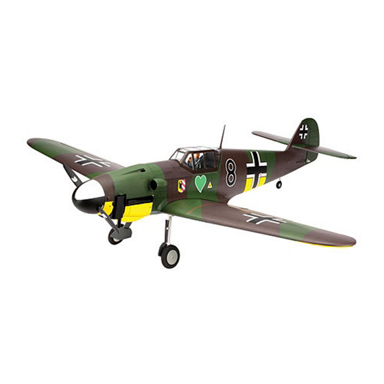
- Page 1 Instruction Manual Messerschmitt Bf 109F-2 60 Bedienungsanleitung Manuel d’utilisation Manuale di Istruzioni...
-
Page 2: Using The Manual
NOTICE HINWEIS All instructions, warranties and other collateral documents are subject to change at the sole discretion of Alle Anweisungen, Garantien und anderen zugehörigen Dokumente können im eigenen Ermessen von Horizon Horizon Hobby, Inc. For up-to-date product literature, visit horizonhobby. com and click on the support tab for Hobby, Inc. -
Page 3: Utilisation Du Manuel
REMARQUE AVVISO La totalité des instructions, garanties et autres documents est sujette à modification à la seule discrétion Tutte le istruzioni, le garanzie e gli altri documenti pertinenti sono soggetti a cambiamenti a totale discrezione d’Horizon Hobby, Inc. Pour obtenir la documentation à jour, rendez-vous sur le site horizonhobby.com et cliquez di Horizon Hobby, Inc. -
Page 4: Safety Warnings And Precautions
safety warnings and preCaUtions warnUngen Und siCherheits- avertisseMents relatifs à la avvertiMenti e preCaUZioni per la vorkehrUngen séCUrité siCUreZZa Read and follow all instructions and safety precautions before use. Improper use can result in fire, serious injury and Bitte lesen und befolgen Sie alle Anweisungen und Lisez et suivez toutes les instructions relatives à... -
Page 5: Safe Operating Recommendations
safe operating reCoMMendations eMpfehlUngen ZUM siCheren Consignes de séCUrité ConCernant raCCoMandaZioni per operare in betrieb l’Utilisation siCUreZZa • Inspect your model before every flight to ensure it is airworthy. • Überprüfen Sie zur Flugtauglichkeit ihr Modell vor jedem • Inspectez votre modèle avant chaque vol. • Controllare attentamente il modello prima di ogni volo per Flug. - Page 6 speciFications•speziFikationen• large parts layout•bauteile (ohne kleinteile)• spéciFications•speciFiche grandes pièces•schema dei componenti grandi 64.0 in (163cm) 679 sq in (43.8 dm 59.0 in (150cm) 10.25–11.5 lb (4.6–5.2 kg) 2-Stroke Glow .60–.90 2-Takt Glühzünder .60–.90 2 temps méthanol .60–.90 2-Tempi Glow .60–.90 4-Stroke Glow 1.00–1.25 4-Takt Glühzünder 1.00–1.25 4 temps méthanol 1.00–1.25...
- Page 7 replacement parts•ersatzteile•pièces de rechange•ricambi part english deutsch français italiano HAN278501 Fuselage with Hatch Rumpf mit Haube Fuselage avec capot Fusoliera con portello HAN278502 Left Wing Tragfläche links mit Querruder und Klappe Aile gauche Ala sinistra HAN278503 Right Wing Tragfläche rechts mit Querruder und Klappe Aile droite Ala destra HAN278504...
- Page 8 assembly symbol guide•montage symbole•guide des symboles pour assemblage•guida ai simboli di assemblaggio Apply threadlock Ensure free rotation Use medium CA Use a pencil Schraubensicherungslack verwenden Rotation sicherstellen Mittelflüssigen Verwenden Sie einen Bleistift Sekundenkleber verwenden Utilisez du frein filet Permettez une rotation libre Utilisez un crayon à...
- Page 9 Prolunga da 8 mm per silenziatore EVO/OS 61 HAN116 Fuel Dot Filler with “T” Coupler Hangar 9 Tanknippel mit T Stück u. Überlauf Fitting Point de remplissage de carburant avec coupleur en T Bocchettone di riempimento carburante con giunto a “T”...
- Page 10 electric power•elektroantrieb•moteur electrique (ep)•motore elettrico english deutsch français italiano EFLM4060A Power 60 Brushless Outrunner Motor, 400Kv Power 60 Brushless Outrunner-Motor, 400-Kv Moteur électrique Brushless à Motore outrunner senza spazzole Power 60, 400 Kv cage-tournante 60, 400 Kv EFLA1080B 80-Amp Pro Switch-Mode BEC Brushless ESC 80-A-Amp Pro Switch-Mode BEC Brushless Regler ESC Brushless 80 Amp Pro avec Switch-Mode BEC Regolatore di velocità...
- Page 11 english deutsch français italiano Felt-tipped pen Faserstift Feutre fin effaçable Pennarello Flat file Flachfeile Lime plate Lima piatta Hemostat Klemme Pince Hemostat Pinzetta Hex wrench: 2mm, 1.5mm, 9/64-inch, 3/32-inch, 2.5mm, 4mm Inbusschlüssel: 2mm, 1.5mm, 9/64-inch, 3/32-inch, 2.5mm, Tournevis hexagonal: 2mm, 1.5mm, 9/64-inch, 3/32-inch, Chiave esag.: 2mm, 1.5mm, 9/64-inch, 3/32-inch, 2.5mm, 2,5mm, 4mm Hobby knife: #11 blade...
-
Page 12: Before Starting Assembly
before starting asseMbly vor deM ZUsaMMenbaU avant de CoMMenCer l’asseMblage priMa di iniZiare il Montaggio • Remove parts from bag. • Entnehmen Sie zur Überprüfung jedes Teil der Verpackung. • Retirez toutes les pièces des sachets pour les inspecter. • Togliere tutti i pezzi dalla scatola. • Inspect fuselage, wing panels, rudder and stabilizer for • Überprüfen Sie den Rumpf, Tragflächen, Seiten- und • Inspectez soigneusement le fuselage, les ailes et les... - Page 13 aileron and Flap hinging•montage der klappen und querruder•pose des charnières de l’aileron et du Volet•cerniere Flap e alettoni 1 2 3 4 Apply a small amount of oil to the flex point of the hinge to Fit the hinges to the outer flap.
- Page 14 5 6 7 8 Fit the flap to the wing and check the alignment. Use a paper Remove the inner flap from the flap mount. Note the position towel and isopropyl alcohol to remove any excess epoxy before of the hinges when they are removed as they are trimmed to fit the epoxy fully cures.
- Page 15 9 10 11 12 Fit the aileron to the wing. Make sure the gap at each end of the aileron is equal so the aileron can move freely. Use a pin vise and 1/16-inch (1.5mm) drill bit to drill a hole Remove the ailerons from the wing panel.
- Page 16 13 aileron serVo installation•einbau der querruderserVos• installation des serVos d’ailerons•installazione serVo dell’alettone 1 2 3 Use a pin vise and a 1/16-inch (1.5mm) drill bit to drill the holes for the servo mounting screws through the backing plate of the servo mount.
- Page 17 4 6 7 8 Remove the covering from the opening for the servo horn in Secure a 12-inch (305mm) extension to the servo lead using Tie the string located inside the wing to the end of the 12-inch Remove the flap servo cover.
- Page 18 9 10 11 12 M2 x 10 Place the aileron cover into position. Use a pin vise and 1/16-inch (1.5mm) drill bit to drill the holes in the servo cover mounts. Remove the aileron cover from the wing. Use a T-pin to Thread a screw into each of the holes in the aileron servo Apply a small amount of thin CA to harden the threads made puncture the covering to locate the holes for the aileron cover...
- Page 19 13 14 15 16 M2 x 10 Secure the servo cover to the wing using four M1.5 x 10 self- Place a ruler along-side the servo horn. With the ruler Position the control horn at the mark made in the previous Use a pin vise and 1/16-inch (1.5mm) drill bit to drill the tapping screws.
- Page 20 17 18 19 20 M2 x 10 M2 x 10 Thread an M2 x 10 self-tapping screw into each hole to cut Apply a small amount of thin CA to harden the threads made Secure the control horn to the aileron. Cut a 1/4-inch (6mm) piece of silicone tubing as shown.
- Page 21 21 22 outer Flap serVo installation•einbau der äusseren klappenserVos•installation du serVo du Volet extérieur• installaZione del servo del flap esterno 1 2 Thread the clevis on a pre-bent 45mm aileron rod. This Insert the Z-bend in the hole that is 17/32 inch (13.5mm) pushrod has a Z-bend in the end as shown.
- Page 22 3 4 5 Center the flap servo using the radio system. Attach the servo horn perpendicular to the servo center line. Remove any arms that Place the flap servo into position in the wing. Guide the may interfere with the operation of the servo. Secure the servo to the cover using the screws provided with the servo. linkage through the opening at the trailing edge.
- Page 23 6 7 8 9 M2 x 10 Prepare the wing for the installation of the flap servo cover, Once the outer flap servo has been installed, carefully pull the following the steps outlined for the installation of the aileron leads for the ailerons and flap to the center of the wing.
- Page 24 10 Fixed inner Flap installation•montage der Festen inneren klappen• installation du Volet intérieur Fixe•installazione del Flap interno Fisso 1 2 Î At this time you must decide if the inner flaps will be operational. The fixed flaps are secured using silicone adhesive, which can be removed using a hobby knife and #11 blade if operational flaps are to be installed at a later date.
- Page 25 3 4 5 6 M2 x 10 M3 x 20 Secure the servo cover to the wing using four M2 x 10 self- Secure the inner flap mount to the wing. tapping screws. Use a hobby knife to remove the covering from Schrauben Sie den inneren Klappenhalter an die Tragfläche.
- Page 26 operational inner Flap installation•einbau der betriebsFähigen klappen• installation du Volet intérieur opérationnel•installazione del Flap interno operatiVo 1 2 3 4 Remove the inner flap cover from the wing. Use a small amount of clear tape to secure the aileron and flap servo leads in position so they do not move around excessively inside the Thread the clevis on a 155mm threaded rod.
- Page 27 5 6 7 Center the flap servo using the radio system. Attach the servo horn perpendicular to the servo center line. Remove any arms that Attach the pushrod to the inner hole on the flap servo. Note the Fit the inner flap servo into position.
- Page 28 8 9 10 M2 x 10 M3 x 20 Fit the inner flap into position. Attach the linkage to the flap Set the flap servo cover into position. Prepare the holes for the Fit the inner flap mount in position, attaching it with two screws at this time. Position the cover so the flap can move without control horn.
- Page 29 11 Fixed landing gear•Fixes Fahrwerk•train d’atterrissage Fixe•carrello di atterraggio Fisso 1 2 3 Use a flat file to make two 5mm wide flat areas on the landing Secure the wheel collar to the axle. Tighten the setscrew on the Apply a drop of light machine oil on the axle so the wheel can gear axle.
- Page 30 4 6 7 8 M3 x 20 Slide the wheel on the axle, then secure it using the wheel Secure the landing gear assembly in the wing. Note the Draw a center line on the inside of the landing gear door. Draw Position the gear door strap, marking the locations for the collar.
- Page 31 9 10 optional retractable landing gear•optionales einziehFahrwerk• train d’atterrissage rétractable optionnel• Carrello di atterraggio retrattile opZionale 1 2 M3 x 10 Use a pin vise and 1/8-inch (3mm) drill bit to drill the two Attach the gear door to the landing gear strut using the gear holes for the gear door strap.
- Page 32 3 4 5 6 Slide a spacer on the axle from the back of the wheel. Position the door mounting from the end of the strut as shown. With the axle fit to the retract, mark the axle so it can be Remove the axle and cut it at the mark made in the previous The upper bracket is 59mm to the top edge, the lower is trimmed.
- Page 33 7 8 9 10 Fit the axle through the wheel and secure the axle to the Trim the covering 1/8-inch (3mm) inside the opening for the Secure the retract into the wing using the hardware provided retract.
- Page 34 11 12 13 14 Position the gear door on the wing. Use the tape as a guide With the gear door removed, draw lines on the inside of the Use a pin vise and 1/8-inch (3mm) drill bit to drill the holes Attach the landing gear door to the retract using the hardware and mark the outer edges to aid in locating the screws holes cover to locate the positions of the gear door mounts.
- Page 35 receiVer and serVo installation•empFänger und serVoeinbau•installation du récepteur et du serVo•installazione del riceVitore e del serVo 1 2 3 4 Slide the canopy hatch forward then up to release, then aft to Use a pin vise and a 1/16-inch (1.5mm) drill bit to drill the Thread a servo mounting screw into each hole to cut threads remove it from the fuselage.
- Page 36 5 6 7 8 Install the grommets and brass eyelets in the servos. Secure Mount the switch harness in the fuselage. Two sizes have been Secure the receiver battery in the fuselage using a hook and Connect the leads and extensions to the receiver.
- Page 37 10 wing installation•montage der tragFlächen•installation de l’aile•montaggio dell’ala 1 2 3 Secure the remote receiver inside the fuselage using hook and loop tape. Slide the wing tube into the wing tube socket. Befestigen Sie den Satellitenempfänger mit Klettband im Schieben Sie den Flächenverbinder in die Öffnung an der Rumpf.
- Page 38 5 6 7 8 M5 x 25 Slide the wing panels together. Connect the leads from the receiver to the leads from the wing. Schieben Sie die Tragflächenhälften zusammen. Use the wing bolt to draw the blind nut into the wing Verbinden Sie die Servokabel vom Empfänger mit den Faire glisser les panneaux d’aile ensemble.
- Page 39 stabilizer installation•einbau des höhenleitwerks•installation du stabilisateur•installazione dello stabilizzatore 1 2 3 4 Slide the stabilizer tubes in the stabilizer. Schieben Sie die Höhenleitwerksverbinder in das Remove the stabilizers from the fuselage. Remove the Slide the tubes back into the stabilizer. Apply a thin coat of Höhenleitwerk.
- Page 40 5 eleVator installation•montage des höhenruders•installation de la proFondeur•installazione dell’eleVatore 1 2 Remove the elevators and hinges from the stabilizer. Use a pin vise and 1/16-inch (1.5mm) drill bit to drill a hole in the center of Fit the elevator into position, checking that the joiner wire each hinge slot in both the elevators and stabilizers.
- Page 41 3 4 5 Remove the elevator and hinges from the stabilizer. Lightly Wrap a piece of low-tack tape around the stabilizer in the area of the joiner wire to help prevent gluing the joiner wire to the sand the elevator joiner wire where it contacts the elevators.
- Page 42 6 eleVator linkage installation•einbau der höhenruderanlenkung• installation de la liaison de gouVerne de proFondeur•installazione dei tiranti degli eleVatori 1 2 3 Apply thin CA to the top and bottom of each hinge. Once the Insert the 763mm pushrod rod, threaded end first, into the Attach the clevis to the horn on the elevator joiner wire.
- Page 43 4 5 rudder hinges•seitenruderscharniere• charnieres de direction•cerniere timone 1 Turn on the radio system and install a long servo horn on the Bend the pushrod 90 degrees at the mark made in the elevator servo. Use side cutters to remove any arms that may previous step.
- Page 44 2 3 rudder linkage and tail wheel installation• einbau der seitenruder und spornradanlenkung• installation de la liaison de gouVernail et de la roulette de queue• installaZione dei tiranti del tiMone e del rUotino di Coda 1 2 Fit the rudder to the fin using the hinges.
- Page 45 3 4 5 6 M2 x 10 Use a pin vise and 1/16-inch (1.5mm) drill bit to drill the holes for the control horn mounting screws. Thread a clevis on the pushrod after preparing the silicone Thread an M2 x 10 self-tapping screw into each hole to cut Apply a small amount of thin CA to harden the threads made Bohren Sie mit einem 1,5mm Handbohrer die Löcher für...
- Page 46 8 9 10 11 Turn on the radio system and install the servo horn on the rudder servo. With the rudder and rudder servo centered, mark the pushrod where it crosses the rudder servo horn. Bend the Remove the covering from the tail wheel bracket so the tail pushrod 90 degrees, then attach the pushrod to the servo horn wheel wire can be inserted into the bracket.
- Page 47 12 13 14 Remove the cover to access the inside of the fuselage near the tail wheel bracket. Slide the pushrod wire into the tube for the tail Slide a wheel collar on the tail wheel wire, then insert the wire Attach the steering arm on the pushrod.
- Page 48 15 16 17 18 M3 x 3 M3 x 3 M3 x 3 With the steering arm inside the fuselage, slide the tail Position the tail wheel wire so the axle is located below With the tail gear wire removed, use a flat file to create a flat Secure the tail wheel to the axle using two wheel collars.
- Page 49 19 20 22 23 M3 x 3 M2 x 10 Use a T-pin to puncture the covering to locate the holes for the tail wheel access cover screws. Center the tail wheel and rudder servo. Tighten the setscrew in Thread an M2 x 10 self-tapping screw into each hole to cut Apply a small amount of thin CA to harden the threads made Punktieren Sie mit einer T-Nadel die Öffnungen für die...
- Page 50 Four-stroke engine and Fuel tank installation•einbau 4-takt motor und tank• installation du moteur quatre temps et du réserVoir de carburant•installazione del motore a quattro tempi e del serbatoio del carburante 1 2 3 4 8-32 x 1 inch Place the engine mounting template in position on the Remove the template from the firewall.
- Page 51 5 6 7 8 8-32 8-32 x 1 inch 8-32 x 1 inch 8-32 Reverse the throttle arm on the carburetor so it faces toward Remove the engine from the firewall. Use a drill and 5/32-inch the top of the fuselage.
- Page 52 9 10 11 12 Use sandpaper to lightly sand the first 1/4 inch (6mm) of the Slide the pushrod tube into the hole drilled in the firewall. Use Prepare the throttle servo by installing the grommets and throttle pushrod tube.
- Page 53 13 14 15 16 M3 x 3 Slide the connector over the pushrod wire. Center the throttle Use side cutters to trim any excess wire as necessary. stick and trim, then attach the arm perpendicular to the servo Schneiden Sie überstehendes Gestänge mit dem center line.
- Page 54 17 18 19 M3 x 20 Inspect the fuel tank to determine the lines to the clunk, vent and fill lines inside the tank. Use low-tack tape to mark the lines so they can be identified when the tank is installed inside the fuselage. The lines are 1: Vent, 2: Fill and 3: Clunk. Slide the fuel tank into the fuselage, guiding the tubes Cut a 1-inch (25mm) piece from a mixing stick to use as a Markieren Sie bei dem Kraftstofftank die außenliegenden Schlauchteile mit Pendel, Entlüftung und Befüllung mit leicht lösbaren...
- Page 55 ep motor installation•e-motor einbau•installation du moteur ep•installazione del motore elettrico 1 2 3 4 8-32 x 3/4-inch 8-32 Place the engine mounting template in position on the Remove the template from the firewall. Use a drill and 7/32- The motor shaft must be repositioned to allow the installation firewall.
- Page 56 5 7 8 9 Prepare the speed control by soldering the appropriate Mount the switch in the fuselage using double-sided tape. connector to the speed control leads. Secure the speed control Position the switch where it can be easily accessed. The lead to the motor box.
- Page 57 10 12 canopy and pilot installation•montage cockpit und pilot• installation du pilote et de la Verrière• installaZione della Calotta e del pilota 1 2 (optional•optional• FacultatiF•FacoltatiVo) Secure the battery to the battery tray using hook and loop Connect the motor and battery leads.
- Page 58 3 (optional•optional• 4 (optional•optional• 5 FacultatiF•FacoltatiVo) FacultatiF•FacoltatiVo) Position the canopy so the rear edge of the canopy is aligned with the rear edge of the canopy hatch. Place the canopy hatch on the fuselage and use canopy glue to secure the canopy to the canopy hatch. Use low-tack tape to hold the canopy in position Use silicone adhesive to glue the pilot in the cockpit.
- Page 59 cowling installation•einbau motorhaube•installation du capot•installazione capottina motore 1 3 4 5 Trim a small notch to allow clearance for the propeller shaft Slide the cowl into position on the fuselage. Place the spinner Align the cowl so there is a slight gap between the spinner as needed.
- Page 60 6 7 8 9 M3 x 12 Use a drill and 1/16-inch (1.5 mm) drill bit to drill the holes for the cowl mounting screws. Make sure the cowl position is correct before drilling each hole. Remove the propeller, spinner back plate and cowl from the Apply a small amount of thin CA to harden the threads made Connect the fuel tubing from the clunk to the carburetor.
- Page 61 10 11 12 13 Attach the muffler header to the engine, then attach the Install the spinner back plate and propeller. Secure the Secure the spinner cone to the engine. Make sure the blades of muffler to the header. Position the muffler and header so they propeller using the appropriate adapter nut suited to your the propeller do not contact the cone.
- Page 62 scale detail installation•montage der scaledetails•installation des détails maquette•installazione dettagli in scala 1 2 3 4 Use hobby scissors to trim the exhaust ports. Use silicone adhesive to glue the exhaust ports to the cowling. Use a pin vise and 5/64-inch (2mm) drill bit to drill a small Use silicone adhesive to glue the machine guns to the Note the position of the ports in the photo and on the box.
- Page 63 5 6 7 8 Use sandpaper to lightly sand the edge of the intake scoop to remove any excess paint. Use isopropyl alcohol and a paper towel to remove any oil or debris from the gluing surface. Position the intake scoop on the side of the fuselage.
- Page 64 9 M2 x 10 Attach the antenna mast to the fuselage. Schrauben Sie die Antenne an den Rumpf. Fixer le mât de l’antenne sur le fuselage. Fissare l’asta dell’antenna alla fusoliera.
-
Page 65: Center Of Gravity
Center of gravity der sChwerpUnkt Centre de gravité centro di graVita’ (baricentro) An important part of preparing the aircraft for flight is Ein sehr wichtiger Teil in der Flugvorbereitung ist es das Une des étapes importantes de la préparation d’un modèle Un punto importante per preparare l’aereo al volo è... -
Page 66: Control Throws
Control throws ruderausschläge 1. Turn on the transmitter and receiver of your model. Check the movement of the rudder using the transmitter. When the stick 1. Schalten Sie den Sender und Empfänger ihres Modells ein. Prüfen Sie die Seitenruderaussschläge mit dem Sender. is moved to the right, the rudder should also move right. -
Page 67: Corse Dei Comandi
débatteMents Corse dei CoMandi 1. Mettez l’émetteur et le récepteur sous tension. Contrôlez les mouvements de la dérive en utilisant votre émetteur. Quand le 1. Accendere trasmettitore e ricevitore del modello. Controllare i movimenti del timone agendo sul trasmettitore. Quando manche est vers la droite, la dérive doit s’orienter vers la droite. -
Page 68: Preflight Checklist
preflight CheCklist vorflUgkontrolle CheCklist d’avant vol lista dei Controlli priMa del volo • C harge the transmitter, receiver and motor battery for • L aden Sie den Sender- ,Empfänger- und Zündakku für • C hargez la batterie de votre émetteur, de réception • C aricare le batterie di trasmettitore, ricevitore e your airplane. Use the recommended charger supplied Ihr Flugzeug. Verwenden Sie für die RC Anlage bitte et d’allumage. -
Page 69: Daily Flight Checks
daily flight CheCks täglicher Flug check Contrôles systéMatiqUes Controlli di volo giornalieri • C heck the battery voltage of the transmitter battery. Do • Ü berprüfen Sie die Spannung des Senderakkus. Fliegen • C ontrôlez la tension de la batterie de l’émetteur. Ne volez • C ontrollare la tensione della batteria del trasmettitore. not fly below the manufacturer’s recommended voltage. Sie nicht wenn die Spannung unterhalb der vom jamais en dessous de la tension minimale recommandée Non volare se la tensione è... -
Page 70: Limitation Of Liability
liMited warranty what this warranty Covers limitation of liability inspection or services non-warranty service Horizon Hobby, Inc. (“Horizon”) warrants to the original HORIZON SHALL NOT BE LIABLE FOR SPECIAL, INDIRECT, If this Product needs to be inspected or serviced and is should your service not be covered by warranty, service purchaser that the product purchased (the “Product”) will be INCIDENTAL OR CONSEQUENTIAL DAMAGES, LOSS OF... -
Page 71: Sicherheitshinweise
garantie Und serviCe inforMationen warnung fragen, hilfe und reparaturen kostenpflichtige reparaturen Horizon behält sich vor, alle eingesetzten Komponenten zu prüfen, die in den Garantiefall einbezogen werden können. Ein ferngesteuertes Modell ist kein Spielzeug. Es kann, wenn Die Entscheidung zur Reparatur oder zum Austausch liegt Ihr lokaler Fachhändler und die Verkaufstelle können eine Liegt eine kostenpflichtige Reparatur vor, erstellen wir einen es falsch eingesetzt wird, zu erheblichen Verletzungen bei... -
Page 72: Garantie Et Réparations
garantie et réparations durée de la garantie questions, assistance et réparations La garantie ne couvre pas les dégâts résultant d’un montage attention : nous n’effectuons de réparations payantes que ou d’une manipulation erronés, d’accidents ou encore du pour les composants électroniques et les moteurs. les Garantie exclusive - Horizon Hobby, Inc. - Page 73 dUrata della garanZia periodo di garanzia limiti di danno manutenzione e riparazione Garanzia esclusiva - Horizon Hobby, Inc., (Horizon) Horizon non si riterrà responsabile per danni speciali, Se il prodotto deve essere ispezionato o riparato, si prega di garantisce che i prodotti acquistati (il “Prodotto”) sono diretti, indiretti o consequenziali;...
- Page 74 warranty and serviCe ContaCt inforMation // garantie Und serviCe warranty and serviCe ContaCt inforMation // kUndendienstinforMationen // kontaktinforMationen // Coordonnées de garantie et réparations // garanZia inforMations de ContaCt poUr les pièCes/inforMaZioni di serviZio Clienti e revisiona inforMaZioni per i Contatti 877-504-0233 4105 Fieldstone Rd (800) 338-4639...
-
Page 75: Ama National Model Aircraft Safety Code
aMa national Model airCraft safety Code effective January 1, 2011 b. radio control (rc) (h) Not operate model aircraft while under the influence of 7. Under no circumstances may a pilot or other person touch alcohol or while using any drug which could adversely affect a model aircraft in flight while it is still under power, except a. - Page 76 © 2012 Horizon Hobby, Inc. Hangar 9, DSMX, JR, Evolution, EC3 and Celectra are trademarks or registered trademarks of Horizon Hobby, Inc. The Spektrum trademark is used with permission of Bachmann Industries, Inc. All other trademarks, service marks and logos are the property of their respective owners.