
Manuels Connexes pour Hangar 9 Extra 300 X 120cc


Sommaire des Matières pour Hangar 9 Extra 300 X 120cc
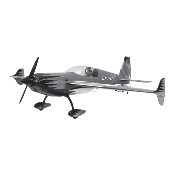
- Page 1 Extra 300 X 120cc Instruction Manual Bedienungsanleitung Manuel d’utilisation Manuale di Istruzioni...
- Page 2 SPECIFICATIONS • SPEZIFIKATIONEN • SPÉCIFICATIONS • SPECIFICHE LARGE PARTS LAYOUT • BAUTEILE (OHNE KLEINTEILE) • GRANDES PIÈCES • SCHEMA DEI COMPONENTI GRANDI 105 in (2.65 m) 2003 sq in (129 dm2) Total/Totale 98 in (2.5 m) 27–31 lbs (12.2–14.1 kg) 2-Stroke Gas •...
- Page 3 Extreme Big Tote Double 59 x 35 x 22 inch Rot & Sac de transport pour 2 ailes Extreme Big Tote 150 x WGT211 Custodie Alari 150 X 90 X 55 cm Rosse e Nere Red & Black Wing Bag Schwarz Flächentasche 90 x 55 cm rouge/noir Extra 300 X 120cc...
- Page 4 28 kg/cm. 400 oz/in HAN9160 (7) Aluminum Servo Arm, 2-inch (JR/SPM) Hangar 9 Aluminium Servo Arm, 2” (JR/SPM) Palonnier de servo en aluminium, long 50mm (JR,SPM) Squadretta servo in alluminio 5cm (JR/SPM) Heavy Duty Servo Extension 18-inch Servokabelverlängerung 460 mm...
- Page 5 Side cutters Seitenschneider Pince coupante Lama laterale Square Geodreieck Équerre Squadra Tap and drill set, English Gewindeschneider und Bohrerset Taraud et foret Set punte e maschi, Inglese Tap Handle Halter für Gewindeschneider Épingles Impugnatura per maschiare Extra 300 X 120cc...
-
Page 6: Before Starting Assembly
NOTICE Batteries Always follow the manufacturer’s instructions when using and disposing of any batteries. Mishandling of Li-Po All instructions, warranties and other collateral documents are subject to change at the sole discretion of Horizon batteries can result in fi re causing serious injury and damage. Hobby, LLC. -
Page 7: Empfehlungen Zum Sicheren Betrieb
Fliegen Fliegen Sie um Sicherheit garantieren zu können, nur in weiten offenen Gegenden. Wir empfehlen hier den Betrieb auf zugelassenen Modellfl ugplätzen. Bitte beachten Sie lokale Vorschriften und Gesetze, bevor Sie einen Platz zum Fliegen wählen. Extra 300 X 120cc... -
Page 8: Avant De Commencer L'assemblage
REMARQUE L’hélice Gardez éloignés tous les éléments qui pourraient être attrapés par l’hélice. Cela inclut les vêtements larges ou les La totalité des instructions, garanties et autres documents est sujette à modifi cation à la seule discrétion d’Horizon objets comme des outils par exemple. Gardez toujours vos mains à distance pour éviter tout cas de blessures. Hobby, LLC. - Page 9 Horizon Hobby di competenza. Volo Per sicurezza volare solo in aree molto ampie. Meglio se in campi volo autorizzati per modellismo. Consultare le ordinanze locali prima di scegliere luogo dove volare. Extra 300 X 120cc...
- Page 10 BUILDING PRECAUTIONS HINWEISE ZUM BAU PRÉCAUTIONS D’ASSEMBLAGE PRECAUZIONI PER LA COSTRUZIONE The wings of your model are constructed using a balsa Die Tragfl ächen des Modells bestehen aus einem Les ailes de votre modèle sont fabriquées en mousse L’ala di questo modello è costruita in polistirolo sheeted foam core to aid in reducing the weight of your Balsaholz beplankten Styroporkern.
- Page 11 11. Repeat the previous steps to install the control horns toward the wing tip. 12. Repeat this section to install the control horns in the opposite aileron. Extra 300 X 120cc...
-
Page 12: Aileron Servo Installation
AILERON SERVO INSTALLATION Install the grommets and brass eyelets in the servos. Insert the servo extension into the hole in the wing at the Follow any instructions included with the servo. Prepare location for the tip servo. both the root and tip aileron servos. Enlarge the holes for the servo mounting screws using a Guide the servo lead through the area for the root aileron drill and 5/64-inch (2mm) drill bit. -
Page 13: Elevator Servo Installation
4-40 x 5/8 socket head cap screw and 4-40 locknut as the hardware for this step. Use a 3/32-inch hex wrench and 1/4-inch nut driver to tighten the hardware. Extra 300 X 120cc... - Page 14 Center the elevator servo using the radio system. Attach Cut the remaining the hook and loop strap into two equal the servo arm to the servo parallel to the elevator hinge pieces using scissors. Secure the receiver in the fuselage. line.
-
Page 15: Rudder Installation
13. Route the extensions forward inside the fuselage. Notches are located in the formers to route the extensions through, keeping them from getting tangled inside the fuselage. Extra 300 X 120cc... -
Page 16: Tail Wheel Installation
Prepare and install the rudder control horn, starting with Attach the ball link to the rudder servo arm. the upper horn. Check that the rudder rests perpendicular to your work surface when the rudder is resting on the control horn and hinge line as shown using a square. Repeat the process to install the lower control horn. -
Page 17: Stabilizer Installation
Bend the loops tightly against the tiller using two of the screws prepared in the previous step. arms to secure them in position. Use a 3/32-inch hex wrench to tighten the screws. Repeat the previous steps to install the remaining stabilizer. Extra 300 X 120cc... -
Page 18: Landing Gear Installation
LANDING GEAR INSTALLATION Attach the landing gear to the fuselage using four 8-32 Place a drop of light machine oil on the axle, then slide x 3/4-inch socket head cap screws, four #8 washers the wheel on the axle. Secure the wheel using a 5/32- and four 8-32 lock nuts. - Page 19 Adjust the linkage so the carburetor is plywood to protect the module from vibrations. closed. Check the operation of the carburetor using the radio system and make any adjustments necessary to achieve full throttle. Extra 300 X 120cc...
-
Page 20: Wing Installation
13. Route and connect the leads necessary to operate the 18. Cut the cowling to fi t over the muffl er exhaust stacks. engine. Use tie wraps to secure the leads so they don’t Work slowly for the best results. interfere with the operation of the engine or become disconnected accidentally. - Page 21 #6 washers. Use a 3/32-inch cockpit using 30-minute epoxy. Allow the epoxy to fully hex wrench to tighten the screws. cure before proceeding. Attach the canopy to the fuselage using the hardware removed earlier in the manual. Extra 300 X 120cc...
-
Page 22: Decal Installation
DECAL INSTALLATION Apply the decals to your model using the photos located in this section of the manual and the box art from your model. Use a spray bottle and a drop of dish washing liquid or glass cleaner sprayed in the location of the decal to allow repositioning of the decal. -
Page 23: Center Of Gravity
Always install the control horns 90 degrees to the servo center line. Use sub-trim as a last resort to center the servos. We highly recommend re-binding the radio system once all of the control throws are set. This will keep the servos from moving to their endpoints until the transmitter and receiver connect. Extra 300 X 120cc... -
Page 24: Preflight Checklist
PREFLIGHT CHECKLIST DAILY FLIGHT CHECKS LIMITED WARRANTY Limitation of Liability HORIZON SHALL NOT BE LIABLE FOR SPECIAL, INDIRECT, • Charge the transmitter, receiver and motor battery for • Check the battery voltage of the transmitter battery. What this Warranty Covers INCIDENTAL OR CONSEQUENTIAL DAMAGES, LOSS OF your airplane. -
Page 25: Warranty And Service Contact Information
You are required to register with the FAA if you own this product. For up-to-date information on how to register with the FAA, please visit https://registermyuas.faa.gov/ For additional assistance on regulations and guidance on UAS usage, visit knowbeforeyoufl y.org/ Extra 300 X 120cc... - Page 26 MONTAGE DER QUERRUDERHÖRNER Schleifen Sie den unteren Teil des Ruderhorn an der in die Entfernen Sie die Ruderhörner vom Querruder. Geben Sie Tragfäche gesteckt wird mit mittleren Schleifpapier an. etwas 30 Minuten Epoxy in den Schlitz des Querruders. Reingen Sie die angeschlifffene Oberfl äche mit einem Streichen Sie mit einem Zahnstocher etwas 30 Minuten Papiertuch und Reinigungsalkohol.
- Page 27 Schließen Sie eine 460mm lange Servoverlägerung 10. Schrauben Sie eine 4-40 x 5/8 Inbusschraube in an das äußere Servo an und sichern diese mit einer den Kugelanschluss. Schieben Sie die konische Verbindungssicherung. Unterlegscheibe mit dem gebogenen Ende zur Kugel auf. Extra 300 X 120cc...
- Page 28 11. Drehen Sie die Inbusschraube in das Loch des Servoarms 16. Justieren Sie die Anlenkung um das Querruder zu das 44mm von der Mitte des Servos entfernt ist. zentrieren während die Fernsteuerung das Servo neutral hält. Mit dem Pro Link Schlüssel (HAN3558) können Sie diese Einstellungen leicht vornehmen.
- Page 29 Teile und befestigen Sie damit notwendig zu öffnen. Schließen Sie den Schalter und das beiden Empfängerakkupacks. Legen Sie unter den Akku Datenkabel (nicht im Lieferumfang) an den Empfänger im Schaumstoff um diese vor Vibrationen zu schützen. Rumpf an. Extra 300 X 120cc...
- Page 30 Sichern Sie die 600mm EC3 Verlängerung an den Akku 14. Schließen Sie die 920mm Verlängerungen für die mit Kabelbinder. Höhenruderservos an den Empfänger an. 10. Führen Sie die Verlängerung durch den Rumpf und EINBAU DES SEITENRUDERS sichern diese in den Spanten mit Kabelbinder. Bereiten Sie das Ruderservo mit einsetzen der Gummipuffer und Messingeinsätze vor.
-
Page 31: Montage Des Spornrads
Sekundenkleber vollständig trocknen bevor Sie weiter machen. Schließen Sie den Kugelkopfanschluss an den Servoarm Montieren Sie den Hebelarm an der Unterseite des Ruders mit zwei 4 x5/8 inch selbstschneidenen Schrauben. Ziehen Sie die Schrauben mit einem 3/32 Sechskantschlüssel an. Extra 300 X 120cc... - Page 32 EINBAU DES HÖHENLEITWERKS Drehen Sie eine 6-32 x 3/4- Sechkantschraube in jedes Schieben Sie den Leitwerksverbinder in die Öffnung am der Löcher mit Einschlagmutter. Schneiden Sie falls Höhenruder. Der Verbinder sollte so einfach einzuführen sein, so dass dabei keine Kraft nötig sein sollte. notwendig die Gewinde mit einem 6-32 Gewindescheider nach.
- Page 33 Motorbox mit dem Abtrieb nach vorne ein. Markieren dass der Stellring mit der Schrauböffnung über der Sie die Schraublöcher mit einem Faserstift. fl achen Stelle ausgerichtet ist. Verwenden Sie hier Schraubensicherungslack damit sich die Madenschraube nicht lösen kann. Extra 300 X 120cc...
- Page 34 Bohren Sie mit einem 2mm Bohrer die vier Nach Montage der Anlenkung läuft diese parallel zur der Befestigungslöcher. Unterseite der Motorbox. Bereiten Sie jedes der Löcher mit eindrehen einer Schneiden Sie zwei 3,8cm lange Schlitze hinter die Schraube vor. Drehen Sie die Schraube wieder heraus Schlitze an der Oberseite der Motorbox.
-
Page 35: Montage Der Tragflächen
Motorhaube anzupassen. 17. Montieren Sie die Schalldämpfer am Motor mit dem im Lieferumfang des Schalldämpfers befi ndlichen Schieben Sie die Tragfl äche in Position und führen dabei Schrauben. die Verlängerungen von der Tragfl äche in den Rumpf. Extra 300 X 120cc... - Page 36 MONTAGE DER OPTIONALE SIDEFORCE GENERATOREN. Sichern Sie die Trafgfl äche mit den beiden 1/4 - 20 x 2 Entfernen Sie die Bespannung mit einem Hobbymesser Nylon Flächenbolzen. Drehen Sie den Bolzen in der Nähe im die bereits vormontierten Einschlagmuttern frei zu legen.
- Page 37 Sprühfl asche mit einem Tropfen Spülmittel. Positionieren Sie auf der angefeuchteten Fläche den Dekorbogen und wischen dann mit einem Papiertuch auf dem Dekorbogen das darunter befi ndliche Wasser über die Kanten raus. Lassen Sie den Bogen über Nacht trocknen, so dass das restliche Wasser verdunsten kann. Extra 300 X 120cc...
-
Page 38: Der Schwerpunkt
DER SCHWERPUNKT RUDERAUSSCHLAG Ein wichtiger Teil in der Vorbereitung des Flugzeug ist das korrekt einrichten des Schwerpunktes. Den Sender und Empfänger des Modells einschalten. Die Bewegung des Seitenruders mit der Fernsteuerung prüfen. Wird der Steuerhebel nach rechts bewegt, sollte sich auch das Seitenruder nach rechts bewegen. Die Montieren Sie die Tragfl... -
Page 39: Garantie Und Service Informationen
(c) Ansprüche des Käufers ¬ Es liegt ausschließlich zurückzugeben. im Ermessen von Horizon, ob das Produkt, bei dem ein Garantiefall festgestellt wurde, repariert oder ausgetauscht wird. Dies sind die exklusiven Ansprüche des Käufers, wenn ein Defekt festgestellt wird. Extra 300 X 120cc... -
Page 40: Garantie Und Service Kontaktinformationen
Sicherheitshinweise Fragen, Hilfe und Reparaturen Bitte legen Sie dem Produkt einen Kaufbeleg bei, sowie ACHTUNG: Kostenpfl ichtige Reparaturen nehmen wir Dieses ist ein hochwertiges Hobby Produkt und kein Ihr lokaler Fachhändler und die Verkaufstelle können eine ausführliche Fehlerbeschreibung und eine Liste aller nur für Elektronik und Motoren vor. -
Page 41: Installation Des Guignols D'aile
Retirez la vis du guignol une fois que la colle pour une meilleure fi nition. est complètement sèche. 11. Répétez les étapes pour installer les guignols vers le saumon d’aile. 12. Répétez cette section pour installer les guignols sur l’aileron opposé. Extra 300 X 120cc... -
Page 42: Installation Des Servos D'ailerons
INSTALLATION DES SERVOS D’AILERONS Installez les silent-blocs sur le servo. Suivez les Insérez la rallonge servo dans le trou de l’aile destiné au instructions fournies avec le servo. Préparez les servos servo d’extrémité. d’emplanture et d’extrémité. Élargissez les trous des vis de fi xation de servo à l’aide Guidez le câble servo vers la zone du servo de d’une mini perceuse et d’un foret 2mm. -
Page 43: Installation Du Servo De Profondeur
écrou auto-freiné 4-40. Utilisez une clé BTR 3/32-inch et et un écrou auto-freiné 4-40 comme visserie pour cette une clé à écrou 1/4-inch pour serrer la visserie. étape. Utilisez une clé BTR 3/32-inch et une clé à écrou 1/4-inch pour serrer la visserie. Extra 300 X 120cc... -
Page 44: Installation Du Récepteur Et De La Batterie
Centrez le servo de profondeur avec votre radio. Attachez Coupez la sangle auto-agrippante restante en deux le palonnier de servo afi n qu’il soit parallèle à l’axe de parts égales à l’aide de ciseaux. Fixez le récepteur dans charnière. Faites les réglages nécessaires sur le servo le fuselage. -
Page 45: Installation De La Dérive
Évitez de les emmêler dans le fuselage. avec le guignol supérieur. Vérifi ez que la dérive est perpendiculaire à votre surface de travail lorsque la dérive repose contre le guignol et l’axe de charnière comme sur l’illustration en utilisant une équerre. Extra 300 X 120cc... -
Page 46: Installation De La Roulette De Queue
Répétez le processus pour installer le guignol inférieur. Centrez le servo de dérive à l’aide de votre radio. Attachez Laissez la colle epoxy sécher complètement avant de le palonnier de servo. Placez le palonnier sur le servo de dérive à la perpendiculaire de la ligne centrale du servo. continuer. -
Page 47: Installation Du Stabilisateur
Glissez le stabilisateur contre le fuselage. Fixez-le à l’aide de deux des vis préparées dans l’étape précédente. Utilisez une clé BTR 3/32-inch pour serrer les vis. Répétez les étapes précédentes pour installer le stabilisateur restant. Extra 300 X 120cc... -
Page 48: Installation Du Train D'atterrissage
INSTALLATION DU TRAIN D’ATTERRISSAGE Installez le train d’atterrissage sur le fuselage à l’aide Mettez une goutte de lubrifi ant sur l’axe puis installez la de quatre vis BTR 8-32 x 3/4-inch, quatre rondelles #8 roue sur l’axe. Fixez la roue à l’aide d’une bague d’arrêt et quatre écrous auto-freinés 8-32. -
Page 49: Installation Du Moteur
Guides les câbles de la batterie 7/64-inch. dans le trou situé en haut du bâti moteur. Extra 300 X 120cc... - Page 50 11. Découpez l’entoilage sur le côté du fuselage en utilisant 16. Découpez l’échappement du silencieux d’une longueur un couteau de modélisme avec une lame #11. Installez de 61mm. Cela facilitera l’installation du capot sur le l’interrupteur d’allumage en utilisant la visserie fournie silencieux.
-
Page 51: Installation Du Pilote Et De La Verrière
à cause des vibrations mais vous devez toujours pouvoir les retirer. Fixez le générateur d’appui latéral à l’extrémité de l’aile avec deux vis à tête bombée 6-32 x 3/4-inch et deux rondelles #6. Utilisez une clé BTR 3/32-inch pour serrer les vis. Extra 300 X 120cc... -
Page 52: Pose Des Autocollants
POSE DES AUTOCOLLANTS Appliquez les autocollants sur votre modèle en vous basant sur les illustrations de cette section. Utilisez un pulvérisateur d’eau avec une goutte de liquide vaisselle ou du produit de nettoyage vitres à l’emplacement de l’autocollant pour pouvoir le repositionner. Utilisez du papier absorbant pour essuyer l’excès d’eau sous l’autocollant. -
Page 53: Centre De Gravité
Nous vous recommandons de ré-affecter votre radio quand tous les réglages de débattements sont effectués. Cela empêchera les servos d’aller en butée lors de la connexion de l’émetteur et du récepteur. Extra 300 X 120cc... -
Page 54: Contrôles Systématiques
CHECKLIST D’AVANT VOL CONTRÔLES SYSTÉMATIQUES GARANTIE ET RÉPARATIONS Limitation des dommages Horizon ne saurait être tenu pour responsable de • Chargez la batterie de votre émetteur, de réception • Contrôlez la tension de la batterie de l’émetteur. Durée de la garantie dommages conséquents directs ou indirects, de pertes et d’allumage. -
Page 55: Coordonnées De Garantie Et Réparations
Pour plus d’informations sur les points de collecte de vos équipements usagés en vue du recyclage, veuillez contacter votre mairie, votre service de collecte des ordures ménagères ou le magasin dans lequel vous avez acheté le produit. Extra 300 X 120cc... - Page 56 INSTALLAZIONE DELLE SQUADRETTE ALETTONI Grattare con carta vetrata media la parte inferiore della Togliere la squadretta dall’alettone. Mettere una piccola squadretta, quella che si infi la nell’alettone. quantità di colla epoxy 30 minuti in entrambe le fessure sull’alettone. Con un fazzoletto di carta e alcol isopropilico, pulire le Con uno stuzzicadenti mettere una piccola quantità...
- Page 57 10. Inserire una vite a brugola da 4-40x5/8” nell’attacco a una prolunga da 460mm fi ssandola con un sistema sfera del rinvio. Inserire la rondella conica sulla vite con la commerciale. parte più piccola contro la sfera in metallo. Extra 300 X 120cc...
- Page 58 11. Avvitare la vite a brugola nel foro della squadretta del 16. Regolare il rinvio in modo da centrare l’alettone servo che si trova a 44mm dal centro. mantenendo il servo centrato con il radiocomando. Per facilitare la regolazione usare una chiave Pro-Link (HAN3558).
- Page 59 Fissare nella fusoliera le due batterie per la necessità. Collegare l’interruttore e il cavo dati (non ricevente. Mettere della spugna tra il compensato e le forniti) alla ricevente, all’interno della fusoliera. batterie per isolarle dalle vibrazioni. Extra 300 X 120cc...
-
Page 60: Installazione Del Timone
Fissare la prolunga EC3 alle batterie usando delle 14. Collegare le prolunghe servo da 920mm alla ricevente per fascette. i servi elevatore. 10. Far passare la prolunga lungo la fusoliera fi ssandola alle INSTALLAZIONE DEL TIMONE ordinate con delle fascette. Preparare il servo del timone montando su di esso gommini e occhielli. -
Page 61: Installazione Del Ruotino Di Coda
CA sia completamente asciutta. Fissare l’attacco a sfera alla squadretta del servo del timone. Fissare la squadretta di guida alla parte inferiore del timone usando le viti autofi lettanti #4x5/8” e stringendole con una chiavetta esagonale da 3/32”. Extra 300 X 120cc... -
Page 62: Installazione Dello Stabilizzatore
INSTALLAZIONE DELLO STABILIZZATORE Avvitare una vite a brugola da 6-32x3/4” in ciascuno dei Inserire il tubo dello stabilizzatore nella sua sede su di fori ciechi pronti in fusoliera. Pulire i fori con un maschio esso. Il tubo si dovrebbe inserire facilmente, perciò non è da 6/32”... -
Page 63: Installazione Del Carrello
Con delle vibrazioni. una matita segnare la posizione delle viti di fi ssaggio del servo. Extra 300 X 120cc... - Page 64 Praticare i quattro fori di fi ssaggio con una punta da Quando il rinvio è stato installato, si muoverà parallelo 2mm. alla parte inferiore della scatola motore. Preparare i fori di fi ssaggio avvitando in essi una vite e Tagliare due fessure aggiuntive da 38mm a 38mm dietro poi togliendola.
-
Page 65: Installazione Dell'ala
Installare un silenziatore per volta per facilitare la rifilatura della capottina motore. 17. Fissare i silenziatori al motore con le viti fornite insieme ad essi. Posizionare la semiala inserendo nella fusoliera le prolunghe che escono dalla semiala. Extra 300 X 120cc... - Page 66 INSTALLAZIONE GENERATORI DI SPINTA LATERALE (OPZIONALI) Fissare le semiali alla fusoliera con due viti in nylon Con un tagliabalsa togliere il rivestimento per scoprire il da 1/4-20x2”. Installare le viti vicino al bordo di uscita dado cieco preinstallato all’estremità dell’ala. dell’ala, senza stringerle completamente.
-
Page 67: Applicazione Delle Decalcomanie
Usare un fazzoletto di carta per togliere l’eccesso di acqua che si trova sotto alle decals. Lasciare riposare il modello per una notte in modo che l’acqua rimasta possa evaporare. Extra 300 X 120cc... -
Page 68: Baricentro (Cg)
BARICENTRO (CG) CORSE DEI COMANDI Una parte molto importante nella preparazione del modello per il volo, è il suo bilanciamento. Accendere trasmittente e ricevente del modello. Verifi care il movimento del timone agendo sulla trasmittente. Quando si sposta lo stick verso destra il timone deve andare a destra. Se necessario invertire la direzione del Fissare l’ala alla fusoliera. -
Page 69: Lista Dei Controlli Prima Del Volo
Solo o disposizione applicabile, negligenza, uso ai fi ni così si eviterà un utilizzo errato e si preverranno incidenti, commerciali, o una qualsiasi modifi ca a qualsiasi parte lesioni o danni. del prodotto. Extra 300 X 120cc... -
Page 70: Contatti Per La Garanzia E L'assistenza
Domande, assistenza e riparazioni Garanzia e riparazione ATTENZIONE: Le riparazioni a pagamento sono Il vostro negozio locale e/o luogo di acquisto non Le richieste in garanzia verranno elaborate solo se è disponibili solo sull’elettronica e sui motori. Le possono fornire garanzie di assistenza o riparazione presente una prova d’acquisto in originale proveniente riparazioni a livello meccanico, soprattutto per senza previo colloquio con Horizon. - Page 71 -inches (298.5mm) -inches (1187.5mm) 43-inches (1092.2mm) 29-inches (736.6mm) -inches (2527.3mm) 25-inches (635mm) -inches (730.3mm) 88-inches (2235.2mm) Extra 300 X 120cc...
- Page 72 © 2016 Horizon Hobby, LLC. Hangar 9, DSMX, EC3, PowerSafe and the Horizon Hobby logo are trademarks or registered trademarks of Horizon Hobby, LLC. The Spektrum trademark is used with permission of Bachmann Industries, Inc. All other trademarks, service marks and logos are the property of their respective owners. Patents pending.