
Manuels Connexes pour Hangar 9 Sbach 342 60


Sommaire des Matières pour Hangar 9 Sbach 342 60
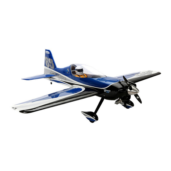
- Page 1 Instruction Manual ® Sbach 342 60 Bedienungsanleitung Manuel d’utilisation Manuale di Istruzioni...
-
Page 2: Safety Warnings And Precautions
NOTICE SAFETY WARNINGS AND PRECAUTIONS SAFE OPERATING RECOMMENDATIONS All instructions, warranties and other collateral documents are subject to change at the sole discretion of Horizon Hobby, Read and follow all instructions and safety precautions • Inspect your model before every fl ight to ensure it is Inc. -
Page 3: Warnungen Und Sicherheit- Svorkehrungen
WARNUNGEN UND SICHERHEIT- EMPFEHLUNGEN ZUM SICHEREN HINWEIS SVORKEHRUNGEN BETRIEB Alle Anweisungen, Garantien und anderen zugehörigen Dokumente können im eigenen Ermessen von Horizon Hobby, Inc. jederzeit geändert werden. Die aktuelle Produktliteratur fi nden Sie auf horizonhobby.com unter der Registerkarte „Support“ Bitte lesen und befolgen Sie alle Anweisungen und •... -
Page 4: Avertissements Relatifs À La Sécurité
REMARQUE AVERTISSEMENTS RELATIFS À LA CONSIGNES DE SÉCURITÉ CONCERNANT SÉCURITÉ L’UTILISATION La totalité des instructions, garanties et autres documents est sujette à modifi cation à la seule discrétion d’Horizon Hobby, Inc. Pour obtenir la documentation à jour, rendez-vous sur le site horizonhobby.com et cliquez sur l’onglet de support de ce Lisez et suivez toutes les instructions relatives à... -
Page 5: Avvertimenti E Precauzioni Per La Sicurezza
AVVERTIMENTI E PRECAUZIONI PER LA RACCOMANDAZIONI PER OPERARE IN AVVISO SICUREZZA SICUREZZA Tutte le istruzioni, le garanzie e gli altri documenti pertinenti sono soggetti a cambiamenti a totale discrezione di Horizon Hobby, Inc. Per una documentazione aggiornata sul prodotto, visitare il sito www.horizonhobby.com e fare clic sulla sezione Prima dell’uso leggere attentamente tutte le istruzioni e le •... - Page 6 SPECIFICATIONS•SPEZIFIKATIONEN• LARGE PARTS LAYOUT•BAUTEILE (OHNE KLEINTEILE)• SPÉCIFICATIONS•SPECIFICHE ELÉMENTS PRINCIPAUX•SCHEMA DEI COMPONENTI GRANDI 62.0 in (1575mm) 860 sq in (55.5 dm2) 60.0 in (1524mm) 7.5–8.5 lb (3.4–3.9 kg) 2-Stroke Glow•2-Takt Glühzünder• 2 temps méthanol•2-Tempi Glow .52–.61 4-Stroke Glow•4-Takt Glühzünder• 4 temps méthanol•4-Tempi Glow .91–1.25 2-Stroke Gas/Petrol•2-Takt Benziner•...
- Page 7 REPLACEMENT PARTS•ERSATZTEILE•PIÈCES DE RECHANGE•RICAMBI Part English Deutsch Français Italiano HAN421501 Fuselage with Hatch Rumpf mit Haube Fuselage avec trappe Fusoliera con portello HAN421502 Hatch with Canopy Öffnung mit Kabinenhaube Trappe avec verrière Naca pilota HAN421503 Wing Set Tragfl ächenset Paire d’ailes Set ali HAN421505 Stabilizer and Elevator Set...
- Page 8 ASSEMBLY SYMBOL GUIDE•MONTAGE SYMBOLE•GUIDE DES SYMBOLES POUR ASSEMBLAGE•GUIDA AI SIMBOLI DI ASSEMBLAGGIO Apply threadlock Ensure free rotation Use medium CA Use a pencil Schraubensicherungslack verwenden Rotation sicherstellen Mittelfl üssigen Verwenden Sie einen Bleistift Sekundenkleber verwenden Utilisez du frein fi let Permettez une rotation libre Utilisez un crayon à...
- Page 9 REQUIRED RADIO EQUIPMENT•ERFORDERLICHE RC AUSRÜSTUNG•EQUIPEMENT RADIO REQUIS•APPARECCHIATURE RADIO Part # English Deutsch Français Italiano ® SPMAR8000 AR8000 8-Channel DSMX Receiver AR8000 8-Kanal DSMX Receiver Récepteur 8 voies DSMX AR8000 Ricevitore AR8000 DSMX a 8 canali JRPS821HV (5, 4 for EP) DS821HV HV Digital Sport High Torque Servo DS821HV HV Digital Sport High Torque Servo Servo DS821 HV digital, couple élevé...
- Page 10 ELECTRIC POWER•ELEKTROANTRIEB•MOTEUR ELECTRIQUE (EP)•MOTORE ELETTRICO EFLM4060B Power 60 Brushless Outrunner Motor, 470Kv E-fl ite Power 60 BL AL-Motor 470U/V Moteur Power 60 Brushless à cage tournante 470Kv Power 60 Motore brushless cassa rotante, 470Kv EFLA1080B 80-Amp Pro Switch-Mode BEC E-fl ite 80-Amp Pro Switch-Mode BEC Contrôleur brushless 80A Pro switch-mode BEC, ESC 80A con BEC switching, EC5 (V2) Brushless ESC, EC5...
- Page 11 REQUIRED TOOLS•BENÖTIGTES WERKZEUG•OUTILS REQUIS•ATTREZZI NECESSARI English Deutsch Français Italiano Drill bit: 1/16-inch, 5/64-inch, 1/8-inch, 11/64-inch Bohrer: 1,5 mm, 2mm, 3mm, 4,5mm Foret : 1,5 mm, 2mm, 3mm, 4,5mm Punte per trapano: 1,5 mm, 2mm, 3mm, 4,5mm Felt-tipped pen Faserstift Feutre fi n effaçable PennarelloFlat blade screwdriver: Small Hemostat Klemme...
-
Page 12: Before Starting Assembly
BEFORE STARTING ASSEMBLY VOR DEM ZUSAMMENBAU AVANT DE COMMENCER L’ASSEMBLAGE PRIMA DI INIZIARE IL MONTAGGIO • Remove parts from bag. • Entnehmen Sie zur Überprüfung jedes Teil der Verpackung. • Retirez toutes les pièces des sachets pour les inspecter. • Togliere tutti i pezzi dalla scatola. •... - Page 13 AILERON SERVO INSTALLATION•EINBAU DER QUERRUDERSERVOS•INSTALLATION DES SERVOS D’AILERONS•INSTALLAZIONE SERVI ALETTONI Prepare the aileron servos by installing the grommets and eyelets. Setzen Sie in die Querruderservos die Gummitüllen und Thread a servo mounting screw into each of the holes in the Apply a small amount of thin CA to harden the threads made Secure the servo to the cover using the screws provided with Blechösen ein.
- Page 14 M2 x 10 Center the servos using the radio system and install the servo arms so they are perpendicular to the servo center line. Enlarge the hole in the servo arm using a 5/64-inch (2mm) Thread a screw into each of the holes in the aileron servo Apply a small amount of thin CA to harden the threads made drill bit that is 1 inch (25mm) from the center of the servo cover mounting holes.
- Page 15 LANDING GEAR INSTALLATION• EINBAU DES FAHRWERKS• INSTALLATION DU TRAIN D’ATTERRISSAGE• INSTALLAZIONE DEL CARRELLO M2 x 10 Secure the servo cover to the wing using four M1.5 x 10 self- Attach the 2 -inch (72mm) linkage to the servo arm using Slide a silicone retainer over the clevis.
- Page 16 RUDDER INSTALLATION•EINBAU DES SEITENRUDERS• INSTALLATION DE LA DÉRIVE•INSTALLAZIONE DEL TIMONE 4-40 x 1/2-inch Attach the wheel pants to the landing gear. Apply a small amount of petroleum jelly to the tail gear wire Use sandpaper to lightly sand the tail wheel wire where it near the bushing.
- Page 17 Use a pin vise and 1/16-inch (1.5mm) drill bit to drill a hole Use a pin vise and 1/8-inch (3mm) drill bit to drill a hole in Cut a slot from the hole drilled in the previous step to the in the center of each hinge slot.
- Page 18 Check the fi t of the rudder to the fuselage. Make sure the tail wheel wire fi ts into the rudder, and that the notch fi ts over the tail wheel bushing. There should be no gap between the Once the epoxy fully cures, apply thin CA to both sides of fi...
- Page 19 RUDDER SERVO INSTALLATION•EINBAU DES SEITENRUDERSERVOS•INSTALLATION DU SERVO DE DIRECTION•INSTALLAZIONE SERVO DEL TIMONE Slide the canopy hatch forward and up to release, then aft to Thread a servo mounting screw into each hole to cut threads remove it from the fuselage. in the surrounding wood.
- Page 20 Install the grommets and brass eyelets in the rudder servo. Insert the Z-bend of the 29 -inch (755mm) pushrod in the Slide the rudder pushrod into the pushrod tube. Use the radio Secure the rudder servo in the fuselage using the screws servo arm to be used for the rudder.
- Page 21 STABILIZER INSTALLATION•MONTAGE DES HÖHENLEITWERKS•INSTALLATION DU STABILISATEUR•INSTALLAZIONE DELLO STABILIZZATORE Use sandpaper to lightly sand the elevator joiner wire where it will fi t into the elevators. Slide the aluminum stabilizer joiner rod into the pocket in the Schleifen Sie den Leitwerksverbinderdraht an den Stellen an stabilizer.
- Page 22 ELEVATOR INSTALLATION•MONTAGE DES HÖHENRUDERS• INSTALLATION DES GOUVERNES DE PROFONDEUR•INSTALLAZIONE DELL’ELEVATORE Slide the stabilizers and stabilizer tube back into position. Stand back from the fuselage and check to make sure the stabilizers are square to the rudder. Use low-tack tape to Apply a small amount of epoxy in the pocket of each hold the stabilizers in position until the epoxy fully cures.
- Page 23 Wrap a piece of low-tack tape around the stabilizer in the area of the joiner wire to help prevent gluing the joiner wire to the stabilizer. Fit the elevators into position, guiding the joiner wire into the stabilizers. Remove the T-pins so the gap between the stabilizer and elevators can be minimized.
- Page 24 ELEVATOR LINKAGE INSTALLATION•MONTAGE DES HÖHENRUDERGESTÄNGES• INSTALLATION DE LA COMMANDE DE PROFONDEUR•INSTALLAZIONE DEI COMANDI ELEVATORE Mount the elevator servo in the fuselage using the hardware Insert the Z-bend of the 28 -inch (725mm) pushrod in Slide the elevator pushrod into the pushrod tube. Use the provided with the servo.
- Page 25 GLOW ENGINE INSTALLATION•GLÜHZÜNDEREINBAU•INSTALLATION DU MOTEUR MÉTHANOL•INSTALLAZIONE DEL MOTORE GLOW 8-32 8-32 x 1 inch Check the orientation of the carburetor in relationship to the engine. It may be necessary to reposition the carburetor and/or throttle arm so the engine can be installed on this Secure the engine mount rails to the fi...
- Page 26 Connect the throttle pushrod to the throttle arm in the center Position the engine so the drive washer is 5 inches Use a drill and 5/32-inch (4mm) drill bit to drill the holes for hole as shown in the photo. (137mm) forward of the fi...
- Page 27 FUEL TANK AND THROTTLE SERVO INSTALLATION•EINBAU DES KRAFTSTOFFTANKS UND GASSERVO•INSTALLATION DU RÉSERVOIR ET DU SERVO• INSTALLAZIONE SERBATOIO E SERVO MOTORE 8-32 8-32 x 1 inch Bend the throttle pushrod so it will align with the throttle servo when it is installed. Make sure the pushrod can still move without any binding.
- Page 28 Use a pin vise and 5/64-inch (2mm) drill bit to drill the holes for the servo mounting screws. Apply a small amount of thin CA to harden the threads made Place the throttle servo into position. Mark the location for Bohren Sie mithilfe eines Feilklobens und eines 2-mm- in the previous step.
- Page 29 RECEIVER INSTALLATION FOR GLOW ENGINE INSTALLATION• EMPFÄNGEREINBAU FÜR GLÜHZÜNDER• INSTALLATION DU RÉCEPTEUR DANS LE CAS D’UN MOTEUR MÉTHANOL• INSTALLAZIONE DEL RICEVITORE QUANDO SI USA UN MOTORE GLOW Slide the connector over the pushrod wire. Center the throttle stick and trim, then attach the arm perpendicular to the servo center line.
- Page 30 4-40 x 1/2-inch Secure the receiver battery in the fuselage using 1/4-inch Use hook and loop straps and 1/4-inch (6mm) foam rubber (6mm) foam and a hook and loop strap. Connect the lead to secure the receiver in the fuselage. Make sure to connect from the battery to the correct lead of the switch.
- Page 31 EP MOTOR INSTALLATION•EINBAU DES ELEKTRO MOTORS• INSTALLATION DU MOTEUR ÉLECTRIQUE•INSTALLAZIONE MOTORE ELETTRICO Mount the remote receiver in the fuselage using hook and loop tape. 6-32 x 1/2-inch 6-32 Montieren Sie den Satellitenempfänger im Rumpf mit The motor shaft must be repositioned to allow the Klettband.
- Page 32 4-40 x 1/2-inch Place the hook and loop straps in position in the battery tray. The front strap will go around the speed control to help keep in position. The rear strap must not interfere with the wiring Secure the motor to the motor box using the hardware Secure the battery tray mounts in the fuselage.
- Page 33 COWLING AND SPINNER INSTALLATION•MONTAGE DES SPINNER UND DER MOTORHAUBE•INSTALLATION DU CAPOT ET DU CÔNE• INSTALLAZIONE DI CAPOTTINA E OGIVA Connect the leads from the speed control to the motor. Apply hook tape to the battery and loop tape to the battery Secure the wiring using tie wraps (not included) so they tray, then secure the battery to the battery tray using hook don’t interfere with the operation of the motor.
- Page 34 Slide the cowl on the fuselage. You may not be able to install any of the bolts depending on your engine selection. At this time, lining up the cowl close is suffi cient. Schieben Sie die Motorhaube auf den Rumpf. Es kann möglich sein dass sie je nach Motorauswahl die Befestigungsschrauben noch nicht eindrehen können.
- Page 35 WING INSTALLATION• MONTAGE DER TRAGFLÄCHEN• INSTALLATION DE L’AILE• MONTAGGIO DELL’ALA Prepare the engine mounting bolts by sliding the tapered Install the spinner back plate and propeller. Secure the Secure the spinner cone to the engine. Make sure the blades washer on the bolt. Remove the backing from the foam disk, propeller using the appropriate adapter nut suited to your of the propeller do not contact the cone.
- Page 36 1/4-20 x 1.5 inch Slide the wing panel into position, guiding the extensions from the wing into the fuselage. Secure the wing panels to the fuselage. Schieben Sie die Tragfl äche in die richtige Position. Führen Sie dabei die Verlängerungen vom Flügel in den Rumpf. Befestigen Sie die Tragfl...
-
Page 37: Center Of Gravity
CENTER OF GRAVITY DER SCHWERPUNKT CENTRE DE GRAVITÉ CENTRO DI GRAVITA’ (BARICENTRO) An important part of preparing the aircraft for fl ight is Ein sehr wichtiger Teil in der Flugvorbereitung ist es das Une des étapes importantes de la préparation d’un modèle Un punto importante per preparare l’aereo al volo è... -
Page 38: Control Throws
CONTROL THROWS RUDERAUSSCHLÄGE 1. Turn on the transmitter and receiver of your model. Check the movement of the rudder using the transmitter. When the stick 1. Schalten Sie den Sender und Empfänger ihres Modells ein. Prüfen Sie die Seitenruderaussschläge mit dem Sender. is moved to the right, the rudder should also move right. -
Page 39: Débattements
DÉBATTEMENTS CORSE DEI COMANDI 1. Mettez l’émetteur et le récepteur sous tension. Contrôlez les mouvements de la dérive en utilisant votre émetteur. Quand le 1. Accendere trasmettitore e ricevitore del modello. Controllare i movimenti del timone agendo sul trasmettitore. Quando manche est vers la droite, la dérive doit s’orienter vers la droite. -
Page 40: Preflight Checklist
PREFLIGHT CHECKLIST VORFLUGKONTROLLE CHECKLIST D’AVANT VOL LISTA DEI CONTROLLI PRIMA DEL VOLO • Charge the transmitter, receiver and motor battery for • Laden Sie den Sender- ,Empfänger- und Zündakku für • Chargez la batterie de votre émetteur, de réception • Caricare le batterie di trasmettitore, ricevitore e your airplane. -
Page 41: Daily Flight Checks
DAILY FLIGHT CHECKS TÄGLICHER FLUG CHECK CONTRÔLES SYSTÉMATIQUES CONTROLLI DI VOLO GIORNALIERI • Check the battery voltage of the transmitter battery. Do • Überprüfen Sie die Spannung des Senderakkus. Fliegen • Contrôlez la tension de la batterie de l’émetteur. Ne volez •... - Page 42 LIMITED WARRANTY What this Warranty Covers Limitation of Liability Inspection or Services Non-Warranty Service Horizon Hobby, Inc. (“Horizon”) warrants to the original HORIZON SHALL NOT BE LIABLE FOR SPECIAL, INDIRECT, If this Product needs to be inspected or serviced and is Should your service not be covered by warranty, service purchaser that the product purchased (the “Product”) will be INCIDENTAL OR CONSEQUENTIAL DAMAGES, LOSS OF...
-
Page 43: Garantie Und Service Informationen
GARANTIE UND SERVICE INFORMATIONEN Warnung Horizon behält sich vor, alle eingesetzten Komponenten zu Fragen, Hilfe und Reparaturen Sollten wir nach 90 Tagen keineEinverständniserklärung zur prüfen, die in den Garantiefall einbezogen werden können. Reparatur vorliegen haben, behalten wir uns vor, das Produkt Ein ferngesteuertes Modell ist kein Spielzeug. -
Page 44: Garantie Et Réparations
GARANTIE ET RÉPARATIONS Durée de la garantie La garantie ne couvre pas les dégâts résultant d’un montage Questions, assistance et réparations ATTENTION: nous n’effectuons de réparations ou d’une manipulation erronés, d’accidents ou encore du payantes que pour les composants électroniques Garantie exclusive - Horizon Hobby, Inc. - Page 45 GARANZIA Periodo di garanzia Limiti di danno Manutenzione e riparazione La garanzia esclusiva - Horizon Hobby, Inc., (Horizon) Horizon non si riterrà responsabile per danni speciali, Se il prodotto deve essere ispezionato o riparato, si prega di garantisce che i prodotti acquistati (il “Prodotto”) sono diretti, indiretti o consequenziali;...
-
Page 46: Instructions For Disposal Of Weee By Users In The European Union
WARRANTY AND SERVICE CONTACT INFORMATION•GARANTIE UND SERVICE KONTAKTINFORMATIONEN• COORDONNÉES DE GARANTIE ET RÉPARATIONS•GARANZIA E REVISIONA INFORMAZIONI PER I CONTATTI Country of Horizon Hobby Contact Information Address Purchase Horizon Service Center servicecenter.horizonhobby.com/RequestForm/ (Repairs and Repair Requests) www.quickbase.com/db/bghj7ey8c?a=GenNewRecord Horizon Product Support United States 4105 Fieldstone Rd (Product Technical Assistance) of America... -
Page 47: Ama National Model Aircraft Safety Code
AMA NATIONAL MODEL AIRCRAFT SAFETY CODE Effective January 1, 2013 (h) Not operate model aircraft while under the infl uence of B. RADIO CONTROL (RC) 7. Under no circumstances may a pilot or other person touch alcohol or while using any drug which could adversely affect a model aircraft in fl... - Page 48 © 2013 Horizon Hobby, Inc. Hangar 9, Evolution, Celectra, JR, DSMX, EC5, E-fl ite and the Horizon Hobby logo are trademarks or registered trademarks of Horizon Hobby, Inc. The Spektrum trademark is used with permission of Bachmann Industries, Inc. Sbach and its design are trademarks of STO Streicher GmbH & Co. KG registered in Germany and used with permission.