Publicité
Les langues disponibles
Les langues disponibles
Liens rapides
EDB94AxH6954
.8m8
All manuals and user guides at all-guides.com
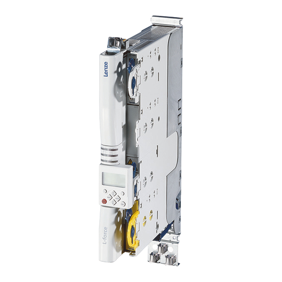
L-force
Drives
9400
1.5 ... 695 A
E94ASHExxxx Single Drive HighLine V03
Achsmodul
Axis module
Module d'axe
Módulos de eje
Modulo asse
Inbetriebnahme-Leitfaden
Commissioning guide
Guide de mise en service
Guía para la puesta en marcha
Guida per la messa in servizio
Publicité

Manuels Connexes pour Lenze Single Drive HighLine V03 E94ASHE Serie


Sommaire des Matières pour Lenze Single Drive HighLine V03 E94ASHE Serie
- Page 43 All manuals and user guides at all-guides.com 9400 HighLine | Guide de mise en service Sommaire Sommaire A propos de cette documentation ........... Conventions utilisées.
- Page 44 Tous les textes, photos et graphiques contenus dans cette documentation sont protégés par la loi sur les droits d'auteur. Aucune partie de cette documentation ne peut être reproduite ni transmise à des tiers sans l'accord écrit explicite de Lenze Drive Systems GmbH.
- Page 45 Type d'information Présentation Exemples / remarques Caractères spéciaux Nom de programme » « Le logiciel pour PC »Engineer« de Lenze... Fenêtre Italique La Fenêtre Message.../la boîte de dialogue Options... Elément de commande Gras Le bouton OK... / L'option Copier... / L'onglet Caractéristiques...
- Page 46 All manuals and user guides at all-guides.com 9400 HighLine | Guide de mise en service Consignes de sécurité Consignes de sécurité Danger ! L'utilisation du variateur comporte certains risques susceptibles d'entraîner la mort ou des blessures graves ou de causer des dommages matériels importants. Pour se prémunir contre ces risques, il est impératif de se conformer au consignes de sécurité...
- Page 47 All manuals and user guides at all-guides.com 9400 HighLine | Guide de mise en service Consignes de sécurité Protection du moteur Avec certains réglages du variateur, la température du moteur raccordé peut atteindre un niveau trop élevé. Exemples : – Fonctionnement prolongé du frein CC –...
- Page 48 – Système d'exploitation Microsoft® Windows® 2000 (à partir du Service Pack 2) ou Windows® XP le logiciel pour PC »Engineer« de Lenze. une liaison avec le variateur de vitesse. – Exemple : via interface de diagnostic X6 ou adaptateur de diagnostic USB...
- Page 49 All manuals and user guides at all-guides.com Etapes de la mise en service : Boîte de dialogue dans »Engineer« : Documentation connexe : 1. Démarrer »Engineer«. Manuel logiciel/aide en ligne du logiciel L-force »Engineer« 2. Dans l'Assistant de démarrage, sélectionner la Assistant de démarrage procédure.
- Page 50 • Les paramètres de trajectoire dépendent de l'application dans laquelle le variateur et le moteur sont utilisés. • Lorsqu'un moteur Lenze est sélectionné dans »Engineer«, des paramètres de trajectoire adaptés sont proposés pour un fonctionnement hors charge. Paramètre Information Réglage Lenze...
- Page 51 All manuals and user guides at all-guides.com 9400 HighLine | Guide de mise en service Mise en service avancée Adaptation du moteur et du variateur Détermination de l'angle de la roue polaire Remarque importante ! Requis uniquement dans les cas suivants : •...
- Page 52 All manuals and user guides at all-guides.com 9400 HighLine | Guide de mise en service Mise en service avancée Adaptation du moteur et du variateur Optimisation des caractéristiques de commutation de l'onduleur Remarque importante ! • En cas de régulation Servo, nécessaire uniquement en cas de fonctionnement du variateur avec un moteur d'un autre fabricant ! •...
- Page 53 All manuals and user guides at all-guides.com 9400 HighLine | Guide de mise en service Mise en service avancée Adaptation du moteur et du variateur Définition des paramètres du moteur Remarque importante ! • En cas de régulation Servo, nécessaire uniquement en cas de fonctionnement du variateur avec un moteur d'un autre fabricant ! •...
- Page 54 All manuals and user guides at all-guides.com 9400 HighLine | Guide de mise en service Mise en service avancée Fonctions d'entraînement de base Fonctions d'entraînement de base Réglage de l'arrêt normal L'arrêt normal de l'entraînement est toujours activé automatiquement par la machine d'état interne lorsqu'une fonction de base est désactivée et que l'entraînement ne se trouve pas encore à...
- Page 55 All manuals and user guides at all-guides.com 9400 HighLine | Guide de mise en service Mise en service avancée Fonctions d'entraînement de base Réglage des limites logicielles / valeurs limites pour les paramètres de profil La fonction de base "limiteur" permet de surveiller les limites de la plage de déplacement à l'aide de fins de course et de limites logicielles paramétrées et de conduire l'entraînement dans la plage limite réglée sur requête du module de sécurité.
- Page 56 All manuals and user guides at all-guides.com 9400 HighLine | Guide de mise en service Mise en service avancée Fonctions d'entraînement de base Prise d'origine En règle générale, la prise d'origine n'est réalisée qu'une seule fois lors de la mise en service pour les systèmes dont le cycle machine peut être représenté...
- Page 57 Stop ! De façon générale, les freins de parking installés sur des moteurs Lenze ne sont pas conçus pour des freinages de service. L'usure accrue provoquée par des freinages de service risque d'entraîner une destruction anticipée du frein de parking !
- Page 58 Affectation des bornes des applications technologiques Actionneur – Vitesse Affectation des bornes des applications technologiques Actionneur – Vitesse Borne Affectation (réglage Lenze) AI1- Consigne de vitesse • ±10 V ≡ ±100 % de la vitesse de référence du moteur (C00011) AI1+ Déblocage variateur...
- Page 59 Affectation des bornes des applications technologiques Commande séquentielle de positionnement / Positionnement par tableaux Commande séquentielle de positionnement / Positionnement par tableaux Borne Signal (réglage Lenze) AI1-/+ Réglage du traitement prioritaire (override) de la vitesse AI2-/+ Réglage du traitement prioritaire (override) de l'accélération Arrêt rapide...
- Page 60 être adapté au moteur conformément aux indications ci-après même pour les modes de fonctionnement sans bouclage. Adaptation du régulateur de courant à un moteur Lenze : 1. Sélectionner un moteur dans le logiciel »Engineer«. 2. Optimiser les caractéristiques de commutation de l'onduleur.
- Page 61 All manuals and user guides at all-guides.com 9400 HighLine | Guide de mise en service Diagnostic Diagnostic L'affichage par voyants lumineux (LED) vous permet d'obtenir rapidement des informations sur certains états de fonctionnement : CAN-RUN CAN-ERR DRIVE READY DRIVE ERROR 24 V USER [7-1]...
- Page 62 All manuals and user guides at all-guides.com 9400 HighLine | Guide de mise en service Diagnostic Les deux LED du milieu ("DRIVE READY" et "DRIVE ERROR") sont activées indépendamment de l'état de l'appareil. Les significations possibles sont indiquées dans le tableau ci- dessous : DRIVE READY DRIVE ERROR...
- Page 63 All manuals and user guides at all-guides.com 9400 HighLine | Guide de mise en service Diagnostic Réaction en cas d'erreur Suivant la réaction paramétrée, le système de contrôle interne du variateur change d'état, active le blocage du variateur et la LED "DRIVE ERROR" : Réaction Entrée dans le Affichage en...