
Manuels Connexes pour Lenze E82ZAFCC001


Sommaire des Matières pour Lenze E82ZAFCC001
- Page 1 EDK82ZAFCC−001 .C1b Montageanleitung Mounting Instructions Instructions de montage E82ZAFCC001 Funktionsmodul Function module Module de fonction...
- Page 2 Lesen Sie zuerst diese Anleitung und die Dokumentation zum Grundgerät, bevor Sie mit den Arbeiten beginnen! Beachten Sie die enthaltenen Sicherheitshinweise. Please read these instructions and the documentation of the standard device before you start working! Observe the safety instructions given therein! Lire le présent fascicule et la documentation relative à...
- Page 4 Legende zur Abbildung auf der Ausklappseite Pos. Beschreibung Ausführliche Information Klemmenleiste X3, Anschluss für ^ 21 Systembus (CAN) Spannungsversorgung der Reglersperre (CINH) ^ 13 Typenschild 0Abb. 0Tab. 0 EDK82ZAFCC−001 DE/EN/FR 5.0...
-
Page 5: Table Des Matières
Inhalt Über diese Dokumentation ......... . Verwendete Konventionen . -
Page 6: Über Diese Dokumentation
Über diese Dokumentation Inhalt Diese Dokumentation enthält ... ƒ Sicherheitshinweise, die Sie unbedingt beachten müssen; ƒ Angaben über Versionsstände der zu verwendenden Lenze Grundgeräte; ƒ Informationen zur mechanischen und elektrischen Installation des Funktionsmoduls; ƒ Informationen zur Inbetriebnahme des Funktionsmoduls; ƒ Technische Daten. -
Page 7: Verwendete Konventionen
Über diese Dokumentation Verwendete Konventionen Verwendete Konventionen Diese Dokumentation verwendet folgende Konventionen zur Unterscheidung verschiede- ner Arten von Information: Informationsart Auszeichnung Beispiele/Hinweise Zahlenschreibweise Dezimaltrennzeichen Punkt Es wird generell der Dezimalpunkt verwendet. Beispiel: 1234.56 Symbole Seitenverweis Verweis auf eine andere Seite mit zu- sätzlichen Informationen Beispiel: 16 = siehe Seite 16... -
Page 8: Verwendete Hinweise
Über diese Dokumentation Verwendete Hinweise Verwendete Hinweise Um auf Gefahren und wichtige Informationen hinzuweisen, werden in dieser Dokumenta- tion folgende Piktogramme und Signalwörter verwendet: Sicherheitshinweise Aufbau der Sicherheitshinweise: Gefahr! (kennzeichnet die Art und die Schwere der Gefahr) Hinweistext (beschreibt die Gefahr und gibt Hinweise, wie sie vermieden werden kann) Piktogramm und Signalwort Bedeutung Gefahr von Personenschäden durch gefährliche elektri-... - Page 9 Über diese Dokumentation Verwendete Hinweise Anwendungshinweise Piktogramm und Signalwort Bedeutung Wichtiger Hinweis für die störungsfreie Funktion Hinweis! Nützlicher Tipp für die einfache Handhabung Tipp! Verweis auf andere Dokumentation EDK82ZAFCC−001 DE/EN/FR 5.0...
-
Page 10: Sicherheitshinweise
Sicherheitshinweise Sicherheitshinweise Gefahr! Unsachgemäßer Umgang mit dem Funktionsmodul und dem Grundgerät kann schwere Personenschäden und Sachschäden verursachen. Beachten Sie die in der Dokumentation zum Grundgerät enthaltenen Sicherheitshinweise und Restgefahren. Stop! Elektrostatische Entladung Durch elektrostatische Entladung können elektronische Bauteile innerhalb des Funkionsmoduls beschädigt oder zerstört werden. -
Page 11: Produktbeschreibung
Produktbeschreibung Bestimmungsgemäße Verwendung Das Funktionsmodul ... ƒ koppelt Lenze Frequenzumrichter an das Kommunikationssystem CAN. ƒ ist ein Betriebsmittel zum Einsatz in industriellen Starkstromanlagen. ƒ ist eine Zubehör−Baugruppe, die mit folgenden Lenze Frequenzumrichtern eingesetzt werden kann: Gerätereihe ab Version Frequenzumrichter 8200 vector... -
Page 12: Lieferumfang
Produktbeschreibung Lieferumfang Lieferumfang E82ZAFC004 Pos. Lieferumfang Funktionsmodul E82ZAFCC001 Montageanleitung Schraubendreher Zwei Busabschluss−Widerstände (je 120 Klebestreifen EDK82ZAFCC−001 DE/EN/FR 5.0... -
Page 13: Identifikation
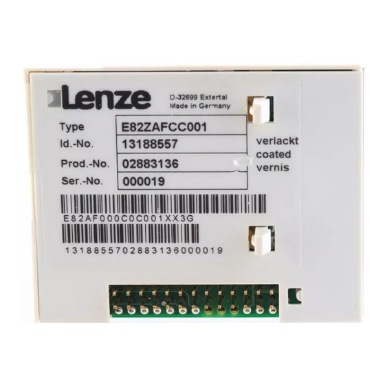
Produktbeschreibung Identifikation Identifikation ‚ƒ ‚ƒ A22 APPLICATION APPLICATION 010 / 3A22 010 / 3A22 Type Id.-No. Prod.-No. Ser.-No. E82AF000P0B201XX E82ZAFX005 ‚ ƒ E82ZAF Gerätereihe Gerätegeneration Variante 001: Verlackte Ausführung Hardwarestand Softwarestand EDK82ZAFCC−001 DE/EN/FR 5.0... -
Page 14: Technische Daten
Lagerung IEC/EN 60721−3−1 1K3 (−25 ... +60 °C) Transport IEC/EN 60721−3−2 2K3 (−25 ... +70 °C) Betrieb Entsprechend der Daten des verwendeten Lenze Grundgerätes (siehe Dokumentation des Grundgerätes). Verschmutzung EN 61800−5−1 Verschmutzungsgrad 2 Daten der Anschlussklemmen Klemme X3/ Eingangswiderstand: 3.3 k Externe Versorgung: U(ext) = 12 V DC −... -
Page 15: Schutzisolierung
Technische Daten Schutzisolierung Schutzisolierung Isolierung zwischen Bus und ... Art der Isolierung (nach EN 61800−5−1) Leistungsteil – 8200 vector Verstärkte Isolierung – 8200 motec Verstärkte Isolierung Betriebsisolierung Bezugserde / PE (X3/7) keine Potentialtrennung Versorgung für CINH (X3/20) Betriebsisolierung Reglersperre, CINH (X3/28) Abmessungen E82ZAFC000B alle Maße in mm... -
Page 16: Mechanische Installation
Mechanische Installation Mechanische Installation Folgen Sie zur mechanischen Installation des Funktionsmoduls den Hinweisen in der Mon- tageanleitung des Grundgerätes. Die Montageanleitung des Grundgerätes ... ƒ ist Teil des Lieferumfangs und liegt jedem Gerät bei. ƒ gibt Hinweise, um Beschädigungen durch unsachgemäße Behandlung zu vermeiden. ƒ... -
Page 17: Elektrische Installation
Elektrische Installation EMV−gerechte Verdrahtung Elektrische Installation EMV−gerechte Verdrahtung Für eine EMV−gerechte Verdrahtung beachten Sie folgende Punkte: Hinweis! Steuer−/Datenleitungen getrennt von Motorleitungen verlegen. ƒ Legen Sie die Schirme der Steuer−/Datenleitungen bei digitalen Signalen ƒ beidseitig auf. Zur Vermeidung von Potenzialdifferenzen zwischen den ƒ... -
Page 18: Verdrahtung Mit Einem Leitrechner
Elektrische Installation Verdrahtung mit einem Leitrechner Verdrahtung mit einem Leitrechner 8200 vector 8200 vector SPS/PC E82ZAFCCxxx E82ZAFCCxxx E82ZAFC013 Abb. 1 Prinzipieller Aufbau Spezifikation des Übertragungskabels Wir empfehlen CAN−Kabel nach ISO 11898−2 zu verwenden: CAN−Kabel nach ISO 11898−2 Kabeltyp Paarverseilt mit Abschirmung Impedanz (95 ... -
Page 19: Daten Der Anschlussklemmen
Elektrische Installation Daten der Anschlussklemmen Daten der Anschlussklemmen Bereich Werte Elektrischer Anschluss Klemmenleiste mit Schraubanschluss Anschlussmöglichkeiten starr: 1.5 mm (AWG 16) flexibel: ohne Aderendhülse 1.0 mm (AWG 18) mit Aderendhülse, ohne Kunststoffhülse 0.5 mm (AWG 20) mit Aderendhülse, mit Kunststoffhülse 0.5 mm (AWG 20) Anzugsmoment... -
Page 20: Belegung Der Anschlussklemmen
Elektrische Installation Belegung der Anschlussklemmen Belegung der Anschlussklemmen Versorgung der Reglersperre (CINH) über die interne Spannungsquelle (X3/20) +20V GND2 GND1 39 28 39 28 7 LO HI 7 LO HI 7 20 20 CAN-GND CAN-LOW CAN-HIGH E82ZAFC035 Versorgung der Reglersperre (CINH) über die externe Spannungsquelle +20V GND2 GND1... - Page 21 Elektrische Installation Belegung der Anschlussklemmen Bezeichnung Funktion Pegel GND2 Bezugspotenzial 2 (nur für X3/28) CINH Reglersperre Start = HIGH (12 ... 30 V) Stop = LOW (0 ... 3 V) GND1 Bezugspotenzial 1 CAN−LOW Systembus LOW (Datenleitung) CAN−HIGH Systembus HIGH (Datenleitung) Interne DC−Spannungsquelle zur Ver- 20 V (Bezug: X3/7) sorgung der Reglersperre (CINH)
-
Page 22: Busleitungslänge
Elektrische Installation Busleitungslänge Busleitungslänge Halten Sie die zulässigen Leitungslängen unbedingt ein. 1. Überprüfen Sie die Einhaltung der Gesamt−Leitungslänge in Tab. 1. Durch die Übertragungsrate ist die Gesamt−Leitungslänge festgelegt. Übertragungsrate [kBit/s] Max. Buslänge [m] 3900 1500 Tab. 1 Gesamt−Leitungslänge 2. Überprüfen Sie die Einhaltung der Segment−Leitungslänge in Tab. 2. Die Segment−Leitungslänge wird durch den verwendeten Leitungsquerschnitt und die Teil- nehmeranzahl festgelegt. - Page 23 Beispiel: Auswahlhilfe Vorgaben (gemäß Kabel−Spezifikation ^ 18) 0.5 mm Leitungsquerschnitt: Teilnehmeranzahl: Lenze−Repeater, Typ 2176 (Leitungsreduzierung: 30 m) Repeater: Bei max. Teilnehmeranzahl (63) sind aus den Vorgaben folgende Leitungslängen / Anzahl Repeater einzuhalten: Übertragungsrate [kBit/s] Max. Leitungslänge [m] 3900 1500 Segment−Leitungslänge [m]...
- Page 24 Ohne Repeater−Einsatz ist die zu realisierende Leitungslänge von 450 m nicht möglich. Es muss ein Repeater nach 360 m (Pkt. 2.) eingesetzt werden. Ergebnis Verwendet wird der Lenze−Repeater, Typ 2176 (Leitungsreduzierung: 30 m) Berechnung der max. Leitungslänge: Erste Segment: 360 m Zweite Segment: 360 m (entsprechend Tab.
-
Page 25: Inbetriebnahme
Inbetriebnahme Vor dem ersten Einschalten Inbetriebnahme Vor dem ersten Einschalten Stop! Bevor Sie das Grundgerät mit Funktionsmodul erstmalig im Systembus−Netzwerk CAN einschalten, überprüfen Sie die gesamte Verdrahtung auf Vollständigkeit, Kurzschluss und Erdschluss. ƒ ob das Bussystem beim physikalisch ersten und letzten Busteilnehmer ƒ... -
Page 26: Erstes Einschalten
Hinweis! Mit der Codestelle C0356/x sind die Zeiten für das zyklische Senden ƒ einstellbar. Die im Antriebsregler gespeicherten Lenze−Codestellen sind vom ƒ CAN−Master über den Index erreichbar. Index = 24575 ˘ Lenze−Codestellennummer (Cxxxx) Das Grundgerät ist nur funktionsfähig, wenn ein HIGH−Pegel an der ƒ... - Page 27 Schritt Beschreibung A Knotenadresse einstellen über ... – C0350 oder – DIP−Schalter (wenn vorhanden). (Lenze−Einstellung: 500 kBit/s) Jede Knotenadresse in einem CAN−Netzwerk darf nur einmal verwendet werden. Übertragungsrate einstellen über ... – C0351 oder – DIP−Schalter (wenn vorhanden). (Lenze−Einstellung: 1) Die Übertragungsrate muss bei allen CAN−Teilnehmern identisch eingestellt...
-
Page 28: Basisidentifier Der Can−Objekte
Inbetriebnahme Basisidentifier der CAN−Objekte Basisidentifier der CAN−Objekte Das CAN−Bussystem ist nachrichtenorientiert und nicht teilnehmerorientiert. Jede Nach- richt hat eine eindeutige Kennung, den Identifier. Bei CANopen wird eine Teilnehmerorien- tierung dadurch erreicht, dass es für jede Nachricht nur einen Sender gibt. Mit Ausnahme des Netzwerkmanagements und des Sync−Telegramms enthält der Identi- fier die Knotenadresse des Antriebs: Identifier (COB−ID) = Basis−Identifier + einstellbare Knotenadresse (Node−ID) - Page 29 Inbetriebnahme Basisidentifier der CAN−Objekte EDK82ZAFCC−001 DE/EN/FR 5.0...
- Page 30 Legend for fold−out page Pos. Description Detailed information Terminal strip X3, terminal for ^ 47 system bus (CAN) voltage supply of the controller inhibit (CINH) ^ 39 Nameplate 0Fig. 0Tab. 0 EDK82ZAFCC−001 DE/EN/FR 5.0...
- Page 31 Contents About this documentation ......... . . Conventions used .
-
Page 32: About This Documentation
This documentation includes ... ƒ Safety instructions which you must observe in any case; ƒ Data about the versions of Lenze standard devices to be used; ƒ Information about the mechanical and electrical installation of the function module; ƒ Information about the commissioning of the function module;... -
Page 33: Conventions Used
About this documentation Conventions used Conventions used This documentation uses the following conventions to distinguish between different types of information: Type of information Identification Examples/notes Numbers Decimal separator Point The decimal point is used throughout this documentation. Example: 1234.56 Symbols Page reference Reference to another page with additional information... -
Page 34: Notes Used
About this documentation Notes used Notes used The following pictographs and signal words are used in this documentation to indicate dangers and important information: Safety instructions Structure of safety instructions: Danger! (characterises the type and severity of danger) Note (describes the danger and gives information about how to prevent dangerous situations) Pictograph and signal word Meaning... - Page 35 About this documentation Notes used Application notes Pictograph and signal word Meaning Important note to ensure troublefree operation Note! Useful tip for simple handling Tip! Reference to another documentation EDK82ZAFCC−001 DE/EN/FR 5.0...
-
Page 36: Safety Instructions
Safety instructions Safety instructions Danger! Inappropriate handling of the function module and the standard device can cause serious injuries to persons and damage to material assets. Observe the safety instructions and residual hazards included in the documentation of the standard device. Stop! Electrostatic discharge Electronic components within the function module can be damaged or... -
Page 37: Product Description
The function module ... ƒ connects the Lenze frequency inverter to the CAN communication system. ƒ is a device to be used in industrial power systems. ƒ is an accessory module which can be used with the following Lenze frequency inverters: Device type... -
Page 38: Scope Of Supply
Product description Scope of supply Scope of supply E82ZAFC004 Pos. Scope of supply E82ZAFCC001 function module Mounting Instructions Screwdriver Two bus terminating resistors (120 each) Adhesive tape EDK82ZAFCC−001 DE/EN/FR 5.0... -
Page 39: Identification
Product description Identification Identification ‚ƒ ‚ƒ A22 APPLICATION APPLICATION 010 / 3A22 010 / 3A22 Type Id.-No. Prod.-No. Ser.-No. E82AF000P0B201XX E82ZAFX005 ‚ ƒ E82ZAF Series Generation Variant 001: Coated design Hardware version Software version EDK82ZAFCC−001 DE/EN/FR 5.0... -
Page 40: Technical Data
IEC/EN 60721−3−1 1K3 (−25 to +60 °C) Transport IEC/EN 60721−3−2 2K3 (−25 to +70 °C) Operation Corresponding to the data of the Lenze standard device used (see documentation of the standard device). Pollution EN 61800−5−1 Degree of pollution 2 Connection terminals Terminal X3/ Input resistance: 3.3 k... -
Page 41: Protective Insulation
Technical data Protective insulation Protective insulation Insulation between bus and ... Type of insulation (in accordance with EN 61800−5−1) Power section – 8200 vector Reinforced insulation – 8200 motec Reinforced insulation Functional insulation Reference earth / PE (X3/7) No electrical isolation Supply for CINH (X3/20) Functional insulation Controller inhibit, CINH (X3/28) -
Page 42: Mechanical Installation
Mechanical installation Mechanical installation Follow the notes given in the Mounting Instructions for the standard device for the mechanical installation of the function module. The Mounting Instructions for the standard device ... ƒ are part of the scope of supply and are enclosed with each device. ƒ... -
Page 43: Electrical Installation
Electrical installation Wiring according to EMC Electrical installation Wiring according to EMC For wiring according to EMC requirements observe the following points: Note! Separate control cables/data lines from motor cables. ƒ Connect the shields of control cables/data lines at both ends in the case of ƒ... -
Page 44: Wiring To A Host
Electrical installation Wiring to a host Wiring to a host 8200 vector 8200 vector SPS/PC E82ZAFCCxxx E82ZAFCCxxx E82ZAFC013 Fig. 1 Basic structure Specification of the transmission cable We recommend the use of CAN cables in accordance with ISO 11898−2: CAN cable in accordance with ISO 11898−2 Cable type Paired with shielding Impedance... -
Page 45: Connection Terminals
Electrical installation Connection terminals Connection terminals Range Values Electrical connection Terminal strip with screw connection Possible connections rigid: 1.5 mm (AWG 16) flexible: without wire end ferrule 1.0 mm (AWG 18) with wire end ferrule, without plastic sleeve 0.5 mm (AWG 20) with wire end ferrule, with plastic sleeve 0.5 mm... -
Page 46: Assignment Of The Terminals
Electrical installation Assignment of the terminals Assignment of the terminals Controller inhibit (CINH) supply via the internal voltage source (X3/20) +20V GND2 GND1 39 28 39 28 7 LO HI 7 LO HI 7 20 20 CAN-GND CAN-LOW CAN-HIGH E82ZAFC035 Controller inhibit (CINH) supply via the external voltage source +20V GND2... - Page 47 Electrical installation Assignment of the terminals Designation Function Level GND2 Reference potential 2 (only for X3/28) CINH Controller inhibit Start = HIGH (12 ... 30 V) Stop = LOW (0 ... 3 V) GND1 Reference potential 1 CAN−LOW System bus LOW (data line) CAN−HIGH System bus HIGH (data line) Internal DC voltage source for supply of...
-
Page 48: Bus Cable Length
Electrical installation Bus cable length Bus cable length It is absolutely necessary to comply with the permissible cable lengths. 1. Check the compliance with the total cable length in Tab. 1. The total cable length is defined by the baud rate. Baud rate [kbps] Max. - Page 49 (according to cable specification ^ 44) 0.5 mm Cable cross−section: Number of nodes: Lenze repeater, type 2176 (cable reduction: 30 m) Repeater: At maximum number of nodes (63) the following cable lengths/number of repeaters must be complied with: Baud rate [kbps] Max.
- Page 50 It is not possible to use a cable length of 450 m without a repeater. After 360 m (item 2.), a repeater must be installed. Result The Lenze repeater type 2176 is used (cable reduction: 30 m) Calculation of the maximum cable length: First segment: 360 m Second segment: 360 m (according to Tab.
-
Page 51: Commissioning
Commissioning Before switching on Commissioning Before switching on Stop! Please check the following before you switch on the controller together with the function module connected to the CAN system bus network: Completeness of the wiring, earth fault and short circuit. ƒ... -
Page 52: Initial Switch−On
Initial switch−on Note! Code C0356/x serves to set the times for cyclic transmission. ƒ The CAN master can access the Lenze codes saved to the controller via the ƒ index. Index = 24575 ˘ Lenze code number (Cxxxx) The controller is only ready for operation if a HIGH level is applied to ƒ... - Page 53 Transmit the setpoint via the selected CAN word (e.g. CAN−IN1.W2). Transmit sync telegram. The sync telegram is only received by the CAN node if C0360 = 1. Lenze setting: sync control Enable standard device via terminal 28 (CINH). Set terminal 28 to HIGH level.
-
Page 54: Basic Identifiers Of The Can Objects
Commissioning Basic identifiers of the CAN objects Basic identifiers of the CAN objects The CAN bus system is message−oriented. Each message has an unambiguous identifier. With CANopen, there is only one sender for each message for device−orientation. Except for the network management and the sync telegram, the identifier contains the node address of the controller: Identifier (COB−ID) = basic identifier + adjustable node address (node ID) The identifier assignment is specified in the CANopen protocol. - Page 55 Commissioning Basic identifiers of the CAN objects EDK82ZAFCC−001 DE/EN/FR 5.0...
- Page 56 Légende de l’illustration de la page dépliante Pos. Description Informations détaillées Bornier X3, pour raccordement ^ 73 du Bus Système CAN, de l’alimentation de la borne de blocage variateur (CINH) ^ 65 Plaque signalétique 0Fig. 0Tab. 0 EDK82ZAFCC−001 DE/EN/FR 5.0...
- Page 57 Sommaire Présentation du document ......... . . Conventions utilisées .
-
Page 58: Présentation Du Document
La présente documentation contient ... ƒ des consignes de sécurité à respecter impérativement ; ƒ les valeurs indiquées concernant les versions des appareils de base Lenze à utiliser ; ƒ des informations sur l’installation mécanique et électrique du module de fonction ;... -
Page 59: Conventions Utilisées
Présentation du document Conventions utilisées Conventions utilisées Pour faire la distinction entre différents types d’informations, ce document utilise les conventions suivantes : Type d’information Marquage Exemples/remarques Représentation des chiffres Séparateur décimal Point Le point décimal est généralement utilisé. Exemple : 1234.56 Symboles Renvoi à... -
Page 60: Consignes Utilisées
Présentation du document Consignes utilisées Consignes utilisées Pour indiquer des risques et des informations importantes, la présente documentation utilise les mots et symboles suivants : Consignes de sécurité Présentation des consignes de sécurité Danger ! (Le pictogramme indique le type de risque.) Explication (L’explication décrit le risque et les moyens de l’éviter.) Pictogramme et mot associé... -
Page 61: Remarque Importante
Présentation du document Consignes utilisées Consignes d’utilisation Pictogramme et mot associé Explication Remarque Remarque importante pour assurer un fonctionnement correct importante ! Conseil utile pour faciliter la mise en oeuvre Conseil ! Référence à une autre documentation EDK82ZAFCC−001 DE/EN/FR 5.0... -
Page 62: Consignes De Sécurité
Consignes de sécurité Consignes de sécurité Danger ! Toute utilisation contre−indiquée du module de fonction et de l’appareil de base peut entraîner des blessures graves et des dommages matériels. Tenir compte des consignes de sécurité et des dangers résiduels énoncés dans la documentation de l’appareil de base. -
Page 63: Description Du Produit
Description du produit Utilisation conforme à la fonction Le module de fonction ... ƒ permet de relier le convertisseur de fréquence Lenze au système de communication CAN. ƒ est un matériel d’exploitation destiné à être utilisé dans les installations industrielles à... -
Page 64: Equipement Livré
Description du produit Equipement livré Equipement livré E82ZAFC004 Pos. Equipement livré Module de fonction E82ZAFCC001 Instructions de montage Tournevis Résistances d’extrémité de bus (de 120 chacune) Bande autocollante EDK82ZAFCC−001 DE/EN/FR 5.0... -
Page 65: Identification
Description du produit Identification Identification ‚ƒ ‚ƒ A22 APPLICATION APPLICATION 010 / 3A22 010 / 3A22 Type Id.-No. Prod.-No. Ser.-No. E82AF000P0B201XX E82ZAFX005 ‚ ƒ E82ZAF Série d’appareils Génération d’appareils Variante 001 : version enduite Version matérielle Version logicielle EDK82ZAFCC−001 DE/EN/FR 5.0... -
Page 66: Spécifications Techniques
CEI/EN 60721−3−1 1K3 (−25 ... +60 °C) Transport CEI/EN 60721−3−2 2K3 (−25 ... +70 °C) Fonctionnement Conformément aux données de l’appareil de base Lenze utilisé (voir la documentation de l’appareil de base). Pollution ambiante EN 61800−5−1 Degré de pollution 2 admissible Spécifications des bornes de raccordement... -
Page 67: Isolement De Protection
Spécifications techniques Isolement de protection Isolement de protection Isolement entre bus et... Type d’isolement (selon EN 61800−5−1) partie puissance – 8200 vector Isolement renforcé – 8200 motec Isolement renforcé Isolement fonctionnel point de terre / PE (X3/7) Sans séparation du potentiel alimentation pour CINH (X3/20) Isolement fonctionnel borne de blocage variateur, CINH (X3/28) -
Page 68: Installation Mécanique
Installation mécanique Installation mécanique Pour l’installation mécanique du module de fonction, suivre les consignes fournies dans les instructions de montage de l’appareil de base. Les instructions de montage de l’appareil de base ... ƒ font partie de la livraison standard et sont comprises dans l’emballage. ƒ... -
Page 69: Installation Électrique
Installation électrique Câblage conforme CEM Installation électrique Câblage conforme CEM Pour s’assurer que le câblage est conforme aux exigences à respecter en matière de CEM, vérifier les points suivants : Remarque importante ! Séparer physiquement les câbles de commande/de données des câbles ƒ... -
Page 70: Raccordement À Un Maître
Installation électrique Raccordement à un maître Raccordement à un maître 8200 vector 8200 vector SPS/PC E82ZAFCCxxx E82ZAFCCxxx E82ZAFC013 Fig. 1 Schéma de principe Spécifications pour câble de transmission Il est recommandé d’utiliser des câbles CAN conformes à la norme ISO 11898−2 : Câbles CAN conformes à... -
Page 71: Spécifications Des Bornes De Raccordement
Installation électrique Spécifications des bornes de raccordement Spécifications des bornes de raccordement Plage Valeurs Raccordement électrique Bornier avec fixation par vis Possibilités de Rigide : raccordement 1.5 mm (AWG 16) Flexible : sans embout 1.0 mm (AWG 18) avec embout, sans cosse en plastique 0.5 mm (AWG 20) avec embout, avec cosse en plastique... -
Page 72: Affectation Des Bornes De Raccordement
Installation électrique Affectation des bornes de raccordement Affectation des bornes de raccordement Alimentation de la borne de blocage variateur (CINH) via tension interne (X3/20) +20V GND2 GND1 39 28 39 28 7 LO HI 7 LO HI 7 20 20 CAN-GND CAN-LOW CAN-HIGH... - Page 73 Installation électrique Affectation des bornes de raccordement Désignation Fonction Niveau GND2 Potentiel de référence 2 (uniquement pour X3/28) CINH Blocage variateur Start = HAUT (12 ... 30 V) Stop = BAS (0 ... 3 V) GND1 Potentiel de référence 1 CAN−LOW Bus Système BAS (ligne de données) CAN−HIGH...
-
Page 74: Longueur De Câble Bus
Installation électrique Longueur de câble bus Longueur de câble bus Respecter impérativement les longueurs de câble autorisées ! 1. Vérifier la longueur de câble totale admise dans le Tab. 1. La longueur de câble totale est déterminée par la vitesse de transmission. Vitesse de transmission Longueur de câble bus maxi [m] [kbits/s]... - Page 75 0.5 mm Section de câble : Nombre de participants : répétiteurs Lenze de type 2176 (réd. de la longueur de câble : 30 m) Répétiteurs : Lorsque le nombre max. de participants (63) est atteint, respecter impérativement les longueurs de câble et le nombre de répétiteurs indiqués ci−dessous :...
- Page 76 Au−delà de 360 m (point 2.), il faut utiliser un répétiteur. Résultat Répétiteur utilisé : répétiteur Lenze de type 2176 (réduction de la longueur de câble : 30 m) Calcul de la longueur de câble max. : Premier segment : 360 m Second segment : 360 m (selon Tab.
-
Page 77: Mise En Service
Mise en service Avant la première mise sous tension Mise en service Avant la première mise sous tension Stop ! Avant la première mise sous tension de l’appareil de base avec le module de fonction raccordé au Bus Système CAN, vérifier le câblage dans son intégralité... -
Page 78: Première Mise En Service
Le code C0356/x permet de régler les temps relatifs aux émissions ƒ cycliques. Les codes Lenze sauvegardés sur le variateur peuvent être consultés par le ƒ maître CAN via l’index correspondant. Index = 24575 ˘ Numéro de code Lenze (Cxxxx) L’appareil de base ne peut fonctionner que si la borne 28 est sur niveau... - Page 79 Envoyer le télégramme Sync. Le télégramme Sync est réceptionné par le participant au bus CAN si C0360 = 1. Réglage Lenze : commande par Sync Débloquer l’appareil de base via la borne 28 (CINH). Activer le niveau HAUT sur la borne 28.
-
Page 80: Identificateur De Base Des Objets Can
Mise en service Identificateur de base des objets CAN Identificateur de base des objets CAN Le Bus Système CAN est orienté message et non participant. Chaque message est identifié par un identificateur. Avec CANopen, l’orientation participant découle du fait qu’à chaque message correspond un seul émetteur. - Page 81 Mise en service Identificateur de base des objets CAN EDK82ZAFCC−001 DE/EN/FR 5.0...
- Page 82 © 06/2010 Lenze Drives GmbH Service Lenze Service GmbH Postfach 10 13 52 Breslauer Straße 3 D−31763 Hameln D−32699 Extertal Germany Germany +49 (0)51 54 / 82−0 00 80 00 / 24 4 68 77 (24 h helpline) Ê Ê...