Publicité

Les langues disponibles

Les langues disponibles

Liens rapides

EDK82ZAFSC
.=#y
STANDARD−I/O
E82ZAFSC / E82ZAFSC001
Funktionsmodul
Function module
Module de fonction
Montageanleitung
Mounting Instructions
Instructions de montage
l

Publicité

Table des Matières
loading

Sommaire des Matières pour Lenze E82ZAFSC

  • Page 1 EDK82ZAFSC .=#y Montageanleitung Mounting Instructions Instructions de montage STANDARD−I/O E82ZAFSC / E82ZAFSC001 Funktionsmodul Function module Module de fonction...
  • Page 2 Lesen Sie zuerst diese Anleitung und die Dokumentation zum Grundgerät, bevor Sie mit den Arbeiten beginnen! Beachten Sie die enthaltenen Sicherheitshinweise. Please read these instructions and the documentation of the standard device before you start working! Observe the safety instructions given therein! Lire le présent fascicule et la documentation relative à...
  • Page 3 E82ZAFS002A...
  • Page 4 Legende zur Abbildung auf der Ausklappseite Pos. Beschreibung Ausführliche Information Funktionsmodul E82ZAFSC / E82ZAFSC001 ^ 21 Schalter zur Konfigurierung des Analogeingangs (Klemme X3/8) ^ 19 Digitale und analoge Ein− und Ausgänge, Klemmenleiste X3 ^ 12 Typenschild 0Abb. 0Tab. 0 EDK82ZAFSC DE/EN/FR 5.0...
  • Page 5: Table Des Matières

    Inhalt Über diese Dokumentation ......... . Verwendete Konventionen .
  • Page 6: Über Diese Dokumentation

    ƒ Informationen zur mechanischen und elektrischen Installation des Funktionsmoduls; ƒ Informationen zur Inbetriebnahme des Funktionsmoduls; ƒ Sicherheitshinweise, die Sie unbedingt beachten müssen; ƒ Angaben über Versionsstände der zu verwendenden Lenze Grundgeräte; ƒ Technische Daten. Informationen zur Gültigkeit Die Informationen in dieser Dokumentation sind gültig für folgende Geräte:...
  • Page 7: Verwendete Konventionen

    Über diese Dokumentation Verwendete Konventionen Verwendete Konventionen Diese Dokumentation verwendet folgende Konventionen zur Unterscheidung verschiede- ner Arten von Information: Informationsart Auszeichnung Beispiele/Hinweise Zahlenschreibweise Dezimaltrennzeichen Punkt Es wird generell der Dezimalpunkt verwendet. Beispiel: 1234.56 Symbole Seitenverweis Verweis auf eine andere Seite mit zu- sätzlichen Informationen Beispiel: 16 = siehe Seite 16...
  • Page 8: Verwendete Hinweise

    Über diese Dokumentation Verwendete Hinweise Verwendete Hinweise Um auf Gefahren und wichtige Informationen hinzuweisen, werden in dieser Dokumenta- tion folgende Piktogramme und Signalwörter verwendet: Sicherheitshinweise Aufbau der Sicherheitshinweise: Gefahr! (kennzeichnet die Art und die Schwere der Gefahr) Hinweistext (beschreibt die Gefahr und gibt Hinweise, wie sie vermieden werden kann) Piktogramm und Signalwort Bedeutung Gefahr von Personenschäden durch gefährliche elektrische...
  • Page 9: Sicherheitshinweise

    Sicherheitshinweise Sicherheitshinweise Gefahr! Unsachgemäßer Umgang mit dem Funktionsmodul und dem Grundgerät kann schwere Personenschäden und Sachschäden verursachen. Beachten Sie die in der Dokumentation zum Grundgerät enthaltenen Sicherheitshinweise und Restgefahren. Stop! Elektrostatische Entladung Durch elektrostatische Entladung können elektronische Bauteile innerhalb des Funkionsmoduls beschädigt oder zerstört werden.
  • Page 10: Produktbeschreibung

    Produktbeschreibung Funktion Produktbeschreibung Funktion Das Funktionsmodul ermöglicht das Ansteuern von Lenze Frequenzumrichtern und der Lenze Antriebs−SPS mit analogen und digitalen Steuersignalen. Bestimmungsgemäße Verwendung Das Funktionsmodul ... ƒ ist eine Zubehör−Baugruppe, die mit folgenden Lenze Grundgeräten eingesetzt werden kann: Funktionsmodul Lenze Grundgeräte Produktreihe Gerätebezeichnung...
  • Page 11: Lieferumfang

    Produktbeschreibung Lieferumfang Lieferumfang E82ZAFS002A / E82ZAFX019 Pos. Lieferumfang Funktionsmodul E82ZAFSC / E82ZAFSC001 Schraubendreher Aufkleber Montageanleitung EDK82ZAFSC DE/EN/FR 5.0...
  • Page 12: Identifikation

    Produktbeschreibung Identifikation Identifikation ‚ƒ  ‚ƒ A22 APPLICATION APPLICATION 010 / 3A22 010 / 3A22 Type Id.-No. Prod.-No. Ser.-No. E82AF000P0B201XX E82ZAFX005  ‚ ƒ E82ZAF Produktreihe STANDARD−I/O Gerätegeneration Variante 000: Standard 001: verlackte Leiterplatten Hardwarestand EDK82ZAFSC DE/EN/FR 5.0...
  • Page 13: Technische Daten

    Wahlweise Frequenzeingang 0 … 10 kHz einspurig oder 0 ... 1 kHz zweispurig, Konfig. über C0425 Einsatzbedingungen Umgebungsbedingungen Klimatisch Lagerung IEC/EN 60721−3−1 1K3 (−25 ... +60 °C) Transport IEC/EN 60721−3−2 2K3 (−25 ... +70 °C) Betrieb Entsprechend der Daten des verwendeten Lenze Grundgerätes (siehe Dokumentation des Grundgerätes). Verschmutzung EN 61800−5−1 Verschmutzungsgrad 2 EDK82ZAFSC DE/EN/FR 5.0...
  • Page 14: Abmessungen

    Technische Daten Abmessungen Abmessungen E82ZAFS002A alle Maße in mm EDK82ZAFSC DE/EN/FR 5.0...
  • Page 15: Mechanische Installation

    Mechanische Installation Mechanische Installation Folgen Sie zur mechanischen Installation des Funktionsmoduls den Hinweisen in der Mon- tageanleitung des Grundgerätes. Die Montageanleitung des Grundgerätes ... ƒ ist Teil des Lieferumfangs und liegt jedem Gerät bei. ƒ gibt Hinweise, um Beschädigungen durch unsachgemäße Behandlung zu vermeiden. ƒ...
  • Page 16: Elektrische Installation

    Elektrische Installation EMV−gerechte Verdrahtung Elektrische Installation EMV−gerechte Verdrahtung Für eine EMV−gerechte Verdrahtung beachten Sie folgende Punkte: Hinweis! Steuerleitungen getrennt von Motorleitungen verlegen. ƒ Schirme so weit wie möglich an die Klemmen führen (ungeschirmte ƒ Aderlänge < 40 mm). Legen Sie die Schirme der Steuerleitungen bzw. Datenleitungen wie folgt ƒ...
  • Page 17: Verdrahtung

    Elektrische Installation Verdrahtung Verdrahtung Daten der Anschlussklemmen Bereich Werte Elektrischer Anschluss Klemmenleiste mit Schraubanschluss Anschlussmöglichkeiten starr: 1.5 mm (AWG 16) flexibel: ohne Aderendhülse 1.0 mm (AWG 18) mit Aderendhülse, ohne Kunststoffhülse 0.5 mm (AWG 20) mit Aderendhülse, mit Kunststoffhülse 0.5 mm (AWG 20) Anzugsmoment 0.22 ...
  • Page 18 Elektrische Installation Verdrahtung Versorgung über die interne Spannungsquelle (X3/20): ƒ X3/28, Reglersperre (CINH) ƒ X3/E1 ..X3/E4, digitale Eingänge GND2 GND1 GND1 +20V 20 28 E1 E2 E3 E4 39 A1 59 AOUT1 AIN1 DIGOUT1 1k … 10k E82ZAFS004 Versorgung über eine externe Spannungsquelle: ƒ...
  • Page 19 Offset (C0026) und Verstärkung (C0027) für jedes Funktionsmodul separat abgleichen ... − nach Austausch des Funktionsmoduls oder des Grundgerätes. − nach Laden der Lenze−Einstellung. Wahlweise Frequenzeingang 0 … 10 kHz einspurig oder 0 ... 1 kHz zweispurig, Konfig. über C0425...
  • Page 20: Inbetriebnahme

    Inbetriebnahme Vor dem ersten Einschalten Inbetriebnahme Vor dem ersten Einschalten Hinweis! Wenn Sie die Inbetriebnahme mit einer von der Lenze−Einstellung ƒ abweichenden Konfiguration durchführen, lesen Sie die Anweisungen "Individuelle Einstellungen" (^ 22). Achten Sie darauf, ƒ – dass Sie mit dem DIP−Schalter am Funktionsmodul den Sollwertbereich richtig eingestellt haben (^ 21).
  • Page 21: Dip−Schalterstellung

    Drehzahlbereich durchfahren werden. Signal an X3/8 C0034 Schalterstellung 0 ... 5 V 0 ... 10 V (Lenze−Einstellung) 0 ... 20 mA 4 ... 20 mA 4 ... 20 mA (drahtbruchüberwacht) −10 ... +10 V EDK82ZAFSC DE/EN/FR 5.0...
  • Page 22: Inbetriebnahmeschritte

    Das Grundgerät ist nach ca. 1 Sekunde betriebsbereit. Die Reglersperre ist aktiv. Reaktion des Grundgerätes: Die grüne LED blinkt. Keypad: (falls aufgesteckt) Digitale Eingänge ansteu- Lenze−Einstellung: ern. Rechtslauf: – E1, E2, E3, E4: LOW Linkslauf: – E1, E2, E3: LOW – E4: HIGH Individuelle Einstellung: Digitale Eingänge über C0007 oder C0410 anpassen.
  • Page 23 Inbetriebnahme Inbetriebnahmeschritte Hinweis! Das Grundgerät ist nur funktionsfähig, wenn ein HIGH−Pegel an X3/28 anliegt (Reglerfreigabe über Klemme). Beachten Sie, dass die Reglersperre über mehrere Quellen gesetzt werden ƒ kann. Die Quellen wirken wie eine Reihenschaltung von Schaltern. Wenn der Antrieb trotz Reglerfreigabe über X3/28 nicht anläuft, ƒ...
  • Page 24 Legend for fold−out page Pos. Description Detailed information Function module E82ZAFSC / E82ZAFSC001 ^ 41 Switch for the configuration of the analog input (terminal X3/8) ^ 39 Digital and analog inputs and outputs, terminal strip X3 ^ 32 Nameplate 0Fig. 0Tab. 0...
  • Page 25 Contents About this documentation ......... . . Conventions used .
  • Page 26: About This Documentation

    ƒ Information about the mechanical and electrical installation of the function module; ƒ Information about the commissioning of the function module; ƒ Safety instructions which you must observe in any case; ƒ Data about the versions of Lenze basic devices to be used; ƒ Technical data. Validity information...
  • Page 27: Conventions Used

    About this documentation Conventions used Conventions used This documentation uses the following conventions to distinguish between different types of information: Type of information Identification Examples/notes Numbers Decimal separator Point The decimal point is used throughout this documentation. Example: 1234.56 Symbols Page reference Reference to another page with additional information...
  • Page 28: Notes Used

    About this documentation Notes used Notes used The following pictographs and signal words are used in this documentation to indicate dangers and important information: Safety instructions Structure of safety instructions: Danger! (characterises the type and severity of danger) Note (describes the danger and gives information about how to prevent dangerous situations) Pictograph and signal word Meaning...
  • Page 29: Safety Instructions

    Safety instructions Safety instructions Danger! Inappropriate handling of the function module and the basic device can cause serious injuries to persons and damage to material assets. Observe the safety instructions and residual hazards included in the documentation of the basic device. Stop! Electrostatic discharge Electronic components within the function module can be damaged or...
  • Page 30: Product Description

    The function module allows the control of Lenze frequency inverters and the Lenze Drive PLC with analog and digital control signals. Application as directed The function module ... ƒ is an accessories unit which can be used with the following Lenze basic devices: Function module Lenze basic devices Product range...
  • Page 31: Scope Of Supply

    Product description Scope of supply Scope of supply E82ZAFS002A / E82ZAFX019 Pos. Scope of supply Function module E82ZAFSC / E82ZAFSC001 Screw driver Sticker Mounting Instructions EDK82ZAFSC DE/EN/FR 5.0...
  • Page 32: Identification

    Product description Identification Identification ‚ƒ  ‚ƒ A22 APPLICATION APPLICATION 010 / 3A22 010 / 3A22 Type Id.-No. Prod.-No. Ser.-No. E82AF000P0B201XX E82ZAFX005  ‚ ƒ E82ZAF Product range STANDARD I/O Generation Variant 000: standard 001: coated PCBs Hardware version EDK82ZAFSC DE/EN/FR 5.0...
  • Page 33: Technical Data

    1K3 (−25 to +60 °C) Transport IEC/EN 60721−3−2 2K3 (−25 to +70 °C) Operation Corresponding to the data of the Lenze basic device used (see documentation of the basic device). Pollution EN 61800−5−1 Degree of pollution 2 EDK82ZAFSC DE/EN/FR 5.0...
  • Page 34: Dimensions

    Technical data Dimensions Dimensions E82ZAFS002A All dimensions in mm EDK82ZAFSC DE/EN/FR 5.0...
  • Page 35: Mechanical Installation

    Mechanical installation Mechanical installation Follow the notes given in the Mounting Instructions for the standard device for the mechanical installation of the function module. The Mounting Instructions for the standard device ... ƒ are part of the scope of supply and are enclosed with each device. ƒ...
  • Page 36: Electrical Installation

    Electrical installation Wiring according to EMC Electrical installation Wiring according to EMC Please observe the following for wiring according to EMC guidelines: Note! Separate control cables from motor cables. ƒ Lead the shields as far as possible to the terminals (unshielded core length ƒ...
  • Page 37: Wiring

    Electrical installation Wiring Wiring Terminal data Range Values Electrical connection Terminal strip with screw connection Possible connections rigid: 1.5 mm (AWG 16) flexible: without wire end ferrule 1.0 mm (AWG 18) with wire end ferrule, without plastic sleeve 0.5 mm (AWG 20) with wire end ferrule, with plastic sleeve 0.5 mm...
  • Page 38 Electrical installation Wiring Supply via the internal voltage source (X3/20): ƒ X3/28, controller inhibit (CINH) ƒ X3/E1 ..X3/E4, digital inputs GND2 GND1 GND1 +20V 20 28 E1 E2 E3 E4 39 A1 59 AOUT1 AIN1 DIGOUT1 1k … 10k E82ZAFS004 Supply via an external voltage source: ƒ...
  • Page 39 Adjust offset (C0026) and gain (C0027) separately for each function module ... − after replacing the function module or the basic device. − after loading the Lenze setting. Frequency input alternatively 0 … 10 kHz single−track or 0 ... 1 kHz two−track, config. via C0425...
  • Page 40: Commissioning

    Note! If you carry out the commissioning with a configuration different from the ƒ Lenze setting, read the instructions on "Individual Settings" (^ 42). Make sure ƒ – that you have correctly set the setpoint range with the DIP switch on the function module (^ 41).
  • Page 41: Dip Switch Position

    Signal at X3/8 C0034 Switch position 0 ... 5V 0 ... 10 V (Lenze setting) 0 ... 20 mA 4 ... 20 mA 4 ... 20 mA (open−circuit monitored) −10 ... +10 V...
  • Page 42: Commissioning Steps

    The controller inhibit is active. Drive response: The green LED is blinking. Keypad: (if attached) Control digital inputs. Lenze setting: CW rotation: – E1, E2, E3, E4: LOW CCW rotation: – E1, E2, E3: LOW – E4: HIGH Individual setting: Adapt digital inputs under C0007 or C0410.
  • Page 43 Commissioning Commissioning steps Note! The basic device is only functioning if a HIGH level is applied to X3/28 (controller release via terminal). Please observe that the controller can be inhibited through various ƒ sources. All sources act like a series connection of switches. If the drive does not start in spite of the controller release via X3/28, check ƒ...
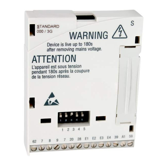
  • Page 44 Légende de l’illustration de la page dépliante Pos. Description Informations détaillées Module de fonction E82ZAFSC / E82ZAFSC001 ^ 62 Interrupteur pour la configuration de l’entrée analogique (borne X3/8) ^ 60 Entrées et sorties numériques et analogiques, bornier X3 ^ 53 Plaque signalétique...
  • Page 45 Sommaire Présentation du document ......... . . Conventions utilisées .
  • Page 46: Présentation Du Document

    ƒ des informations sur la mise en service du module de fonction ; ƒ des consignes de sécurité à respecter impérativement ; ƒ les valeurs indiquées concernant les versions des appareils de base Lenze à utiliser ; ƒ les spécifications techniques.
  • Page 47: Conventions Utilisées

    Présentation du document Conventions utilisées Conventions utilisées Pour faire la distinction entre différents types d’informations, ce document utilise les conventions suivantes : Type d’information Marquage Exemples/remarques Représentation des chiffres Séparateur décimal Point Le point décimal est généralement utilisé. Exemple : 1234.56 Symboles Renvoi à...
  • Page 48: Remarques Utilisées

    Présentation du document Remarques utilisées Remarques utilisées Pour indiquer des risques et des informations importantes, la présente documentation utilise les mots et symboles suivants : Consignes de sécurité Présentation des consignes de sécurité Danger ! (Le pictogramme indique le type de risque.) Explication (L’explication décrit le risque et les moyens de l’éviter.) Pictogramme et mot associé...
  • Page 49 Présentation du document Remarques utilisées Consignes d’utilisation Pictogramme et mot associé Explication Remarque Remarque importante pour assurer un fonctionnement correct importante ! Conseil utile pour faciliter la mise en oeuvre Conseil ! Référence à une autre documentation EDK82ZAFSC DE/EN/FR 5.0...
  • Page 50: Consignes De Sécurité

    Consignes de sécurité Consignes de sécurité Danger ! L’utilisation non conforme à la fonction du module de fonction et de l’appareil de base peut entraîner de graves dommages corporels et matériels. Tenir compte des consignes de sécurité et des dangers résiduels énoncés dans la documentation de l’appareil de base.
  • Page 51: Description Du Produit

    Lenze à l’aide de signaux de commande analogiques et numériques. Utilisation conforme à la fonction Le module de fonction ... ƒ est un pack d’accessoires qui peuvent être utilisés avec les appareils de base Lenze suivants : Module de fonction...
  • Page 52: Equipement Livré

    Description du produit Equipement livré Equipement livré E82ZAFS002A / E82ZAFX019 Pos. Contenu de l’emballage Module de fonction E82ZAFSC / E82ZAFSC001 Tournevis Autocollant Instructions de montage EDK82ZAFSC DE/EN/FR 5.0...
  • Page 53: Identification

    Description du produit Identification Identification ‚ƒ  ‚ƒ A22 APPLICATION APPLICATION 010 / 3A22 010 / 3A22 Type Id.-No. Prod.-No. Ser.-No. E82AF000P0B201XX E82ZAFX005  ‚ ƒ E82ZAF Gamme de produits E/S STANDARD Génération d’appareils Variante 000 : standard 001 : carte de circuit imprimé vernie Version matérielle EDK82ZAFSC DE/EN/FR 5.0...
  • Page 54: Spécifications Techniques

    CEI/EN 60721−3−1 1K3 (−25 ... +60 °C) Transport CEI/EN 60721−3−2 2K3 (−25 ... +70 °C) Fonctionnement Conformément aux données de l’appareil de base Lenze utilisé (voir la documentation de l’appareil de base). Pollution ambiante EN 61800−5−1 Degré de pollution 2 admissible...
  • Page 55: Encombrements

    Spécifications techniques Encombrements Encombrements E82ZAFS002A Toutes les cotes en mm EDK82ZAFSC DE/EN/FR 5.0...
  • Page 56: Installation Mécanique

    Installation mécanique Installation mécanique Pour l’installation mécanique du module de fonction, suivre les consignes fournies dans les instructions de montage de l’appareil de base. Les instructions de montage de l’appareil de base ... ƒ font partie de la livraison standard et sont comprises dans l’emballage. ƒ...
  • Page 57: Installation Électrique

    Installation électrique Câblage conforme CEM Installation électrique Câblage conforme CEM Pour réaliser un câblage conforme CEM, respectez les points suivants : Remarque importante ! Poser les câbles de commande séparément des câbles moteur. ƒ Conduire le blindage aussi loin que possible vers les bornes (longueur de fil ƒ...
  • Page 58: Câblage

    Installation électrique Câblage Câblage Spécifications des bornes de raccordement Plage Valeurs Raccordement électrique Bornier avec fixation par vis Possibilités de raccordement Rigide : 1,5 mm (AWG 16) Flexible : sans embout 1,0 mm (AWG 18) avec embout, sans cosse en plastique 0,5 mm (AWG 20) avec embout, avec cosse en plastique...
  • Page 59 Installation électrique Câblage Alimentation via la source de tension interne (X3/20) : ƒ X3/28, blocage variateur (CINH) ƒ X3/E1 ..X3/E4, entrées numériques GND2 GND1 GND1 +20V 20 28 E1 E2 E3 E4 39 A1 59 AOUT1 AIN1 DIGOUT1 1k … 10k E82ZAFS004 Alimentation via une source de tension externe : ƒ...
  • Page 60 − après le remplacement du module de fonction ou de l’appareil de base. − après le chargement du réglage Lenze. Au choix : entrée de fréquence 0 … 10 kHz à une voie ou 0 ... 1 kHz à deux voies, configuration via C0425...
  • Page 61: Mise En Service

    Remarque importante ! Si vous effectuez la mise en service avec une configuration différente du ƒ réglage Lenze, lisez les instructions "Réglages individuels" (^ 63). Assurez−vous ƒ – que la plage de la consigne est réglée correctement à l’aide de l’interrupteur DIP au niveau du module de fonction(^ 62).
  • Page 62: Position D'interrupteur Dip

    Autrement, la plage de vitesse ne pourra pas être parcourue en entier. Signal sur X3/8 C0034 Position interrupteur 0 ... 5 V 0 ... 10 V (réglage Lenze) 0 à 20 mA 4 à 20 mA 4 ... 20 mA (avec contrôle de rupture de fil) −10 ...
  • Page 63: Etapes De Mise En Service

    Réaction de l’appareil de base : La LED verte clignote. Clavier de commande : (le cas échéant) Activer les entrées Réglage Lenze : numériques. Rotation horaire : – E1, E2, E3, E4 : LOW (BAS) Rotation antihoraire : – E1, E2, E3 : LOW (BAS) –...
  • Page 64 Mise en service Etapes de mise en service Remarque importante ! L’appareil de base ne peut fonctionner que lorsqu’un niveau HAUT est actif sur la borne X3/28 (déblocage variateur via borne). Veillez à ce que le blocage variateur puisse être défini par le biais de ƒ...
  • Page 65 © 12/2008 Lenze Drives GmbH Service Lenze Service GmbH Postfach 10 13 52 Breslauer Straße 3 D−31763 Hameln D−32699 Extertal Germany Germany +49 (0)51 54 / 82−0 00 80 00 / 24 4 68 77 (24 h helpline) Ê Ê...

Ce manuel est également adapté pour:

E82zafsc001Standard-i/o

Table des Matières