
Manuels Connexes pour Lenze LECOM-B E82ZAFLC001


Sommaire des Matières pour Lenze LECOM-B E82ZAFLC001
- Page 1 EDK82ZAFLC−001 L−force Communication .R<H Montageanleitung Mounting Instructions Instructions de montage LECOM−B E82ZAFLC001 Funktionsmodul Function module Module de fonction...
- Page 2 Lesen Sie zuerst diese Anleitung und die Dokumentation zum Grundgerät, bevor Sie mit den Arbeiten beginnen! Beachten Sie die enthaltenen Sicherheitshinweise. Please read these instructions and the documentation of the standard device before you start working! Observe the safety instructions given therein! Lire le présent fascicule et la documentation relative à...
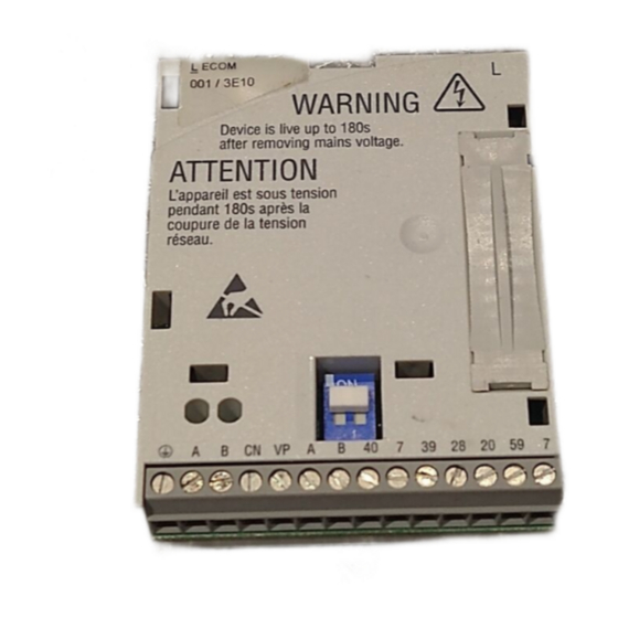
- Page 3 E82ZAFLC011B 0Abb. 0Tab. 0 Pos. Beschreibung Ausführliche Information Funktionsmodul E82ZAFLC001 ^ 24 DIP−Schalter zur Aktivierung des Busabschluss−Widerstandes Statusanzeige (gelb) Kommunikation LECOM−B ^ 28 Statusanzeige (grün) Kommunikation Antrieb Klemmenleiste X3, Anschlüsse für LECOM−B ^ 20 Reglersperre (CINH) externe Spannungsversorgung ^ 12 Typenschild EDK82ZAFLC−001 DE/EN/FR 6.0...
-
Page 4: Table Des Matières
Inhalt Über diese Dokumentation ......... . Verwendete Konventionen . -
Page 5: Über Diese Dokumentation
ƒ Funktionsmodule E82ZAFLC001, LECOM−B, ab Version 3A.10. Zielgruppe Diese Dokumentation richtet sich an Personen, die die Vernetzung und Fernwartung einer Maschine projektieren, installieren, in Betrieb nehmen und warten. Tipp! Informationen und Hilfsmittel rund um die Lenze−Produkte finden Sie im Download−Bereich unter www.lenze.com EDK82ZAFLC−001 DE/EN/FR 6.0... -
Page 6: Verwendete Konventionen
Über diese Dokumentation Verwendete Konventionen Verwendete Konventionen Diese Dokumentation verwendet folgende Konventionen zur Unterscheidung verschiede- ner Arten von Information: Informationsart Auszeichnung Beispiele/Hinweise Zahlenschreibweise Dezimaltrennzeichen Punkt Es wird generell der Dezimalpunkt verwendet. Beispiel: 1234.56 Symbole Seitenverweis Verweis auf eine andere Seite mit zu- sätzlichen Informationen Beispiel: 16 = siehe Seite 16... -
Page 7: Verwendete Hinweise
Über diese Dokumentation Verwendete Hinweise Verwendete Hinweise Um auf Gefahren und wichtige Informationen hinzuweisen, werden in dieser Dokumenta- tion folgende Piktogramme und Signalwörter verwendet: Sicherheitshinweise Aufbau der Sicherheitshinweise: Gefahr! (kennzeichnet die Art und die Schwere der Gefahr) Hinweistext (beschreibt die Gefahr und gibt Hinweise, wie sie vermieden werden kann) Piktogramm und Signalwort Bedeutung Gefahr von Personenschäden durch gefährliche elektri-... - Page 8 Über diese Dokumentation Verwendete Hinweise Anwendungshinweise Piktogramm und Signalwort Bedeutung Wichtiger Hinweis für die störungsfreie Funktion Hinweis! Nützlicher Tipp für die einfache Handhabung Tipp! Verweis auf andere Dokumentation EDK82ZAFLC−001 DE/EN/FR 6.0...
-
Page 9: Sicherheitshinweise
Sicherheitshinweise Sicherheitshinweise Gefahr! Unsachgemäßer Umgang mit dem Funktionsmodul und dem Grundgerät kann schwere Personenschäden und Sachschäden verursachen. Beachten Sie die in der Dokumentation zum Grundgerät enthaltenen Sicherheitshinweise und Restgefahren. Stop! Elektrostatische Entladung Durch elektrostatische Entladung können elektronische Bauteile innerhalb des Funkionsmoduls beschädigt oder zerstört werden. -
Page 10: Produktbeschreibung
Das Funktionsmodul koppelt Lenze−Antriebsregler über den Lenze−Feldbus LECOM−B (RS485) an einen übergeordneten Leitrechner (SPS, PC). Bestimmungsgemäße Verwendung Das Funktionsmodul E82ZAFLC001 ... ƒ ist ein Betriebsmittel zum Einsatz in industriellen Starkstromanlagen; ƒ ist eine Zubehör−Baugruppe, die mit folgenden Lenze Grundgeräten eingesetzt werden kann: Grundgerät ab Version Frequenzumrichter... -
Page 11: Lieferumfang
Produktbeschreibung Lieferumfang Lieferumfang E82ZAFP004/E82ZAFL011B Pos. Lieferumfang Funktionsmodul E82ZAFLC001 Montageanleitung Schraubendreher Klebestreifen Tipp! Weiterführende Informationen zu diesem Funktionsmodul finden Sie im entsprechenden Kommunikationshandbuch. Die PDF−Datei finden Sie im Download−Bereich unter: http://www.Lenze.com EDK82ZAFLC−001 DE/EN/FR 6.0... -
Page 12: Identifikation
Produktbeschreibung Identifikation Identifikation ‚ƒ ‚ƒ A22 APPLICATION APPLICATION 010 / 3A22 010 / 3A22 Type Id.-No. Prod.-No. Ser.-No. E82AF000P0B201XX E82ZAFX005 ‚ ƒ E82ZAF Gerätereihe LECOM−B Gerätegeneration Variante 001: verlackte Ausführung Hardwarestand Softwarestand EDK82ZAFLC−001 DE/EN/FR 6.0... -
Page 13: Technische Daten
Technische Daten Allgemeine Daten und Einsatzbedingungen Technische Daten Allgemeine Daten und Einsatzbedingungen Allgemeine Daten Bereich Werte Kommunikationsprotokoll LECOM−A/B V2.0 Kommunikationsmedium RS485 (LECOM−B) Übertragungszeichenformat 7E1: 7 Bit ASCII, 1 Stopp−Bit, 1 Start−Bit, 1 Paritäts−Bit (gerade) Übertragungsrate [kBit/s] 1200, 2400, 4800, 9600, 19200, 38400, 57600 LECOM−B−Teilnehmer Slave Netzwerk−Topologie... - Page 14 Allgemeine Daten und Einsatzbedingungen Einsatzbedingungen Umgebungsbedingungen Klimatisch Lagerung IEC/EN 60721−3−1 1K3 (−25 ... +60 °C) Transport IEC/EN 60721−3−2 2K3 (−25 ... +70 °C) Betrieb Entsprechend der Daten des verwendeten Lenze Grundgerätes (siehe Dokumentation des Grundgerätes). Verschmutzung EN 61800−5−1 Verschmutzungsgrad 2 EDK82ZAFLC−001 DE/EN/FR 6.0...
-
Page 15: Schutzisolierung
Technische Daten Schutzisolierung Schutzisolierung Isolierung zwischen Bus und ... Art der Isolierung (nach EN61800−5−1) Leistungsteil – 8200 vector Verstärkte Isolierung – 8200 motec Verstärkte Isolierung Bezugserde / PE (X3/7) Betriebsisolierung externe Versorgung (X3/59) Betriebsisolierung Steuerklemmen – X3/20 (interne Versorgung) Betriebsisolierung –... -
Page 16: Abmessungen
Technische Daten Abmessungen Abmessungen E82ZAFL011B alle Maße in mm EDK82ZAFLC−001 DE/EN/FR 6.0... -
Page 17: Mechanische Installation
Mechanische Installation Mechanische Installation Folgen Sie zur mechanischen Installation des Funktionsmoduls den Hinweisen in der Mon- tageanleitung des Grundgerätes. Die Montageanleitung des Grundgerätes ... ƒ ist Teil des Lieferumfangs und liegt jedem Gerät bei. ƒ gibt Hinweise, um Beschädigungen durch unsachgemäße Behandlung zu vermeiden. ƒ... -
Page 18: Elektrische Installation
Elektrische Installation EMV−gerechte Verdrahtung Elektrische Installation EMV−gerechte Verdrahtung Für eine EMV−gerechte Verdrahtung beachten Sie folgende Punkte: Hinweis! Steuer−/Datenleitungen getrennt von Motorleitungen verlegen. ƒ Legen Sie die Schirme der Steuer−/Datenleitungen bei digitalen Signalen ƒ beidseitig auf. Zur Vermeidung von Potenzialdifferenzen zwischen den ƒ... -
Page 19: Daten Der Anschlussklemmen
Elektrische Installation Daten der Anschlussklemmen Daten der Anschlussklemmen Bereich Werte Elektrischer Anschluss Klemmenleiste mit Schraubanschluss Anschlussmöglichkeiten starr: 1.5 mm (AWG 16) flexibel: ohne Aderendhülse 1.0 mm (AWG 18) mit Aderendhülse, ohne Kunststoffhülse 0.5 mm (AWG 20) mit Aderendhülse, mit Kunststoffhülse 0.5 mm (AWG 20) Anzugsmoment... -
Page 20: Spannungsversorgung
Elektrische Installation Spannungsversorgung Spannungsversorgung Hinweis! Verwenden Sie bei externer Spannungsversorgung und bei größeren Entfernungen zwischen den Schaltschränken in jedem Schaltschrank immer ein separates und nach EN 61800−5−1 sicher getrenntes Netzteil (SELV/PELV). DC−Spannungsversorgung Intern Die interne Spannung steht an Klemme X3.3/20 zur Verfügung. Sie dient der Versor- gung der Reglersperre (CINH). - Page 21 Elektrische Installation Spannungsversorgung Versorgung der Reglersperre (CINH) über die interne Spannungsquelle (X3/20) GND1 GND1 GND2 GND3 +20V B CN 20 59 T/R(A) T/R(B) T/R(A) T/R(B) E82ZAFP001 Versorgung der Reglersperre (CINH) über die externe Spannungsquelle GND1 GND1 GND3 GND2 +20V B CN 20 59 T/R(A) T/R(B) T/R(A) T/R(B) E82ZAFP002...
-
Page 22: Verdrahtung Des Lecom−B−Netzwerkes
Elektrische Installation Verdrahtung des LECOM−B−Netzwerkes Verdrahtung des LECOM−B−Netzwerkes Prinzipieller Aufbau eines LECOM−B−Netzwerks 1000 m E82ZAFL005 Element Bemerkung Leitrechner Z. B. PC oder SPS mit RS485−Master−Anschaltbaugruppe Buskabel Max. Länge: 1000 m LECOM−B−Slave Einsetzbares Grundgerät mit Funktionsmodul E82ZAFLC0xx Spezifikation des Übertragungskabels Spezifikation Übertragungskabel für RS485 Gesamtleitungslänge bis 300 m: Kabeltyp LIYCY 1 x 2 x 0.5 mm... -
Page 23: Inbetriebnahme
Inbetriebnahme Vor dem ersten Einschalten Inbetriebnahme Vor dem ersten Einschalten Stop! Bevor Sie das Grundgerät mit dem Funktionsmodul erstmalig einschalten, überprüfen Sie ... die gesamte Verdrahtung auf Vollständigkeit, Kurzschluss und Erdschluss. ƒ ob das Bussystem beim physikalisch ersten und letzten Busteilnehmer ƒ... -
Page 24: Busabschluss−Widerstand Aktivieren
Inbetriebnahme Busabschluss−Widerstand aktivieren Busabschluss−Widerstand aktivieren E82ZAFL011B / E82ZAFP010 DIP−Schalter 0 Schalterstellung Funktion Busabschluss−Widerstand nicht aktiv. Busabschluss−Widerstand aktiv. EDK82ZAFLC−001 DE/EN/FR 6.0... -
Page 25: Erstes Einschalten
Inbetriebnahme Erstes Einschalten Erstes Einschalten Hinweis! Das Grundgerät ist nur funktionsfähig, wenn ein HIGH−Pegel an der ƒ Anschlussklemme 28 anliegt (Reglerfreigabe über Klemme). – Beachten Sie, dass die Reglersperre über mehrere Quellen gesetzt werden kann. Die Quellen wirken wie eine Reihenschaltung von Schaltern. - Page 26 Jeder Busteilnehmer benötigt eine andere Adresse. Lenze−Einstellung: 1 LECOM−Übertragungsrate über Keypad XT oder Leitsystem einstellen. Lenze−Einstellung: 9600 Bit/s Nun können Sie mit dem Antriebsregler kommunizieren, d. h. Sie können alle Codestellen lesen und alle beschreibbaren Codestellen verändern. Weitere erforderliche Einstellungen am Antriebsregler vornehmen (sieheDokumentation des Antriebsreglers).
- Page 27 Inbetriebnahme Erstes Einschalten Schritt Beschreibung Antriebsregler über Klemme freigeben. Klemme 28 = HIGH Sollwert vorgeben über C0046 Der Antrieb läuft jetzt an. EDK82ZAFLC−001 DE/EN/FR 6.0...
-
Page 28: Diagnose
Diagnose LED−Statusanzeigen Diagnose LED−Statusanzeigen Pos. Farbe Zustand Beschreibung gelb Keine Kommunikation mit dem Leitsystem Das Funktionsmodul wird nicht mit Spannung versorgt. blinkt Die Kommunikation über das Funktionsmodul zum Leitsystem ist aufgebaut. grün Das Funktionsmodul wird nicht mit Spannung versorgt. Das Grundgerät und/oder die externe Spannungsversorgung ist ausgeschaltet. - Page 29 E82ZAFLC011B 0Fig. 0Tab. 0 Pos. Description Detailed information E82ZAFLC001 function module ^ 50 DIP switch for activating the bus terminating resistor Status display (yellow), LECOM−B communication ^ 53 Status display (green), drive communication Terminal strip X3, connections for LECOM−B ^ 46 Controller inhibit (CINH) External voltage supply ^ 38...
- Page 30 Contents About this documentation ......... . . Conventions used .
-
Page 31: About This Documentation
This documentation provides ... ƒ Safety instructions that must be observed; ƒ Information about the versions of the Lenze standard devices to be used; ƒ Information about the mechanical and electrical installation of the function module; ƒ Information about commissioning and diagnostics. -
Page 32: Conventions Used
About this documentation Conventions used Conventions used This documentation uses the following conventions to distinguish between different types of information: Type of information Identification Examples/notes Numbers Decimal separator Point The decimal point is used throughout this documentation. Example: 1234.56 Symbols Page reference Reference to another page with additional information... -
Page 33: Notes Used
About this documentation Notes used Notes used The following pictographs and signal words are used in this documentation to indicate dangers and important information: Safety instructions Structure of safety instructions: Danger! (characterises the type and severity of danger) Note (describes the danger and gives information about how to prevent dangerous situations) Pictograph and signal word Meaning... - Page 34 About this documentation Notes used Application notes Pictograph and signal word Meaning Important note to ensure troublefree operation Note! Useful tip for simple handling Tip! Reference to another documentation EDK82ZAFLC−001 DE/EN/FR 6.0...
-
Page 35: Safety Instructions
Safety instructions Safety instructions Danger! Inappropriate handling of the function module and the standard device can cause serious injuries to persons and damage to material assets. Observe the safety instructions and residual hazards included in the documentation of the standard device. Stop! Electrostatic discharge Electronic components within the function module can be damaged or... -
Page 36: Product Description
PC) via the Lenze fieldbus LECOM−B (RS485). Application as directed The E82ZAFLC001 function module ... ƒ is a device for the use in industrial power systems; ƒ is an accessory module for use in conjunction with the following Lenze standard devices: Standard device From version... -
Page 37: Scope Of Supply
Pos. Scope of supply E82ZAFLC001 function module Mounting Instructions Screwdriver Adhesive tape Tip! For more information about the function module, please see the corresponding communication manual. The PDF file is available in the download area at: http://www.Lenze.com EDK82ZAFLC−001 DE/EN/FR 6.0... -
Page 38: Identification
Product description Identification Identification ‚ƒ ‚ƒ A22 APPLICATION APPLICATION 010 / 3A22 010 / 3A22 Type Id.-No. Prod.-No. Ser.-No. E82AF000P0B201XX E82ZAFX005 ‚ ƒ E82ZAF Device series LECOM−B Version Variant 001: coated design Hardware version Software version EDK82ZAFLC−001 DE/EN/FR 6.0... -
Page 39: Technical Data
Technical data General data and operating conditions Technical data General data and operating conditions General data Range Values Communication protocol LECOM−A/B V2.0 Communication medium RS485 (LECOM−B) Character format: 7E1: 7 bit ASCII, 1 stop bit, 1 start bit, 1 parity bit (even) Baud rate [kbit/s] 1200, 2400, 4800, 9600, 19200, 38400, 57600 LECOM−B station... - Page 40 1K3 (−25 to +60 °C) Transport IEC/EN 60721−3−2 2K3 (−25 to +70 °C) Operation Corresponding to the data of the Lenze standard device used (see documentation of the standard device). Pollution EN 61800−5−1 Degree of pollution 2 EDK82ZAFLC−001 DE/EN/FR 6.0...
-
Page 41: Protective Insulation
Technical data Protective insulation Protective insulation Insulation between bus and ... Type of insulation (in accordance with EN61800−5−1) Power section – 8200 vector Reinforced insulation – 8200 motec Reinforced insulation Reference earth / PE (X3/7) Functional insulation External supply (X3/59) Functional insulation Control terminals –... -
Page 42: Dimensions
Technical data Dimensions Dimensions E82ZAFL011B All dimensions in mm EDK82ZAFLC−001 DE/EN/FR 6.0... -
Page 43: Mechanical Installation
Mechanical installation Mechanical installation Follow the notes given in the Mounting Instructions for the standard device for the mechanical installation of the function module. The Mounting Instructions for the standard device ... ƒ are part of the scope of supply and are enclosed with each device. ƒ... -
Page 44: Electrical Installation
Electrical installation EMC−compliant wiring Electrical installation EMC−compliant wiring For wiring according to EMC requirements observe the following points: Note! Separate control cables/data lines from motor cables. ƒ Connect the shields of control cables/data lines at both ends in the case of ƒ... -
Page 45: Connection Terminals
Electrical installation Connection terminals Connection terminals Range Values Electrical connection Terminal strip with screw connection Possible connections rigid: 1.5 mm (AWG 16) flexible: without wire end ferrule 1.0 mm (AWG 18) with wire end ferrule, without plastic sleeve 0.5 mm (AWG 20) with wire end ferrule, with plastic sleeve 0.5 mm... -
Page 46: Voltage Supply
Electrical installation Voltage supply Voltage supply Note! In the case of an external voltage supply and for greater distances between the control cabinets, always use a separate power supply unit (SELV/PELV) that is safely separated in accordance with EN 61800−5−1 in each control cabinet. DC voltage supply Internal The internal voltage is provided at terminal X3.3/20. - Page 47 Electrical installation Voltage supply Supply of the controller inhibit (CINH) via the internal voltage source (X3/20) GND1 GND1 GND2 GND3 +20V B CN 20 59 T/R(A) T/R(B) T/R(A) T/R(B) E82ZAFP001 Supply of the controller inhibit (CINH) via the external voltage supply GND1 GND1 GND3...
-
Page 48: Wiring Of The Lecom−B Network
Electrical installation Wiring of the LECOM−B network Wiring of the LECOM−B network Basic structure of a LECOM−B network 1000 m E82ZAFL005 Element Comment Master computer E.g. PC or PLC with RS485 master interface module Bus cable Max. length: 1000 m LECOM−B slave Standard device applicable with E82ZAFLC0xx function module... -
Page 49: Commissioning
Commissioning Before switching on Commissioning Before switching on Stop! Before switching on the standard device with the function module for the first time, check ... the entire wiring with regard to completeness, short circuit, and earth ƒ fault. whether the bus system is terminated at the first and last physical node by ƒ... -
Page 50: Activating The Bus Terminating Resistor
Commissioning Activating the bus terminating resistor Activating the bus terminating resistor E82ZAFL011B / E82ZAFP010 DIP switches 0 Switch position Function Bus terminating resistor not active. Bus terminating resistor active. EDK82ZAFLC−001 DE/EN/FR 6.0... -
Page 51: Initial Switch−On
Commissioning Initial switch−on Initial switch−on Note! The standard device is only ready for operation if a HIGH level is applied to ƒ terminal 28 (controller enable via terminal). – Please note that the controller can be inhibited by various sources. The sources act like a series connection of switches. - Page 52 Each node requires its own address. Lenze setting: 1 Set LECOM baud rate via XT keypad or host system. Lenze setting: 9600 bits/s Communication with the controller is now possible, i.e. all codes can be read and all writable codes can be changed.
-
Page 53: Led Status Displays
Diagnostics LED status displays Diagnostics LED status displays Pos. Colour Status Description yellow No communication with the host system The function module is not supplied with voltage. blinking Communication via the function module to the host system has been established. green The function module is not supplied with voltage. - Page 54 Diagnostics LED status displays EDK82ZAFLC−001 DE/EN/FR 6.0...
- Page 55 E82ZAFLC011B 0Fig. 0Tab. 0 Pos. Description Informations détaillées Module de fonction E82ZAFLC001 ^ 77 Interrupteur DIP pour l’activation de la résistance d’extrémité de bus Indicateur d’état (jaune) de la communication via LECOM−B ^ 81 Indicateur d’état (vert) de la communication avec l’entraînement Bornier X3, raccordements pour LECOM−B ^ 73...
- Page 56 Sommaire Présentation du document ......... . . Conventions utilisées .
-
Page 57: Présentation Du Document
Le présent document contient ... ƒ des consignes de sécurité à respecter impérativement ; ƒ des renseignements sur les versions des appareils de base Lenze à utiliser ; ƒ des informations sur l’installation mécanique et électrique du module de fonction ;... -
Page 58: Conventions Utilisées
Présentation du document Conventions utilisées Conventions utilisées Pour distinguer les différents types d’information, cette documentation utilise les conventions suivantes : Type d’information Aperçu Exemples/remarques Représentation des chiffres Séparateur décimal Point Le point décimal est généralement utilisé. Exemple : 1234.56 Pictogrammes Renvoi à... -
Page 59: Consignes Utilisées
Présentation du document Consignes utilisées Consignes utilisées Pour indiquer des risques et des informations importantes, la présente documentation utilise les mots et pictogrammes suivants : Consignes de sécurité Présentation des consignes de sécurité Danger ! (Le pictogramme indique le type de risque.) Explication (L’explication décrit le risque et les moyens de l’éviter.) Pictogramme et mot associé... - Page 60 Présentation du document Consignes utilisées Consignes d’utilisation Pictogramme et mot associé Explication Remarque Remarque importante pour assurer un fonctionnement correct importante ! Conseil utile pour faciliter la mise en œuvre Conseil ! Renvoi à une autre documentation EDK82ZAFLC−001 DE/EN/FR 6.0...
-
Page 61: Consignes De Sécurité
Consignes de sécurité Consignes de sécurité Danger ! Toute utilisation contre−indiquée du module de fonction et de l’appareil de base peut entraîner des blessures graves et des dommages matériels. Tenir compte des consignes de sécurité et des dangers résiduels énoncés dans la documentation de l’appareil de base. -
Page 62: Description Du Produit
Fonction Description du produit Fonction Le module de fonction permet de relier les variateurs de vitesse Lenze via le bus de terrain Lenze LECOM−B (RS485) à un système maître (API, PC). Utilisation conforme à la fonction Le module de fonction E82ZAFLC001 ... -
Page 63: Équipement Livré
Conseil ! Pour de plus amples renseignements sur ce module de fonction, se reporter au manuel de communication correspondant. Celui−ci est disponible au format PDF et peut être téléchargé à l’adresse suivante (zone de téléchargement) : http://www.Lenze.com EDK82ZAFLC−001 DE/EN/FR 6.0... -
Page 64: Identification
Description du produit Identification Identification ‚ƒ ‚ƒ A22 APPLICATION APPLICATION 010 / 3A22 010 / 3A22 Type Id.-No. Prod.-No. Ser.-No. E82AF000P0B201XX E82ZAFX005 ‚ ƒ E82ZAF Série d’appareils LECOM−B Génération d’appareils Variante 001 : variante vernie Version matérielle Version logicielle EDK82ZAFLC−001 DE/EN/FR 6.0... -
Page 65: Spécifications Techniques
Spécifications techniques Caractéristiques générales et conditions d’utilisation Spécifications techniques Caractéristiques générales et conditions d’utilisation Caractéristiques générales Domaine Valeurs Protocole de communication LECOM−A/B V2.0 Support de communication RS485 (LECOM−B) Format de caractère de transmission 7E1 : 7 bits ASCII, 1 bit d’arrêt, 1 bit de démarrage, 1 bit de parité... - Page 66 CEI/EN 60721−3−1 1K3 (−25 ... +60 °C) Transport CEI/EN 60721−3−2 2K3 (−25 ... +70 °C) Fonctionnement Conformément aux données de l’appareil de base Lenze utilisé (voir la documentation de l’appareil de base). Pollution ambiante EN 61800−5−1 Degré de pollution 2 admissible...
-
Page 67: Isolement De Protection
Spécifications techniques Isolement de protection Isolement de protection Isolement entre bus et... Type d’isolement (selon EN61800−5−1) partie puissance – 8200 vector Isolement renforcé – 8200 motec Isolement renforcé point de terre / PE (X3/7) Isolement fonctionnel alimentation externe (X3/59) Isolement fonctionnel bornes de commande –... -
Page 68: Encombrements
Spécifications techniques Encombrements Encombrements E82ZAFL011B Toutes les cotes en mm EDK82ZAFLC−001 DE/EN/FR 6.0... -
Page 69: Installation Mécanique
Installation mécanique Installation mécanique Pour l’installation mécanique du module de fonction, suivre les consignes fournies dans les instructions de montage de l’appareil de base. Les instructions de montage de l’appareil de base ... ƒ font partie de la livraison standard et sont comprises dans l’emballage. ƒ... -
Page 70: Installation Électrique
Installation électrique Câblage conforme CEM Installation électrique Câblage conforme CEM Pour s’assurer que le câblage est conforme aux exigences à respecter en matière de CEM, vérifier les points suivants : Remarque importante ! Séparer physiquement les câbles de commande/de données des câbles ƒ... -
Page 71: Spécifications Des Bornes De Raccordement
Installation électrique Spécifications des bornes de raccordement Spécifications des bornes de raccordement Plage Valeurs Raccordement électrique Bornier avec fixation par vis Possibilités de Rigide : raccordement 1.5 mm (AWG 16) Flexible : sans embout 1.0 mm (AWG 18) avec embout, sans cosse en plastique 0.5 mm (AWG 20) avec embout, avec cosse en plastique... -
Page 72: Alimentation
Installation électrique Alimentation Alimentation Remarque importante ! En cas d’alimentation externe et d’écarts importants entre les armoires électriques, toujours utiliser un bloc d’alimentation avec coupure de sécurité ("SELV"/"PELV") distinct et conforme à la norme EN 61800−5−1 pour chaque armoire électrique. Alimentation CC Alimentation L’alimentation interne s’effectue via la borne X3.3/20. - Page 73 Installation électrique Alimentation Désignation Fonction Niveau Raccordement de blindage HF supplémentaire T/R(A) RS485 ligne de données A T/R(B) RS485 ligne de données B CNTR Envoi de données : CNTR = HAUT (+5 V, référence : GND3) (+5 V, référence : GND3) GND3 Potentiel de référence pour réseau LECOM−B *)
- Page 74 Installation électrique Alimentation Alimentation de la borne Blocage variateur (CINH) via la source de tension interne (X3/20) GND1 GND1 GND2 GND3 +20V B CN 20 59 T/R(A) T/R(B) T/R(A) T/R(B) E82ZAFP001 Alimentation de la borne Blocage variateur (CINH) via la source de tension externe GND1 GND1 GND3...
-
Page 75: Câblage Du Réseau Lecom−B
Installation électrique Câblage du réseau LECOM−B Câblage du réseau LECOM−B Structure d’un réseau LECOM−B 1000 m E82ZAFL005 N° Composant Remarque Maître Exemple : PC ou API avec interface maître RS485 Câble bus Longueur maxi : 1000 m Esclave LECOM−B Appareil de base utilisable avec module de fonction E82ZAFLC0xx Spécifications pour le câble de transmission Spécifications du câble de transmission pour RS485... -
Page 76: Mise En Service
Mise en service Avant la première mise sous tension Mise en service Avant la première mise sous tension Stop ! Avant la première mise sous tension de l’appareil de base avec le module de fonction, vérifier... le câblage dans son intégralité afin d’éviter un court−circuit ou undéfaut de ƒ... -
Page 77: Activation De La Résistance D'extrémité De Bus
Mise en service Activation de la résistance d’extrémité de bus Activation de la résistance d’extrémité de bus E82ZAFL011B / E82ZAFP010 Interrupteur DIP 0 Position de Fonction l’interrupteur Résistance d’extrémité de bus désactivée Résistance d’extrémité de bus activée EDK82ZAFLC−001 DE/EN/FR 6.0... -
Page 78: Première Mise En Service
Mise en service Première mise en service Première mise en service Remarque importante ! L’appareil de base peut uniquement fonctionner lorsqu’un niveau HAUT ƒ est appliqué à la borne 28 (déblocage variateur via borne). – Noter que le blocage variateur peut être activé via plusieurs sources. Celles−ci fonctionnent comme des contacts connectés en série. - Page 79 Réglage Lenze : 1 Régler la vitesse de transmission LECOM via le clavier de commande XT ou le système maître. Réglage Lenze : 9600 bits/s Vous pouvez désormais communiquer avec le variateur, c’est−à−dire lire tous les codes et modifier tous les codes programmables.
- Page 80 Mise en service Première mise en service Etape Description Débloquer le variateur via borne. Borne 28 = HAUT Régler la consigne via C0046 L’entraînement démarre. EDK82ZAFLC−001 DE/EN/FR 6.0...
-
Page 81: Diagnostic
Diagnostic Affichages d’état par LED Diagnostic Affichages d’état par LED Pos. Couleur Etat Description Jaune La communication avec le système maître n’est pas établie. Le module de fonction n’est pas sous tension. Clignote La communication avec le système maître via le module de fonction est établie. - Page 82 ã K Q © 05/2015 Lenze Drives GmbH Service Lenze Service GmbH Postfach 10 13 52, 31763 Hameln Breslauer Straße 3, D−32699 Extertal Breslauer Straße 3, 32699 Extertal GERMANY Germany HR Lemgo B 6478 +49 5154 82−0 008000 2446877 (24 h helpline) Ê...