Chapitres
Table des Matières

Manuels Connexes pour Burkert TopControl Basic


Sommaire des Matières pour Burkert TopControl Basic
- Page 1 Type 8694 Positioner TopControl Basic Electropneumatic position controller Elektropneumatischer Stellungsregler Positionneur électropneumatique Quickstart English Deutsch Français...
- Page 2 We reserve the right to make technical changes without notice. Technische Änderungen vorbehalten. Sous réserve de modifications techniques. © 2008-2015 Bürkert Werke GmbH Operating Instructions 1503/06_EU-ML_00805912 / Original DE...
-
Page 3: Table Des Matières
Type 8694 Tableofcontents Installing the positioner on process valves belonging to 1 QUICKSTART ....................4 series 26xx and 27xx ..............13 Definition of term / abbreviation ..........4 8 PNEUMATIC INSTALLATION ............... 15 Symbols ..................4 2 AUTHORIZED USE ..................5 9 ELECTRICAL INSTALLATION ............... 16 Restrictions ................. -
Page 4: Quickstart
The operating instructions can be found on the enclosed CD NOTE! and on the Internet at: Warns of damage to property. www.burkert.com indicates important additional information, tips and Definition of term / abbreviation recommendations. The term “device” used in these instructions always stands for the refers to information in these operating instructions or in positioner Type 8694. -
Page 5: Authorized Use
Type 8694 Authorizeduse AUTHORIZED USE BASIC SAFETY INSTRUCTIONS These safety instructions do not make allowance for any Non-authorized use of the positioner Type 8694 may be a hazard to people, nearby equipment and the environment. • contingencies and events which may arise during the installation, operation and maintenance of the devices. ▶ The device is designed to be mounted on pneumatic actuators of process valves for the control of media. - Page 6 Type 8694 Basicsafetyinstructions General hazardous situations. To prevent damage to property of the device, ensure: ▶ Do not feed any aggressive or flammable media into the pilot air port. To prevent injury, ensure: ▶ Do not feed any liquids into the pilot air port. ▶...
-
Page 7: General Information
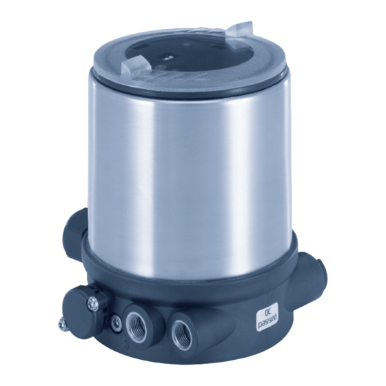
Actuator + Valve body = Process valve And also on the Internet at: Fig. 1: Structure 1 www.burkert.com Positioner Type 8694 is an electropneumatic position controller for pneumatically actuated control valves with single-acting actuators. Warranty Together with the pneumatic actuator, the positioner forms a functional unit. -
Page 8: Technical Data
Type 8694 Technicaldata TECHNICAL DATA Electrical connection (cable gland or circular Conformity plug-in connector) In accordance with the EC Declaration of conformity, the positioner Pressure limiting valve Type 8694 is compliant with the EC Directives. Communications interface Standards DIP Switches The applied standards, which verify conformity with the EC Direc- tives, can be found on the EC-Type Examination Certificate and / or the EC Declaration of Conformity. -
Page 9: Operating Conditions
Type 8694 Technicaldata Operating conditions Type labels WARNING! 6.6.1 Type label standard (example) Solar radiation and temperature fluctuations may cause mal- Operating voltage / functions or leaks. Control Control function - ▶ If the device is used outdoors, do not expose it unprotected to Type Pilot valve the weather conditions. 8694 24 V DC Max. -
Page 10: Ul Additional Label (Example)
Type 8694 Technicaldata 6.6.3 UL additional label (example) Plug-in hose connector ∅ 6 mm / 1/4“ Connections Socket connection G1/8 Electrical data Type 4X enclosure Degree of protection Circuit with limited power NEC Class 2 only WARNING! Supply voltage: 24V Supply voltage device Only circuits with limited power may be used for UL approved components according to “NEC Class 2”. -
Page 11: Electrical Data With As Interface Bus Control
Devices without external supply voltage: tions Type 8694. These instructions can be found on the Internet at Max. power consumption 150 mA www.burkert.com. Devices with external supply voltage: External supply voltage 24 V ± 10 % The power supply unit must include a secure disconnection in Without change to the settings via the communications software a linear accordance with IEC 364-4-41(PELV or SELV) characteristic is stored in FREE. -
Page 12: Installation
Type 8694 Installation INSTALLATION Installing the positioner on process valves belonging to series 2103 and Only for positioner without pre-assembled process valve. 23xx NOTE! When mounting on process valves with a welded body, follow Safety instructions the installation instructions in the operating instructions for the process valve. DANGER! When the positioner is being installed, the collets of the pilot Risk of injury from high pressure in the equipment/device. -
Page 13: Installing The Positioner On Process Valves Belonging To Series 26Xx And 27Xx
Type 8694 Installation → Installing the positioner on process Push the positioner, without turning it, onto the actuator until no gap is visible on the form seal. valves belonging to series 26xx and 27xx NOTE! Procedure: Too high torque when screwing in the fastening screw does Guide rail not ensure degree of protection IP65 / IP67. ▶... - Page 14 Type 8694 Installation Ensure that the pneumatic connections of the positioner and those of the actuator are situated preferably vertically Pilot air outlet 2 one above the other (see “Fig. 9”). Pilot air outlet 2 NOTE! Too high torque when screwing in the fastening screw does Fastening screws not ensure degree of protection IP65 / IP67. max.
-
Page 15: Pneumatic Installation
Type 8694 Pneumaticinstallation PNEUMATIC INSTALLATION Control function A (CFA) Process valve closed in rest position (by spring force) DANGER! ∅ 80, ∅ 100 Actuator size Risk of injury from high pressure in the equipment/device. ∅ 125 ▶ Before working on equipment or device, switch off the pressure Pilot air outlet and deaerate/drain lines. Procedure: →... -
Page 16: Electrical Installation
Type 8694 Electricalinstallation ELECTRICAL INSTALLATION Important information for the problem-free functioning of the device: All electrical inputs and outputs of the device are not galvanically ▶ The installation must not cause back pressure to build up. isolated from the supply voltage. ▶... -
Page 17: Electrical Installation With Cable Gland
Type 8694 Electricalinstallation 9.2.1 Electrical installation with cable gland Input signals from the control centre (e.g. PLC) NOTE! Terminal Configuration External circuit / signal level Breakage of the pneumatic connection pieces due to rota- tional impact. Set-point value + + (0/4 ... 24 mA) ▶ When unscrewing and screwing in the body casing, do not hold the actuator of the process valve but the connection housing. - Page 18 Type 8694 Electricalinstallation Output signals to the control center (e.g. PLC; for analog NOTE! output option only) Breakage of the pneumatic connection pieces due to rota- tional impact. Terminal Configuration External circuit / signal level ▶ When unscrewing and screwing in the body casing, do not hold the actuator of the process valve but the connection housing. Analogue position + (0/4 ...
- Page 19 Type 8694 Electricalinstallation 9.2.2 Electrical installation 24 V DC with Operating voltage circular plug-in connector Wire → Configuration External circuit Connect the positioner according to the table. color green 24 V DC ± 10 % max. residual ripple 10 % yellow + 24 V Tab.
-
Page 20: Electrical Installation As Interface
Type 8694 Electricalinstallation Electrical installation AS Interface Bus connection without external / with external supply voltage Designation Configuration A detailed description of the bus communication can be found in the operating instructions Type 8694. Bus + AS Interface bus line + NC or GND not used or external supply voltage –... -
Page 21: Start-Up
Type 8694 Start-up START-UP 10.1 Safety instructions WARNING! Risk of injury from improper operation. Improper operation may result in injuries as well as damage to the device and the area around it. ▶ Before start-up, ensure that the operating personnel are familiar with and completely understand the contents of the operating Fig. - Page 22 Type 8694 Start-up → Screw off the transparent cap of the positioner to operate the NOTE! keys and DIP switches. Avoid maladjustment of the controller due to an incorrect pilot pressure or applied operating medium pressure. ▶ Run X.TUNE whenever the pilot pressure (= pneumatic auxil- Communications iary energy) is available during subsequent operation. interface •...
-
Page 23: Control And Display Elements
Type 8694 Start-up 10.3 Control and display elements NOTE! A detailed description of the operation and functions of the Breakage of the pneumatic connection pieces due to rota- positioner and the communication software can be found in tional impact. the respective operating instructions. ▶ When unscrewing and screwing in the transparent cap, do not hold the actuator of the process valve but the connection housing. -
Page 24: Operating Status
Type 8694 Start-up 10.3.1 Operating status Communications interface AUTOMATIC (AUTO) LED 1 Normal controller mode is implemented and monitored in AUTO- MATIC operating state. LED 2 LED 1 flashes green. DIP Switches 1 2 3 4 MANUAL (MANU) Key 2 In MANUAL operating state the valve can be opened and closed Key 1 manually via the keys. -
Page 25: Functions Of The Keys
Type 8694 Start-up 10.3.2 Functions of the keys MANUAL operating status (DIP switch 4 set to ON): The configuration of the 2 keys on the board varies depending on the Function operating status (AUTOMATIC / MANUAL). Aerate (manually open / close the actuator) Communications Deaerate (manually open / close the actuator) interface... -
Page 26: Function Of The Dip Switches
Type 8694 Start-up 10.3.3 Function of the DIP switches 10.3.4 Display of the LEDs DIP Function Communications switches 1 2 3 4 interface LED 1 Reversal of the effective direction of the set-point value (set-point value 20 – 4 mA corresponds to LED 2 position 0 –... -
Page 27: Safety Positions
Type 8694 SafetyPositions LED 1 (green / red) SAFETY POSITIONS LED States Display Safety positions after green failure of the auxiliary Actuator Acceleration phase when Power ON Designation power system flashes slowly Operating status AUTO (AUTOMATIC) electrical pneumatic flashing flashing MANUAL operating status pilot-controlled alternating control system: flashes quickly X.TUNE function single-acting ERROR (see operating instructions) -
Page 28: Accessories
Inadequately protected equipment may be damaged during transport. Information at Communicator ▶ During transportation protect the device against wet and dirt in www.burkert.com shock-resistant packaging. Connection cable M12 x 1, 8-pole 919061 ▶ Avoid exceeding or dropping below the permitted storage... - Page 29 Typ 8694 Inhaltsverzeichnis Montage Positioner an Prozessventile der Reihe 26xx 1 DER QUICKSTART ..................30 und 27xx ..................39 Begriffsdefinition / Abkürzung ..........30 8 PNEUMATISCHE INSTALLATION ............41 Darstellungsmittel ..............30 2 BESTIMMUNGSGEMÄSSE VERWENDUNG........ 31 9 ELEKTRISCHE INSTALLATION ............42 Beschränkungen ..............31 Sicherheitshinweise ..............42 Elektrische Installation 24 V DC ..........42 3 GRUNDLEGENDE SICHERHEITSHINWEISE .
-
Page 30: Der Quickstart
Typ 8694 DerQuickstart DER QUICKSTART Darstellungsmittel Der Quickstart beschreibt den gesamten Lebenszyklus des Geräts. In dieser Anleitung werden folgende Darstellungsmittel verwendet. Bewahren Sie diese Anleitung so auf, dass sie für jeden Benutzer gut GEFAHR! zugänglich ist und jedem neuen Eigentümer des Geräts wieder zur Verfügung steht. -
Page 31: Bestimmungsgemässe Verwendung
Typ 8694 BestimmungsgemäßeVerwendung BESTIMMUNGSGEMÄSSE GRUNDLEGENDE VERWENDUNG SICHERHEITSHINWEISE Diese Sicherheitshinweise berücksichtigen keine Bei nicht bestimmungsgemäßer Verwendung des Positioners Typ 8694 können Gefahren für Personen, Anlagen in der • Zufälligkeiten und Ereignisse, die bei Montage, Betrieb und Wartung Umgebung und die Umwelt entstehen. der Geräte auftreten können. ▶ Das Gerät ist für den Anbau an pneumatische Antriebe von Pro- •... - Page 32 Typ 8694 GrundlegendeSicherheitshinweise Allgemeine Gefahrensituationen. Zum Schutz vor Sachschäden am Gerät ist zu beachten: ▶ In den Steuerluftanschluss des Systems keine aggressiven oder Zum Schutz vor Verletzungen ist zu beachten: brennbaren Medien einspeisen. ▶ Im explosionsgefährdeten Bereich darf der Positioner Typ 8694 ▶...
-
Page 33: Allgemeine Hinweise
Bedienungsanleitung. Bild 1: Aufbau Außerdem im Internet unter: Der Positioner Typ 8694 ist ein elektropneumatischer Stellungsregler www.burkert.com für pneumatisch betätigte Stellventile mit einfachwirkenden Antrieben. Der Positioner bildet mit dem pneumatischen Antrieb eine optische Gewährleistung und funktionelle Einheit. Voraussetzung für die Gewährleistung ist der bestimmungsgemäße Die Regelventilsysteme können für vielfältige Regelungsaufgaben in der... -
Page 34: Technische Daten
Typ 8694 TechnischeDaten TECHNISCHE DATEN Elektrischer Anschluss Konformität (Kabelverschraubung oder Rundsteckverbinder) Der Positioner Typ 8694 ist konform zu den EG-Richtlinien entspre- chend der EG-Konformitätserklärung. Druckbegrenzungsventil Kommunikationschnittstelle Normen DIP-Schalter Die angewandten Normen, mit denen die Konformität mit den EG-Richt- linien nachgewiesen wird, sind in der EG-Baumusterprüfbescheinigung und/oder der EG-Konformitätserklärung nachzulesen. -
Page 35: Betriebsbedingungen
Typ 8694 TechnischeDaten Betriebsbedingungen Typschilder WARNUNG! 6.6.1 Typschild Standard (Beispiel) Sonneneinstrahlung und Temperaturschwankungen können Betriebsspannung / Ansteuerung Steuerfunktion Fehlfunktionen oder Undichtheiten bewirken. - Steuerventil ▶ Das Gerät bei Einsatz im Außenbereich nicht ungeschützt den Witterungsverhältnissen aussetzen. 8694 24 V DC Max. Betriebsdruck single act Pilot 0,6 ▶... -
Page 36: Ul-Zusatzschild (Beispiel)
Typ 8694 TechnischeDaten 6.6.3 UL-Zusatzschild (Beispiel) Schlauchsteckverbinder ∅6 mm / 1/4“ Anschlüsse Muffenanschluss G1/8 Elektrische Daten Type 4X enclosure Schutzart Stromkreis mit begrenzter Leistung NEC Class 2 only WARNUNG! Supply voltage: 24V Versorgungsspannung Gerät Bei UL zugelassenen Komponenten dürfen nur Stromkreise begrenzter Leistung nach „NEC Class 2“... -
Page 37: Elektrische Daten Mit Bus-Ansteuerung As-Interface
Typ 8694 TechnischeDaten Werkseinstellungen des Positioners Digitaleingang 0...5 V = log „0“, 12...30 V = log „1“ Über DIP-Schalter aktivierbare Funktionen: invertierter Eingang entsprechend umgekehrt Kommunikations- Funktion Parameter Wert schnittstelle Direkter Anschluss an PC über USB-Adapter mit integriertem Schnittstellentreiber, Kommu- CUTOFF Dichtschließfunktion unten nikation mit Kommunikation-Software... -
Page 38: Montage
Typ 8694 Montage MONTAGE Montage Positioner an Prozessventile der Reihe 2103, 2300 und 2301 Nur für Positioner ohne vormontiertes Prozessventil. HINWEIS! Bei Montage an Prozessventile mit Schweißgehäuse die Mon- Sicherheitshinweise tagehinweise in der Bedienungsanleitung des Prozessventils beachten. GEFAHR! Bei der Montage des Positioners dürfen die Collets der Steu- Verletzungsgefahr durch hohen Druck in Anlage/Gerät. erluftanschlüsse am Antrieb nicht montiert sein. ▶... -
Page 39: Montage Positioner An Prozessventile Der Reihe 26Xx Und 27Xx
Typ 8694 Montage → Montage Positioner an Prozessventile Positioner ohne Drehbewegung soweit auf den Antrieb schieben, dass an der Formdichtung kein Spalt mehr sichtbar ist. der Reihe 26xx und 27xx HINWEIS! Vorgehensweise: Führungsschiene Durch ein zu hohes Drehmoment beim Einschrauben der Befestigungsschraube kann die Schutzart IP65 / IP67 nicht sichergestellt werden. ▶ Befestigungsschrauben nur mit einem maximalen Drehmoment von 1,5 Nm anziehen. - Page 40 Typ 8694 Montage Darauf achten, dass die pneumatischen Anschlüsse des Posi- tioners (2 und 2 )und die des Antriebs vorzugsweise vertikal Steuerluftausgang 2 übereinander liegen (siehe „Bild 9“). Steuerluftausgang 2 HINWEIS! Durch ein zu hohes Drehmoment beim Einschrauben der Befestigungsschrauben Befestigungsschraube kann die Schutzart IP65 / IP67 nicht max. 1,5 Nm sichergestellt werden. ▶ Die Befestigungsschraube darf nur mit einem maximalen Dreh- moment von 1,5 Nm angezogen werden.
-
Page 41: Pneumatische Installation
Typ 8694 PneumatischeInstallation PNEUMATISCHE INSTALLATION Steuerfunktion A (SFA) Prozessventil in Ruhestellung geschlossen (durch Federkraft) GEFAHR! ∅80, ∅100 Antriebsgröße Verletzungsgefahr durch hohen Druck in Anlage/Gerät. ∅125 ▶ Vor Arbeiten an Anlage oder Gerät, den Druck abschalten und Leitungen entlüften/entleeren. Steuerluftausgang Vorgehensweise: → Steuermedium an den Steuerluftanschluss (1) anschließen Steuerlufteingang oben (3...7 bar;... -
Page 42: Elektrische Installation
Typ 8694 ElektrischeInstallation ELEKTRISCHE INSTALLATION Wichtiger Hinweis zur einwandfreien Funktion des Geräts: ▶ Durch die Installation darf sich kein Rückdruck aufbauen. Alle elektrischen Eingänge und Ausgänge des Geräts sind zur Versor- gungsspannung nicht galvanisch getrennt. ▶ Für den Anschluss einen Schlauch mit ausreichendem Querschnitt wählen. - Page 43 Typ 8694 ElektrischeInstallation 9.2.1 Installation mit Kabelverschraubung Eingangssignale der Leitstelle (z. B. SPS) HINWEIS! Klemme Belegung äußere Beschaltung / Signalpegel Bruch der pneumatischen Verbindungsstutzen durch Dreheinwirkung. Sollwert + + (0/4...24 mA) ▶ Beim Abschrauben und Einschrauben des Gehäusemantels nicht am Antrieb des Prozessventils sondern am Anschlussgehäuse gegenhalten. Sollwert GND →...
- Page 44 Typ 8694 ElektrischeInstallation Ausgangssignale zur Leitstelle (z. B. SPS) - (nur bei Option HINWEIS! Analogausgang erforderlich) Bruch der pneumatischen Verbindungsstutzen durch Dreheinwirkung. Klemme Belegung äußere Beschaltung / Signalpegel ▶ Beim Abschrauben und Einschrauben des Gehäusemantels nicht am Antrieb des Prozessventils sondern am Anschlussgehäuse Analoge Stellungs- + (0/4...24 mA) gegenhalten.
- Page 45 Typ 8694 ElektrischeInstallation 9.2.2 Installation mit Rundsteckverbinder Betriebsspannung → Positioner entsprechend den Tabellen anschließen. Ader- Belegung äußere Beschaltung farbe grün 24 V DC ±10 % max. Restwelligkeit 10 % gelb +24 V Tab. 7: Pin-Belegung - Betriebsspannung Bild 14: Belegung Rundstecker (M12 x 1, 8-polig) Ausgangssignale zur Leitstelle (z.
-
Page 46: Installation Für As-Interface
Typ 8694 ElektrischeInstallation Installation für AS-Interface Bus-Anschluss ohne externe / mit externer Versorgungsspannung Die detaillierte Beschreibung der Bus-Kommunikation Bezeichnung Belegung finden Sie in der Bedienungsanleitung von Typ 8694. Bus + Bus-Leitung AS-Interface + 9.3.1 Elektrischer Anschluss mit NC oder GND nicht belegt oder externe Versorgungs- Rundsteckverbinder M12 x 1, 4-polig (optional) -
Page 47: Inbetriebnahme
Typ 8694 Inbetriebnahme INBETRIEBNAHME 10.1 Sicherheitshinweise WARNUNG! Verletzungsgefahr bei unsachgemäßem Betrieb. Nicht sachgemäßer Betrieb kann zu Verletzungen, sowie Schäden am Gerät und seiner Umgebung führen. ▶ Vor der Inbetriebnahme muss gewährleistet sein, dass der Inhalt der Bedienungsanleitung dem Bedienungspersonal bekannt ist Bild 17: Positioner 8694 mit Multipolkabel und Flachkabelklemme und vollständig verstanden wurde. - Page 48 Typ 8694 Inbetriebnahme → Klarsichthaube gegen den Uhrzeigersinn aufschrauben. HINWEIS! Durch einen falschen Steuerdruck oder aufgeschalteten Kommunikations- Betriebsdruck am Ventilsitz kann es zur Fehlanpassung des schnittstelle Reglers kommen. LED 1 ▶ X.TUNE in jedem Fall bei dem im späteren Betrieb zur Ver- fügung stehenden Steuerdruck (= pneumatische Hilfsenergie) LED 2 durchführen. DIP-Schalter ▶ Die Funktion X.TUNE vorzugsweise ohne Betriebsmediumsdruck 1 2 3 4 durchführen, um Störeinflüsse infolge von Strömungskräften Taste 2...
-
Page 49: Bedienung Und Anzeigeelemente
Typ 8694 Inbetriebnahme 10.3 Bedienung und Anzeigeelemente HINWEIS! Eine detaillierte Beschreibung der Bedienung und Funktionen Bruch der pneumatischen Verbindungsstutzen durch des Positioners und der Kommunikation-Software finden Sie Dreheinwirkung. in der jeweiligen Bedienungsanleitung. ▶ Beim Abschrauben und Einschrauben der Klarsichthaube nicht am Antrieb des Prozessventils sondern am Anschlussgehäuse HINWEIS! gegenhalten. - Page 50 Typ 8694 Inbetriebnahme 10.3.1 Betriebszustand Kommunikations- schnittstelle AUTOMATIK LED 1 Im Betriebszustand AUTOMATIK wird der normale Reglerbetrieb ausgeführt und überwacht. LED 2 LED 1 blinkt grün. DIP-Schalter 1 2 3 4 HAND Taste 2 Im Betriebszustand HAND kann das Ventil manuell über die Tasten Taste 1 auf- oder zugefahren werden.
-
Page 51: Funktion Der Tasten
Typ 8694 Inbetriebnahme 10.3.2 Funktion der Tasten Betriebszustand HAND (DIP-Schalter 4 auf ON): Die Belegung der 2 Tasten sind je nach Betriebszustand (AUTOMATIK Taste Funktion / HAND) unterschiedlich. Belüften (manuelles Auf- oder Zufahren des Antriebs) Kommunikations- Entlüften (manuelles Auf- oder Zufahren des Antriebs) schnittstelle Tab. -
Page 52: Funktion Der Dip-Schalter
Typ 8694 Inbetriebnahme 10.3.3 Funktion der DIP-Schalter 10.3.4 Anzeige der LEDs DIP- Funktion Kommunikations- Schalter 1 2 3 4 schnittstelle Umkehr der Wirkrichtung des Sollwerts LED 1 (20...4 mA entspricht 0...100 %), fallend (DIR.CMD) LED 2 normale Wirkrichtung des Sollwerts DIP-Schalter (4...20 mA entspricht 0...100 %), steigend 1 2 3 4... -
Page 53: Sicherheitsstellungen
Typ 8694 Sicherheitsstellungen LED 1 (grün / rot) SICHERHEITSSTELLUNGEN LED-Zustände Anzeige Sicherheitsstellungen nach grün Ausfall der Hilfsenergie Antriebssart Bezeichnung Hochlaufphase bei Power ON elektrisch pneumatisch blinkt langsam Betriebszustand AUTO blinkt blinkt Betriebszustand HAND vorgesteuertes Stellsystem: im Wechsel einfach- blinkt schnell X.TUNE Funktion down wirkend FEHLER down direktwir- Steuer- (siehe Bedienungsanleitung) kendes... -
Page 54: Zubehör
Typ 8694 Zubehör ZUBEHÖR TRANSPORT, LAGERUNG, VERPACKUNG Bezeichnung Bestell-Nr. HINWEIS! USB-Adapter zum Anschluss eines PC in 227093 Transportschäden. Verbindung mit einem Verlängerungskabel Unzureichend geschützte Geräte können durch den Transport Infos unter Communicator beschädigt werden. www.buerkert.de ▶ Gerät vor Nässe und Schmutz geschützt in einer stoßfesten Ver- Anschlusskabel M12 x 1, 8-polig 919061 packung transportieren. - Page 55 Type 8694 Sommaire Montage du positionneur type 8694 sur les vannes 1 QUICKSTART ....................56 process des séries 26xx et 27xx ..........65 Définition du terme / abréviation ..........56 8 INSTALLATION PNEUMATIQUE ............67 Symboles ...................56 2 UTILISATION CONFORME ..............57 9 INSTALLATION ÉLECTRIQUE .............
-
Page 56: Quickstart
Type 8694 Quickstart QUICKSTART Symboles Quickstart décrit le cycle de vie complet de l’appareil. Conservez-le Les moyens de représentation suivants sont utilisés dans les présentes manuels d’utilisation. de sorte qu’il soit accessible à tout utilisateur et à disposition de tout nouveau propriétaire. -
Page 57: Utilisation Conforme
Type 8694 Utilisationconforme UTILISATION CONFORME CONSIGNES DE SÉCURITÉ FONDAMENTALES L’utilisation non conforme du positionneur type 8694 peut présenter des dangers pour les personnes, les installations Ces consignes de sécurité ne tiennent pas compte proches et l’environnement. • des hasards et des événements pouvant survenir lors du montage, ▶ L’appareil est conçu pour être monté sur les actionneurs pneu- de l’exploitation et de l’entretien des appareils. - Page 58 Type 8694 Consignesdesécuritéfondamentales ▶ Lors du vissage et du dévissage de l’enveloppe du corps ou du Situations dangereuses d’ordre général. capot transparent ne pas exercer de contre pression sur l’action- Pour prévenir les blessures, respectez ce qui suit : neur de la vanne process mais sur le corps de raccordement du ▶...
-
Page 59: Indications Générales
Fig. 1 : Structure 1 Egalement sur internet sous : Le positionneur type 8694 est un régulateur de position électropneu- www.burkert.com matique pour vannes de régulation à commande pneumatique avec Garantie légale actionneur simple effet. Le positionneur forme un ensemble fonctionnel avec l’actionneur pneumatique. -
Page 60: Caractéristiques Techniques
Type 8694 Caractéristiquestechniques CARACTÉRISTIQUES TECHNIQUES Raccordement élec- trique (presse-étoupe ou Conformité connecteur rond) Le positionneur type 8694 est conforme aux directives CE sur la Limiteur de pression base de la déclaration de conformité CE. Interface de communication Normes Interrupteur DIP Les normes appliquées justifiant la conformité... -
Page 61: Conditions D'exploitation
Type 8694 Caractéristiquestechniques Conditions d’exploitation Plaques signalétiques AVERTISSEMENT ! 6.6.1 Plaque signalétique standard (exemple) Le rayonnement solaire et les variations de température Tension d’alimentation / peuvent être à l'origine de dysfonctionnements ou de fuites. Commande Fonction - ▶ Lorsqu'il est utilisé à l'extérieur, n'exposez pas l'appareil aux Type Vanne pilote intempéries sans aucune protection. 8694 24 V DC Pression maxi ▶... -
Page 62: Plaque Supplémentaire Ul (Exemple)
Type 8694 Caractéristiquestechniques 6.6.3 Plaque supplémentaire UL (exemple) Connecteur de flexible ∅ 6mm / 1/4“ Raccordements Raccord manchon G 1/8 Degré de protection Type 4X enclosure Caractéristiques électriques NEC Class 2 only Circuit électrique à puissance limitée Supply voltage: 24 V Tension d’alimentation de l’appareil AVERTISSEMENT ! Fig. -
Page 63: Réglages Usine Du Positionneur
Type 8694 Caractéristiquestechniques Message de retour de Courant absorbé maxi 100 mA position analogique charge Courant absorbé maxi maxi pour sortie de courant de l’interface AS 50 mA 560 Ω 0/4 ... 20 mA Réglages usine du positionneur Entrée numérique 0 ... -
Page 64: Montage
Type 8694 Montage MONTAGE Montage du positionneur type 8694 sur les vannes process des séries Uniquement pour positionneur sans vanne process prémontée. 2103 et 23xx REMARQUE ! Consignes de sécurité Lors du montage sur les vannes process à corps soudé, DANGER ! observer les consignes de montage dans le manuel d‘utilisation de la vanne process. -
Page 65: Montage Du Positionneur Type 8694 Sur Les Vannes Process Des Séries 26Xx Et 27Xx
Type 8694 Montage → Montage du positionneur type 8694 Glisser le positionneur sur l’actionneur sans la faire tourner jusqu’à ce que le joint profilé ne présente plus d’interstice. sur les vannes process des séries 26xx et 27xx REMARQUE ! Procédure à suivre : Le degré de protection IP65 / IP67 ne peut être garanti si le Rail de guidage couple de serrage de la vis de fixation est trop élevé. - Page 66 Type 8694 Montage Veillez à ce que les raccordements pneumatiques du posi- tionner et ceux de l’actionneur soient de préférence super- Sortie d’air de pilotage 2 posés (voir « Fig. 9 »). Sortie d’air de pilotage 2 REMARQUE ! Le degré de protection IP65 / IP67 ne peut être garanti si le Vis de fixation (2x) couple de serrage de la vis de fixation est trop élevé.
-
Page 67: Installation Pneumatique
Type 8694 Installationpneumatique INSTALLATION PNEUMATIQUE Fonction A (CFA) Vanne process fermée en position de repos (par ressort) DANGER ! ∅ 80, ∅ 100 Tailles d’actionneur Risque de blessures dû à la présence de haute pression dans ∅ 125 l‘installation/l‘appareil. Sortie d’air de pilotage ▶ Avant de travailler sur l’installation ou l’appareil, il convient de couper la pression et de purger des conduites/de les vider. -
Page 68: Installation Électrique
Type 8694 Installationélectrique INSTALLATION ÉLECTRIQUE Remarque importante concernant le parfait fonctionnement de l’appareil : Toutes les sorties et entrées de l’appareil ne sont pas à séparation ▶ L’installation ne doit pas générer de contre-pression. galvanique pour la tension d’alimentation. ▶ Pour le raccordement, choisissez un flexible d’une section Consignes de sécurité... -
Page 69: Installation Électrique Avec Presse-Étoupe
Type 8694 Installationélectrique 9.2.1 Installation électrique avec Signaux d’entrée du poste de commande (par ex. API) presse-étoupe Borne Affectation Câblage externe / niveau de signal REMARQUE ! Rupture des manchons pneumatiques due à la torsion. Valeur de + (0/4 ... 24 mA) consigne + ▶ Pour dévisser et visser l’enveloppe du corps, ne pas exercer de contre pression sur l’actionneur de vanne process mais sur le corps de raccordement. - Page 70 Type 8694 Installationélectrique Signaux de sortie vers le poste de commande (par ex. API ; REMARQUE ! uniquement avec l’option sortie analogique) Rupture des manchons pneumatiques due à la torsion. Câblage externe / niveau de ▶ Pour dévisser et visser l’enveloppe du corps, ne pas exercer de Borne Affectation signal contre pression sur l’actionneur de vanne process mais sur le corps de raccordement.
-
Page 71: Installation Électrique Avec Connecteur Rond
Type 8694 Installationélectrique 9.2.2 Installation électrique avec connecteur Tension de service rond Couleur → Broche Affectation Câblage externe Raccorder le positionneur conformément au tableau. de fil vert 24 V DC ± 10 % ondulation rési- duelle maxi 10 % jaune + 24 V Tab. 7 : Affectation des broches ;... -
Page 72: Installation Électrique Interface As
Type 8694 Installationélectrique Installation électrique Interface AS Raccordement bus sans / avec tension d’alimentation externe Broche Désignation Affectation Une description détaillée du bus de communication est décrite dans le manuel d’utilisation type 8694. Bus + Câble bus interface AS + NC ou GND non affecté... -
Page 73: Données De Programmation
Type 8694 Miseenservice MISE EN SERVICE 10.1 Consignes de sécurité AVERTISSEMENT ! Risque de blessures dû à un montage non conforme. Une utilisation non conforme peut entraîner des blessures et endommager l’appareil et son environnement. ▶ Avant la mise en service, il faut s’assurer que le contenu des manuels d’utilisation est connu et parfaitement compris par les Fig. - Page 74 Type 8694 Miseenservice → Pour commander les touches et les interrupteurs DIP, dévisser le REMARQUE ! capot transparent. Evitez une mauvaise adaptation du régulateur suite à une pression de pilotage ou une pression de fluide de service erronée. ▶ Exécutez dans tous les cas X.TUNE avec la pression de pilotage Interface de disponible lors du fonctionnement ultérieur (= énergie auxiliaire communication...
-
Page 75: Éléments De Commande Et D'affichage
Type 8694 Miseenservice 10.3 Éléments de commande et REMARQUE ! d’affichage Rupture des manchons pneumatiques due à la torsion. Une description détaillée de la commande et des fonctions ▶ Pour dévisser et visser le capot transparent, ne pas exercer de du positionneur et du logiciel de communication est décrite contre pression sur l’actionneur de vanne process mais sur le dans les manuels d’utilisation respectifs. -
Page 76: Etat De Marche
Type 8694 Miseenservice 10.3.1 Etat de marche Interface de communication AUTOMATIQUE (AUTO) LED 1 A l’état de marche AUTOMATIQUE, le fonctionnement normal du régulateur est effectué et surveillé. LED 2 La LED 1 clignote en vert. Interrupteur DIP 1 2 3 4 MANUEL (MANU) Touche 2 A l’état de marche MANUEL, la vanne peut être ouverte ou fermée... -
Page 77: Fonction Des Touches
Type 8694 Miseenservice 10.3.2 Fonction des Etat de marche MANUEL (interrupteur DIP 4 sur ON) : touches L’affectation des 2 touches sur la carte est différente en fonction de Touche Fonction l’état de marche (AUTOMATIQUE / MANUEL). Alimentation en air (ouverture / fermeture manuelle de l'actionneur) Interface de Echappement... -
Page 78: Fonction Des Interrupteurs Dip
Type 8694 Miseenservice 10.3.3 Fonction des interrupteurs DIP 10.3.4 Affichage des LED Interrup- Fonction Interface de teurs DIP 1 2 3 4 communication LED 1 Inversion du sens d’action de la valeur de consigne (la valeur de consigne 20 ... 4 mA correspond à la LED 2 position 0 ... -
Page 79: Affichage
Type 8694 Miseenservice LED 1 (vert / rouge) LED 2 (vert / jaune) Etats des LED Etats des LED Affichage Affichage vert rouge vert jaune allumée éteinte Phase de démarrage pour Power ON allumée éteinte actionneur fermé clignote éteinte éteinte allumée actionneur ouvert Etat de marche AUTO (AUTOMATIQUE) lentement clignote Écart de régulation permanent... -
Page 80: Positions De Sécurité
Type 8694 Positionsdesécurité POSITIONS DE SÉCURITÉ ACCESSOIRES N° de Réglages de sécurité après Désignation commande une panne de l’énergie Type Désignation Adaptateur USB pour le raccordement d'un auxiliaire d’actionneur 227093 PC en liaison avec un câble de rallonge électrique pneumatique Infos sous système de Communicator www.buerkert.fr réglage à Câble de raccordement M12 x1, 8 pôles 919061 action pilotée :... -
Page 81: Téléchargement
Type 8694 Emballage,Transport,Stockage 12.3 Téléchargement EMBALLAGE, TRANSPORT, STOCKAGE Téléchargement du logiciel sous : www.buerkert.fr REMARQUE ! Dommages dus au transport. Les appareils insuffisamment protégés peuvent être endommagés pendant le transport. ▶ Transportez l'appareil à l'abri de l'humidité et des impuretés et dans un emballage résistant aux chocs. ▶... - Page 82 Type 8694 Emballage,Transport,Stockage français...
- Page 84 www.burkert.com...