Burkert 8045 Mode D'emploi
Masquer les pouces Voir aussi pour 8045:
Table des Matières

Publicité

Les langues disponibles

Les langues disponibles

Liens rapides

8045
MAGNETISCH - INDUKTIVER
DURCHFLUSSTRANSMITTER
BEDIENUNGSANLEITUNG
Ref. 426532 - Ind*3/Jan03
Fluid Control Systems

Publicité

Table des Matières
loading

Sommaire des Matières pour Burkert 8045

  • Page 1 8045 MAGNETISCH - INDUKTIVER DURCHFLUSSTRANSMITTER BEDIENUNGSANLEITUNG Ref. 426532 - Ind*3/Jan03 Fluid Control Systems...
  • Page 2: Table Des Matières

    4.5.4 Durchflusssimulation ....................32 Einstellungen des 8045 ......................33 4.6.1 Durchflusstransmitter 8045 bei Auslieferung ............33 4.6.2 Benutzerkonfiguration für den Durchflusstransmitter 8045 ........33 WARTUNG Aufbewahrung und Reinigung des Sensors .............. 34 Fehlersuche ......................34-35 TECHNISCHE DATEN Technische Daten ....................36-37 Abmessungen ......................
  • Page 3: Einführung

    Wartungsmaßnahmen sowie zu Ersatzteilen. ALLGEMEINE SICHERHEITSANWEISUNGEN Herzlichen Glückwunsch zum Erwerb unseres magnetisch-induktiven Durchflusstransmitters 8045. Lesen Sie vor der Installation und Benutzung des Geräts bitte diese Bedienungsanleitung sowie alle anderen relevanten Dokumentationen. Nur so können Sie alle Leistungsmerkmale nutzen, die das Gerät bietet.
  • Page 4: Quickstart

    QUICKSTART Dieser Abschnitt bietet eine umfassende Anleitung für Installation und Betrieb des Gerätes, die Ihnen die Inbetriebnahme des Durchflusstransmitters 8045 erleichtert. INSTALLATION Auf Vollständigkeit überprüfen Auspacken Siehe Abschnitt 6.5 Falsch Siehe Bestell-Nr. Wenden Sie sich an Ihre örtliche Abschnitt 6.4 überprüfen...
  • Page 5: Programmierung

    1 Dezimalstelle und m für die 4.4.2 Einheiten auswählen Zähleranzeige. Siehe Abschnitt = K-Faktor des Fittings x K-Faktor eingeben 8045 4.4.3 F s Koeff. auf dem Etikett. 4 mA = 0 l/s und Siehe Abschnitt Ausgangssignal- 20 mA = 10 l/s. 4.4.4...
  • Page 6: Testen

    Siehe Dieser Schritt ist optional, wird Simulation der Abschnitt 4.5.4 aber besonders für die Ausgänge Inbetriebnahme umfangreicher Systeme empfohlen. Das Gerät ist jetzt bereit. Die grau hervorgehobenen Anweisungen müssen für eine genaue Messung vollständig ausgeführt werden. 8045 Fluid Control Systems...
  • Page 7: Installation

    INSTALLATION RICHTLINIEN FÜR DIE INSTALLATION Druck-Temperatur-Diagramm für Kunststoff-Fittings Beachten Sie bitte die in den folgenden Diagrammen dargestellte Abhängigkeit zwischen Mediums-Druck und -Temperatur je nach Fitting+Sensor-Material. 8045 mit PVDF-Sensor: P (Bar) Anwendungsbereich Medium PVDF PVDF (PN 6) / Messing/Edelstahl PVC + PP...
  • Page 8 Dies gilt besonders dann, wenn das Rohr gefährliche, aggressive, heiße oder unter hohen Druck gesetzten Flüssigkeiten enthält. 3.1.1 MONTAGEHINWEISE Der magnetisch-induktive Durchflusstransmitter 8045 kann auf verschiedene Weise montiert werden, um eine genaue Durchflussmessung zu erhalten; der Rohrleitungsaufbau sollte jedoch so gestaltet sein, dass das Rohr zu jedem Zeitpunkt vollständig gefüllt ist.
  • Page 9 Die Mindesteinlauf (10 x DN) und -auslaufstrecken (3 x DN) müssen eingehalten werden. Vergewissern Sie sich bitte, dass der Rohrleitungsaufbau nicht die Bildung von Luftblasen oder -einschlüssen im Medium begünstigt, da diese Messfehler verursachen. Strömungsrichtung Strömungsrichtung Richtig Falsch Richtig Falsch 8045 Fluid Control Systems...
  • Page 10: Installation

    INSTALLATION INSTALLATION Der Durchflusstransmitter 8045 kann mit speziell entwickelten Bürkert-Fittings S020 einfach in Rohrleitungen installiert werden. Der Fitting muss gemäß den in Abschnitt 3.1 angegebenen Montageanweisungen im Rohr installiert werden. Überwurfmutter auf den Fitting schieben und den Kunststoffring in der Führungsbuchse...
  • Page 11: Allgemeiner Elektrischer Anschluss

    Transmitter in die Rohrleitung ein und schliessen Sie diese Teile an den selben Erdungspunkt an. Die in nachfolgend abgebildetem Diagramm gezeigten Erdungsringe benötigen Kontakt zur Flüssigkeit. Sie werden von Bürkert nicht mitgeliefert. Metallische Für Kunststoffrohr-Anwendungen Apparate Edelstahl 8045 Fluid Control Systems...
  • Page 12: Verdrahtung Des Durchflusstransmitters 8045

    Anschließend das Kabel durch den Kabelanschluss ziehen und lt. Anschlussplänen anklemmen. Die Elektronik im 8045 ermöglicht den Anschluss einer mit einem 4-20 mA-Eingang versehenen SPS als Quelle oder Senke. Position A (Abb. 3.3) zeigt eine Konfiguration als Quelle und Position B (Abb. 3.4) eine Konfiguration als Senke.
  • Page 13: Vdc Mit Relais

    Programmierungs- und Testmenü zu verhindern. Wenn Schalter 2 nicht in Sperrposition ist, können die Parameterwerte (K-Faktor, Relais, Strom, ...) geändert werden. Wenn er sich in Sperrposition befindet, ist der Zugriff auf das Programmierungs- und Testmenü beschränkt. 8045 Fluid Control Systems...
  • Page 14: Anschluss Des Impulsausgangs

    Vergewissern Sie sich, dass in Schaltungen nach den oben dargestellten Abbildungen die Stromstärke 100 mA nicht überschreitet. Zur Berechnung der Bürde kann die folgende Gleichung verwendet werden: Bürde = U Beispiel: = 30 V = 20 mA Bürde = 1500 Ω 8045 Fluid Control Systems...
  • Page 15: Anschluss-Beispiele

    INSTALLATION ANSCHLUSS-BEISPIELE PNEUMATISCHE DURCHFLUSSREGELUNG 300 mA REL 1 24 V= 4-20 mA Beispiel eines Anschlusses zwischen dem Durchflusstransmitter 8045, 18-36 VDC, und dem auf ein Membranventil 2031 montierten Top Control. 8045 Fluid Control Systems...
  • Page 16 + 24 V I/O4 I/O3 I/O2 I/O1 GND2 I2 GND1 4-20 mA 0-10 V 24 VDC 0/4-20 mA POSITIONER 1067 Beispiel eines Anschlusses zwischen dem Durchflusstransmitter 8045, 18-36 VDC, und dem auf ein Membranventil 2031 montierten Positioner 1067. 8045 Fluid Control Systems...
  • Page 17 REL 1 Schaltventil REL2 24 V= Auf/Zu Top Control Beispiel eines Anschlusses zwischen dem Durchflusstransmitter 8045, 18-36 VDC, und dem auf ein Membranventil 2031 montierten Top Control 8631 und zwichen dem Transmitter 8045 und dem Schaltventil 6012. 8045 Fluid Control Systems...
  • Page 18: Bedienung

    Zugriff auf oder Rückkehr zum 0..9 TESTMENÜ* 5 Sekunden * Nur über das Hauptmenü erreichbar. ENTER -Taste kann gesperrt werden, um unbeabsichtigten bzw. unerlaubten Zugriff zu verhindern. Weitere Hinweise finden Sie in den Abschnitten 3.4.1 und 3.4.3. 8045 Fluid Control Systems...
  • Page 19: Menüführung

    BEDIENUNG MENÜFÜHRUNG Die nachfolgend dargestellte Menüführung unterstützt Sie bei der Auswahl und Einstellung eines gewünschten Parameters und bei der Programmierung des Durchflusstransmitters 8045. ENTER 0..9 0..9 ENTER 0..9 KALIBRIERMENÜ 0..9 SPRACHE TESTMENÜ 0..9 E I N H E I T OFFSET 0..9...
  • Page 20: Hauptmenü

    6247 L . angezeigt wie der Hauptzähler. Durch einen Punkt hinter der Einheit kann dieser Zähler vom Hauptzähler unterschieden werden. Um diesen Wert zurückzusetzen, halten Sie die Tasten 0..9 in diesem Menü zwei Sekunden lang gedrückt. 8045 Fluid Control Systems...
  • Page 21: Kalibriermenü

    4.4.8 automatisch mit.) FREQUENZ Auswahl der Wechselstromfrequenz 4.4.9 (50 oder 60 Hz). ENDE Zurück zum Hauptmenü und Abspeicherung der neuen Parameter. In den folgenden Abschnitten wird erläutert, wie die Parameterwerte im oben abgebildeten Kalibriermenü geändert werden. 8045 Fluid Control Systems...
  • Page 22 Menüpunkt weiter. LITER Rückkehr zum Hauptmenü über das Untermenü ”TOTAL”. K-FAKTOR Der Durchfluss kann in sämtlichen physikalischen Einheiten mit 0, 1, 2 oder 3 Dezimalstellen angezeigt werden (außer m /min). 8045 Fluid Control Systems...
  • Page 23: K-Faktor

    Für die manuelle Berechnung und Eingabe des K-Faktors kann die folgende Gleichung verwendet werden. Nachdem Sie den Wert ermittelt haben, wählen Sie “TEACH N“ im Menüpunkt K-FAKTOR und geben ihn ein. Ausführung mit PVDF-Sensor: Fitting 8045 Ausführung mit Edelstahl-Sensor: Fitting 8045 Dabei gilt:...
  • Page 24 Ende der derselben Kommas gleichzeitig. Messung. Einheit wie im Punkt 4.4.2 STROM festgelegt ein. Beginn der Anzeige des berechneten Messung. DURCHFLU K-Faktors. MESSUNG 50 s Messung. Geben Sie den Anzeige des berechneten gemessenen K-Faktors. Durchfluss ein. STROM 8045 Fluid Control Systems...
  • Page 25: Ausgangsstrom

    Messbereichs ein. Geben Sie das Ende des Messbereichs ein. In der folgenden Abbildung wird ein Beispiel für die Beziehung zwischen dem 4-20 mA-Ausgang und dem entsprechenden Messbereich dargestellt. Tatsächlicher Durchfluss l/ min Abbildung 4.1 - Ausgangssignal 8045 Fluid Control Systems...
  • Page 26: Impulsausgang

    Falls die Impulsfrequenz geringer als 2 Hz ist, wird der Impulswert gleich 250 ms sein. Falls die Impulsfrequenz größer als 2 Hz ist, wird das Taktverhältnis gleich 50% sein. Bei Q größer als 250 Hz wird die Impulsfrequenz gleich 0.00 Hz Pu gesetzt. 8045 Fluid Control Systems...
  • Page 27: Relais (Option)

    Relaisstromkreis (max. 3 A) eingehalten werden. 1- und 2- = die niedrigen Einstellungen für beide Relais 1+ und 2+ = die hohen Einstellungen für beide Relais Kontakt Invertieren nein OFFEN Durchfluss Kontakt Invertieren ja OFFEN Durchfluss ENTER 8045 Fluid Control Systems...
  • Page 28: Filterfunktion

    Wählen Sie den Filtertyp aus. ENTER Aus dem folgenden Diagramm ist ersichtlich, wie die verschiedenen Filter das Durchflusssignal über die Zeit beeinflussen. FILTER 3 Langsam Schnell FILTER 0 - Istwert FILTER 6 Langsam Schnell FILTER 9 Langsam Schnell 8045 Fluid Control Systems...
  • Page 29: Zähler

    Um die Störsignale zu filtern, geben Sie die Frequenz der Hauptstromquelle ein. ENTER F = 50 HZ FREQUENZ 0..9 Frequenzauswahl F = 60 HZ ENTER ENDE Die Einstellungen in diesem Menüpunkt müssen auch dann vorgenommen werden, wenn der Transmitter an eine Gleichstromversorgung angeschlossen ist. 8045 Fluid Control Systems...
  • Page 30: Testmenü

    Kehren Sie in des Hauptmenü zurück und speichern Sie die neuen Parameter für KALIB 0, OFFSET und SPAN. Wenn die OFFSET/SPAN- Werte unzulässig sind, kehrt das Gerät zu ”OFFSET” zurück, und es müssen neue Werte eingegeben werden. 8045 Fluid Control Systems...
  • Page 31: Offset-Abgleich

    Transmitteranzeige falsch ist, kann sie korrigiert werden, indem der gemessene Wert eingegeben wird. Einstellbereich: + / - 0.5 mA Geben Sie den gemessenen Wert ein. KALIB 0 ENTER Der korrigierte 20 mA- Wert wird bei Drücken der Taste übernommen, wenn “END“ im Testmenü angezeigt wird. 8045 Fluid Control Systems...
  • Page 32: Kalibrierung Des Durchfluss-Nullpunkts

    In diesem Menü kann ein Durchfluss simuliert werden, so dass der Benutzer das System ohne Flüssigkeit testen kann. Der simulierte Wert beeinflusst alle Ausgänge einschließlich Relais- und Impulsausgang. Geben Sie den Durchflusswert ein. Drücken Sie die Taste oder , um die Durchflusssimulation zu 0..9 beenden. 8045 Fluid Control Systems...
  • Page 33: Durchflusstransmitter 8045 Bei Auslieferung

    INFORMATIONEN EINSTELLUNGEN FÜR DEN 8045 4.6.1 DURCHFLUSSTRANSMITTER 8045 BEI AUSLIEFERUNG Sprache Englisch Relais 00,00 Einheit für Durchfluss 00,00 Einheit für Zähler Invertiert: Nein Dezimalstellen 00,00 K-Faktor 00,00 Strom 4 mA 00,00 Invertiert: Nein 20 mA 00,00 Filter Filter 2 Langsam...
  • Page 34: Wartung

    WARTUNG 5.1 AUFBEWAHRUNG UND REINIGUNG DES SENSORS Ordnungsgemäß installiert, ist der Durchflusstransmitter 8045 wartungsfrei. Bei Verunreinigungen oder Verstopfung während des Betriebs kann der Sensor mit Wasser oder einem anderen Reinigungsmittel, das mit PVDF und VA316L verträglich ist, gereinigt werden. 24 Stunden nach der Reinigung der Elektroden oder nach einem Wechsel des Mediums sollte der Nullpunkt kalibriert werden.
  • Page 35 4.4.6 programmieren Relais korrekt angeschlossen? Nein Relais anschließen Anschluss der Relais 1 und 2 vertauscht? Relais richtig anschließen Schutzsicherungen für die Relais OK? Nein Sicherungen auswechseln —— Relaisschalter auf ON ? Nein Schalter auf ON —— 8045 Fluid Control Systems...
  • Page 36 PVDF oder Edelstahl 316L (DIN 1.4404) Elektroden Edelstahl 316L (DIN 1.4404) Erdungsring (bei PVDF-Sensor) Edelstahl 316L (DIN 1.4404) Dichtungen EPDM (Standard bei einer Ausführung mit Edelstahl- Sensor) FPM (Standard bei einer Ausführung mit PVDF-Sensor) Elektrodengehäuse (bei Edelstahl-Sensor) PEEK 8045 Fluid Control Systems...
  • Page 37: Technische Daten

    Erzeugter Strom: xx.xx mA Relaisstatus Rote LEDs leuchten, wenn Kontakt geschlossen Programmierung Menüführung über 3 Tasten Sicherheit Schalter zum Sperren der ‘Enter‘-Taste Prozess Durchflussfilter 10 Filterstufen (Filter 0...9, in schnellem oder langsamen Modus) Temperaturkoeffizient (vgl. Abschnitt 4.4.3.1) 8045 Fluid Control Systems...
  • Page 38: Abmessungen

    PPA mit 33% Glasfaserverstärkung Frontabdeckung Polyester Schutzdeckel Topas COC (nur Ausführung mit Edelstahl-Sensor) Normenkonformität Störaussendung Entspricht Grundnorm EN 50081-1 Störfestigkeit Entspricht Grundnorm EN 50082-2 Sicherheit Entspricht Grundnorm EN 61010-1 ABMESSUNGEN Variable Abmessungen (in mm) ”STANDARD ”NORDAMERIKA” WELTWEIT” 8045 Fluid Control Systems...
  • Page 39: Aufbau Und Messverfahren

    INFORMATIONEN AUFBAU UND MESSVERFAHREN Aufbau Der kompakte Durchflusstransmitter 8045 besteht aus einem Durchflusssensor und einem Messwertwandler (Elektronikmodul) mit Anzeige in einem spritzwassergeschützten IP65-Kunststoffgehäuse. Im Unterteil des Sensorfingers befinden sich ein Elektromagnet und 2 in die Flüssigkeit ragende Elektroden zur Abnahme der induzierten Spannung.
  • Page 40: Lieferprogramm

    ANHANG LIEFERPROGRAMM Magnetisch-Induktiver Durchflusstransmitter 8045 Weltweit Typen: Elektrischer Anschluss Kabeldurchführung Ausgang 4-20 mA; Impulsausgang; 2 Zähler Betriebs- Sensor- Kabel- Spannung Relais Gehäuse Dichtung Bauweise durchf. Bestell-Nr. 18-36 VDC Nein Kurz, PVDF 426498 18-36 VDC Nein Lang, PVDF 426499 18-36 VDC...
  • Page 41: Lieferumfang

    Im Standardlieferumfang sind enthalten: 1 Magnetisch-Induktiver Durchflusstransmitter 8045 1 Bedienungsanleitung (in 3 Sprachen) 1 Bedienungsanleitung für Fittings S020/1500/1501 1 Verschluss für Kabeldurchführung (nur 8045 Edelstahl-Sensor) (Bei einem Transmitter mit Relais erhalten Sie außerdem noch 1 Mehrwegdichtung). 6.6 TYPENSCHILD 8045 FLOW:8045-EPDM -IND LONG SST N=10000 18-36V —...
  • Page 42: Ersatzteilliste

    Edelstahl-Sensor für DN 15 bis 100 (1/2” - 4”), kurz 449759 PVDF-Sensor für DN ab 125 (ab 5”), lang 444781 Edelstahl-Sensor für DN ab 125 (ab 5”), lang 449760 FPM-Dichtungssatz 425554 EPDM-Dichtungssatz 425555 EPDM-Dichtungssatz (FDA) 449761 Bedienungsanleitung für Fitting S020/1500/1501 429633 8045 Fluid Control Systems...
  • Page 43 - setzen Sie alle Dichtungen zurück - achten Sie darauf, dass die Elektroden senkrecht zu dem Pfeil auf der Seite des Gehäuses ausgerichtet sind (siehe 3.2) - befestigen Sie die Sensor-Befestigungsschraube Abb. 6.1 Explosionsdarstellung der Ersatzteile für den magnetisch-induktiven Durchflusstransmitter 8045 8045 Fluid Control Systems...
  • Page 44 0.05 0.01 0.005 0.02 0.01 0.3 0.5 10 m/s Durchflussgeschwindigkeit AUSWAHLBEISPIEL: Vorgaben: Nominaler Durchfluss: 10 m Ermittlung mit idealer Durchflussgeschwindigkeit: 2-3 m/s Bei diesen Vorgaben ergibt sich aus diesem Diagramm eine erforderliche Nennweite von DN 40. 8045 Fluid Control Systems...
  • Page 45 1 1/2'' 1 1/4'' 3/4'' 1/2'' 0.05 0.02 0.01 0.3 0.5 Durchflussgeschwindigkeit Vorgaben: Nominaler Durchfluss: 50 gpm Ermittlung mit idealer Durchflussgeschwindigkeit: 8 fps Bei diesen Vorgaben ergibt sich aus dem Diagramm eine erforderliche Nennweite von 1 1/2“. 8045 Fluid Control Systems...
  • Page 46 INFORMATIONEN 8045 Fluid Control Systems...
  • Page 47 SERVICE Australia Burkert Fluid Control Systems Bürkert Contromatic Niederlassung Dresden Unit 1 No.2, Welder Road China/HK Ltd. Christian Bürkert Straße 2 Seven Hills NSW 2147 Guangzhou Representative Office D-01900 Großröhrsdorf Tel +61 (2) 983 948 00 Rm. 1305, Tower 2...
  • Page 48 Tel +48 22 840 60 10 Fax +48 22 840 60 11 Turkey Bürkert Contromatik Singapore Akiskan Kontrol Sistemleri Ticaret Burkert Contromatic Singapore Pte.Ltd. No.11 Playfair Road 1203/8 Sok. No. 2-E Singapore 367986 Yenisehir Tel +65 383 26 12 Izmir...
  • Page 49 8045 MAGNETIC INDUCTIVE FLOW TRANSMITTER INSTRUCTION MANUAL Ref 426532 - Ind*3/Jan03 Fluid Control Systems...
  • Page 50 Installation ..........................10 General Electrical Connection ..................... 11 3.3.1 Earthing the transmitter ....................11 Electrical wiring for the 8045 flow transmitter ................ 12 3.4.1 18-36 VDC without relay ..................... 12 3.4.2 18-36 VDC with relays ....................13 3.4.3 Switches settings ....................... 13 3.4.4 Connection of the Pulse Output .................
  • Page 51: Introduction

    Indicates information about repairs, service, maintenance and spare parts. GENERAL SAFETY INSTRUCTIONS Congratulations on purchasing our 8045 Electromagnetic Flow Transmitter. Before installing or using this product, please read this manual and any other relevant documentation to ensure you fully benefit from all the advantages the product can offer.
  • Page 52: Quickstart

    QUICKSTART This section provides a comprehensive installation and operation guide which will assist with the commissioning of the 8045 Flow Transmitter. INSTALLATION Verification of items received Unpacking See section 6.5 Verify Contact your local Bürkert See section 6.4 Ident. No.
  • Page 53: Programming

    = K factor of the fitting x Enter the K Factor 8045 See section 4.4.3 F s coeff. on the sticker. 4 mA = 0 l/s and Select current See section 4.4.4 20 mA = 10 l/s.
  • Page 54: Testing

    This is optional although it is Simulation of See Section 4.5.4 recommended for commissioning the outputs large systems. The unit is now ready The actions which are highlighted in grey must be fully completed for accurate measurement. 8045 Fluid Control Systems...
  • Page 55: Installation

    PVDF (PN 6) / brass/st. st. PVC + PP PP (PN 6) PVC (PN 6) +110 T (°C) Fluid 8045 with a stainless steel sensor brass/st. st. (PN16) P (Bar) Fluid PVC + PP Application range PVDF (PN 10) PVDF (PN 10)
  • Page 56: Mounting Positions

    3.1.1 MOUNTING POSITIONS The 8045 electromagnetic flow transmitter can be mounted in the following ways to obtain an accurate flow measurement although the piping should be designed to ensure that the pipe is maintained full at all times to avoid inaccurate measurement.
  • Page 57 8045 with a PVDF sensor: The totalizer increases when the arrow on the side of the housing indicates the flow direction, the lug shows the upstream direction and the marked coax cable is connected according to fig.
  • Page 58 INSTALLATION INSTALLATION The 8045 flow transmitter can be installed into pipes using our specially designed fitting system S020. DEUTSCH The fitting must be installed into the pipe according to the installation specifications within section 3.1. Insert the plastic nut onto the fitting...
  • Page 59: General Electrical Connection

    The earthing rings shown in the diagram below must be in contact with the fluid and are not supplied by Bürkert. For plastic pipe applications Metallic devices Stainless steel or brass 8045 Fluid Control Systems...
  • Page 60: Electrical Wiring For The 8045 Flow Transmitter

    The electronics within the 8045 allows a PLC with a sourcing or sinking 4-20 mA entry to be connected. Position A (Fig 3.3) provides a sourcing configuration and Position B (Fig 3.4) a sinking configuration.
  • Page 61: Vdc With Relays

    Programmation and Test menus. The Switch2 when set in the unlocked position allows the parameter values to be changed (K-Factor, relays, current, ...) and when in the locked position access to the programmation and test menus is restricted. 8045 Fluid Control Systems...
  • Page 62: Connection Of The Pulse Output

    In the figures above ensure that the current does not exceed 100 mA. For calculation of the load the following equation can be used; Load = V Example: = 30V = 20mA Load = 1500 Ω 8045 Fluid Control Systems...
  • Page 63: Connection Examples

    INSTALLATION CONNECTION EXAMPLES CONTINUOUS PNEUMATIC FLOW CONTROL 300 mA REL 1 24 V= Jumper 4-20 mA Connection between the 8045 flow transmitter 18-36VDC and the 8630 Top Control mounted on a diaphragm valve 2031. 8045 Fluid Control Systems...
  • Page 64 I/O3 I/O2 I/O1 GND2 I2 + 24 V I/O4 GND1 0-10 V 4-20 mA 24 VDC 0/4-20 mA POSITIONER 1067 Connection between the 8045 flow transmitter 18-36VDC and the 1067 positioner mounted on a diaphragm valve 2031. 8045 Fluid Control Systems...
  • Page 65 4-20 mA 300 mA REL 1 Pilot valve REL2 24 V= Top Control On/Off Connection between the 8045 flow transmitter 18-36VDC and the 8631Top Control mounted on a diaphragm valve 2031 and a pilot valve 6012. 8045 Fluid Control Systems...
  • Page 66: Operating And Control Guide

    Access or return to the TEST ENTER MENU* 0..9 5 Seconds * Only available within the main menu. ENTER Key can be locked to avoid accidental or unauthorized access. For further information see sections 3.4.1 & 3.4.3. 8045 Fluid Control Systems...
  • Page 67: Menu Guide

    OPERATION MENU GUIDE The menu guide below will assist in quickly and easily finding a desired parameter and programming the 8045 flow transmitter. ENTER 0..9 0..9 ENTER 0..9 CALIBRATION MENU 0..9 LANGUAGE TEST MENU 0..9 UNIT OFFSET 0..9 K-FACTOR 0..9 SPAN 0..9...
  • Page 68: Main Menu

    6247 L . engineering units as the main totalizer. A point behind the unit differentiates this totalizer from the main totalizer. To reset this value, simultaneously press the keys for 0..9 2 seconds within this menu. 8045 Fluid Control Systems...
  • Page 69: Calibration Menu

    Selection of the mains AC frequency FREQUENC 4.4.9 (50 or 60 Hz). Return to operation mode and storage of new parameters. The following sections explain how to change the parameter values within the calibration menu above. 8045 Fluid Control Systems...
  • Page 70: Language

    LITRE Return to the main- menu via the sub- menu "TOTAL". K-FACTOR The flow can be displayed in any engineering units with 0, 1, 2 or 3 decimal digits. (except m /min) 8045 Fluid Control Systems...
  • Page 71: K-Factor

    > DN25 = + 0.05 %/°C Kw= 1-(0,05 x (Tw °C- 20 °C)/100 To assist with the manual determination of the K-Factor a worked example is displayed below; for a 8045 with a PVDF-sensor: = 1.69 (DN15 in Brass) fitting = 1.01...
  • Page 72 Stop of Same unit as measurement. for flow. CURRENT Start of Display of calculated measurement. K-factor. FLOW MEASURE 50 s measurement. Enter the measured. Display of calculated flow. K-factor. CURRENT 8045 Fluid Control Systems...
  • Page 73: Output Current

    In case of electronic failure the device will emit an error signal of 22 mA. The figure below shows an example of relationship between the 4-20mA output and the associated measuring range Real Flow l/ min Figure 4.1 - Output Signal 8045 Fluid Control Systems...
  • Page 74: Pulse Output

    If the pulse frequency is smaller than 2Hz, the pulse width will equal 250ms. For pulse frequencies higher than 2Hz the duty cyclic is of 50%. is greater than 250Hz the frequency pulse will equal 0.00Hz. 8045 Fluid Control Systems...
  • Page 75: Relay (Option)

    (3A max). 1- and 2- = the low settings for both relays 1+ and 2+ = the high settings for both relays Contact Invert no 0..9 CLOSED OPEN Flow Contact Invert yes CLOSED OPEN Flow ENTER 8045 Fluid Control Systems...
  • Page 76: Filter Function

    From the diagram below it is possible to see how the different filters influence the flow output over time. FILTER 3 Slow Fast FILTER 0 - Direct measurement FILTER 6 Slow Fast FILTER 9 Slow Fast 8045 Fluid Control Systems...
  • Page 77: Totalizer

    F = 50 HZ ENTER 0..9 Frequency selection F = 60 HZ ENTER This function which cancels noises generated by the mains must be properly selected even if the transmitter is connected to a DC power supply. 8045 Fluid Control Systems...
  • Page 78: Test Menu

    Return to the operation mode and storage of the new parameters for CALIB 0, OFFSET and SPAN. If the OFFSET/SPAN values are inappropriate the device will revert to "OFFSET" and new values must be entered. 8045 Fluid Control Systems...
  • Page 79: Offset Adjustment

    Adjustment range: + / - 0.5mA Enter the measured value CALIB 0 The corrected value of 20mA is calculated when is pressed when at the ‘END‘ ENTER position within the test menu. 8045 Fluid Control Systems...
  • Page 80: Calibration Of The Flow Zero Point

    A flow value can be simulated within this menu, allowing the user to test the system without any liquid being present. The simulated value influences all the outputs including the relays and pulse output. ENTER Enter flow value 0..9 ENTER Press to stop the flow simulation. 0..9 8045 Fluid Control Systems...
  • Page 81: 8045 Settings

    INFORMATION 8045 SETTINGS 4.6.1 TYPE 8045 FLOW TRANSMITTER ON DELIVERY Language English Relay 00.00 Unit of flow 00.00 Unit of totalizers Inverted: Decimal Points 00.00 K factor 00.00 Current 00.00 Inverted: 20mA 00.00 Filter Filter 2 Slow Pulse output unit...
  • Page 82: Maintenance

    MAINTENANCE 5.1 STORING AND CLEANING OF THE SENSOR In correct installation conditions the 8045 flow transmitter is maintenance-free. If contamination or clogging should occur during operation the sensor can be cleaned with water or another cleaning agent compatible with the PVDF and SS316L.
  • Page 83 Turn the transmitter 3.1.1 flow direction? Cable glands show downstream direction? Turn the transmitter 3.1.1 (8045 with stainless steel sensor) Alignment of electrodes perpendicular to Turn the sensor flow direction? Current output value Switch 1 correctly set? (Sinking or Sourcing) Select appropriate position 3.4.3...
  • Page 84: Specifications

    Earth ring Stainless-steel 316L (DIN 1.4404) (version with PVDF sensor) Seals EPDM (standard on versions with a stainless steel sensor) FPM (standard on versions with a PVDF sensor) Electrode armature PEEK (version with st. steel sensor) 8045 Fluid Control Systems...
  • Page 85 Red LED‘s on when contact is closed Programming Menus with 3 programming keys Protection Lockable switch for the ‘Enter‘ key Processing Filtering of the flow 10 levels of filtering (from 0 to 9, fast or slow mode) Temperature coefficient (cf § 4.4.3.1) 8045 Fluid Control Systems...
  • Page 86: Conformity To Standards

    Topas COC (version with a stainless steel sensor) Front plate Polyester Conformity to standards Emission According to generic norm EN 50081.1 Immunity According ot generic norm EN 50082.2 Security According ot generic norm EN 61010-1 6.2 DIMENSIONS "STANDARD "NORTH AMERICA" WORLDWIDE" 8045 Fluid Control Systems...
  • Page 87: Design And Measuring Principle

    6.3 DESIGN AND MEASURING PRINCIPLE Design The 8045 compact flow transmitter combines a flow sensor and a transducer with display within a splash-proof IP65 plastic enclosure. The base of the sensor finger contains a solenoid and 2 electrodes which are in contact with the fluid to detect the induced voltage.
  • Page 88: Type Specification

    ANNEX 6.4 TYPE SPECIFICATION 8045 Electromagnetic Flow Transmitter Worldwide types; cable gland connection 4-20 mA output; pulse output; 2 totalizers ° Power Relays Housing Gasket Sensor Cable Ident N supply gland 18-36 VDC Short, PVDF 426498 18-36 VDC Long, PVDF...
  • Page 89: Standard Delivery

    ANNEX STANDARD DELIVERY From a standard delivery you should have received the following: 1 8045 Electromagnetic Flow Transmitter 1 Instruction manual (3 languages) 1 Instruction manual for fitting S020/1500/1501 1 cable gland obstructor (version with a stainless steel sensor) (If the transmitter is a relay version you should additionally receive 1 multiway seal).
  • Page 90: Spare Parts

    PVDF sensor for DN as from 125 (as from 5") long 444781 St. steel sensor for DN as from 125 (as from 5") long 449760 FPM seal kit 425554 EPDM seal kit 425555 EPDM seal kit (FDA) 449761 Instruction manual fitting type S020/1500/1501 429633 8045 Fluid Control Systems...
  • Page 91 - orient the sensor so that the alignment of the electrodes is perpendicular to the arrow on the side of the housing (see 3.2) - fasten the sensor fastening screw Fig. 6.1 Spare parts exploded view of the 8045 electromagnetic flow transmitter 8045 Fluid Control Systems...
  • Page 92 0.3 0.5 10 m/s Flow velocity SELECTION Specifications: EXAMPLE: Nominal flow: 10 m Determination with ideal flow velocity: 2-3 m/s With these specifications, the required fitting diameter, as defined by the flow chart is DN 40. 8045 Fluid Control Systems...
  • Page 93 0.05 0.02 0.01 0.3 0.5 Flow velocity SELECTION Specifications: EXAMPLE: Nominal flow: 50gpm Determination with ideal flow velocity: 8 fps With these specifications, the required fitting diameter, as defined by the flow chart is 1 1/2“. 8045 Fluid Control Systems...
  • Page 94 ANNEX 8045 Fluid Control Systems...
  • Page 95 SERVICE Australia Burkert Fluid Control Systems Bürkert Contromatic Niederlassung Dresden Unit 1 No.2, Welder Road China/HK Ltd. Christian Bürkert Straße 2 Seven Hills NSW 2147 Guangzhou Representative Office D-01900 Großröhrsdorf Tel +61 (2) 983 948 00 Rm. 1305, Tower 2...
  • Page 96 Tel +48 22 840 60 10 Fax +48 22 840 60 11 Turkey Bürkert Contromatik Singapore Akiskan Kontrol Sistemleri Ticaret Burkert Contromatic Singapore Pte.Ltd. No.11 Playfair Road 1203/8 Sok. No. 2-E Singapore 367986 Yenisehir Tel +65 383 26 12 Izmir...
  • Page 97: Transmetteur De Debit Electromagnetique

    8045 TRANSMETTEUR DE DEBIT ELECTROMAGNETIQUE MANUEL D’UTILISATION Réf. 426532 - Ind*3/Jan03 Fluid Control Systems...
  • Page 98 Montage ........................8-9 3.2 Installation ..........................10 3.3 Consignes de raccordement électrique .................. 11 3.3.1 Mise à la terre du transmetteur ..................11 3.4 Connexion électrique du transmetteur de débit 8045 ............. 12 3.4.1 18-36VDC sans relais ....................12 3.4.2 18-36 VDC avec relais ....................
  • Page 99: Introduction

    Respectez les consignes de sécurité lors de la manipulation, de la maintenance ou de la réparation de l‘appareil. Ne pas intervenir lorsque l‘appareil/système est sous tension. Nous déclinons toute responsabilité en cas de non respect de ces instructions et dénonçons toute clause de garantie. 8045 Fluid Control Systems...
  • Page 100: Quickstart

    QUICKSTART Ce chapitre constitue un guide d‘installation et de mise en route du transmetteur de débit 8045. INSTALLATION Vérification de la livraison. Déballage § 6.5 Vérifier Contacter votre agence locale Cf. § 6.4 le code Ident. Bürkert Installer le raccord Cf.
  • Page 101: Programmation

    Sélection de l‘unité l/s avec 1 Cf. § 4.4.2 unités désirées décimale et m pour l‘affichage du totalisateur. Saisir = Facteur K 8045 raccord Cf. § 4.4.3 le facteur K Fs coeff. étiquette capteur 4 mA = 0 l/s et Sélectionner la Cf.
  • Page 102: Test

    Cette option est recommandée Simulation des Cf. § 4.5.4 pour la mise en service de sorties grandes installations. L‘appareil est prêt Les procédures surlignées en gris sont à effectuer intégralement pour une mesure précise. 8045 Fluid Control Systems...
  • Page 103: Installation

    PVDF (PN 6) / laiton/inox PVC + PP PP (PN 6) PVC (PN 6) +110 T (°C) Fluide 8045 avec doigt en acier inoxydable laiton/inox (PN16) P (Bar) Fluide PVC + PP Plage d‘utilisation PVDF (PN 10) PVDF (PN 10)
  • Page 104: Montage

    (fluides agressifs, dangereux, température ou pression du fluide élevée...). 3.1.1 MONTAGE Le transmetteur de débit électomagnétique 8045 peut être installé dans les positions ci-dessous ; pour obtenir une mesure précise du débit, il est recommandé d‘assurer un remplissage permanent de la canalisation afin d‘éviter des erreurs de mesure.
  • Page 105 S‘assurer que la conception de la conduite ne permet pas la formation de bulles d‘air ou de cavités dans le fluide, ce qui pourrait entraîner des erreurs de mesure. Sens du débit Sens du débit Correct Incorrect Correct Incorrect 8045 Fluid Control Systems...
  • Page 106 INSTALLATION INSTALLATION Le transmetteur de débit 8045 s‘installe sur les conduites à l‘aide de nos systèmes spéciaux de raccordement S020. Lors du montage du raccord dans la conduite, respecter les spécifications énoncées au chapitre 3.1. Insérer l‘écrou sur le raccord...
  • Page 107: Consignes De Raccordement Électrique

    à la même terre. L‘anneau de terre, montré sur les figures, doit être en contact avec le fluide et n‘est pas livré par Bürkert. Avec conduites plastiques Appareils ou parties métalliques Acier inoxydable ou laiton 8045 Fluid Control Systems...
  • Page 108: Connexion Électrique Du Transmetteur De Débit 8045

    Dévisser les vis de fixation du couvercle, retirer celui-ci, passer les câbles à travers le presse-étoupe et câbler suivant les indications données par l‘un des schémas d‘affectation des borniers ci-dessous. L‘électronique du 8045 permet à un automate programmable ayant une entrée 4-20 mA type source ou puits de s‘y connecter.
  • Page 109: Vdc Avec Relais

    ENTER, afin d‘éviter tout accès accidentel ou non autorisé aux Menus Calibration et Test. En position non verrouillée, il permet de changer les valeurs des paramètres (facteur K, relais, courant...) et, en position verrouillée, il interdit l‘accès aux Menus Calibration et Test. 8045 Fluid Control Systems...
  • Page 110: Connexion De La Sortie Impulsion

    S‘assurer que pour les figures ci-dessus le courant n‘excède pas 100 mA. Pour calculer la charge, l‘équation suivante peut être utilisée: Charge = V Exemple: = 30V = 20mA Charge = 1500 Ω 8045 Fluid Control Systems...
  • Page 111: Exemples De Connexions Avec Un 8045

    EXEMPLES DE CONNEXIONS AVEC UN 8045 CONTROLE PNEUMATIQUE CONTINU DU DEBIT 300 mA REL 1 Cavalier 24 V= 4-20 mA Connexion entre le transmetteur de débit 8045 18-36V= et le Top Control 8630 monté sur une vanne à membrane 2031. 8045 Fluid Control Systems...
  • Page 112: Controle Pneumatique Continu Du Debit

    I/O3 I/O2 I/O1 GND2 I2 + 24 V I/O4 GND1 0-10 V 4-20 mA 24 VDC 0/4-20 mA POSITIONNEUR 1067 Connexion entre le transmetteur de débit 8045 18-36V= et le positionneur 1067 monté sur une vanne à membrane 2031. 8045 Fluid Control Systems...
  • Page 113 REL2 24 V= Top Control Tout ou Rien Connexion entre le transmetteur de débit 8045 18-36VDC et le Top Control 8631 monté sur une vanne à membrane 2031 et entre le transmetteur 8045 et la vanne pilote 6012. 8045 Fluid Control Systems...
  • Page 114: Guide D'utilisation

    5 Secondes * Uniquement depuis le menu principal. ENTER La touche peut être verrouillée pour éviter un accès accidentel ou non auto- risé aux menus calibration et test. Pour plus d‘informations cf. § 3.4.1 & § 3.4.3. 8045 Fluid Control Systems...
  • Page 115: Guide D'utilisation Des Menus

    GUIDE D‘UTILISATION GUIDE D‘UTILISATION DES MENUS Le guide ci-dessous vous permet de trouver rapidement les paramètres désirés et de programmer facilement le transmetteur de débit 8045. MENU PRINCIPAL ENTER 0..9 0..9 ENTER 0..9 MENU CALIBRATION 0..9 LANGUE MENU TEST 0..9...
  • Page 116: Menu Principal

    Totalisateur journalier : Affiché dans la même unité que le totalisateur principal. Une ponctuation derrière l‘unité de 6247 L . mesure différencie ce totalisateur du principal. Pour mettre à zéro la valeur, appuyer simultanément sur les touches pendant 2 secondes dans ce menu. 0..9 8045 Fluid Control Systems...
  • Page 117: Menu Calibration

    Sélection de la fréquence de l‘alimentation AC FREQUENC 4.4.9 (50 ou 60Hz). Retour au menu principal et sauvegarde des nouveaux paramètres de calibration. Les paragraphes suivants indiquent comment modifier les valeurs des paramètres décrits dans le menu calibration ci-dessus. 8045 Fluid Control Systems...
  • Page 118: Langue

    Gallon est sélectionnée et passe à l‘option suivante. LITRE Retour au menu principal par le sous menu "TOTAL". FACTEUR-K Le débit peut être affiché dans toutes les unités avec 0,1,2 ou 3 décimales (sauf l‘unité m /min) 8045 Fluid Control Systems...
  • Page 119: Facteur-K

    Kw= 1-(0,1 x (Tw °C- 20 °C)/100) DN20/25 =+ 0.1 %/°C > DN25 = + 0.05 %/°C Kw= 1-(0,05 x (Tw °C- 20 °C)/100 Exemple de calcul du facteur-K pour un 8045 avec doigt en PVDF : = 1.69 (DN15 en laiton) raccord = 1.01...
  • Page 120 Unité le point décimal Fin de la conforme au mesure COURANT débit Début de la Affichage du mesure DEBIT facteur-K calculé MESURE Mesure 50 s. Saisie du débit mesuré Affichage du facteur-K calculé COURANT 8045 Fluid Control Systems...
  • Page 121: Sortie Courant

    22 mA. La figure ci-dessous montre un exemple de relation entre la sortie courant 4-20 mA et la plage de mesure qui lui est associée. Débit réel Figure 4.1 - Signal de sortie l/ min 8045 Fluid Control Systems...
  • Page 122: Sortie Impulsion

    Si la fréquence est supérieure à 2 Hz, le rapport cyclique est de 50%. Si la fréquence est inférieure à 2 Hz, l‘impulsion est égale à 250 ms. Si Q est supérieur à 250Hz, la fréquence est égale à 0.00Hz. 8045 Fluid Control Systems...
  • Page 123: Relais (Option)

    (3A max). 1- et 2- = seuils inférieurs pour les 2 relais 1+ et 2+ = seuils supérieurs pour les 2 relais Contact inverser non 0..9 fermé ouvert Débit Contact inverser oui fermé ouvert Débit 8045 Fluid Control Systems...
  • Page 124: Fonction Filtre

    Saisir le type de filtre ENTER Les diagrammes ci-dessous indiquent de quelle manière les différents filtres influencent la sortie débit. FILTRE 3 Lent Rapide FILTRE 0 - Mesure directe FILTRE 6 Lent Rapide FILTRE 9 Lent Rapide 8045 Fluid Control Systems...
  • Page 125: Totalisateur

    Sélection de la fréquence 0..9 F = 60 HZ ENTER Cette fonction qui élimine les signaux électromagnétiques parasites générés par le secteur, doit être prise en compte même si le transmetteur est alimenté en courant continu. 8045 Fluid Control Systems...
  • Page 126: Menu Test

    4.5.4 suivant cette entrée. Retour au menu principal et enregistrement des nouveaux paramètres OFFSET, SPAN, CALIB0. Si les valeurs OFFSET ou SPAN sont erronées, l‘appareil revient automatiquement sur „OFFSET“ et de nouvelles valeurs doivent être saisies. 8045 Fluid Control Systems...
  • Page 127: Réglage De L'offset

    être corrigée en introduisant la valeur mesurée par l‘ampèremètre. Domaine de correction possible : + / - 0.5mA Saisir la valeur mesurée CALIB 0 ENTER La valeur corrigée de 20mA est enregistrée lorsque est pressé au message ‘FIN‘ dans le menu test. 8045 Fluid Control Systems...
  • Page 128: Calibration Du Point Zéro Débit

    Cette option permet de simuler un débit, afin de tester l‘installation sans circulation de fluide. La valeur simulée influence les sorties relais, impulsions et courant. ENTER Saisir la valeur du débit 0..9 simulé ENTER Appuyer sur pour arrêter la simulation de débit. 0..9 8045 Fluid Control Systems...
  • Page 129: Configuration Du 8045

    Courant 00.00 Inversé: 20mA 00.00 Filtre Filtre 2 lent Impulsion unité: L Fréquence 50 Hz 00.00 4.6.2 TRANSMETTEUR 8045 - CONFIGURATION CLIENT / UTILISATEUR ° CODE - IDENT: DE SÉRIE: Langue ....... Relais ....Unité de débit ........Unité des totalisateurs .......
  • Page 130: Maintenance

    MAINTENANCE 5.1 STOCKAGE ET NETTOYAGE DU CAPTEUR Dans des conditions d‘utilisations correctes, le transmetteur de débit 8045 ne nécessite aucun entretien particulier. En cas d‘encrassement, le capteur peut être nettoyé avec de l‘eau ou tout autre produit de nettoyage compatible avec le PVDF et l‘Inox 316L.
  • Page 131 Re-paramétrer les relais 4.4.6 Relais branchés correctement? Rebrancher les relais Câblages relais 1 et 2 inversés? Rebrancher les relais Fusibles de protection en état? Changer les fusibles ---- Interrupteur en position marche? Mise en marche de ---- l‘interrupteur 8045 Fluid Control Systems...
  • Page 132: Caractéristiques Techniques

    Spécifications relatives aux sorties de régulation Connexion électrique 18-36 VDC regulée (plage d‘oscillations ≤ +/- 5%) Alimentation Consommation max. 300 mA Sortie proportionnelle Signal de sortie 4-20 mA Précision Idem „Erreur de mesure“ ci-dessus Câblage En mode puits ou source 8045 Fluid Control Systems...
  • Page 133: Impulsion De Sortie

    § 4.3.3.1 Spécifications relatives à l‘environnement Conditions ambiantes 0 à +60 °C (32 à 140 °F) Température ambiante -20 à +60 °C (-4 à 140 °F) Température de stockage Humidité relative max. 80 % Protection IP65 8045 Fluid Control Systems...
  • Page 134: Matériaux Du Boîtier

    Topas COC (version avec doigt en acier inoxydable uniquement) Face avant Polyester Conformité aux normes Emission Selon norme générique EN 50081.1 Protection Selon norme générique EN 50082.2 Sécurité Selon norme générique EN 61010-1 6.2 DIMENSIONS "USA" "Universel" 8045 Fluid Control Systems...
  • Page 135: Construction Et Principe De Mesure

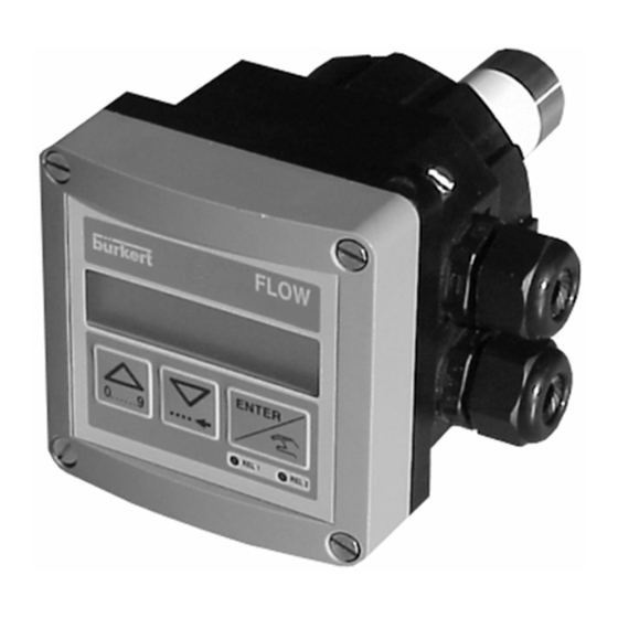
    INFORMATION 6.3 CONSTRUCTION ET PRINCIPE DE MESURE Construction Le transmetteur de débit 8045 rassemble un capteur et un transmetteur avec affichage dans un boîtier en polycarbonate IP65. La base du doigt du capteur contient un électro-aimant et 2 électrodes en contact avec le fluide afin de détecter la tension induite.
  • Page 136: Annexe

    ANNEXE 6.4 RÉFÉRENCES DE COMMANDE Version Transmetteur de débit électromagnétique 8045 Type universel (standard); connexion par presse-étoupe sortie 4-20 mA; sortie impulsion; 2 totalisateurs Alimentation Relais Boîtier Joints Capteur Code Ident. 18-36 VDC Court, PVDF 426498 18-36 VDC Long, PVDF...
  • Page 137: Livraison Standard

    1 transmetteur de débit électromagnétique 8045 1 manuel d‘utilisation en 3 langues 1 manuel d‘utilisation des raccords S020/1500/1501 1 obturateur de presse-étoupe, pour un 8045 avec doigt en acier inoxydable (Lorsque le transmetteur est avec option relais, 1 joint multi-passage est également livré).
  • Page 138: Pièces De Rechange

    Capteur PVDF, version longue pour DN >100 (> 4") 444781 Capteur inox, version longue pour DN >100 (> 4") 449760 Kit d‘étanchéité FPM 425554 Kit d‘étanchéité EPDM 425555 Kit d‘étanchéité EPDM (FDA) 449761 Manuel d‘utilisation des raccords S020/1500/1501 429633 8045 Fluid Control Systems...
  • Page 139 électrodes soit perpendiculaire à la flèche sur le côté du boîtier (voir 3.2) resserrer la vis de maintien du capteur. Fig. 6.1 Vue éclatée du transmetteur de débit électromagnétique 8045 8045 Fluid Control Systems...
  • Page 140 0.3 0.5 10 m/s Vitesse EXEMPLE: Spécifications: Débit nominal: 10 m Détermination avec une vitesse optimale du fluide : 2-3 m/s Avec ces caractéristiques, le diamètre du raccord le mieux approprié d‘après l‘abaque est le DN40 8045 Fluid Control Systems...
  • Page 141 0.02 0.01 0.3 0.5 Vitesse EXEMPLE: Spécifications: Débit nominal: 50gpm Détermination avec une vitesse optimale du fluide : 8 fps Avec ces caractéristiques, le diamètre du raccord le mieux approprié d‘après l‘abaque est de 1 1/2“. 8045 Fluid Control Systems...
  • Page 142 ANNEXE 8045 Fluid Control Systems...
  • Page 143 SERVICE Australia Burkert Fluid Control Systems Bürkert Contromatic Niederlassung Dresden Unit 1 No.2, Welder Road China/HK Ltd. Christian Bürkert Straße 2 Seven Hills NSW 2147 Guangzhou Representative Office D-01900 Großröhrsdorf Tel +61 (2) 983 948 00 Rm. 1305, Tower 2...
  • Page 144 Tel +48 22 840 60 10 Fax +48 22 840 60 11 Turkey Bürkert Contromatik Singapore Akiskan Kontrol Sistemleri Ticaret Burkert Contromatic Singapore Pte.Ltd. No.11 Playfair Road 1203/8 Sok. No. 2-E Singapore 367986 Yenisehir Tel +65 383 26 12 Izmir...

Ce manuel est également adapté pour:

426532

Table des Matières