Chapitres
Table des Matières

Manuels Connexes pour Amann Girrbach Ceramill Motion


Sommaire des Matières pour Amann Girrbach Ceramill Motion
- Page 1 _ Bedienungsanleitung _ User Manual _ Mode d‘emploi _ Instrzioni d‘uso _ Modo de empleo _ Deutsch 2 - 23 _ English 24 - 45 _ Français 46 - 67 _ Italiano 68 - 89 _ Español 90 - 111...
-
Page 2: Table Des Matières
Wartungseinheit ....8 Installation der Software Ceramill Match und Ceramill Motion ..10 Herstellen der Netzwerkverbindung 11 Inbetriebnahme der Ceramill Motion 11 Anwendung und Bedienung . -
Page 3: D E
S Y M B O L E R K L Ä R U N G Symbolerklärung Warnhinweise Weitere Symbole in der Anleitung Warnhinweise im Text werden mit einem Symbol Bedeutung farbig hinterlegten Warndreieck gekenn- ▷ Punkt einer Handlungsbeschreibung zeichnet und umrandet. Punkt einer Liste Bei Gefahren durch Strom wird das Ausru- ▪... -
Page 4: Allgemeine Sicherheitshinweise
A L L G E M E I N E S I C H E R H E I T S H I N W E I S E Allgemeine Sicherheits- Geeignetes Personal hinweise HINWEIS: Bei der Aufstellung, Inbetriebnahme und Benut- Das Gerät darf nur von geschultem Fachperso- zung des Geräts sind stets die folgenden Sicher- nal in Betrieb genommen und bedient werden. -
Page 5: Angaben Zum Gerät
A N G A B E N Z U M G E R Ä T Angaben zum Gerät Lieferumfang Bestimmungsgemäßer Gebrauch _ Fräsgerät Ceramill Motion Die Ceramill Motion ist ein PC-gesteuertes Fräsge- _ Netzkabel rät zur Herstellung von Zahnersatz durch Fräsen _ USB-Kabel (5 m) von Rohlingen aus vorgesintertem Zirkonoxid, _ Netzwerkkabel (5 m) Kunststoffen und Wachs. -
Page 6: Bauteile Und Schnittstellen
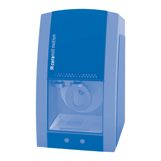
A N G A B E N Z U M G E R Ä T Bauteile und Schnittstellen Bild 1 Geräteübersicht Frontseite 1 Messvorrichtung Werkzeuglänge 2 Werkzeughalter 3 Frässpindel 4 Rohlingshalterung 5 Staubschale 6 Servicetaste 7 Bedientaste... - Page 7 A N G A B E N Z U M G E R Ä T Bild 2 Geräteübersicht Rückseite 1 USB-Anschluss 11 Schublade mit Sicherungen 2 Netzwerkanschluss 12 Netzanschluss 3 Programmierschnittstelle RS 232 13 Hauptschalter 4 Steckplatz SD-Karten 5 Buchse für Steuerungskabel der Absaugung (für Automatikbetrieb) 6 Druckluftschlauch 250 mm 7 Drucklufteingang...
-
Page 8: Installation
I N S T A L L A T I O N Installation Aufstellung Wartungseinheit _ Das Gerät ist ausschließlich zur Benutzung Die Jäger-Spindel ist mit einer Sperrluft-Einrich- innerhalb trockener, geschlossener Räume tung ausgestattet. Diese Sperrluft verhindert, bestimmt. dass Späne und Staub in die Spindel gelangen kön- _ Der minimale Platzbedarf für die Ceramill nen. - Page 9 I N S T A L L A T I O N Anbringen der Wartungseinheit Anforderungen Kompressor Der Kompressor für die Ceramill Motion muss fol- gende Mindestanforderungen erfüllen: _ Eingangsvolumenstrom: 100 l/min (3,54 CFM) _ Behältervolumen: min. 50 l (13,2 Gallons) _ Ausgangsdruck: 8 bar / 116 psi _ Schalldruckpegel: max.
-
Page 10: Installation Der Software Ceramill Match Und Ceramill Motion
HINWEIS: der Installationsanleitung. Fehlfunktionen durch Treiber-Konflikte auf dem PC. ▷ Das PDF-Dokument öffnen und den Anwei- ▷ Fräsgerät Ceramill Motion und Ceramill Match sungen in der Anleitung folgen. Dongle erst nach der Installation der Software Verbinden der Schnittstellen mit dem PC verbinden. -
Page 11: Herstellen Der Netzwerkverbindung
PC bzw. dem Netzwerk über ein Netz- sprechende Schwesterwerkzeug zu werkkabel verbinden. ▷ Die Standardwerkzeuge Ceramill Motion Roto in Die maximal zulässige Länge der Netzwerk-Lei- den Werkzeughalter der Ceramill Motion einste- tung zum PC bzw. zum Netzwerk-Router beträgt cken. - Page 12 I N S T A L L A T I O N ▷ Den gewünschten Rohling in die Aufnahme der ▷ Die Tür des Fräsgeräts schließen. ▷ Das Fräsgerät am Hauptschalter [4] einschal- Ceramill Motion einsetzen. Die hohe/dicke Seite des Rohlings muss zur Spindel zeigen. ten. ▷ Den PC einschalten.
-
Page 13: Anwendung Und Bedienung
A N W E N D U N G U N D B E D I E N U N G Anwendung und Bedienung Überprüfen des Modellbereichs WARNUNG: Der Modellbereich, auf dem die Arbeit gefertigt Gefahr durch weggeschleuderte Späne oder werden soll, muss in die Kontur der beiliegenden Werkzeugbruchstücke! Schablone passen (siehe auch Match Package). -
Page 14: Funktion Der Tasten
Das Programm wird unterbrochen. Bedientaste Tasten auch über die Software ausgelöst [A] blinkt. werden (siehe Anleitung zur Software Um das Programm fortzusetzen: Ceramill Motion). ▷ Bedientaste [A] kurz drücken. -oder- Referenzfahrt ▷ Tür schließen und Bedientaste [A] kurz drücken. Nach dem Einschalten müssen mit einer Referenz-... -
Page 15: Kontrolle Des Werkstücks Während Eines Laufenden Programms
A N W E N D U N G U N D B E D I E N U N G Kontrolle des Werkstücks während Anfahren der Werkzeugwechselpo- eines laufenden Programms sition ▷ Bedientaste [A] länger als drei Sekunden Die Werkzeugwechselposition kann von der drücken. -
Page 16: Registrierung Und Downloadinfos
Scanner (Ceramill Map) Rückseite des Geräts Gehäuseober- seite des PCs Mind Dongle Software- schachtel [4] Motion (Ceramill Motion) Rückseite des Geräts [5] Match Dongle Software- schachtel Tab. 4 ▷ Die Registrierung erfolgt unter ▷ Die Nutzungsbedingungen akzeptieren. ▷ Den Button „Konto jetzt erstellen“ anklicken. -
Page 17: Auftragstracking M-Center
R E G I S T R I E R U N G U N D D O W N L O A D I N F O S Innerhalb von 24 Stunden wird eine weitere E-Mail Downloadinfos verschickt. Sie enthält die Bestätigung der Regis- Die weiteren Anleitungen zur Bedienung (Videotu- trierung und die FTP-Zugangsdaten (6-stellig) für torials) des Scanners Ceramill Map und der Soft-... -
Page 18: Reinigung Und Wartung
R E I N I G U N G U N D W A R T U N G Reinigung und Wartung Reinigung Wöchentliche Wartung Das Fräsgerät muss nach jedem Arbeitstag gerei- HINWEIS: nigt werden. Gefahr von Geräteschäden! Um eine Reinigung der Fräskammer und der Spin- ▷... - Page 19 R E I N I G U N G U N D W A R T U N G Um eine Reinigung der Spindel durchzuführen: Um die Spannzange zu entnehmen: ▷ Servicetaste [B] kurz drücken. ▷ Den schwarzen Spindelschlüssel [5] auf die Das aktuelle Werkzeug wird abgelegt und die Zange stecken.
- Page 20 R E I N I G U N G U N D W A R T U N G ▷ Die Spannzange von innen mit der feinen Wenn das Werkzeug aus dem Werkzeughalter der Zangenbürste [2] reinigen. Ceramill Motion stammt: ▷ Das Werkzeug wieder lagerichtig im Werkzeug- halter platzieren. ▷ Die Tür des Fräsgeräts schließen.
-
Page 21: Monatliche Wartung
R E I N I G U N G U N D W A R T U N G Monatliche Wartung Externe Wartung Nach 1500 Betriebsstunden ist eine externe War- Nullpunktüberprüfung tung notwendig. Die Software der Ceramill Motion Es wird empfohlen, einmal monatlich eine Null- zeigt eine entsprechende Meldung. punktüberprüfung durchzuführen. ▷ Mit dem Ceramill-Helpdesk Kontakt aufnehmen ▷... -
Page 22: Störungen, Reparaturen Und Gewährleistung
S T Ö R U N G E N , R E P A R A T U R E N U N D G E W Ä H R L E I S T U N G Störungen, Reparaturen Umweltschutz und Gewährleistung Verpackung... -
Page 23: Technische Daten Und Ersatzteile
T E C H N I S C H E D A T E N U N D E R S A T Z T E I L E Technische Daten und Ersatzteile Ersatzteile Änderungen vorbehalten. Art.Nr.: Bezeichnung Technische Daten Ceramill Motion 179210 Wartungseinheit Motion 179211 Schraubenset Einheit... - Page 24 Service Unit ....30 Installation of the Ceramill Match and Ceramill Motion Software ..32 Establishing the Network Connection .
-
Page 25: E N
E X P L A N A T I O N O F S Y M B O L S Explanation of Symbols Warning indications Other symbols on the machine Warning indications in the text are marked Symbol Meaning with a colour-backed triangle and boxed. USB port (socket type B) In case of hazards through electricity, the exclamation mark in the warning triangle... -
Page 26: General Safety Instructions
G E N E R A L S A F E T Y I N S T R U C T I O N S General Safety Instruc- Suitable Personnel tions NOTE: When installing, starting-up and operating the Starting-up and operation of the machine may machine, always observe the following safety only be carried out by trained specialised per- instructions:... -
Page 27: Machine Specifications
The product's Declaration of Conformity can be _ Extractor adapter viewed under www.amanngirrbach.com. The Ceramill Motion is delivered with a Ceramill TEST 71L test blank (Order No. 760301) inserted in the blank holder. Prior to delivery, a test object was factory-milled in order to check the zero point settings. -
Page 28: Components And Interfaces
M A C H I N E S P E C I F I C A T I O N S Components and Interfaces Fig. 1 Machine overview, front 1 Measuring device, tool length 2 Tool holder 3 Milling spindle 4 Blank holder 5 Dust tray 6 Service button... - Page 29 M A C H I N E S P E C I F I C A T I O N S Fig. 2 Machine overview, rear 1 USB port 11 Fuse compartment 2 Network connection 12 Power supply connection 3 Programming interface RS 232 13 Main switch 4 SD card slot 5 Socket for control cable, extraction (for auto-...
-
Page 30: Installation
I N S T A L L A T I O N Installation Setting Up Service Unit _ The machine is intended exclusively for use The Jäger spindle is equipped with a sealing-air within dry, closed rooms. feature. This sealing air prevents shavings/chips _ Minimum space requirements for the Ceramill and dust from entering the spindle. - Page 31 I N S T A L L A T I O N Installing the service unit Compressor requirements The compressor for the Ceramill Motion must meet the following minimum requirements: _ Inlet flow rate: 100 l/min (3.54 CFM) _ Compressed-air reservoir: min. 50 l (13.2 gallons)
-
Page 32: Installation Of The Ceramill Match And Ceramill Motion Software
Connecting the interfaces NOTE: Malfunctions caused by driver conflicts on the ▷ Do not connect the Ceramill Motion milling machine and the Ceramill-Match-Dongle to the PC until after the software is installed. ▷ Connect a USB cable to the USB data port [1] of the milling machine and to a free USB port of Fig. -
Page 33: Establishing The Network
Fig. 5 Ceramill-Match-Dongle ▷ Insert the Ceramill Motion Roto standard tools Establishing the Network Connec- into the tool holder of the Ceramill Motion. Posi- tion tion the tool shank facing toward the outside. ▪ Roto 2.5 is in the spindle. - Page 34 ▷ Insert the selected blank into the holder in the ▷ Shut the milling machine door. ▷ Switch the milling machine on via the main Ceramill Motion. The high/thick side of the blank must face the spindle. switch [4]. ▷ Switch the PC on.
-
Page 35: Application And Operation
A P P L I C A T I O N A N D O P E R A T I O N Application and Operation Checking the Model Area WARNING: The model area, on which the work is to be Danger from shavings/chips or tool fragments machined, must fit within the contour of the being thrown from the machine! -
Page 36: Function Of The Buttons
▷ Briefly push operation button [A]. Instead of with the buttons, these func- -or- ▷ Open the door. tions can also be actuated via the software (see instructions of the Ceramill Motion The program is stopped. Operation button [A] Software). flashes. To continue the program: Reference Run ▷... -
Page 37: Checking The Workpiece During A Running Program
A P P L I C A T I O N A N D O P E R A T I O N Checking the Workpiece During a Moving the the Tool-changing Posi- Running Program tion ▷ Push operation button [A] for at least three sec- The tool-changing position can be moved to from onds. -
Page 38: Registration And Download
Rear side of the unit Top of PC housing Mind Dongle Software box [4] Motion (Ceramill Motion) Rear side of the unit [5] Match Dongle Software box Tab. 4 ▷ To register, log on to ▷ Accept the terms of use. -
Page 39: Order Tracking, M-Center
R E G I S T R A T I O N A N D D O W N L O A D I N F O R M A T I O N Within the next 24 hours you will receive another Download Infos E-mail. -
Page 40: Cleaning And Maintenance
C L E A N I N G A N D M A I N T E N A N C E Cleaning and Maintenance Cleaning Weekly Maintenance The milling machine must be cleaned after each NOTE: working day. Danger of damaging the machine! In order to clean the milling chamber and the spin- ▷... - Page 41 C L E A N I N G A N D M A I N T E N A N C E In order to clean the spindle: To remove the collet: ▷ Briefly push service button [B]. ▷ Apply the black spindle wrench [5] over the col- The current tool is placed down and the spindle let.
- Page 42 C L E A N I N G A N D M A I N T E N A N C E ▷ Clean the inside of the collet with the fine collet When the milling tool was from the Ceramill brush [2].
-
Page 43: Monthly Maintenance
▪ Austria: +43 5523 62333 390 The test blank is to be used exclusively for test ▪ International: +43 5523 62333 399 milling and calibration of the Ceramill Motion. The ▪ helpdesk@amanngirrbach.com corresponding instructions are on the Ceramill Match CD or available on our website under www.ceramill-m-center.com... -
Page 44: Malfunctions, Repairs And Warranty
M A L F U N C T I O N S , R E P A I R S A N D W A R R A N T Y Malfunctions, Repairs and Environmental Protection Warranty Packaging Malfunctions In terms of packaging, AmannGirbach participates in country-specific recycling systems, which In case of malfunctions: ensure optimal recycling. -
Page 45: Technical Data And Spare Parts
T E C H N I C A L D A T A A N D S P A R E P A R T S Technical Data and Spare Parts Spare parts Subject to changes. Art. No.: Designation Technical Data - Ceramill Motion 179210 Service unit, Motion 179211 Screw set for blank holder, Motion Unit... - Page 46 ..... . 67 Installation du logiciel Ceramill Match et Ceramill Motion ..54 Connexion au réseau ... . 55 Mise en service de Ceramill Motion 55 Application et utilisation .
-
Page 47: F R
E X P L I C A T I O N D E S S Y M B O L E S Explication des symboles Mises en garde Autres symboles dans le mode d’emploi Les mises en garde dans le texte sont indi- Symbole Signification quées dans un panneau d’avertissement... -
Page 48: Consignes Générales De Sécurité
C O N S I G N E S G É N É R A L E S D E S É C U R I T É Consignes générales de Personnel approprié sécurité AVERTISSEMENT : Respectez les consignes de sécurité suivantes lors Cet appareil ne doit être mis en service et utilisé... -
Page 49: Données Relatives À L'appareil
Données relatives à l’appareil Contenu de la livraison Utilisation conforme _ Appareil de fraisage Ceramill Motion Ceramill Motion est une machine de fraisage de _ Câble d’alimentation commande numérique par ordinateur pour la _ Câble USB (5 m) fabrication de prothèse dentaire par fraisage de _ Câble réseau (5 m) -
Page 50: Composants Et Interfaces
D O N N É E S R E L A T I V E S À L ’ A P P A R E I L Composants et interfaces Fig. 1 Vue d’ensemble de l’appareil face avant 1 Dispositif de mesure de longueur de l’outil 2 Porte-outils 3 Broche 4 Support pour pièce brute... - Page 51 D O N N É E S R E L A T I V E S À L ’ A P P A R E I L Fig. 2 Vue d’ensemble de l’appareil face arrière 1 Prise USB 10 Branchement du tuyau d’aspiration 2 Connexion secteur 11 Tiroir avec fusibles 3 Interface de programmation RS 232...
-
Page 52: Installation
_ La place min. nécessaire pour l’installation de et de poussières dans la broche. L’unité d’entre- Ceramill Motion y compris les connexions est de : tien filtre les impuretés éventuelles contenues ▪ Largeur : 615 mm dans l’air de barrage et prévient ainsi de graves... - Page 53 I N S T A L L A T I O N Montage de l’unité d’entretien Exigences compresseur Le compresseur de Ceramill Motion doit remplir les exigences minimales suivantes : _ débit d’air à l’entrée : 100 l/min (3,54 CFM) _ volume du réservoir : 50 l (13,2 gallons) min.
-
Page 54: Installation Du Logiciel Ceramill Match Et Ceramill Motion
Connecter les interfaces les pilotes. ▷ Ne raccordez la clé électrique de la fraiseuse Ceramill Motion et Ceramill Match au PC qu’après l’installation du logiciel. ▷ A l’aide du câble USB, reliez l’interface USB [1] de la fraiseuse à une douille USB libre du PC. -
Page 55: Connexion Au Réseau
Ceramill Motion saisit l’outil frère approprié. ▷ Reliez l’interface Ethernet [2] de la fraiseuse au ▷ Placez les outils standards Ceramill Motion Roto PC ou au réseau via un câble réseau. dans le porte-outils de Ceramill Motion. Posi- La longueur maximale admissible de la ligne de tionnez la queue d’outil vers l’extérieur. - Page 56 ▷ Placez la pièce brute souhaitée dans le récep- ▷ Fermez la porte de la fraiseuse. ▷ Allumez la fraiseuse via l’interrupteur principal teur de Ceramill Motion. Le côté haut/épais de la pièce brute doit être orienté vers la broche. [4].
-
Page 57: Application Et Utilisation
A P P L I C A T I O N E T U T I L I S A T I O N Application et utilisation Contrôle de la zone du modèle MISE EN GARDE : Vérifiez si la zone du modèle sur laquelle le travail Danger dû... -
Page 58: Fonction Des Touches
[A] s’allume. Ces fonctions peuvent également être action- nées à partir du logiciel (cf. instructions d’uti- Pour interrompre le programme : lisation du logiciel Ceramill Motion). ▷ Appuyez brièvement sur la touche de com- mande [A]. Prise de référence -ou- ▷... -
Page 59: Contrôle De La Pièce À Travailler Pendant Un Programme En Cours
A P P L I C A T I O N E T U T I L I S A T I O N ▷ Appuyez brièvement sur la touche d’entretien [B]. Le programme est immédiatement relancé à l’endroit où il a été interrompu. La touche de L’outil actuel est déposé... -
Page 60: Informations Sur L'inscription Et Le Téléchargement
Dos de l’appa- reil Face supérieu- re du carter du Clé électronique Mind Boîte de logi- ciel [4] Motion (Ceramill Motion) Dos de l’appa- reil [5] Clé électronique Match Boîte de logi- ciel Tab. 4 ▷ L’inscription s’effectue sous ▷ Acceptez les conditions d’utilisation. -
Page 61: Suivi De L'ordre Au Centre M
I N F O R M A T I O N S S U R L ’ I N S C R I P T I O N E T L E T É L É - Dans les 24 heures suivantes vous recevrez un Informations sur les télécharge- courriel contenant la confirmation de votre ins- ments... -
Page 62: Nettoyage Et Entretien
N E T T O Y A G E E T E N T R E T I E N Nettoyage et entretien Nettoyage Entretien hebdomadaire La fraiseuse doit être nettoyée après chaque jour- AVERTISSEMENT : née de travail. Danger d’endommagement de l’appareil ! Pour effectuer le nettoyage de la chambre de frai- ▷... - Page 63 N E T T O Y A G E E T E N T R E T I E N Pour nettoyer la broche : Pour pouvoir ôter la pince de serrage : ▷ Appuyez brièvement sur la touche d’entretien ▷...
- Page 64 N E T T O Y A G E E T E N T R E T I E N ▷ Nettoyez la pince de serrage de l’intérieur avec Si l’outil provient du porte-outils de Ceramill la brosse à griffes fine [2]. Motion : ▷...
-
Page 65: Entretien Mensuel
Vérification du point zéro externe de l’appareil après 1500 heures de fonc- Il est recommandé d’effectuer une fois par mois tionnement. Le logiciel de Ceramill Motion affiche une vérification du point zéro. un message correspondant. ▷ Fraisez un cube d’essai provenant de la pièce ▷... -
Page 66: Dysfonctionnements, Réparations Et
D Y S F O N C T I O N N E M E N T S , R É P A R A T I O N S E T G A R A N T I E Dysfonctionnements, Protection de l’environne- réparations et garantie... -
Page 67: Caractéristiques Techniques Et Pièces De Rechange
C A R A C T É R I S T I Q U E S T E C H N I Q U E S E T P I È C E S D E R E - Caractéristiques techniques et pièces de rechange Pièces de rechange Sous réserve de modifications. N° d’arti- Caractéristiques techniques Ceramill Motion cle : Désignation 179210 Unité d’entretien Motion Unité... - Page 68 Unità di servizio ....74 Installazione dei software Ceramill Match e Ceramill Motion ..76 10 Protezione dell'ambiente ... 88 Creazione del collegamento alla rete .
-
Page 69: I T
S P I E G A Z I O N E D E I S I M B O L I Spiegazione dei simboli Indicazioni di avvertimento Ulteriori simboli nelle istruzioni d'uso Nel testo le indicazioni di avvertimento Simbolo Significato sono contrassegnate da un triangolo di ▷... -
Page 70: Indicazioni Generali Di Sicurezza
I N D I C A Z I O N I G E N E R A L I D I S I C U R E Z Z A Indicazioni generali di Personale adatto sicurezza INDICAZIONE: Durante l'installazione, la messa in funzione e L'apparecchio deve essere messo in funzione ed l'uso dell'apparecchio devono sempre essere utilizzato esclusivamente da personale specializ-... -
Page 71: Dati Relativi All'apparecchio
Dati relativi all'apparecchio Volume di fornitura Uso conforme a destinazione _ Fresatore Ceramill Motion Ceramill Motion è un fresatore comandato da PC _ Cavo di alimentazione per la realizzazione di denti sostitutivi tramite la _ Cavo USB (5 m) fresatura di grezzi in ossido di zirconio, resine e _ Cavo di rete (5 m) cera. -
Page 72: Componenti Ed Interfacce
D A T I R E L A T I V I A L L ' A P P A R E C C H I O Componenti ed interfacce Fig. 1 Vista generale dell'apparecchio - lato anteriore 1 Dispositivo di misura lunghezza utensile 2 Portautensili 3 Mandrino portafresa 4 Supporto del grezzo... - Page 73 D A T I R E L A T I V I A L L ' A P P A R E C C H I O Fig. 2 Vista generale dell'apparecchio - lato posteriore 1 Collegamento USB 10 Attacco tubo di aspirazione 2 Collegamento alla rete 11 Cassetto con fusibili 3 Interfaccia di programmazione RS 232...
-
Page 74: Installazione
Il mandrino Jäger è dotato di un dispositivo aria di l'utilizzo in locali chiusi ed asciutti. tenuta. Questa aria di tenuta impedisce che tru- _ L'ingombro minimo per Ceramill Motion, colle- cioli e polvere possano penetrare nel mandrino. gamenti inclusi, è di: L'unità... - Page 75 I N S T A L L A Z I O N E Applicazione dell'unità di servizio Requisiti compressore Il compressore per Ceramill Motion deve soddi- sfare i seguenti requisiti minimi: _ Portata di entrata: 100 l/min (3,54 CFM) _ Volume del serbatoio: min. 50 l (13,2 galloni) _ Pressione di uscita 8 bar / 116 psi _ Livello di pressione acustica: max.
-
Page 76: Installazione Dei Software Ceramill Match E Ceramill Motion
▷ Aprire il documento PDF e seguire le istruzioni Funzionamenti difettosi a causa di conflitti di dri- contenute nel documento stesso. ver sul PC. ▷ Collegare al PC il fresatore Ceramill Motion ed Collegamento delle interfacce il dongle Ceramill Match solamente dopo l'installazione del software. -
Page 77: Creazione Del Collegamento Alla
I N S T A L L A Z I O N E ▷ Inserire gli utensili standard Ceramill Motion Creazione del collegamento alla Roto nel portautensili del Ceramill Motion. Effet- rete tuando l'inserimento posizionare lo stelo degli utensili verso l'esterno. - Page 78 Motion. Il lato alto/spesso del grezzo deve essere rivolto verso il mandrino. [4]. ▷ Accendere il PC. ▷ Avviare il software Ceramill Motion. All'avvio del software avviene un'inizializza- zione dell'apparecchio. Se il fresatore non viene rilevato: ▷ effettuare un riavvio del PC.
-
Page 79: Impiego Ed Uso
I M P I E G O E D U S O Impiego ed uso Controllo del settore del modello ATTENZIONE: Il settore del modello su cui deve essere eseguito Pericolo a causa di trucioli oppure frammenti di il lavoro deve rientrare nel profilo della sagoma utensile scagliati. -
Page 80: Funzione Dei Tasti
I M P I E G O E D U S O Funzione dei tasti Per avviare il funzionamento di riferimento: ▷ Premere brevemente il tasto di comando [A]. Il funzionamento di riferimento viene avviato. Tasto di comando [A] lampeggia. Il funzionamento di riferimento può... -
Page 81: Controllo Del Pezzo In Lavorazione Durante Un Programma In Corso
I M P I E G O E D U S O ▷ Chiudere la porta e premere brevemente il tasto ▷ Premere brevemente il tasto di servizio [B]. di comando [A]. L'utensile attuale viene deposto ed il mandrino Il programma prosegue dal punto in cui è stato si porta nella posizione di servizio. -
Page 82: Registrazione Ed Informazioni Per Il
Lato poste- riore dell'appa- recchio Lato superiore della copertura Dongle Mind Scatola del sof- tware [4] Motion (Ceramill Motion) Lato poste- riore dell'appa- recchio [5] Dongle Match Scatola del sof- tware Tab. 4 ▷ La registrazione avviene alla pagina ▷ Cliccare il pulsante «Crea account». -
Page 83: Tracking Ordini M-Center
R E G I S T R A Z I O N E E D I N F O R M A Z I O N I P E R I L D O W N L O A D L'indirizzo e-mail e la password scelta sono i dati Informazioni per il download www.cera-... -
Page 84: Pulizia A Manutenzione
P U L I Z I A A M A N U T E N Z I O N E Pulizia a manutenzione Pulizia Manutenzione settimanale Il fresatore deve essere pulito dopo ogni giorno di INDICAZIONE: lavoro. Pericolo di danni all'apparecchio! Per effettuare la pulizia della camera di fresatura ▷... - Page 85 P U L I Z I A A M A N U T E N Z I O N E Per effettuare la pulizia del mandrino: Per togliere la pinza di fissaggio: ▷ Premere brevemente il tasto di servizio [B]. ▷...
- Page 86 P U L I Z I A A M A N U T E N Z I O N E ▷ Pulire l'interno della pinza di fissaggio con la Se l'utensile proviene dal portautensili del Cera- spazzola per pinza sottile [2]. mill Motion: ▷...
-
Page 87: Manutenzione Mensile
P U L I Z I A A M A N U T E N Z I O N E Manutenzione mensile Manutenzione esterna Dopo 1500 ore d'esercizio si rende necessaria una Controllo dei punti zero manutenzione esterna. Il software del Ceramill Si consiglia di effettuare una volta al mese un con- Motion visualizza una relativa segnalazione. -
Page 88: Anomalie, Riparazioni E Garanzia
A N O M A L I E , R I P A R A Z I O N I E G A R A N Z I A Anomalie, riparazioni e Protezione dell'ambiente garanzia Imballo Anomalie Per quanto riguarda l'imballo AmannGirrbach rispetta i sistemi di riciclo specifici del paese di In caso di anomalie: impiego che garantiscono un riciclo ottimale. -
Page 89: Dati Tecnici E Parti Di Ricambio
D A T I T E C N I C I E P A R T I D I R I C A M B I O Dati tecnici e parti di ricambio Parti di ricambio Con riserva di modifiche. No. Art.: Denominazione Dati tecnici Ceramill Motion 179210 Unità di servizio Motion 179211 Set di viti supporto grezzo Motion Unità... - Page 90 Unidad de tratamiento ..96 Instalación del software Ceramill Match y Ceramill Motion ..98 Conexión a la red informática ..99 Puesta en marcha de la Ceramill Motion .
-
Page 91: Simbología Empleada
S I M B O L O G Í A E M P L E A D A Simbología empleada Advertencias de peligro Símbolos adicionales en el manual Las advertencias de peligro se identifican Símbolo Significado con un triángulo de señalización sobre ▷... -
Page 92: Instrucciones De Seguridad Generales
I N S T R U C C I O N E S D E S E G U R I D A D G E N E R A L E S Instrucciones de seguri- Aptitud del personal dad generales OBSERVACIO?N: Al instalar, poner en marcha, o utilizar el aparato El aparato solamente se deberá... -
Page 93: Datos Sobre El Aparato
La declaración de conformidad del producto _ Adaptador para aspiración puede consultarse en www.amanngirrbach.com. La Ceramill Motion se surte con la pieza en bruto para pruebas Ceramill TEST 71L (nº de pedido 760301) montada en el soporte de la misma. El aparato se suministra de fábrica con una probeta... -
Page 94: Componentes, Puertos E
D A T O S S O B R E E L A P A R A T O Componentes, puertos e interfases Fig. 1 Componentes frontales del aparato 1 Dispositivo de medición de longitud de la herra- mienta 2 Portaherramientas 3 Husillo de fresar 4 Soporte de la pieza en bruto 5 Bandeja recogepolvo... - Page 95 D A T O S S O B R E E L A P A R A T O Fig. 2 Componentes dorsales del aparato 1 Puerto USB 10 Conexión para manguera de aspiración 2 Puerto de red red informática 11 Cajetín de fusibles 3 Interfaz de programación RS 232 12 Conexión a la red...
-
Page 96: Instalación
I N S T A L A C I Ó N Instalación Colocación Unidad de tratamiento _ El aparato ha sido diseñado para su uso exclu- El husillo Jäger incorpora un dispositivo de obtu- sivo en locales cerrados y secos. ración por aire. - Page 97 I N S T A L A C I Ó N Fijación de la unidad de tratamiento Prestaciones del compresor El compresor de la Ceramill Motion deberá satisfa- cer las siguientes prestaciones mínimas: _ Caudal de entrada: 100 l/min (3,54 CFM) _ Capacidad del depósito: mín.
-
Page 98: Instalación Del Software Ceramill Match Y Ceramill Motion
▷ Conectar un extremo del cable de mando a la Instalación del software Ceramill interfaz de mando para aspiración [4] situada al Match y Ceramill Motion dorso de la fresadora, y su otro extremo al OBSERVACIO?N: dorso del dispositivo de aspiración (p. ej. Cera- mill Airstream). -
Page 99: Conexión A La Red Informática
▷ Opcional: Alojar las herramientas gemelas en el biar el tipo de conexión de USB a Ethernet, portaherramientas de la Ceramill Motion. Al rea- adaptando, si procede, la dirección IP (ver des- lizar esto cuidar que el mango quede orientado cripción del Software Ceramill Motion). - Page 100 ▷ Montar la pieza en bruto deseada en el aloja- ▷ Cerrar la puerta de la fresadora. ▷ Conectar la fresadora con el interruptor princi- miento de la Ceramill Motion. La cara alta/gruesa de la pieza en bruto deberá señalar pal [4].
-
Page 101: Utilización Y Manejo
U T I L I Z A C I Ó N Y M A N E J O Utilización y manejo Control del área que ocupa el ADVERTENCIA: modelo ¡Peligro por la proyección brusca de virutas o de El área ocupada por el modelo a fresar debe que- fragmentos en caso de rotura de la herramienta! dar dentro del contorno indicado en la plantilla ▷... -
Page 102: Función De Los Botones
U T I L I Z A C I Ó N Y M A N E J O ▷ Accionar brevemente el botón de manejo [A]. Función de los botones Comienza el recorrido de referenciado. El botón de manejo [A] parpadea. Es posible interrumpir el recorrido de referen- ciado en curso: ▷... -
Page 103: Control De La Pieza De Trabajo Durante Un Programa En Curso
U T I L I Z A C I Ó N Y M A N E J O ▷ Cerrar la puerta y apretar brevemente el botón ▷ Accionar brevemente el botón de servicio [B]. de manejo [A]. La herramienta actualmente en uso es deposi- El programa prosigue partiendo de la posición tada y el husillo se sitúa en la posición de servi- en la que se detuvo. -
Page 104: Registro E Información Para Descargas
Lado superior de la carcasa del PC Mind Dongle Caja del soft- ware [4] Motion (Ceramill Motion) Dorso del apa- rato [5] Match Dongle Caja del soft- ware Tab. 4 ▷ El registro se realiza bajo ▷ Aceptar las condiciones de uso. -
Page 105: Seguimiento De Pedidos M-Center
R E G I S T R O E I N F O R M A C I Ó N P A R A D E S C A R G A S Su dirección de correo electrónico y la contraseña Información para descarga que Ud. -
Page 106: Limpieza Y Mantenimiento
L I M P I E Z A Y M A N T E N I M I E N T O Limpieza y mantenimiento Limpieza Mantenimiento semanal La fresadora deberá limpiarse al final de cada jor- OBSERVACIO?N: nada. ¡Peligro de que se dañe el aparato! Para limpiar la cámara de fresado y el husillo: ▷... - Page 107 L I M P I E Z A Y M A N T E N I M I E N T O Para limpiar el husillo: Para desmontar la pinza de sujeción: ▷ Accionar brevemente el botón de servicio [B]. ▷...
- Page 108 ▷ Limpiar el interior de la pinza de sujeción con el Si la herramienta procede del portaherramientas cepillo fino para pinzas [2]. del Ceramill Motion: ▷ Alojar nuevamente la herramienta con su extremo orientado en posición correcta en el portaherramientas.
-
Page 109: Mantenimiento Mensual
Verificación del punto cero deberá realizarlo un servicio externo. El software Recomendamos un control mensual del punto de la Ceramill Motion emite el correspondiente cero. aviso al presentarse esta situación. ▷ Fresar un dado de prueba partiendo de la pieza ▷... -
Page 110: Fallos, Reparaciones Y Garantía
F A L L O S , R E P A R A C I O N E S Y G A R A N T Í A Fallos, reparaciones y Protección del medio garantía ambiente Embalaje Fallos AmannGirrbach colabora en el embalaje con los Si se presenta un fallo: sistemas de aprovechamiento específicos de cada ▷... -
Page 111: Datos Técnicos Y Piezas De Recambio
D A T O S T É C N I C O S Y P I E Z A S D E R E C A M B I O Datos técnicos y piezas de recambio Piezas de recambio Salvo modificación. Nº de art.: Denominación Datos técnicos Ceramill Motion 179210 Unidad de tratamiento Motion 179211 Kit de tornillos p. soporte de pieza en Unidad... - Page 112 Made in the European Union ISO 9001 Manufacturer | Hersteller Distribution | Vertrieb Distribution | Vertrieb D/A Amann Girrbach AG Amann Girrbach GmbH Herrschaftswiesen 1 Dürrenweg 40 austria@amanngirrbach.com 6842 Koblach | Austria 75177 Pforzheim | Germany germany@amanngirrbach.com Fon +43 5523 62333-0...