
Manuels Connexes pour Amann Girrbach ceramill argotherm 2


Sommaire des Matières pour Amann Girrbach ceramill argotherm 2
- Page 1 Betriebsanleitung 3- 33 User Manual 34- 64 Mode d‘emploi 65- 96 Instruzioni d‘uso 97- 129 Modo de empleo 130- 161...
-
Page 3: Table Des Matières
Angaben zum Gerät ....6 Ceramill Argotherm 2 ... . . 6 Programmübersicht Schnellwahl- tasten . -
Page 4: Symbolerklärung
S Y M B O L E R K L Ä R U N G Symbolerklärung Weitere Symbole in der Anleitung Warnhinweise Symbol Bedeutung ▷ Punkt einer Handlungsbeschreibung Warnhinweise im Text werden mit einem Warndreieck gekennzeichnet und umran- Punkt einer Liste det. -
Page 5: Allgemeine Sicherheitshinweise
A L L G E M E I N E S I C H E R H E I T S H I N W E I S E Allgemeine Sicherheitshinweise Bei der Aufstellung, Inbetriebnahme und Benut- HINWEIS: zung des Geräts sind stets die folgenden Sicher- ▷... -
Page 6: Angaben Zum Gerät
Betriebsverhalten den europäischen Richtlinien sowie den ergänzenden nationalen Anforde- 4.1.2 Bestimmungsgemäßer Gebrauch rungen. Die Konformität wurde mit der CE-Kenn- Ceramill Argotherm 2 ist ein Hochtemperaturofen zeichnung bestätigt. zum Sintern von gefrästen CoCrMo-Einheiten. Der EG-Richtlinien kompakte Ofen wird als Tischmodell eingesetzt. -
Page 7: Bauteile Und Schnittstellen
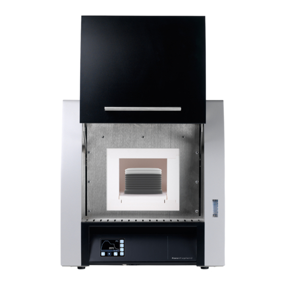
A N G A B E N Z U M G E R Ä T 4.1.4 Bauteile und Schnittstellen Bild 1 Geräteübersicht Frontseite 1 Abluftröhrchen 6 Einlegeplatte 2 Ofenhubtür 7 Kragenisolierung 3 Thermoelement 8 SD-Karten-Steckplatz 4 Heizstab 9 USB-Anschluss 5 Anzeige Schutzgasdurchfluss 10 Controller... - Page 8 A N G A B E N Z U M G E R Ä T Display Bedienebene 985°C 04h:15min Bild 2 Geräteübersicht Rückseite 1 Schutzgasanschluss Bild 3 Display Bedienebene 2 Netzschalter Schnellwahltasten Programm 1 ... 4 3 Netzanschluss Taste Programmstart 4 Sicherung Taste Programmstopp 5 Schaltanlagenentlüfter...
-
Page 9: Programmübersicht Schnellwahl
Das Display wechselt in die Bedienebene. Programmübersicht Schnellwahl- ▷ Um die Segmente des Programms anzuzeigen: tasten Taste drücken. Der Ceramill Argotherm 2 verfügt über ein fest hinterlegtes Programm zur Sinterung von Cera- mill Sintron. Programmbeschreibung _ Programm 1 [P1] ▪ Standardprogramm für Ceramill Sintron... -
Page 10: Ceramill Argovent
A N G A B E N Z U M G E R Ä T Ceramill Argovent 4.3.3 Bauteile und Schnittstellen 4.3.1 Lieferumfang _ Sinterkammer Ceramill Argovent (178710) ▪ Sinterbasis ▪ Sinterschale ▪ Sinterhaube ▪ Schutzgasretorte _ Sinterperlen Sintron _ Schalenzange Argovent ▷... -
Page 11: Installation
I N S T A L L A T I O N Installation ▷ Das Gerät auf einem schweren Arbeitstisch bzw. Aufstellung einer Werkbank auf eine nicht brennbare Unter- _ Das Gerät ist ausschließlich zur Benutzung lage aufstellen. innerhalb trockener, geschlossener Räume ▷... -
Page 12: Ofendeckel Demontieren
I N S T A L L A T I O N Ofendeckel demontieren GEFAHR: Stromschlag! ▷ Vor Öffnen des Gehäuses Netzstecker ziehen. Bild 6 Ofendeckel demontieren ▷ Vier Schrauben 2 mit Innensechskant-Schlüssel 1 Innensechskant-Schlüssel 2 Schraube 1 lösen. ▷ Deckel 3 abnehmen. 3 Deckel ▷... -
Page 13: Heizstäbe Montieren
I N S T A L L A T I O N Heizstäbe montieren ▷ Die Anschlusskontakte der Heizstäbe mit den HINWEIS: Verbindungsblechen verschrauben (Anzugsmo- Beschädigung der Heizstäbe! ment ca. 4 Nm). Die Heizstäbe sind extrem bruchempfindlich. ▷ Die Heizstäbe mit äußerster Vorsicht hand- haben! ▷... -
Page 14: Abluftröhrchen Montieren
I N S T A L L A T I O N ▷ Die Anschlusskabel mit den freien Kontakten Abluftröhrchen montieren der Heizstäbe verschrauben (Anzugsmoment ▷ Den Isolierstein Decke mit der Bohrung fluch- ca. 4 Nm). tend auf das Loch in der Decke der Ofenkammer setzen. -
Page 15: Ofendeckel Montieren
I N S T A L L A T I O N Ofendeckel montieren ▷ Erdungskabel 4 an der Deckelunterseite anste- ▷ Den Deckel mit vier Schrauben 2 fixieren. cken. ▷ Den Deckel 3 so auf die Oberseite des Ofens legen, dass die Bohrungen für die Verschrau- bung übereinander liegen. -
Page 16: Argovent Sinterbasis Einsetzen
I N S T A L L A T I O N Argovent Sinterbasis einsetzen ▷ Das Keramikrohr einsetzen. ▷ Das Schlauchstück der Argovent-Sinterbasis in ▷ Die Bodenplatte einlegen. das Keramikrohr an der Ofenrückwand einfä- deln und die Sinterbasis bis zum Anschlag in den Ofen schieben, ggf. - Page 17 I N S T A L L A T I O N ▷ Den Gasschlauch mit dem Push-In-Winkelstück ▷ Die Rückwand des Ofens aufsetzen und mit bis zum Anschlag auf das Schlauchstück der sechs Schrauben fixieren. Sinterbasis aufstecken, bis der Widerstand der Dichtung überwunden ist.
-
Page 18: Schutzgasanschluss
I N S T A L L A T I O N ▷ Das andere Ende des Gasschlauchs an der Gas- Schutzgasanschluss armatur der Schutzgasflasche anschließen. ▷ Die Gasarmatur an die Schutzgasflasche Dazu den Schutzgasschlauch durch Drehen und anschließen. Drücken in den Push-In Anschluss stecken, bis ▷... -
Page 19: Druckluftanschluss
I N S T A L L A T I O N Anforderungen zur Schutzgasversorgung Druckluftanschluss herstellen ▷ Druckluftschlauch an der Wartungseinheit bis Für den Betrieb muss das Schutzgas folgenden Mindestanforderungen genügen: zum Anschlag einstecken. _ Argon 4.6 (oder höher) aus handelsüblichen Fla- schen (vorzugsweise 20 l) _ Flaschendruck 200 bar/2900 psi Wenn der linke Manometerzeiger auf oder... -
Page 20: Elektrischer Anschluss
I N S T A L L A T I O N Elektrischer Anschluss ▷ Das andere Ende des Kabels an der Schutzkon- Der elektrische Anschluss erfolgt an einer Schutz- kontakt-Steckdose mit 220-240 V und 50-60 Hz. takt-Steckdose anschließen. Diese Steckdose muss sich in der Nähe des Ofens Der Austausch des Netzkabels darf nur gegen eine befinden und leicht zugänglich sein. -
Page 21: Anwendung Und Bedienung
A N W E N D U N G U N D B E D I E N U N G Anwendung und Bedienung Vor der produktiven Nutzung des Ofens muss ein Funktionstest durchgeführt werden: ▷ Ofenfunktion Schutzgas kontrollieren Vor Inbetriebnahme des Ofens sollte die- (siehe 6.1.1). - Page 22 A N W E N D U N G U N D B E D I E N U N G ▷ Mit der unteren schwarzen Regulierschraube Die richtige Schutzgasmenge muss vor dem ers- ten Programmdurchlauf sichergestellt werden. am Druckminderer auf exakt 1 bar nachregulie- Sie wird mit den Funktionen manuell ren.
- Page 23 A N W E N D U N G U N D B E D I E N U N G Um die Dichtigkeit des Argovents zu prüfen: 6.1.2 Kontrolle der Ofenfunktion Druckluft- ▷ Den Schutzgasaustritt (hinteres Loch) 1 der Sin- kühlung terbasis 2 bei laufendem Gasfluss mit dem Fin- WARNUNG:...
-
Page 24: Sintervorgang Starten
A N W E N D U N G U N D B E D I E N U N G ▷ Mit einem passenden Instrument einen Ring am Sintervorgang starten Rand ziehen, um dort die Perlenschicht zu redu- 6.2.1 Vorbereitung zum Sintern zieren. - Page 25 A N W E N D U N G U N D B E D I E N U N G ▷ Durch leichtes Drehen die Sinterhaube von den HINWEIS: darunter sitzenden Perlen freibewegen. Kippen oder Fallen der Sinterschale durch ihr hohes Gewicht.
- Page 26 A N W E N D U N G U N D B E D I E N U N G ▷ Die Schutzgasretorte mit der Schalenzange an ▷ Die Schutzgasretorte vorsichtig In die Ofen- den seitlichen Stiften aufnehmen. kammer einführen und drucklos über die Sinter- schale gleiten lassen.
- Page 27 A N W E N D U N G U N D B E D I E N U N G 6.2.2 Sintern HINWEIS: ▷ Die Ofentür schließen. Unzureichende Sinterergebnisse! ▷ Die Gasflasche aufdrehen. ▷ Die Schutzgasretorte mit der Schalenzange ▷...
-
Page 28: Sinterprogramm Abschließen
A N W E N D U N G U N D B E D I E N U N G ▷ Die Sinterschale mit der Schalenzange vorsich- Schutzgasdurchfluss einstellen tig aus der Ofenkammer nehmen und auf einer Während des Betriebs muss sich der dargestellte nicht brennbaren Unterlage absetzen. -
Page 29: Reinigung Und Wartung
R E I N I G U N G U N D W A R T U N G Reinigung und Wartung Ceramill Argotherm 2 7.1.2 Tägliche Kontrollen ▷ Die Anlage auf äußerlich erkennbare Schäden 7.1.1 Reinigung überprüfen. ▷ Die Funktion der Sicherheitseinrichtungen (z. B. -
Page 30: Ceramill Argovent
S T Ö R U N G E N , R E P A R A T U R E N U N D G E W Ä H R L E I S T U N G Störungen, Reparaturen Ceramill Argovent und Gewährleistung 7.2.1... -
Page 31: Gewährleistung
S T Ö R U N G E N , R E P A R A T U R E N U N D G E W Ä H R L E I S T U N G ▷ Den Ofendeckel montieren (siehe Seite 15). Thermoelement austauschen ▷... -
Page 32: Umweltschutz
U M W E L T S C H U T Z _ Betreiben der Anlage bei defekten Sicherheits- Umweltschutz einrichtungen oder nicht ordnungsgemäß ange- Verpackung brachten oder nicht funktionsfähigen Sicherheits- und Schutzvorrichtungen, Bei der Verpackung ist AmannGirrbach an den län- _ nicht Beachten der Hinweise in der Bedienungs- derspezifischen Verwertungssystemen beteiligt, anleitung bezüglich Transport, Lagerung, Mon-... -
Page 33: Technische Daten Und Zubehöre/Ersatzteile
T E C H N I S C H E D A T E N U N D Z U B E H Ö R E / E R S A T Z T E I L E Technische Daten und Zubehöre/Ersatzteile Zubehöre/Ersatzteile Art.Nr. - Page 34 Suitable Personnel ....36 Machine Specifications ... . . 37 Ceramill Argotherm 2 ... . 37 Program overview, shortcut keys . 40 Ceramill Argovent .
-
Page 35: E N
E X P L A N A T I O N O F S Y M B O L S Explanation of Symbols Other symbols in the Manual Warning indications Symbol Meaning ▷ Item of an operation description Warning indications in the text are marked with a triangle and boxed. -
Page 36: General Safety Instructions
G E N E R A L S A F E T Y I N S T R U C T I O N S General Safety Instruc- NOTE: tions ▷ Switch the machine off when not in use or When installing, starting-up and operating the unsupervised for longer periods, e.g., over- machine, always observe the following safety... -
Page 37: Machine Specifications
In terms of design and performance, this product 4.1.2 Intended Use complies with the European Directives and the Ceramill Argotherm 2 is a high-temperature fur- supplementary national requirements. Conform- nace for sintering milled CoCrMo units. The com- ity has been confirmed with the CE marking. -
Page 38: Components And Interfaces
M A C H I N E S P E C I F I C A T I O N S 4.1.4 Components and Interfaces Fig. 1 Machine overview, front 1 Exhaust air pipe 6 Insertion plate 2 Furnace lift door 7 Shroud insulation 3 Thermoelement 8 SD card slot... - Page 39 M A C H I N E S P E C I F I C A T I O N S Display, operating level 985°C 04h:15min Fig. 2 Machine overview, rear 1 Protective gas connection Fig. 3 Display, operating level 2 Mains switch Fast keys, program 1 ...
-
Page 40: Program Overview, Shortcut Keys
Program overview, shortcut keys The display switches to the operating level. ▷ To display the segments of the program: Press The Ceramill Argotherm 2 has a permanently key. stored program for sintering Ceramill Sintron. Program description _ Program 1 [P1]... -
Page 41: Ceramill Argovent
M A C H I N E S P E C I F I C A T I O N S Ceramill Argovent 4.3.3 Components and Interfaces 4.3.1 Delivery Scope _ Sintering compartment Ceramill Argovent (178710) ▪ Sintering base ▪ Sintering bowl ▪... -
Page 42: Installation
I N S T A L L A T I O N Installation ▷ Set up the machine on a sturdy work table or Setting up work bench (on a non-flammable surface). _ The machine is intended exclusively for use ▷... -
Page 43: Dismantling The Furnace Cover
I N S T A L L A T I O N Dismantling the furnace cover DANGER: Risk of electric shock! ▷ Before opening the housing, pull the mains plug. Fig. 6 Dismantling the furnace cover ▷ Unscrew four screws 2 using the Allen key 1. 1 Allen key ▷... -
Page 44: Mounting The Heating Rods
I N S T A L L A T I O N Mounting the heating rods ▷ Screw the connection terminals of the heating NOTE: rods to the metal connection strips (tightening Damage to the heating rods! torque approx. 4 Nm). The heating rods are extremely fragile. -
Page 45: Mounting The Exhaust Air Pipe
I N S T A L L A T I O N ▷ Screw the connection cables to the free con- Mounting the exhaust air pipe tacts of the heating rods (tightening torque ▷ Insert the top insulating stone onto the furnace approx. -
Page 46: Mounting The Furnace Cover
I N S T A L L A T I O N Mounting the furnace cover ▷ Mount the earthing cable 4 to the bottom side ▷ Fasten the cover by screwing in the four screws of the cover. ▷ Position the cover 3 on top of the furnace in such a manner that the holes for the screw con- nection are flush to each other. -
Page 47: Inserting The Argovent Sintering Base
I N S T A L L A T I O N Inserting the Argovent Sintering Base ▷ Insert the ceramic tube. ▷ Thread the hose piece of the Argovent sintering ▷ Insert the floor plate. base through the hole of the rear wall and slide the sintering base to the stop into the furnace;... - Page 48 I N S T A L L A T I O N ▷ Mount the gas hose with the push-in angle piece ▷ Mount the back panel of the furnace and screw to the stop onto the hose piece of the sintering in the six screws.
-
Page 49: Protective Gas Connection
I N S T A L L A T I O N ▷ Connect the other end of the gas hose to the gas Protective gas connection regulator/gauges of the protective-gas cylin- ▷ Connect the gas regulator/gauge to the protec- der. -
Page 50: Compressed-Air Connection
I N S T A L L A T I O N Requirements for the protection-gas supply Establishing the compressed-air connection ▷ Insert the compressed-air hose to the stop into For operation, the protective gas must fulfil the following minimum requirements: the service unit. -
Page 51: Electrical Connection
I N S T A L L A T I O N Electrical connection ▷ Connect the other end of the cable to the socket The electrical connection is to be made via a socket outlet with earthing contact providing outlet with earthing contact. -
Page 52: Application And Operation
A P P L I C A T I O N A N D O P E R A T I O N Application and Operation Function test The individual functions, such as cooling and gas Before starting-up the furnace, it should flow, can be manually set and checked via the con- acclimate at the set-up location for 24 troller. - Page 53 A P P L I C A T I O N A N D O P E R A T I O N ▷ Readjust to exactly 1 bar by turning the black regulating knob of the pressure reducer. 1 bar Fig.
- Page 54 A P P L I C A T I O N A N D O P E R A T I O N To check the Argovent's tightness against leak- 6.1.2 Checking the furnace function for the age: compressed-air cooling ▷...
-
Page 55: Starting The Sintering Process
A P P L I C A T I O N A N D O P E R A T I O N ▷ Using an appropriate implement or utensil, draw Starting the sintering process a ring (or gap) around the edge of the bowl, in 6.2.1 Preparations for the sintering order to reduce the layer of pearls there. - Page 56 A P P L I C A T I O N A N D O P E R A T I O N ▷ Lightly turn and move down the sintering cover, NOTE: working away any pearls seated in the closing Tilting off or falling down of the sintering bowl, path.
- Page 57 A P P L I C A T I O N A N D O P E R A T I O N ▷ Carefully position the sintering bowl into the NOTE: furnace compartment and place it into the Make sure there are no coarse debris particles recess of the sintering base.
- Page 58 A P P L I C A T I O N A N D O P E R A T I O N 6.2.2 Sintering NOTE: ▷ Shut the furnace door. ▷ Open the valve of the gas cylinder. Insufficient sintering results! ▷...
-
Page 59: Finalizing The Sintering Program
A P P L I C A T I O N A N D O P E R A T I O N ▷ Using the bowl/cover tongs, carefully remove Adjusting the flow of the protective gas. the sintering bowl out of the furnace compart- During operation, the protective gas flow in the ment and place it down on a non-flammable sur- furnace must establish as indicated. -
Page 60: Cleaning And Maintenance
C L E A N I N G A N D M A I N T E N A N C E Cleaning and Maintenance Ceramill Argotherm 2 7.1.2 Daily checks ▷ Check the system for any exterior damage. 7.1.1 Cleaning ▷... -
Page 61: Ceramill Argovent
M A L F U N C T I O N S , R E P A I R S A N D W A R R A N T Y Malfunctions, Repairs and Ceramill Argovent Warranty 7.2.1 Cleaning Special cleaning of the Argovent components is Cracks in the insulation not required. - Page 62 M A L F U N C T I O N S , R E P A I R S A N D W A R R A N T Y ▷ Plug in the mains plug and switch the furnace on ▷...
-
Page 63: Warranty
The warranty complies with the statutory provi- Packaging sions. For more information, please refer to our In terms of packaging, Amann Girrbach partici- General Terms of Business. pates in country-specific recycling systems, which In addition, it also applies that warranty and liabil- ensure optimal recycling. -
Page 64: Parts
T E C H N I C A L D A T A A N D A C C E S S O R I E S / S P A R E P A R T S Technical Data and Accessories/Spare Parts Accessories/Spare parts Subject to changes. - Page 65 Protection de l’environnement ..95 Données relatives à l’appareil ..68 Ceramill Argotherm 2 ... . 68 10 Caractéristiques techniques et Aperçu du programme touches des...
-
Page 66: Explication Des Symboles
E X P L I C A T I O N D E S S Y M B O L E S Explication des symboles Autres symboles dans le mode d’emploi Mises en garde Symboles Signification ▷ Point relatif à la description d’une Les mises en garde dans le texte sont mar- action quées par un triangle de signalisation et... -
Page 67: Consignes Générales De Sécurité
C O N S I G N E S G É N É R A L E S D E S É C U R I T É Consignes générales de AVERTISSEMENT : sécurité ▷ Éteignez l’appareil si vous n’en avez plus Respectez les consignes de sécurité... -
Page 68: Données Relatives À L'appareil
La 4.1.2 Utilisation conforme conformité a été confirmée par le symbole CE sur Ceramill Argotherm 2 est un four à haute tempé- l’appareil. rature pour le frittage d’unités fraisées en Directives CE CoCrMo. Le four compact est utilisé comme modè-... -
Page 69: Composants Et Interfaces
D O N N É E S R E L A T I V E S À L ’ A P P A R E I L 4.1.4 Composants et interfaces Fig. 1 Vue d’ensemble de l’appareil face avant 1 Tubulure d’évacuation 6 Plaque de support 2 Porte de four levante 7 Embase d’isolation... - Page 70 D O N N É E S R E L A T I V E S À L ’ A P P A R E I L Écran niveau de commande 985°C 04h:15min Fig. 2 Vue d’ensemble de l’appareil face arrière 1 Connexion gaz protecteur Fig.
- Page 71 D O N N É E S R E L A T I V E S À L ’ A P P A R E I L Écran niveau de configuration Manutention des fonctions : ▷ Pour choisir une fonction : Appuyer sur la tou- et la touche numérique correspondante.
-
Page 72: Aperçu Du Programme Touches Des Raccourcis
D O N N É E S R E L A T I V E S À L ’ A P P A R E I L Aperçu du programme touches des 4.3.3 Composants et interfaces raccourcis Ceramill Argotherm 2 est équipé d’un programme pré-réglé pour le frittage de Ceramill Sintron. Description du programme _ Programme 1 [P1] ▪... -
Page 73: Installation
être respectée. La distance latérale peut être ramenée à 20 cm pour les matériaux non inflammables. La place nécessaire pour l’instal- lation de Ceramill Argotherm 2 y compris les connexions est de : ▪ Largeur : 1,4 m (0,8 m pour les matériaux non inflammables) ▪... -
Page 74: Démontage Du Couvercle Du Four
I N S T A L L A T I O N Démontage du couvercle du four DANGER : Électrocution ! ▷ Débrancher la fiche de secteur avant l’ouver- ture. Fig. 6 Démontage du couvercle du four ▷ Desserrer quatre vis 2 à l’aide de la clé mâle 1 Clé... -
Page 75: Montage Des Éléments Chauffants
I N S T A L L A T I O N Montage des éléments chauffants ▷ Serrer les connexions des éléments chauffants AVERTISSEMENT : avec les tôles de raccordement (couple de ser- Endommagement des éléments chauffants ! rage 4 Nm env.). Les éléments chauffants sont extrêmement fra- giles. -
Page 76: Montage Du Tuyau D'évacuation
I N S T A L L A T I O N ▷ Serrer les câbles de raccordement avec les Montage du tuyau d’évacuation contacts libres des éléments chauffants (couple ▷ Aligner le couvercle de la brique isolante avec de serrage 4 Nm env.). l’alésage et le placer sur le trou dans le couver- cle de la chambre du four. -
Page 77: Montage Du Couvercle Du Four
I N S T A L L A T I O N Montage du couvercle du four ▷ Raccorder le câble de mise à la terre 4 à la face ▷ Fixer le couvercle à l’aide de quatre vis 2. inférieure du couvercle. -
Page 78: Placer Le Socle De Frittage
I N S T A L L A T I O N Placer le socle de frittage Argovent ▷ Monter le tuyau en céramique. ▷ Insérer l’élément tubulaire du socle de frittage ▷ Monter la plaque de base. Argovent dans le tuyau en céramique sur la face arrière du four et pousser le socle de frittage jusqu’à... - Page 79 I N S T A L L A T I O N ▷ Raccorder le tuyau à gaz avec le coude à ressort ▷ Placer le côté arrière du four et le fixer à l’aide push-in jusqu’à la butée sur l’élément tubulaire de six vis.
-
Page 80: Connexion Gaz Protecteur
I N S T A L L A T I O N ▷ Connecter l’autre extrémité du tuyau à gaz à la Connexion gaz protecteur ligne de gaz de la bouteille de gaz protecteur. A ▷ Connecter la ligne de gaz à la bouteille de gaz cet effet, enfoncer le tuyau de gaz inerte en le protecteur. -
Page 81: Branchement De L'air Comprimé
I N S T A L L A T I O N Exigences relatives à l’alimentation en gaz pro- Branchement de l’air comprimé tecteur ▷ Enfoncer le tuyau d’air comprimé dans l’unité Pour la mise en service, le gaz protecteur doit pré- d’entretien jusqu’à... -
Page 82: Connexion Électrique
I N S T A L L A T I O N Connexion électrique ▷ Connecter le cordon secteur fourni à la prise du La connexion électrique s’effectue à partir d’une prise de courant à contact de protection de four prévue pour. 220-240 V et 50-60 Hz. -
Page 83: Application Et Utilisation
A P P L I C A T I O N E T U T I L I S A T I O N Application et utilisation Contrôle de fonctionnement Les différentes fonctions telles que refroidisse- Le four devrait disposer de 24 heures ment et écoulement du gaz peuvent être activées d’acclimatation sur le lieu d’implantation et contrôlées manuellement au moyen du régula-... - Page 84 A P P L I C A T I O N E T U T I L I S A T I O N ▷ A l’aide de la vis de régulation noire inférieure sur le réducteur de pression réajuster la valeur sur exactement 1 bar.
-
Page 85: Contrôler La Fonction Refroidissement Air Comprimé
A P P L I C A T I O N E T U T I L I S A T I O N Pour contrôler l'étanchéité d’Argovent : 6.1.2 Contrôler la fonction refroidissement air ▷ Avec votre doigt, étanchéfier complètement comprimé... -
Page 86: Préparation Du Frittage
A P P L I C A T I O N E T U T I L I S A T I O N ▷ A l’aide d’un instrument approprié tracer un Démarrage du programme de frit- cercle sur le bord pour y réduire la couche de tage perles. - Page 87 A P P L I C A T I O N E T U T I L I S A T I O N ▷ Tourner légèrement afin de dégager le creuset AVERTISSEMENT : de frittage des perles se trouvant au dessous. Basculement ou chute du récipient de frittage dû...
- Page 88 A P P L I C A T I O N E T U T I L I S A T I O N ▷ Introduire avec précaution le récipient de frit- AVERTISSEMENT : tage dans la chambre du four et le placer au Il ne doit y avoir aucune salissure grossière sur centre sur l’enfoncement du socle de frittage.
- Page 89 A P P L I C A T I O N E T U T I L I S A T I O N 6.2.2 Frittage AVERTISSEMENT : ▷ Fermer la porte du four. ▷ Ouvrir la bouteille à gaz. Résultats de frittage insuffisants ! ▷...
-
Page 90: Traitement Ultérieur Pour Le Frittage
A P P L I C A T I O N E T U T I L I S A T I O N Réglage du débit du gaz protecteur AVERTISSEMENT : Pendant la mise en service, le débit du gaz protec- Basculement ou chute du récipient de frittage dû... -
Page 91: Nettoyage Et Entretien
N E T T O Y A G E E T E N T R E T I E N Nettoyage et entretien Ceramill Argotherm 2 7.1.2 Contrôles quotidiens ▷ Vérifier si l’installation ne présente pas de dom- 7.1.1 Nettoyage mages externes visibles. -
Page 92: Ceramill Argovent
D Y S F O N C T I O N N E M E N T S , R É P A R A T I O N S E T G A R A N T I E Dysfonctionnements, Ceramill Argovent réparations et garantie... - Page 93 D Y S F O N C T I O N N E M E N T S , R É P A R A T I O N S E T G A R A N T I E ▷...
-
Page 94: Garantie
_ les pièces d’origine et les accessoires sont spé- cialement conçus pour les installations de four La garantie correspond aux prescriptions légales. Ceramill Argotherm 2. N’utiliser que des pièces Pour toute information complémentaire veuillez d’origine Ceramill quand des composants doi- consulter nos conditions générales de vente... -
Page 95: Protection De L'environnement
P R O T E C T I O N D E L ’ E N V I R O N N E M E N T Protection de l’environne- ment Emballage En ce qui concerne l’emballage, Aman Girrbach participe aux systèmes de recyclage des diffé- rents pays, qui garantissent un recyclage optimal. -
Page 96: Caractéristiques Techniques Et Accessoires / Pièces De Rechange
CARACTÉRISTIQUES TECHNIQUES ET ACCESSOIRES / PIÈCES DE RECHANGE Caractéristiques techniques et accessoires / pièces de rechange Accessoires / pièces de rechange Sous réserve de modifications. N° d’article Désignation Caractéristiques techniques 178741 Elément chauffant Argotherm 2 178702 Thermocouple Argotherm Unité Valeur 178703 Détendeur de bouteille EU –... - Page 97 10 Dati tecnici e accessori/parti di Ceramill Argotherm 2 ... 100 ricambio ......129 Vista generale del programma tasti di scelta rapida .
-
Page 98: Spiegazione Dei Simboli
S P I E G A Z I O N E D E I S I M B O L I Spiegazione dei simboli Ulteriori simboli nelle istruzioni d'uso Indicazioni di avvertimento Simbolo Significato ▷ Punto della descrizione di una ope- Nel testo le indicazioni di avvertimento razione sono contrassegnate da un triangolo di... -
Page 99: Indicazioni Generali Di Sicurezza
I N D I C A Z I O N I G E N E R A L I D I S I C U R E Z Z A Indicazioni generali di ATTENZIONE: sicurezza Non è permesso il funzionamento con fonti ener- Durante l'installazione, la messa in funzione e getiche, prodotti, mezzi di produzione, materiali l'uso dell'apparecchio devono sempre essere... -
Page 100: Dati Relativi All'apparecchio
D A T I R E L A T I V I A L L ' A P P A R E C C H I O Dati relativi all'apparecchio Ceramill Argotherm 2 4.1.2 Uso conforme a destinazione Ceramill Argotherm 2 è un forno ad alta tempera- 4.1.1 Volume di fornitura tura per la sinterizzazione di unità CoCrMo fre- _ Forno ad alta temperatura Ceramill sate. -
Page 101: Dichiarazione Di Conformità Ce
D A T I R E L A T I V I A L L ' A P P A R E C C H I O 4.1.3 Dichiarazione di conformità CE Questo prodotto è stato costruito e prodotto secondo un'accurata selezione delle norme armo- nizzate da rispettare e ulteriori specifiche tecni- che. -
Page 102: Componenti Ed Interfacce
D A T I R E L A T I V I A L L ' A P P A R E C C H I O 4.1.4 Componenti ed interfacce Fig. 1 Vista generale dell'apparecchio - lato anteriore 1 Tubicino di scarico dell'aria 6 Piastra di posizionamento 2 Sportello sollevabile del forno 7 Isolamento del collare... - Page 103 D A T I R E L A T I V I A L L ' A P P A R E C C H I O Display livello di comando 985°C 04h:15min Fig. 2 Vista generale dell'apparecchio - lato posteriore Fig.
-
Page 104: Vista Generale Del Programma Tasti Di Scelta Rapida
Vista generale del programma tasti ▷ Per accettare il programma: Premere il tasto di scelta rapida Il Ceramill Argotherm 2 dispone di un programma Il display passa nel livello di comando. memorizzato in modo fisso per la sinterizzazione ▷ Per visualizzare i segmenti del programma: Pre- di Ceramill Sintron. -
Page 105: Ceramill Argovent
D A T I R E L A T I V I A L L ' A P P A R E C C H I O Ceramill Argovent 4.3.3 Componenti ed interfacce 4.3.1 Volume di fornitura _ Camera di sinterizzazione Ceramill Argovent (178710) ▪... -
Page 106: Installazione
I N S T A L L A Z I O N E Installazione _ Il rivestimento del pavimento deve essere costi- Installazione tuito da materiale non infiammabile affinché _ L'apparecchio è destinato esclusivamente per materiale bollente che cade dal forno non possa l'utilizzo in locali chiusi ed asciutti. -
Page 107: Smontaggio Del Coperchio Del
I N S T A L L A Z I O N E Smontaggio del coperchio del forno PERICOLO: Scossa elettrica ▷ Prima dell'apertura della carcassa staccare la spina elettrica. Fig. 6 Smontaggio del coperchio del forno ▷ Allentare quattro viti 2 con chiave per viti ad 1 Chiave per viti ad esagono cavo 2 Vite esagono cavo 1. -
Page 108: Montaggio Delle Aste Di Riscaldamento
I N S T A L L A Z I O N E Montaggio delle aste di riscaldamento ▷ Avvitare i contatti di collegamento delle aste di INDICAZIONE: riscaldamento con i lamierini di collegamento Danneggiamento delle aste di riscaldamento! (coppia di serraggio ca. 4 Nm). Le aste di riscaldamento sono estremamente fragili. -
Page 109: Montaggio Del Tubicino Di Scarico
I N S T A L L A Z I O N E ▷ Avvitare il cavo di collegamento ai contatti liberi Montaggio del tubicino di scarico delle aste di riscaldamento (coppia di serraggio dell'aria ca. 4 Nm). ▷ Applicare la pietra isolante copertura con il foro allineato sul foro nella copertura della camera del forno. -
Page 110: Montaggio Del Coperchio Del Forno
I N S T A L L A Z I O N E Montaggio del coperchio del forno ▷ Fissare il cavo di messa a terra 4 sul lato infe- ▷ Fissare il coperchio con quattro viti 2. riore del coperchio. ▷... -
Page 111: Inserimento Della Base Di
I N S T A L L A Z I O N E Inserimento della base di sinterizzazione Argovent ▷ Inserire il tubo di ceramica. ▷ Inserire il pezzo di tubo flessibile della base di ▷ Inserire la piastra di base. sinterizzazione Argovent nel tubo di ceramica sulla parete posteriore del forno e spingere nel forno la base di sinterizzazione fino all'arresto,... - Page 112 I N S T A L L A Z I O N E ▷ Inserire fino all'arresto il tubo flessibile del gas ▷ Applicare la parete posteriore del forno e fis- con il raccordo a gomito Push-In sul pezzo di sarla con sei viti.
-
Page 113: Collegamento Del Gas Protettivo
I N S T A L L A Z I O N E ▷ Collegare l'altra estremità del tubo flessibile del Collegamento del gas protettivo gas al raccordo gas della bombola del gas pro- ▷ Collegare il raccordo gas alla bombola di gas tettivo. -
Page 114: Collegamento Dell'aria Compressa
I N S T A L L A Z I O N E Requisiti per l'alimentazione del gas protettivo Realizzazione del collegamento dell'aria com- pressa Per il funzionamento il gas protettivo deve soddi- ▷ Inserire fino all'arresto il tubo flessibile dell'aria sfare i seguenti requisiti minimi: _ Argon 4.6 (o superiore) da bombole comune- compressa nel gruppo condizionatore. -
Page 115: Collegamento Elettrico
I N S T A L L A Z I O N E Collegamento elettrico ▷ Collegare il cavo di alimentazione fornito in Il collegamento elettrico avviene ad una presa con contatto di terra con 220-240 V e 50-60 Hz. Que- dotazione alla presa del forno prevista allo sta presa deve trovarsi in prossimità... -
Page 116: Impiego Ed Uso
I M P I E G O E D U S O Impiego ed uso Prova di funzionamento Le singole funzioni come raffreddamento e flusso Prima della messa in funzione del forno lo del gas possono essere comandate e controllate stesso dovrebbe essere acclimatizzato per manualmente al regolatore. - Page 117 I M P I E G O E D U S O ▷ Regolare successivamente con la vite di regola- zione nera, in basso sul riduttore della pres- sione, su esattamente 1 bar. 1 bar Fig. 22 1 Portata del gas direttamente dopo l'avvio 2 Portata del gas durante la fase di raffredda- mento La corretta quantità...
- Page 118 I M P I E G O E D U S O Per controllare la tenuta dell'Argovent: 6.1.2 Controllo della funzione del forno raf- ▷ Con flusso di gas in funzione chiudere completa- freddamento dell'aria compressa mente con il dito l'uscita del gas protettivo (foro ATTENZIONE: posteriore) 1 della base di sinterizzazione 2.
-
Page 119: Avviamento Del Processo Di
I M P I E G O E D U S O ▷ Con uno strumento adatto tracciare un anello Avviamento del processo di sinte- sul bordo per ridurre in questo punto lo strato rizzazione delle perline. 6.2.1 Preparazione per la sinterizzazione In questo modo successivamente la cappa di sinterizzazione potrà... - Page 120 I M P I E G O E D U S O ▷ Ruotando leggermente fare in modo che la INDICAZIONE: cappa di sinterizzazione possa muoversi libera- Rovesciamento o caduta del piatto per sinteriz- mente dalle perline che si trovano sotto alla zazione a causa del suo peso elevato.
- Page 121 I M P I E G O E D U S O ▷ Con le pinze per piatti afferrare la storta a gas ▷ Inserire con cautela nella camera del forno la protettivo sui perni laterali. storta a gas protettivo e lasciarla scivolare sopra il piatto per sinterizzazione senza pres- sione.
- Page 122 I M P I E G O E D U S O 6.2.2 Sinterizzazione INDICAZIONE: ▷ Chiudere lo sportello del forno. Risultati di sinterizzazione insufficienti! ▷ Aprire la bombola del gas. ▷ Con la pinza per piatti ruotare la storta a gas ▷...
- Page 123 I M P I E G O E D U S O ▷ Con la pinza per piatti rimuovere con cautela il Regolazione della portata del gas protettivo piatto per sinterizzazione dalla camera del Durante il funzionamento si deve regolare la por- forno ed appoggiarlo su una base non infiamma- tata del gas protettivo illustrata sul forno.
-
Page 124: Pulizia A Manutenzione
P U L I Z I A A M A N U T E N Z I O N E Pulizia a manutenzione Ceramill Argotherm 2 7.1.2 Controlli giornalieri ▷ Controllare l'impianto in merito a danni indivi- 7.1.1 Pulizia duabili esternamente. -
Page 125: Ceramill Argovent
A N O M A L I E , R I P A R A Z I O N I E G A R A N Z I A Anomalie, riparazioni e Ceramill Argovent garanzia 7.2.1 Pulizia Non è necessaria una pulizia particolare dei com- Incrinature nell'isolamento ponenti Argovent. - Page 126 A N O M A L I E , R I P A R A Z I O N I E G A R A N Z I A ▷ Estrarre con cautela verso l'alto l'asta di riscal- ▷ Allentare la vite termoelemento 2 ed estrarre damento.
-
Page 127: Garanzia
▷ Inserire il portafusibile con il fusibile nuovo nella _ Componenti originali ed accessori sono conce- parete posteriore del forno e bloccare con una piti in modo speciale per Ceramill Argotherm 2. rotazione in senso orario. In caso di sostituzione di componenti devono... -
Page 128: Protezione Dell'ambiente
P R O T E Z I O N E D E L L ' A M B I E N T E Protezione dell'ambiente Imballo Per quanto riguarda l'imballo AmannGirrbach rispetta i sistemi di riciclo specifici del paese di impiego che garantiscono un riciclo ottimale. -
Page 129: Dati Tecnici E Accessori/Parti Di
D A T I T E C N I C I E A C C E S S O R I / P A R T I D I R I C A M B I O Dati tecnici e accessori/parti di ricambio Accessori/parti di ricambio Con riserva di modifiche. - Page 130 10 Datos técnicos y accesorios/piezas de Ceramill Argotherm 2 ... 133 recambio ......161 Sinopsis de programa teclas de acceso directo .
-
Page 131: Simbología Empleada
S I M B O L O G Í A E M P L E A D A Simbología empleada Símbolos adicionales en el manual Advertencias de peligro Símbolo Significado ▷ Punto en el que se describe una Las advertencias de peligro se identifican acción con un triángulo de señalización con el texto encuadrado. -
Page 132: Instrucciones De Seguridad Generales
I N S T R U C C I O N E S D E S E G U R I D A D G E N E R A L E S Instrucciones de seguri- OBSERVACIÓN: dad generales ▷ Desconectar el aparato siempre que no se pre- Al instalar, poner en marcha, o utilizar el aparato, cise, o al dejarlo desatendido largo tiempo, deberán respetarse las siguientes instrucciones... -
Page 133: Datos Sobre El Aparato
4.1.2 Utilización reglamentaria peas así como con las exigencias nacionales Ceramill Argotherm 2 es un horno de alta tempe- complementarias. El marcado CE atestigua su ratura para la sinterización de unidades CoCrMo conformidad. - Page 134 D A T O S S O B R E E L A P A R A T O 4.1.4 Componentes, puertos e interfases Fig. 1 Componentes frontales del aparato 1 Tubo de salida de aire 6 Placa de inserción 2 Puerta levadiza del horno 7 Pieza de aislamiento 3 Termopar...
- Page 135 D A T O S S O B R E E L A P A R A T O Display de nivel operativo 985°C 04h:15min Fig. 2 Componentes dorsales del aparato 1 Toma para gas de protección Fig. 3 Display de nivel operativo 2 Interruptor de red Teclas de acceso directo a programas 1 ...
-
Page 136: Sinopsis De Programa Teclas De Acceso Directo
El display cambia al nivel operativo. ▷ Para mostrar los segmentos del programa: Pul- acceso directo sar la tecla El Ceramill Argotherm 2 dispone de un programa fijo para la sinterización de Ceramill Sintron. Descripción del programa _ Programa 1 [P1]... -
Page 137: Ceramill Argovent
D A T O S S O B R E E L A P A R A T O Ceramill Argovent 4.3.3 Componentes, puertos e interfases 4.3.1 Volumen de entrega _ Cámara de sinterización Ceramill Argovent (178710) ▪ Base de sinterización ▪... -
Page 138: Instalación
20 cm res- pecto a materiales no combustibles. El espacio requerido para el Ceramill Argotherm 2 y las conexiones es por lo tanto de: ▪ Ancho: 1,4 m (0,8 m en caso de materiales no combustibles) ▪... -
Page 139: Desmontaje De La Tapa Del Horno
I N S T A L A C I Ó N Desmontaje de la tapa del horno PELIGRO: ¡Descarga eléctrica! ▷ Antes de abrir la carcasa sacar enchufe de la red. Fig. 6 Desmontaje de la tapa del horno ▷ Aflojar los cuatro tornillos 2 con la llave allen 1. 1 Llave allen ▷... -
Page 140: Montaje De Los Cartuchos De Calefacción
I N S T A L A C I Ó N Montaje de los cartuchos de calefacción ▷ Atornillar las pletinas de conexión a los termina- OBSERVACIÓN: les de los cartuchos de calefacción (par de ¡Deterioro de los cartuchos de calefacción! apriete aprox. -
Page 141: Montaje Del Tubo De Salida De Aire
I N S T A L A C I Ó N ▷ Atornillar los cables de conexión a los termina- Montaje del tubo de salida de aire les libres de los cartuchos de calefacción (par de ▷ Montar la placa aislante haciendo coincidir su apriete aprox. -
Page 142: Montaje De La Tapa Del Horno
I N S T A L A C I Ó N Montaje de la tapa del horno ▷ Conectar el cable de puesta a tierra 4 en la ▷ Fijar la tapa con los cuatro tornillos 2. parte de abajo de la tapa. ▷... -
Page 143: Montaje De La Base De Sinterización
I N S T A L A C I Ó N Montaje de la base de sinterización Argovent ▷ Introducir el tubo cerámico. ▷ Pasar el manguito de la base de sinterización ▷ Colocar la placa base. Argovent por el tubo cerámico de la pared pos- terior del horno y empujar hasta el tope la base de sinterización, facilitando dado el caso su inserción con unos ligeros movimientos de vai-... - Page 144 I N S T A L A C I Ó N ▷ Acoplar la manguera de gas al manguito de la ▷ Colocar la pared posterior del horno y sujetarla base de sinterización presionado hasta el tope con los seis tornillos. el racor acodado Push-In hasta superar la resis- tencia que opone la junta.
-
Page 145: Toma Para Gas De Protección
I N S T A L A C I Ó N ▷ Conectar el otro extremo de la manguera de gas Toma para gas de protección al racor de conexión de la botella de gas de pro- ▷ Conectar el racor de conexión de gas a la botella tección. -
Page 146: Conexión De Aire Comprimido
I N S T A L A C I Ó N Exigencias para el abastecimiento de gas de Conexión del aire comprimido protección ▷ Conectar hasta el tope la manguera de aire El gas de protección utilizado deberá cumplir las comprimido en la unidad de tratamiento. -
Page 147: Conexión Eléctrica
I N S T A L A C I Ó N Conexión eléctrica ▷ Conectar el otro extremo del cable a una toma La conexión deberá realizarse a través de una toma de corriente con contacto de protección de corriente con toma de tierra. para 220-240 V y 50-60 Hz. -
Page 148: Utilización Y Manejo
U T I L I Z A C I Ó N Y M A N E J O Utilización y manejo Control funcional Las respectivas funciones de refrigeración y cau- Antes de poner en marcha el horno éste dal de gas pueden conectarse manualmente y deberá... - Page 149 U T I L I Z A C I Ó N Y M A N E J O ▷ Ajustar una presión exacta de 1 bar con el mando de regulación inferior negro del mano- rreductor. 1 bar Fig. 22 1 Caudal de gas en el momento de arrancar 2 Caudal de gas durante la fase de enfriamiento Deberá...
- Page 150 U T I L I Z A C I Ó N Y M A N E J O Para verificar la estanqueidad del Argovent: 6.1.2 Control de la función de refrigeración ▷ Taponar completamente con el dedo la salida de con aire comprimido gas de protección (orificio posterior) 1 de la ADVERTENCIA:...
-
Page 151: Arranque Del Proceso De Sinterización
U T I L I Z A C I Ó N Y M A N E J O ▷ Con un objeto apropiado realizar un surco en las Arranque del proceso de sinteriza- perlas a lo largo del borde interior. ción De esta manera se logra que la caperuza de sin- 6.2.1... - Page 152 U T I L I Z A C I Ó N Y M A N E J O ▷ Girar levemente la caperuza de sinterización OBSERVACIÓN: para ir desalojando las perlas situadas debajo. El alto peso de la cubeta de sinterización puede hacerla volcar o caer.
- Page 153 U T I L I Z A C I Ó N Y M A N E J O ▷ Introducir con cuidado la cubeta de sinteriza- ción en la cámara del horno y depositarla en el Para depositar la retorta de gas de protec- centro de la cavidad de la base de sinterización.
- Page 154 U T I L I Z A C I Ó N Y M A N E J O ▷ Introducir con cuidado la retorta de gas de pro- OBSERVACIÓN: tección sin presión en la cámara del horno y cubrir la cubeta de sinterización. ¡Calidad de sinterización deficiente! ▷...
- Page 155 U T I L I Z A C I Ó N Y M A N E J O 6.2.2 Sinterización Ajuste del caudal de gas de protección ▷ Cerrar la puerta del horno. Durante el funcionamiento deberá obtenerse el ▷ Abrir la botella de gas. caudal de gas de protección mostrado en el horno.
- Page 156 U T I L I Z A C I Ó N Y M A N E J O Finalización del programa de sinte- OBSERVACIÓN: rización El alto peso de la cubeta de sinterización puede Al finalizar el programa de sinterización se mues- hacerla volcar o caer.
-
Page 157: Limpieza Y Mantenimiento
L I M P I E Z A Y M A N T E N I M I E N T O Limpieza y mantenimiento Ceramill Argotherm 2 7.1.2 Controles diarios ▷ Controlar exteriormente la instalación en 7.1.1 Limpieza cuanto a daños manifiestos ▷... -
Page 158: Ceramill Argovent
F A L L O S , R E P A R A C I O N E S Y G A R A N T Í A Fallos, reparaciones y Ceramill Argovent garantía 7.2.1 Limpieza Los componentes Argovent no requieren de una Fisuras en el aislamiento limpieza especial. -
Page 159: Garantía
F A L L O S , R E P A R A C I O N E S Y G A R A N T Í A ▷ Montar la tapa del horno (ver página 142). ▷ Montar el termopar nuevo siguiendo los mismos ▷... -
Page 160: Protección Del Medio Ambiente
P R O T E C C I Ó N D E L M E D I O A M B I E N T E _ Funcionamiento de la instalación con dispositi- Protección del medio ambiente vos de seguridad defectuosos, o bien, con dispo- sitivos de seguridad y protección Embalaje incorrectamente montados o inoperativos. -
Page 161: Datos Técnicos Y Accesorios/Piezas De
D AT O S T É C N IC O S Y A C C E S O R IO S/ P I E Z A S D E RE C A M B IO Datos técnicos y accesorios/piezas de recambio Accesorios / piezas de recambio Salvo modificación. - Page 164 Made in the European Union ISO 9001 Manufacturer | Hersteller Distribution | Vertrieb Distribution | Vertrieb D/A Amann Girrbach AG Amann Girrbach GmbH Herrschaftswiesen 1 Dürrenweg 40 6842 Koblach | Austria 75177 Pforzheim | Germany Fon +43 5523 62333-105 Fon +49 7231 957-100...