
Manuels Connexes pour Horizon Hobby Hangar 9 F4U-1A Corsair 20cc ARF


Sommaire des Matières pour Horizon Hobby Hangar 9 F4U-1A Corsair 20cc ARF
- Page 1 F4U-1A Corsair 20cc Instruction Manual Bedienungsanleitung Manuel d’utilisation Manuale di Istruzioni...
-
Page 2: Safety Warnings And Precautions
Read and follow all instructions and safety precautions airworthy. before use. Improper use can result in fi re, serious injury and Horizon Hobby, LLC. For up-to-date product literature, visit horizonhobby.com and click on the support tab for damage to property. this product. -
Page 3: Warnungen Und Sicherheits- Vorkehrungen
Überwachung eines Erwachsenen. Verwenden Sie das Produkt nicht mit inkompatiblen Komponenten oder Gebrauch oder Entsorgung von Akkus. Falsche Behandlung verändern es in jedweder Art ausserhalb der von Horizon Hobby, LLC vorgegebenen Anweisungen. Diese von LiPo Akkus kann zu Feuer mit Körperverletzungen und Bedienungsanleitung enthält Anweisungen für Sicherheit, Betrieb und Wartung. -
Page 4: Avertissements Relatifs À La Sécurité
L’UTILISATION La totalité des instructions, garanties et autres documents est sujette à modifi cation à la seule discrétion d’Horizon Hobby, LLC. Pour obtenir la documentation à jour, rendez-vous sur le site horizonhobby.com et cliquez • Inspectez votre modèle avant chaque vol. -
Page 5: Avvertimenti E Precauzioni Per La Sicurezza
Non usare componenti non compatibili o alterare il prodotto in nessuna maniera al di fuori delle istruzioni fornite da Horizon Hobby, LLC. Questo kit comprende delle parti di piccole dimensioni e non Questo manuale contiene le istruzioni per un funzionamento e una manutenzione sicuri. - Page 6 •SPECIFICATIONS•SPEZIFIKATIONEN •LARGE PARTS LAYOUT•BAUTEILE (OHNE KLEINTEILE) •SPÉCIFICATIONS•SPECIFICHE •GRANDES PIÈCES•SCHEMA DEI COMPONENTI GRANDI 65.0 in (1.65 m) 802.4 sq in (57.11 dm2) Total/Totale 52.7 in (1.34 m) 11.75–13.0 lb (5.3–5.9 kg) 2-Stroke Gas/2-Takt Benziner/ 2 temps Essence/2-Tempi Gas 20cc Electric Power/Elektro Antrieb/ Moteur électrique (EP)/Motore elettrico Power 60B 5-channel (or greater) with 7 servos...
- Page 7 •REPLACEMENT PARTS•ERSATZTEILE•PIÈCES DE RECHANGE•PEZZI DI RICAMBIO Part # English Deutsch Français Italiano HAN297501 Fuselage Rumpf Fuselage Fusoliera HAN279502 Wing Set Tragfl ächen Ailes Set ala HAN279503 Stabilizer Höhenruder Stabilisateur Stabilizzatore HAN279504 Cowling Motorhaube Capot moteur Carenatura HAN279505 Rudder Seitenleitwerk Gouverne de direction Timone HAN279509 Canopy...
- Page 8 •2-STROKE GAS/PETROL•2 TAKT BENZIN MOTOR•2 TEMPS ESSENCE• BENZINA 2 TEMPI Part # English Deutsch Français Italiano EVOE20GX2 20GX 20cc (1.20 cu. in.) Gas Engine 20GX 20cc (1.20 cu. in.) Benzinmotor Moteur essence 20GX 20cc Motore a benzina 20GX 20cc (1.20 cu. in.) BIS05619 Inverted Round-Cowl Muffl...
- Page 9 •REQUIRED ADHESIVES (NOT INCLUDED)•ERFORDERLICHE KLEBSTOFFE (NICHT IM LIEFERUMFANG)•TYPES DE COLLES (NON FOURNIS)•ADESIVI NECESSARI (NON COMPRESO) Part # English Deutsch Français Italiano PAAPT09 Thin CA Sekundenkleber dünnfl üssig Colle cyano fi ne Sottile CA PAAPT03 Medium CA Sekundenkleber mittel Colle cyano moyenne Medio CA PAAPT15 Zip Kicker Aerosol, 2 oz...
- Page 10 English Deutsch Français Italiano Petroleum jelly Vaseline Gelée de pétrole Vaselina Phillips screwdriver: #1, #2 Phillips Schraubendreher: #1,#2 Tournevis cruciforme: #1, #2 Cacciavite a croce: #1, #2 Pin vise Handbohrer Porte forets Trapano manuale Pliers Zange Pince Pinze Propeller reamer Propellerfeile Alésoir d’hélice Alesatore per eliche...
-
Page 11: Vor Dem Zusammenbau
•BEFORE STARTING ASSEMBLY •VOR DEM ZUSAMMENBAU •AVANT DE COMMENCER L’ASSEMBLAGE •PRIMA DI INIZIARE IL MONTAGGIO • Remove parts from bag. • Entnehmen Sie zur Überprüfung jedes Teil der Verpackung. • Retirez toutes les pièces des sachets pour les inspecter. • Togliere tutti i pezzi dalla scatola. •... - Page 12 •ASSEMBLY SYMBOL GUIDE•MONTAGE SYMBOLE•GUIDE DES SYMBOLES POUR ASSEMBLAGE•GUIDA AI SIMBOLI DI ASSEMBLAGGIO Apply threadlock Assemble right and left Use a felt-tipped pen Apply oil Schraubensicherungslack verwenden Links und rechts montieren Verwenden Sie einen Faserstift Öl verwenden Utilisez du frein fi let Assemblez à...
-
Page 13: Printed Covering Notes
•PRINTED COVERING NOTES •HINWEISE ZUR BESPANNUNG •REMARQUES RELATIVES À L’ENTOILAGE •NOTE SUL RIVESTIMENTO STAMPATO IMPRIMÉ Your model is covered with genuine UltraCote ® fi lm that Ihr Modell ist mit einer gefi nishten UltraCote Folie bespannt. Questo modello è rivestito con fi lm adesivo UltraCote has a fl... - Page 14 •HINGING THE AILERONS •MONTAGE DER QUERRUDER •POSE DES CHARNIÈRES DES AILERONS •INCERNIERARE GLI ALETTONI Use a pin vise and 1/16-inch (1.5mm) drill bit to drill a hole Slide the hinges into position with the T-pin resting against Slide the hinges into position with the T-pin resting against in the center of each hinge slot to allow the CA to wick into the edge of the control surface.
- Page 15 Use low-tack tape to keep the aileron centered while the Fit the fl ap sections together, making sure the blade connecting the center fl ap to the inner and outer fl ap can move freely. If Apply a small amount of oil to the fl ex point of the hinge to fl...
- Page 16 The hinges in the center fl ap are installed perpendicular to a Check the angle of the hinges in relationship to the fl ap Fit the inner, center and outer fl ap to the wing. With the line between the hinges. This is due to the operating angle of center line.
- Page 17 When installing the flaps, the goal is to achieve a throw between 45 and 50 degrees. Use the template on page 91 to check the full flap throw before gluing the flap hinges. Carefully move the fl aps to the down fl ap position as listed Der gewünschte Klappenauschlag beträgt 45°...
- Page 18 •AILERON INSTALLATION •QUERRUDEREINBAU •INSTALLATION DES AILERONS •INSTALLAZIONE DEGLI ALETTONI Apply epoxy to both the hinges and holes in the wing trailing edge. Fit the fl aps to the wing and check their positioning and operation. Set the wing panels aside until the epoxy has fully cured. Geben Sie Epoxy auf die Scharniere und in die Löcher der Tragfl...
- Page 19 Do not use CA accelerator when gluing hinges. The CA must be allowed to soak into each hinge to provide the greatest bond between the hinges and surrounding wood. Verwenden Sie bei der Verklebung der Scharniere keinen Aktivator. Der Sekundenkleber muß für den besten Halt vollständig vom Scharniergewebe und dem umliegenden Holz aufgenommen werden.
- Page 20 M2 x 8 Use a round toothpick or T-pin to puncture the covering at Place the aileron cover into position. Use a pin vise and Remove the aileron servo hatch from the wing. Use a #1 Apply a small amount of thin CA to harden the threads made the corners of the hatch for the screws that secure the hatch 1/16-inch (1.5mm) drill bit to drill the holes in the servo Phillips screwdriver to thread a screw into each of the holes...
- Page 21 Prepare the holes for the aileron servo mounting screws following the steps previously outlined for the aileron cover. Secure Secure a 12-inch (300mm) extension to the servo lead using Remove the cover for the fl ap servo. Use a felt-tipped pen to the aileron servo to the mount using the screws included with the servo.
- Page 22 M2 x 8 Use a #1 Phillips screwdriver to tighten the screws that Use a square against the hinge line of the aileron and secure the aileron servo cover to the wing. aligned with the center of the slot for the servo arm to mark the locations for the aileron control horn.
- Page 23 M2 x 10 Position the control horn at the mark made in the Use a pin vise and 1/16-inch (1.5mm) drill bit to drill the holes for the control horn mounting screws. Use care not to Use a hobby knife with a #11 blade to cut a 1/4-inch (6mm) previous step.
- Page 24 Insert the Z-bend of the pushrod into the hole of the Connect the clevis to the center hole of the control horn. With the radio system on, center the aileron stick and trim. Adjust the length servo arm. of the linkage to center the aileron servo. Slide the silicone tubing over the forks of the clevis to secure it to the control horn. Setzen Sie das Z-gebogene Ende in das Loch des Schließen Sie den Gabelkopf in dem mittleren Loch des Ruderhorns an.
- Page 25 •FLAP SERVO INSTALLATION •EINBAU DER KLAPPENSERVOS •INSTALLATION DES SERVOS DE VOLETS •INSTALLAZIONE DEL SERVO DEI FLAP Attach the fl ap linkage to the fl ap control horn. Slide the Use the radio system to center the fl ap servos. Place the retainer over the forks of the clevis to secure the clevis to the servo arm on the servo so it is perpendicular to the servo control horn.
- Page 26 The last check is the full fl ap position. Use the radio to check that the fl ap will fully deploy without binding. It may be necessary to adjust the end points at the radio to prevent stalling the servo. Once the fl ap operation has been checked, secure the servo arm to the servo using the screw provided with the servo and a 2.5mm hex wrench.
- Page 27 •JOINING THE WING PANELS •VERKLEBEN DER TRAGFLÄCHEN •ASSEMBLAGE DE L’AILE •UNIRE LE SEMIALI M2 x 8 Prepare the wing for the installation of the fl ap servo cover Slide the wing panel onto the joiner, guiding the leads from With the wing panel against the center section, pull the following the same procedure as the aileron servo hatch.
- Page 28 After checking the fi t of the panels, separate them and remove the joiner. Nach Prüfen der Passung separieren Sie die Flächen und entfernen den Verbinder. Après avoir contrôlé l’ajustement, séparez l’aile de la section centrale, puis retirez la clé d’aile. Dopo la verifi...
- Page 29 Low-tack tape does not stick well to the covering. We recommend holding the wing while the epoxy cures to guarantee the wing panel and center section stay in alignment. Kreppband besitzt zur Fixierung nicht ausreichend Klebekraft. Wir empfehlen wärend der Tocknung die Tragfläche fest zu halten um sicher zu stellen, dass alle Teile korrekt positioniert sind.
- Page 30 •LANDING GEAR DOOR PREPARATION •VORBEREITUNG DER FAHRWERKSTÜREN •PRÉPARATION DES TRAPPES DE TRAIN •PREPARAZIONE DEL PORTELLO PER IL CARRELLO Preparing the wing for the landing gear doors is recommended for all landing gear configurations. Wir empfehlen für alle Fahrwerkskonfigurationen die Fahrwerkstüren vorzubereiten. La préparation de l’aile pour l’installation des trappes de train est recommandée pour toutes les configurations de train.
- Page 31 •FIXED LANDING GEAR •FIXES FAHRWERK •TRAIN D’ATTERRISSAGE FIXE •CARRELLO DI ATTERRAGGIO FISSO This section covers the installation of the fixed landing gear. Retract installations are covered in the following sections of this manual. This section can be skipped if you plan on installing the retracts. In diesem Kapitel wird der Einbau des festen Fahrwerks beschrieben.
- Page 32 M3 x 20 M2 x 10 Use a fl at fi le to create to fl at areas on the axle. File the fi rst Secure the landing gear mount in the wing using the hardware Secure the landing gear door to the wing using the screws Use rubberized CA to glue a rubber band to the gear door and 1/4 inch (6mm) of the axle, and an area 1/4 inch (6mm) listed and a #2 Phillips screwdriver.
- Page 33 M3 x 3 M3 x 3 Slide the wheel collar on the axle, then place a drop of light Slide the wheel on the axle, then secure the outer wheel Slide the wheel against the outer wheel collar. Slide the inner Snap the hub cap into position.
- Page 34 •RETRACT WHEEL WELL PREPARATION •VORBEREITUNG EINBAU DES EZFWS •PRÉPARATION DU LOGEMENT DU TRAIN RENTRANT •PREPARAZIONE DELLA SEDE PER IL RETRATTILE Both the wire strut and scale strut retract installations will require preparing the wheel well in the wing for the wheel to fit when the landing gear is retracted. Der Einbau von beiden Fahrwerksbeinen (Scale u.
- Page 35 •WIRE STRUT RETRACT INSTALLATION •FAHRWERKSEINBAU MIT STANDARDSTREBEN •INSTALLATION DES JAMBES SIMPLES •INSTALLAZIONE DEL CARRELLO CON GAMBE SEMPLICI A FILO This section covers the retract installation when using the included wire strut. The installation using the scale strut is covered in the following section of this manual.
- Page 36 Slide a nylon spacer (included with the retracts) on the axle. Slide the wheel collar on the axle and against the wheel. Use Slide the axle into the wheel from the solid hubcap side. a felt-tipped pen to mark the axle at the wheel collar. Schieben Sie die Nylonscheibe (aus dem Lieferumfang des Schieben Sie den Stellring auf die Achse und gegen das Rad.
- Page 37 Remove the axle from the wheel. Use a rotary tool and cut-off Once trimmed, use a fl at fi le to create a fl at area for the fi rst With the nylon spacer on the axle, place a drop of light Snap the hub cap into position.
- Page 38 M2 x 10 Secure the retract door to the bottom of the wing using the hardware listed and a #1 Phillips screwdriver. Schrauben Sie das Fahrwerk mit den Schrauben aus dem Lieferumfang und einem Phillips #1 Schraubendreher fest. Fixez la trappe de train sous l’aile en utilisant les vis indiquées et un tournevis cruciforme #1.
- Page 39 Slide the wheel assembly on the strut, positioning the axle as Use a felt-tipped pen to mark the strut. Remove the axle Retract the landing gear and check that the wheel is Check the alignment of the wheel to make sure you model shown in the photo.
- Page 40 16 (•OPTIONAL•OPTIONAL •SCALE STRUT RETRACT INSTALLATION •FACULTATIF•FACOLTATIVO) •EINBAU DER SCALE FAHRWERKSBEINE •INSTALLATION DES JAMBES DE TRAIN MAQUETTES •INSTALLAZIONE DEL CARRELLO CON GAMBA IN SCALA This section covers the retract installation when using the optional scale strut. This section can be skipped if you have installed the fixed gear or retracts using the wire strut.
- Page 41 Slide the scale strut on the wire strut. The scissor will face Use a 1.5mm hex wrench to tighten the setscrews onto toward the trailing edge of the wing when the retract is in the wire strut. the down position. Drehen Sie mit einem 1.5mm Inbusschlüssel die Schieben Sie das Fahrwerksbein auf die Mechanik.
- Page 42 Slide the axle from the retract assembly through the wheel. With the axle fi t to the retract, mark the axle using a felt- Remove the axle and use a rotary tool with a cut-off wheel to Fit the axle into the strut and tighten the setscrew using tipped pen so it can be trimmed.
- Page 43 Snap the hub cap into position. Check the alignment of the wheel to make sure your model will track correctly on the ground. A slight amount of toe-in Stecken Sie die Radkappe auf. is recommended. Once set, tighten the setscrews in the strut enough to leave a mark on the wire.
- Page 44 16 (•OPTIONAL•OPTIONAL •FACULTATIF•FACOLTATIVO) M2 x 10 Use a razor saw to remove the cross brace at the rear of the Secure the retract door to the bottom of the wing using the Check the operation of the retract and gear door. If the door landing gear door so the retract can operate correctly.
-
Page 45: Installazione Dello Stabilizzatore
•STABILIZER INSTALLATION •MONTAGE DES HÖHENRUDERS •INSTALLATION DU STABILISATEUR •INSTALLAZIONE DELLO STABILIZZATORE Slide the stabilizer tubes in the stabilizer. Schieben Sie die Höhenleitwerksverbinder in Use a covering iron to seal the covering in the area for When removing the covering, make sure the stabilizer will das Höhenleitwerk. - Page 46 Fit the both stabilizers to the fuselage. They will fi t tightly to Remove the stabilizer and tube. Lightly sand the stabilizer the fuselage as shown. tube using light sandpaper. Use a paper towel and isopropyl alcohol to remove any oil or debris from the tube Passen Sie beide Höhenleitwerke am Rumpf an.
- Page 47 The following steps for the stabilizer installation will need to be completed before the epoxy begins to cure. Make sure to read through and understand the steps before mixing any epoxy. Die folgenden Schritte für den Einbau des Höhenleitwerks müssen durchgeführt werden bevor der Klebstoff beginnt zu trocken.
- Page 48 •ELEVATOR INSTALLATION •MONTAGE DES HÖHENRUDERS •INSTALLATION DE LA PROFONDEUR •INSTALLAZIONE DELL’ELEVATORE Slide the remaining stabilizer into position on the stabilizer tube. With both stabilizer tight against the fuselage, use low-tack tape to hold the stabilizers in position until the Lightly sand the elevator joiner wire where it contacts the Fit the joiner wire into the elevator.
- Page 49 Test the fi t of the elevators to the stabilizer using the hinges and joiner wire. Once satisfi ed with the fi t, remove the elevators, making sure the hinges remain with the elevators. Place the joiner wire into the elevator halves. Make sure the Carefully remove the joiner wire from the elevators.
- Page 50 Fit the elevators back into position. Use a paper towel and isopropyl alcohol to remove any excess epoxy. Check each of the balance tabs to make sure they are Apply thin CA to the top and bottom of each hinge. Once the Setzen Sie die Höhenruder wieder ein.
- Page 51 •FIN AND RUDDER INSTALLATION •EINBAU DER SEITENFLOSSE UND DES SEITENRUDERS •INSTALLATION DE LA DÉRIVE ET DE LA GOUVERNE DE DIRECTION •INSTALLAZIONE DELLA DERIVA E DEL TIMONE Remove the access cover for the tail gear and rudder control Remove the covering from the rudder so the rudder torque Use a hobby knife and #11 blade to remove the covering on horn.
- Page 52 Fit the rudder torque rod wire into the elevator. It should be fl ush with the leading edge of the rudder as shown. Remove the rudder torque rod from the rudder. Rough the Setzen Sie den Ruderdraht in das Seitenruder. Der Draht area of the torque rod where it contacts the rudder.
- Page 53 M3 x 3 Hinge the rudder to the fi n following the procedures outlined Fit the fi n and rudder assembly to the fuselage. Trace the Remove the assembly from the fuselage. Use a hobby knife Secure the wheel collar to the tail gear wire as shown using for the ailerons and elevators.
- Page 54 Slide the tail wheel assembly into the tail wheel mount. The wheel collar will rest against the mount in the fuselage. Mix 2 ounces (15cc) of 30-minute epoxy. Apply epoxy to all the contact points between the rudder and fuselage. Fit the Schieben Sie das Spornrad in den Halter.
- Page 55 Fit the rudder fairing to the fuselage, It may be necessary Remove the fairing from the fuselage. Use a hobby knife and Use a small amount of medium CA to glue the fairing to the Use a 1.5mm hex wrench to tighten the setscrews that to use a fl...
- Page 56 •RUDDER SERVO INSTALLATION •EINBAU DES SEITENRUDERSERVOS •INSTALLATION DU SERVO DE DIRECTION •INSTALLAZIONE SERVO DEL TIMONE Slide the 25 -inch (640mm) rudder pushrod into the tube Attach the Z-bend of the pushrod in the hole on the rudder in the fuselage. servo arm that is 1/2 inch (13mm) from the center of the horn.
- Page 57 When trimming your model, use the trim at the transmitter to adjust the rudder trim in flight. If your model does not track straight on the runway, remove the tail wheel assembly and adjust the flat area on the wire to correct any tracking problems. Verwenden Sie zum Trimmen des Seitenruders die Trimmung des Senders.
- Page 58 •ELEVATOR SERVO INSTALLATION •EINBAU DES HÖHENRUDERSERVOS •INSTALLATION DU SERVO DE PROFONDEUR •INSTALLAZIONE DEL SERVO ELEVATORE Slide the 30 -inch (770mm) elevator pushrod into the elevator pushrod tube from inside the fuselage. Use a hobby knife and #11 blade to trim the covering to allow the pushrod Prepare the holes for the servo mounting screws by Prepare a clevis by cutting a 1/4-inch (6mm) piece of to exit the fuselage underneath the stabilizer.
- Page 59 M2 x 10 Attach the Z-bend of the pushrod in the hole on the elevator Slide the tubing over the forks of the clevis to secure the servo arm that is 11/16 inch (17mm) from the center of the clevis to the elevator control horn. horn.
- Page 60 •EP MOTOR INSTALLATION •ELEKTROMOTOR EINBAU •INSTALLATION DE LA MOTORISATION ÉLECTRIQUE •INSTALLAZIONE MOTORE EP The motor shaft must be repositioned to allow the Use a drill and 11/64-inch (4.5mm) drill bit to drill the holes installation of the propeller adapter. Make sure not to in the fi...
- Page 61 6-32 x 3/4-inch Attach the motor box to the fuselage. Use a hobby knife with a #11 blade to remove the laser-cut piece from the sub-fi rewall so the leads from the speed Schrauben Sie die Motorbox an den Rumpf. control can be routed inside the fuselage.
- Page 62 •GAS ENGINE INSTALLATION •EINBAU VERBRENNUNGSMOTOR •INSTALLATION D’UNE MOTORISATION THERMIQUE •INSTALLAZIONE DEL MOTORE A SCOPPIO M3 x 10 Route the leads from the speed control inside the Secure the battery to the battery tray using the straps. A piece fuselage. The battery connector will enter closer to the of hook and loop material can be placed on the battery and front of the fuselage, while the servo lead can be routed battery tray to keep the battery from sliding during fl...
- Page 63 6-32 x 3/4-inch Use a drill and 11/64-inch (4.5mm) drill bit to drill a hole for the throttle pushrod tube in the fi rewall. Use a drill and 11/64-inch drill bit to drill the holes in Attach the engine mounting rails to the fuselage using Bohren Sie mit einem 4.5mm Bohrer das Loch für das the fi...
- Page 64 6-32 6-32 x 1 inch Slide the throttle pushrod tube through the hole drilled in the fi rewall and into the fuselage. Leave 1/4 inch (6mm) of the tube forward of the fi rewall as shown. Use a small amount of Attach the engine to the engine mounting rails.
- Page 65 M3 x 3 Use side cutters to trim the pushrod tube slightly aft of the Use the radio system to move the throttle servo to low front edge of the servo. Make sure to trim enough so the throttle. Make sure the servo does not bind when doing so. servo arm can rotate without the connector hitting the tube.
- Page 66 Connect the leads from the ignition module to the engine. Make sure to secure the wires so they don’t interfere with the operation of the engine. Schließen Sie Kabel vom Zündmodul am Motor an. Achten Sie bitte darauf dass die Kabel die Funktion des Motors nicht beeinträchtigen.
- Page 67 M3 x 10 Prepare the stopper assembly by placing a small amount of JB Weld on the end of the tubes shown. This will help keep the Inspect the fuel tank to determine the lines going to the fuel lines secure when installed. Once cured, use the tubing supplied with the engine or gas-compatible tubing to replace the vent and clunk.
-
Page 68: Receiver And Receiver Battery Installation
•RECEIVER AND RECEIVER BATTERY •COWLING INSTALLATION INSTALLATION •EINBAU MOTORHAUBE •EINBAU VON EMPFÄNGER UND •INSTALLATION DU CAPOT EMPFÄNGERAKKU •INSTALLAZIONE CAPOTTINA MOTORE •INSTALLATION DU RÉCEPTEUR ET DE LA BATTERIE DU RÉCEPTEUR •INSTALLAZIONE DI RICEVITORE E BATTERIA The receiver battery is mounted under the servo tray using the same hook and loop strap used for the receiver. - Page 69 Glue lead shot into the cowling using 30-minute epoxy. Make Use a rotary tool and sanding drum to create an opening for Remove the material between two of the dummy radial Trim the dummy radial engine so it will clear the carburetor sure the lead shot is completely covered with epoxy and the propeller shaft and hub in the dummy radial engine.
- Page 70 M3 x 10 Use silicone adhesive to glue the dummy radial into the Slide the cowling onto the fuselage. Fit the propeller cowling. Make sure to properly position the dummy radial so temporarily on the engine shaft. Position the cowling so the opening for the carburetor is aligned correctly, or that there is 1/8 inch (3mm) of clearance between the propeller Use a pencil to transfer the locations for the cowl mounting...
- Page 71 M3 x 10 Remove the muffl er from the engine. Use a rotary tool and Fit the propeller to the engine. Thread the spinner nut on the cut-off wheel to trim the exhaust stack on the muffl er so it is engine shaft.
-
Page 72: Wing Installation
•WING INSTALLATION •MONTAGE DER TRAGFLÄCHEN •INSTALLATION DE L’AILE •MONTAGGIO DELL’ALA Fit the plywood wing bolt plate to the wing. Use the wing Use a hobby knife and #11 blade to remove the covering 1/16 bolts to properly align the position of the wing bolt plate. inch (1.5mm) inside the lines drawn in the previous step. - Page 73 Use sandpaper to make a slight chamfer on the ends of the wing dowels before gluing them into the wing. This will make their installation into the wing, and into the fuselage, much easier. Schleifen Sie die Führungsstifte an den Enden etwas an bevor Sie diese in die Tragfläche kleben.
- Page 74 •PILOT AND CANOPY INSTALLATION •EINBAU VON PILOT UND KABINENHAUBE •INSTALLATION DU PILOTE ET DE LA VERRIÈRE •INSTALLAZIONE DEL PILOTA E DELL’ABITACOLO 1 (•OPTIONAL•OPTIONAL •FACULTATIF•FACOLTATIVO) Use a hobby knife and a new #11 blade to remove a Use 15-minute epoxy to glue the fairing to the bottom of the Position the canopy so the painted edge at the rear of the 1/8-inch (3mm) wide strip of covering from the bottom of wing.
- Page 75 •SCALE DETAIL INSTALLATION •MONTAGE DER SCALEDETAILS •INSTALLATION DES DÉTAILS MAQUETTE •INSTALLAZIONE DETTAGLI IN SCALA Use rubberized CA to glue the radiator to the leading edge of Use a pencil to mark the locations for the machine guns on Use a pencil to draw a centerline for the machine gun the wing.
- Page 76 Using a drill and 3/16-inch (5mm) drill bit, carefully drill the Use hobby scissors and a hobby knife with a #11 blade to Fit the guns to the wing. Use rubberized CA to glue the holes for the machine guns in the leading edge of the wing. Use trim the three guns from the molded gun set.
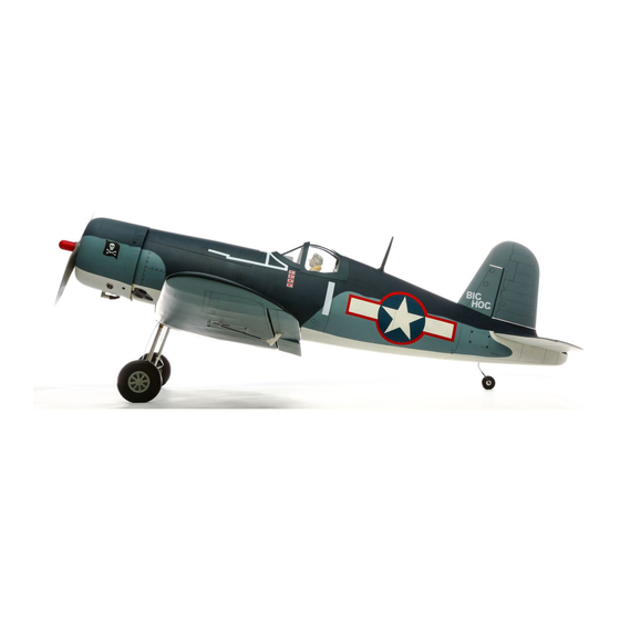
- Page 77 •DECAL INSTALLATION The decal sheet includes markings for three VF-17 ‘Jolly Rogers’ aircraft. Shown here is LCDR Tom Blackburn’s ‘BIG •ANBRINGEN DER DEKORBOGEN HOG’. Decal placement for alternate schemes are similar, so •POSE DES AUTOCOLLANTS online resources are a good reference for details on Lt. Doris •INSTALLAZIONE DEGLI ADESIVI Freeman’s ‘LA City Limits’...
-
Page 79: Center Of Gravity
•CENTER OF GRAVITY •DER SCHWERPUNKT An important part of preparing the aircraft for fl ight is properly balancing the model. Ein sehr wichtiger Teil in der Flugvorbereitung ist es das Flugzeug richtig auszubalancieren. 1. Attach the wing panels to the fuselage. Make sure to connect the leads from the aileron to the appropriate leads from the 1. -
Page 80: Centre De Gravité
•CENTRE DE GRAVITÉ •CENTRO DI GRAVITA’ (BARICENTRO) Une des étapes importantes de la préparation d’un modèle est son équilibrage. Un punto importante per preparare l’aereo al volo è quello di fare un centraggio corretto. 1. Fixez les ailes au fuselage. Vérifi ez que les ailerons sont reliés aux prises appropriées du récepteur. Contrôlez que les câbles 1. -
Page 81: Control Throws
•CONTROL THROWS •RUDERAUSSCHLÄGE 1. Turn on the transmitter and receiver of your model. Check the movement of the rudder using the transmitter. When the stick 1. Schalten Sie den Sender und Empfänger ihres Modells ein. Prüfen Sie die Seitenruderaussschläge mit dem Sender. is moved to the right, the rudder should also move right. -
Page 82: Débattements
•DÉBATTEMENTS •CORSE DEI COMANDI 1. Mettez l’émetteur et le récepteur sous tension. Contrôlez les mouvements de la dérive en utilisant votre émetteur. Quand le 1. Accendere trasmettitore e ricevitore del modello. Controllare i movimenti del timone agendo sul trasmettitore. Quando manche est vers la droite, la dérive doit s’orienter vers la droite. -
Page 83: Preflight Checklist
•PREFLIGHT CHECKLIST •VORFLUGKONTROLLE •CHECKLIST D’AVANT VOL •LISTA DEI CONTROLLI PRIMA DEL VOLO • Charge the transmitter, receiver and motor battery for • Laden Sie den Sender- ,Empfänger- und Zündakku für • Chargez la batterie de votre émetteur, de réception • Caricare le batterie di trasmettitore, ricevitore e your airplane. -
Page 84: Daily Flight Checks
•DAILY FLIGHT CHECKS •TÄGLICHER FLUG CHECK •CONTRÔLES SYSTÉMATIQUES •CONTROLLI DI VOLO GIORNALIERI • Check the battery voltage of the transmitter battery. Do • Überprüfen Sie die Spannung des Senderakkus. Fliegen • Contrôlez la tension de la batterie de l’émetteur. Ne volez •... - Page 85 An Online Service Request is available at accepts money orders and cashier’s checks, as well as Visa, service by anyone other than a Horizon Hobby authorized of use, setup or assembly, the user accepts all resulting http://www.horizonhobby.com/content/_service-center_ MasterCard, American Express, and Discover cards.
-
Page 86: Garantie Und Service Informationen
Reparaturversuche, die nicht von Horizon ausgeführt wurden aus. Rücksendungen durch den Käufer direkt an Horizon oder Anleitung enthält Sicherheitshinweise und Vorschriften Exklusive Garantie ¬ Horizon Hobby LLC (Horizon) Liegt eine kostenpfl ichtige Reparatur vor, erstellen wir einen eine seiner Landesvertretung bedürfen der Schriftform. -
Page 87: Garantie Et Réparations
Questions, assistance et réparations Réparations payantes ou d’une manipulation erronés, d’accidents ou encore du Garantie exclusive - Horizon Hobby, LLC (Horizon) garantit fonctionnement ainsi que des tentatives d’entretien ou de Votre revendeur spécialisé local et le point de vente ne En cas de réparation payante, nous établissons un devis... - Page 88 Horizon non si riterrà responsabile per danni speciali, Se il prodotto deve essere ispezionato o riparato, si prega di La garanzia esclusiva - Horizon Hobby, LLC, (Horizon) diretti, indiretti o consequenziali; perdita di profi tto o di rivolgersi ad un rivenditore specializzato o direttamente ad garantisce che i prodotti acquistati (il “Prodotto”) sono...
-
Page 89: Instructions For Disposal Of Weee By Users In The European Union
Horizon Hobby Limited +44 (0) 1279 641 097 Harlow, Essex, CM18 7NS, United Kingdom Horizon Technischer Service service@horizonhobby.de Christian-Junge-Straße 1 Germany Sales: Horizon Hobby GmbH +49 (0) 4121 2655 100 25337 Elmshorn, Germany infofrance@horizonhobby.com Service/Parts/Sales: 11 Rue Georges Charpak France... -
Page 90: Academy Of Model Aeronautics National Model Aircraft Safety Code
•ACADEMY OF MODEL AERONAUTICS NATIONAL MODEL AIRCRAFT SAFETY CODE Effective January 1, 2014 EXCEPTIONS: 3. At all fl ying sites a safety line(s) must be established in C. FREE FLIGHT front of which all fl ying takes place. (AMA Document #706.) A. - Page 91 • FLAP TEMPLATE •KLAPPENSCHALBONE •GABARIT DE RÉGLAGE DES VOLETS •SAGOMA PER I FLAP...
- Page 92 © 2014 Horizon Hobby, LLC. Hangar 9, DSMX, Evolution, UltraCote, EC5 and the Horizon Hobby logo are trademarks or registered trademarks of Horizon Hobby, LLC. The Spektrum trademark is used with permission of Bachmann Industries, Inc. All other trademarks, service marks and logos are the property of their respective owners.