
Manuels Connexes pour Horizon Hobby Hangar 9 PA-18-150 Super Cub


Sommaire des Matières pour Horizon Hobby Hangar 9 PA-18-150 Super Cub
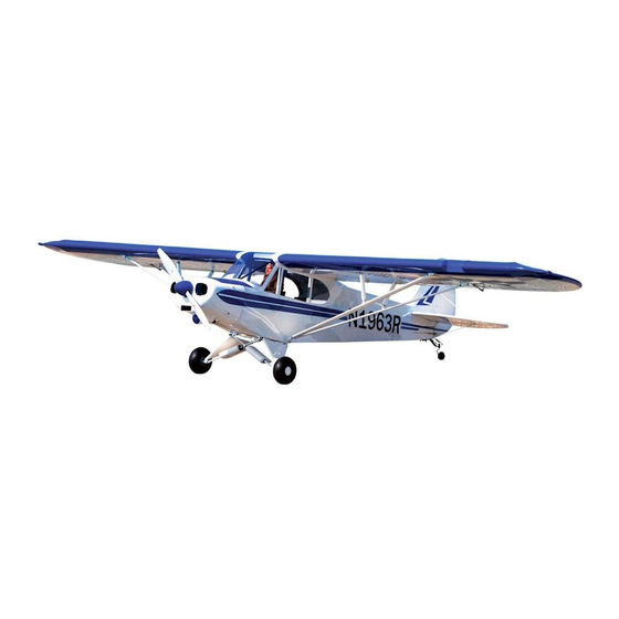
- Page 1 Instruction Manual 1/4 PA-18-150 Super Cub Bedienungsanleitung Manuel d’utilisation Manuale di Istruzioni...
-
Page 2: Using The Manual
Alle Anweisungen, Garantien und anderen zugehörigen Dokumente können im eigenen Ermessen von Horizon Horizon Hobby, Inc. For up-to-date product literature, visit horizonhobby. com and click on the support tab for Hobby, Inc. jederzeit geändert werden. Die aktuelle Produktliteratur finden Sie auf horizonhobby.com unter der this product. -
Page 3: Utilisation Du Manuel
Tutte le istruzioni, le garanzie e gli altri documenti pertinenti sono soggetti a cambiamenti a totale discrezione d’Horizon Hobby, Inc. Pour obtenir la documentation à jour, rendez-vous sur le site horizonhobby.com et cliquez di Horizon Hobby, Inc. Per una documentazione aggiornata sul prodotto, visitare il sito www.horizonhobby.com sur l’onglet de support de ce produit. -
Page 4: Safety Warnings And Precautions
è opportuno far riferimento appropriate Horizon Hobby office. Komponenten. Sollten Fragen zur Kompatibilität auftreten, à ce manuel ou contactez le service technique Horizon Hobby. alle istruzioni relative al prodotto o ai componenti oppure lesen Sie bitte die Produkt- oder Bedienungsanweisung oder rivolgersi al reparto Horizon Hobby di competenza. -
Page 5: Safe Operating Recommendations
safe operating reCoMMendations eMpfehlUngen ZUM siCheren Consignes de séCUrité ConCernant raCCoMandaZioni per operare in betrieb l’Utilisation siCUreZZa • Inspect your model before every flight to ensure it is airworthy. • Überprüfen Sie zur Flugtauglichkeit ihr Modell vor jedem • Inspectez votre modèle avant chaque vol. • Controllare attentamente il modello prima di ogni volo per Flug. - Page 6 speCifiCations/speZifikationen/ large parts layoUt/baUteile (ohne kleinteile)/ spéCifiCations/speCifiChe grandes pièCes/sCheMa dei CoMponenti grandi 106 in (269cm) 1630 sq in (150 dm ) Total/Totale 68.0 in (173 cm) 16.5–18.5 lb (7.5–8.4 kg) 2-Stroke Gas/2-Takt Benziner/ 2 temps Essence/2-Tempi Gas 20–26cc 4-Stroke Gas/4-Takt Benziner/ 4 temps Essence/4-Tempi Gas 30cc 2-Stroke Glow/2-Takt Glühzünder/...
- Page 7 replaCeMent parts/ersatZteile/pièCes de reChange/riCaMbi english deutsch français italiano HAN454001 Fuselage Rumpf Fuselage Fusoliera HAN454002 Left Wing with Aileron and Flap Tragfläche Links mit Querruder und Klappe Aile gauche avec aileron et volet Semiala sinistra con alettone e flap HAN454003 Right Wing with Aileron and Flap Tragfläche Rechts mit Querruder und Klappe Aile droite avec aileron et volet Semiala destra con alettone e flap...
- Page 8 asseMbly syMbol gUide/Montage syMbole /gUide des syMboles poUr asseMblage /gUida ai siMboli di asseMblaggio Apply threadlock Ensure free rotation Use medium CA Use a pencil Schraubensicherungslack verwenden Rotation sicherstellen Mittelflüssigen Verwenden Sie einen Bleistift Sekundenkleber verwenden Utilisez du frein filet Permettez une rotation libre Utilisez un crayon à...
- Page 9 reqUired radio eqUipMent/erforderliChe rC aUsrÜstUng/eqUipeMent radio reqUis/appareCChiatUre radio english deutsch français italiano SPMAR9020 AR9020 9-Channel DSMX X-Plus Receiver Spektrum AR9200 DSMX 9 Kanal X Plus Empfänger Récepteur AR9020 9-voies DSMX X-Plus AR9020 9-Canali DSMX X-Plus Ricevitore ® ™ JRPA004 Chargeswitch Ladestecker Interrupteur de charge JR JR Interruttore per carica...
- Page 10 eleCtriC power/elektroantrieb/MoteUr eleCtriqUe (ep)/Motore elettriCo english deutsch français italiano EFLM4110A Power 110 Outrunner Brushless, 295Kv Power 110 Außenläufer Brushless, 295Kv Power 110 Outrunner Brushless, 295Kv Power 110 Cassa rotante Brushless, 295Kv CSE010006700 Phoenix ICE 75 Brushless ESC Phoenix ICE 75 Brushless ESC / Regler CEV (ESC) Brushless Phoenix ICE 75 Phoenix ICE 75 Brushless ESC (regolatore) APC19010E...
- Page 11 reqUired adhesives/erforderliChe klebstoffe/types de Colles reqUis/adesivi neCessari english deutsch français italiano PAAPT56 Canopy Glue Kabinenhaubenkleber Colle à verrière Colla per il tettuccio PAAPT03 Medium CA Sekundenkleber mittel Colle cyano moyenne Medio CA PAAPT09 Thin CA Sekundenkleber dünnflüssig Colle cyano fine Sottile CA PAAPT42 Threadlock...
- Page 12 reqUired tools/benötigtes werkZeUg/oUtils reqUis/attreZZi neCessari english deutsch français italiano Adjustable wrench Adjustable wrench Clé ajustable Chiave regolabile Clear tape klares Klebeband Ruban adhésif transparent Nastro trasparente Covering iron Folienbügeleisen Fer à entoiler Ferro per ricopertura Crimping tool Crimpzange Pince à sertir Pinza crimpatrice Denatured alcohol Spiritus...
-
Page 13: Before Starting Assembly
Razor saw Säge Lame de rasoir Sega Razor Reamer Reibahle Alésoir Alesatore Ruler Lineal Réglet Righello Scissors Schere Ciseaux Forbici Side cutters Seitenschneider Pince coupante Lama laterale Wire Stripper Abisolierzange Pince à dénuder Spellafili before starting asseMbly vor deM ZUsaMMenbaU avant de CoMMenCer l’asseMblage priMa di iniZiare il Montaggio • Remove parts from bag. - Page 14 aileron and flap hinging/Montage der klappen Und qUerrUder/pose des Charnières de l’aileron et dU volet/Cerniere flap e alettoni ‰ ‰ ‰ ‰ Apply a small amount of oil to the flex point of the hinge to Slide the hinge into position. Position as shown, checking to The hinge must be positioned as shown.
- Page 15 ‰ ‰ ‰ ‰ Apply epoxy to the outside of the hinge using a toothpick. Position the hinges in the flap. Use care not to damage the Trim the opening for the flap hinges, removing any excess Fit the flap to the wing. Align the flap with the wing, then use Install the hinges and allow the epoxy to fully cure before scale covering on the flap.
- Page 16 ‰ ‰ ‰ ‰ Ensure the flap control horn aligns with the hole in the Position the aileron on the wing. Use low-tack tape to hold Once fit, use epoxy on both the wing and aileron to glue the trailing edge of the right and left wing for the flap linkage. the aileron in aligning at the wing tip.
- Page 17 aileron and flap linkages/anlenkUngen qUerrUder Und landeklappen/ ‰ ‰ tringleries de l’aileron et dU volet/CollegaMenti di alettoni e flap ‰ ‰ 4-40 Use epoxy to glue the hinges to the wing and flap. Use a Once the epoxy cures, apply thin CA to fully secure the paper towel and rubbing alcohol to remove excess epoxy hinges.
- Page 18 ‰ ‰ ‰ ‰ Thread a servo mounting screw into each of the holes in the Apply a small amount of thin CA to harden the threads made Mount the servo to the cover. The output of the servo is aileron servo mounting holes.
- Page 19 ‰ ‰ ‰ ‰ M2.5 x 8 Center the aileron servo using the radio system. Attach the Prepare both aileron servos at this time. Thread a screw into each of the holes in the aileron servo Apply a small amount of thin CA to harden the threads made servo arm so it is one spline from perpendicular.
- Page 20 ‰ ‰ ‰ ‰ 4-40 Tie the string located inside the wing to the end of the 24- Lift the cover for the flap servo. Use the string to pull the Assemble the aileron linkage using a 4-40 x 1 -inch inch (609 mm) extension.
- Page 21 ‰ ‰ ‰ ‰ Connect the linkage to the servo horn and aileron control Remove the flap cover. Mark the bottom of the cover so it can Center (mid-flap position) the flap servo using the radio Prepare both flap servos at this time. horn.
- Page 22 ‰ ‰ ‰ ‰ Connect the clevis to the flap control horn. Slide the silicone Use the string inside the wing to pull the flap and aileron With the servo output shaft facing towards the trailing edge With the radio on and the flap set to the UP position, place tubing over the forks of the clevis to secure its position.
- Page 23 ‰ ‰ ‰ ‰ M2.5 x 8 Adjust the length of the flap linkage so the flap is centered Secure the servo cover to the wing using four M2.8 x 8 self- Use hobby scissors and sandpaper to trim the slot in the Position the cover so it is 25 mm forward of the aileron hinge when the flap is in the UP position.
- Page 24 wing strUt installation/Montage der tragfläChenstreben/installation des haUbans d’aile/installaZione dei Montanti dell’ala ‰ ‰ ‰ ‰ 4-40 x 5/8 inch 4-40 4-40 x 5/8 inch Attach the strut bracket to the bottom the wing. Use a pin vise and 1/8-inch (3 mm) drill bit to remove any Thread the jury strut mounts into the holes in the wing.
- Page 25 ‰ ‰ ‰ 4-40 x 1/2 inch 4-40 4-40 x 5/8 inch 4-40 Attach the narrow strut to the rear bracket. The mount for the Attach the jury struts and the spreader bar to the front and jury strut must face the wing. rear struts.
- Page 26 landing gear installation/Montage des fahrwerk/installation dU train d’atterrissage/installaZione del Carrello di atterraggio ‰ ‰ ‰ ‰ Separate the inner and outer bungee struts. Clean the inner Apply a few drops of light machine oil to the inner strut. Make sure the inner strut slides easily in the outer strut. strut using 0000 steel wool and a paper towel.
- Page 27 ‰ ‰ Check that the screws are centered and have not moved during shipping. Wrap a rubber band around the screws Repeat the previous step to install the remaining three rubber bands. A total of 4 rubber bands will be installed on the strut Use a rotary tool and sanding drum to remove any rough between the inner and outer strut.
- Page 28 ‰ ‰ ‰ ‰ M3 x 15 4-40 x 5/8 inch 8-32 x 1/2 inch 4-40 Secure the bungee strut to the landing gear airfoil cover. Secure the main gear to the fuselage. The strut bracket fits Attach the cross brace to the front main gear mounts. between the fuselage and rear main gear mount.
- Page 29 ‰ ‰ ‰ ‰ M3 x 3 M4 x 4 M2.5 x 16 Secure the wheel collar to the axle. Tighten the setscrew on Remove the hubs from the wheel assembly. Slide the axle Slide the hubs into position, capturing the wheel collar Slide the axle into the main gear.
- Page 30 rUdder hinges/rUdersCharniere/Charnieres de direCtion/Cerniere tiMone ‰ ‰ ‰ ‰ Snap the hubcap into the wheel hub. A very small amount of silicone adhesive can be used if the hub fits loosely. Trim the opening for the rudder hinges, removing any excess Apply a small amount of oil to the flex point of the hinge to Fit the rudder hinges.
- Page 31 ‰ ‰ ‰ ‰ Install the three hinges. Check their operation and position Use a pin vise and 5/64-inch (2 mm) drill bit to drill the before the epoxy cures. holes for the control horn mounting screws. Position the hinge perpendicular to the hinge line. Check Bauen Sie die drei Scharniere ein, prüfen Sie Funktion und Bohren Sie mit einem 2 mm Handbohrer die Löcher für die that it can move freely.
- Page 32 a (lighting kit only/nUr Mit b (lighting kit only/nUr Mit C (lighting kit only/nUr Mit ‰ ‰ ‰ ‰ beleUChtUngskit/kit d’eClairage UniqUeMent/ beleUChtUngskit/kit d’eClairage UniqUeMent/ beleUChtUngskit/kit d’eClairage UniqUeMent/ kit di illUMinaZione) kit di illUMinaZione) kit di illUMinaZione) Check the fit of the rudder hinges to the fin. If the optional lighting is installed, route the wiring through the rudder.
- Page 33 d (lighting kit only/nUr Mit ‰ ‰ ‰ ‰ beleUChtUngskit/kit d’eClairage UniqUeMent/ kit di illUMinaZione) M2 x 10 Solder the lighting extension to the clear tail light. Stagger Once the fit of the hinges has been checked, use epoxy to Use a hobby knife to make a small hole in the bottom of the Secure the lens over the light.
- Page 34 rUdder servo installation/einbaU des seitenrUderservos/installation dU servo de direCtion/installaZione servo del tiMone ‰ ‰ ‰ ‰ Insert the end of the cable into the cable tubes for the Slide the cable though the tubes inside the fuselage. Pull the Slide a crimp on the cable, then the cable through the cable Loop the cable through the crimp a second time.
- Page 35 ‰ ‰ ‰ ‰ 4-40 Thread a servo mounting screw into each of the holes in Install the grommets and eyelets in the servo. Center the the rudder servo mounting holes. Remove the screws before servo using the radio system. Secure a large servo horn to proceeding.
- Page 36 ‰ ‰ ‰ ‰ 4-40 Mount the rudder servo using the hardware included with the Connect the rudder servo to the receiver. Use the radio Use low-tack tape to hold the rudder centered when servo. Connect the clevises from the cables to the horn in the system to hold the rudder servo centered.
- Page 37 tail wheel installation/Montage des spornrad/ ‰ installation de la roUlette de qUeUe/installaZione della rUota di Coda ‰ ‰ ‰ Remove the low-tack tape from the rudder. Check the Use a pin vise and 1/16-inch (1.5 mm) drill bit to drill the operation of the rudder using the radio system.
- Page 38 ‰ ‰ ‰ ‰ 4-40 x 1/2 inch M2 x 16 Carefully bend the ends of the tiller arm so they align with the tail wheel control arm. Secure the tiller arm to the bottom of the rudder. Attach the tail wheel bracket to the fuselage. The lower tail Pass the tail control spring cable through the tail spring Biegen Sie vorsichtig die Enden des Hebelarmes so dass strut bracket is installed at this time.
- Page 39 ‰ ‰ ‰ ‰ Install the crimp and secure the cable using the same Place the hook on the rudder control spring through the tiller Slide a crimp on the cable, then the cable through the rudder Pass the cable back through the crimp, pulling it to center technique as the rudder control cables.
- Page 40 wing installation/Montage der tragfläChen/installation de l’aile/Montaggio dell’ala ‰ ‰ ‰ Thread the nuts and aluminum strut end on the struts. The Move the aileron and flap leads from the holder in the wing and connect the leads to the extensions leading out of the position will be adjusted once the wing is on the fuselage.
- Page 41 stabiliZer installation/einbaU des höhenleitwerks/ ‰ ‰ installation dU stabilisateUr/installaZione dello stabiliZZatore ‰ ‰ Thread the nylon wing bolt into position, securing the wing to Adjust the position of the fittings so the hole in the fitting Slide the stabilizer into the slot in the fuselage. Center the the fuselage.
- Page 42 ‰ ‰ ‰ ‰ Measure from the tip of the stabilizer to the wing. Position the stabilizer so both measurements are equal. (Cowling has not been installed at this time.) Check all alignments. Mark the outline of the fuselage on the Use a ruler and carefully cut the covering 1/8 inch (3 mm) top and bottom of the stabilizer.
- Page 43 stabiliZer sUpport installation/Montage der leitwerksstreben/ ‰ installation des haUbans dU stabilisateUr/installaZione sUpporti stabiliZZatore ‰ ‰ ‰ 250 mm Make sure to use enough epoxy to securely glue the stabilizer to the fuselage. Use a paper towel and rubbing alcohol to 4-40 x 3/8 inch 4-40 remove excess epoxy from the fuselage and stabilizer.
- Page 44 ‰ ‰ ‰ ‰ 4-40 x 5/8 inch 4-40 Stand back from the model 8 to 10 feet (2 to 3 meters) and view the model from the front. The stabilizer must align with the wing. Adjust as necessary. (Cowling has not been The holes in the ends of the upper and lower rods must align Prepare the stabilizer leading edge cover.
- Page 45 elevator installation/Montage des höhenrUders/installation de la profondeUr/installaZione dell’elevatore ‰ ‰ ‰ ‰ Drill the holes for the control horn mounting screws using a pin vise and 5/64-inch (2 mm) drill bit. Inspect the elevators to determine which side is up. The Install the hinges.
- Page 46 ‰ ‰ ‰ M2 x 16 Prepare both the left and right control horns. Test fit, then secure, the hinges in the stabilizer. Remove excess epoxy using a paper towel and rubbing alcohol. Use Bereiten Sie beide Ruderhörner vor. low-tack tape to hold the elevator in position until the epoxy cures.
- Page 47 elevator servo installation/einbaU des höhenrUderservos/installation dU servo de profondeUr/installaZione del servo elevatore ‰ ‰ ‰ ‰ 4-40 4-40 x 5/8 inch 4-40 Prepare the holes for the servo mounting screws following Secure the ball link to the servo horn using the hardware Slide the pushrod into the tube, exiting the rear of the Thread a 4-40 nut on the pushrod.
- Page 48 ep Motor installation/ e-Motor einbaU/installation dU MoteUr ep/installaZione del Motore elettriCo ‰ ‰ ‰ ‰ 8-32 8-32 x 1 inch Place the engine mounting template in position on the Remove the template from the firewall. Use a drill and 7/32- firewall.
- Page 49 ‰ ‰ ‰ ‰ Use a rotary tool and sanding drum to remove material from Prepare the speed control by soldering the appropriate the firewall to allow the wires from the speed control to pass connector to the speed control leads. Secure the speed into the fuselage.
- Page 50 gas engine installation/benZin Motor einbaU/ installation dU MoteUr a essenCe/installaZione di Un Motore a sCoppio ‰ ‰ ‰ ‰ Place the engine mounting template in position on the Remove the template from the firewall. Use a drill and 7/32- Cut the throttle pushrod tube to a length of 170 mm. Sand firewall.
- Page 51 ‰ ‰ ‰ ‰ Secure the fuel tube to the fitting on the stopper by twisting Insert the stopper in the tank. Make sure the clunk can Insert the assembled tank inside the fuselage, guiding the Use a rubber band to secure the tank mounting plate in the wire using pliers.
- Page 52 ‰ ‰ ‰ ‰ 8-32 8-32 x 1 inch Mount the kill switch to the side of the fuselage. Make sure the wires pass through the hole in the firewall so they can be connected to the engine. Use a hobby knife with a #11 blade to remove the covering Use a drill, 3/16-inch (4.5 mm) drill bit and hobby knife to Secure the engine to the firewall using the hardware and from the side of the fuselage to mount the engine kill switch.
- Page 53 ‰ ‰ ‰ ‰ 2-56 2-56 x 1/2 inch If you are using an engine not listed in this manual, make Prepare the holes for the servo following the procedure sure that when installed, the distance from the firewall to outlined earlier in this manual.
- Page 54 ‰ ‰ ‰ ‰ M3 x 12 M3 x 12 Connect the fuel lines to the carburetor. Use a fuel dot to Route the vent line to the bottom of the fuselage. Secure the Secure the muffler to the engine. allow access from outside the cowl to fill and drain the tubing to the firewall using a nylon bracket and screw (you Schrauben Sie den Schalldämpfer an den Motor.
- Page 55 26 (saito 1.82) ‰ ‰ M3 x 3 Operate the throttle to make sure the carburetor moves from the fully-open to the fully-closed positions without binding. If not, adjust the end points at the transmitter so the servo operates the carburetor without binding. Once the throttle is operating correctly, tighten the setscrew to secure the pushrod wire.
- Page 56 Cowling installation/einbaU MotorhaUbe/installation dU Capot/installaZione Capottina Motore 1 (gas only/nUr benZinMoto/essenCe 2 (gas only/nUr benZinMoto/essenCe 4 (ep only/nUr e-Moto/ep UniqUeMent/ ‰ ‰ ‰ ‰ UniqUeMent/solo Motore a sCoppio) UniqUeMent/solo Motore a sCoppio) solo Motore elettriCo) Slide the cowl into position, centering the back plate for the Trim a small notch to allow clearance for the propeller shaft Trim the cowl to fit over the engine.
- Page 57 ‰ ‰ ‰ ‰ M3 x 12 Slide the spinner back plate on the motor shaft. Temporarily Use a drill and 1/16-inch (1.5 mm) drill bit to drill the holes attach the propeller to hold the back plate in position. Set for the cowl mounting screws.
- Page 58 11 (gas only/nUr benZinMoto/essenCe ‰ ‰ ‰ ‰ UniqUeMent/solo Motore a sCoppio) M3 x 12 Install the spinner back plate and propeller. Secure the Secure the spinner cone to the motor. Make sure the blades propeller using the nut and washer included with the motor/ Secure the spinner adapter using a 1/2-inch wrench.
- Page 59 reCeiver and reCeiver battery installation/einbaU von eMpfänger Und eMpfängerakkU/ installation dU réCepteUr et de la batterie dU réCepteUr/installaZione di riCevitore e batteria ‰ ‰ ‰ Wrap the receiver battery in 1/4-inch (4 mm) foam to protect Mount the switch harness in the fuselage using the Connect the leads for the servos to the receiver.
- Page 60 7a (CoCkpit kit/CoCkpit kit/kit de CoCkpit/kit abitaColo) ‰ ‰ ‰ Secure the receiver using a hook and loop strap. Make sure to place foam between the receiver and fuselage to protect the receiver from vibration. Sichern Sie den Empfänger mit einer Klettschlaufe. Bitte achten Sie darauf zur Dämpfung unter den Empfänger Schaumstoff zu legen.
- Page 61 7b (no CoCkpit kit/ohne CoCkpit kit/ sans le kit de CoCkpit/senZa kit abitaColo) optional lighting installation/einbaU der optionalen beleUChtUng/ ‰ installation d’éClairage en option/installaZione delle lUCi opZionali ‰ ‰ Connect the 18-inch (457 mm) lead from the receiver to the lighting controller.
- Page 62 ‰ ‰ ‰ ‰ Connect a 36-inch (914mm) and 18-inch (457 mm) lighting Tie the string around the end of the leads. Make sure the Wrap a piece of tape around the string as shown. This will lead. Secure the leads using string or heat shrink so they do connector will plug into the lead exiting the fuselage.
- Page 63 ‰ ‰ ‰ ‰ Use medium CA to glue the green (left) light in the light Remove the covering so the lighting plate and leads for the Tie the string around the end of the 18-inch (457 mm) Wrap a piece of tape around the string as shown. This will housing.
- Page 64 ‰ ‰ ‰ ‰ 18 inches 36 inches (457mm) (914mm) 6 inches (152mm) Prepare the lighting harness using a 36-inch (914 mm) Connect the landing lights to the lighting harness. Make lighting extension, the 18-inch (457 mm) lighting extension sure the landing light plate can be attached without that is connected to the light at the wing tip and two 6-inch interference from the wiring harness.
- Page 65 CoCkpit-interior/CoCkpit-innenaUsbaU/CoCkpit-intérieUr/abitaColo-interno ‰ ‰ ‰ ‰ 4-40 Carefully drill the door handle knob using a 1/8-inch (3 mm) Secure the lighting plate to the wing. Use canopy glue to secure the landing light lens to the wing. drill bit. Slide the knob on the handle. It will fit tightly, so use The shape of the lens will match the airfoil, so make sure to care when installing it on the handle.
- Page 66 ‰ ‰ ‰ ‰ 4-40 There are two different control sticks provided. The control stick with the longer threaded portion threads into the front position, while the shorter is used in the rear position. Place a washer on the threaded portion of the door handle, Secure the door handle using a lock nut and washer.
- Page 67 9 (ep only/nUr e-Moto/éleCtriqUe 10a (gas or glow/benZin oder 10b (ep only/nUr e-Moto/éleCtriqUe ‰ ‰ ‰ ‰ (ep) UniqUeMent/solo Con Motore glÜhZÜnder/essenCe oU (ep) UniqUeMent/solo Con Motore elettriCo) inCandesCenCe/Motori a sCoppio) elettriCo) Secure the batteries to the battery tray using hook and loop Place the cover into position and thread the control stick in Place the front cover into position in the fuselage.
- Page 68 ‰ ‰ Place the seats into the fuselage. They are held in position Remove the life vest and helmet from the pilot. Use silicone using magnets. adhesive to glue the boots to the pilots feet so they stay attached to the pilot when he is removed. Place the pilot in Setzen Sie die Sitze in den Rumpf ein.
- Page 69 optional interior installation/ optionaler innenaUsbaU/ installation d’intérieUr en option/installaZioni interne opZionali ‰ ‰ The installation of the cockpit kit will require the modeler ‰ to test-fit the various sections BEFORE they are glued into position. Laser-cut lines have been located inside the fuselage for the items detailed in this section of the manual.
- Page 70 ‰ Use the previous photos as a reference when installing the interior in your model. Nutzen Sie die Fotos als Referenz bei dem Einbau des Interieurs. Se référer aux photos des pages précédentes lors de l’installation de l’intérieur dans votre modèle. Quando si installano gli interni di questo modello, usare questa sequenza di foto come riferimento.
- Page 71 window installation/Montage der fenster/installation des vitrages/installaZione delle finestre ‰ ‰ ‰ ‰ Lightly sand the front windscreen and side windows where Lightly sand the fuselage where the windows and windscreen Use canopy glue to glue the front windscreen to the fuselage. they contact the fuselage.
- Page 72 ‰ Use canopy glue to glue the remaining windows to the fuselage. Use low-tack tape to hold the windows in position until the glue cures. Kleben Sie die weiteren Fenster mit Kabinenhaubenkleber an den Rumpf. Fixieren Sie die Fenster mit Klebeband mit geringer Klebekraft.
-
Page 73: Center Of Gravity
Center of gravity der sChwerpUnkt Centre de gravité Centro di gravita’ (bariCentro) An important part of preparing the aircraft for flight is Ein sehr wichtiger Teil in der Flugvorbereitung ist es das Une des étapes importantes de la préparation d’un modèle Un punto importante per preparare l’aereo al volo è... -
Page 74: Control Throws
Control throws rUderaUssChläge 1. Turn on the transmitter and receiver of your model. Check the movement of the rudder using the transmitter. When the stick 1. Schalten Sie den Sender und Empfänger ihres Modells ein. Prüfen Sie die Seitenruderaussschläge mit dem Sender. is moved to the right, the rudder should also move right. -
Page 75: Corse Dei Comandi
débatteMents Corse dei CoMandi 1. Mettez l’émetteur et le récepteur sous tension. Contrôlez les mouvements de la dérive en utilisant votre émetteur. Quand le 1. Accendere trasmettitore e ricevitore del modello. Controllare i movimenti del timone agendo sul trasmettitore. Quando manche est vers la droite, la dérive doit s’orienter vers la droite. -
Page 76: Preflight Checklist
preflight CheCklist vorflUgkontrolle CheCklist d’avant vol lista dei Controlli priMa del volo • C harge the transmitter, receiver and motor battery for • L aden Sie den Sender- ,Empfänger- und Zündakku für • C hargez la batterie de votre émetteur, de réception • C aricare le batterie di trasmettitore, ricevitore e your airplane. Use the recommended charger supplied Ihr Flugzeug. Verwenden Sie für die RC Anlage bitte et d’allumage. -
Page 77: Daily Flight Checks
daily flight CheCks tägliCher flUg CheCk Contrôles systéMatiqUes Controlli di volo giornalieri • C heck the battery voltage of the transmitter battery. Do • Ü berprüfen Sie die Spannung des Senderakkus. Fliegen • C ontrôlez la tension de la batterie de l’émetteur. Ne volez • C ontrollare la tensione della batteria del trasmettitore. not fly below the manufacturer’s recommended voltage. Sie nicht wenn die Spannung unterhalb der vom jamais en dessous de la tension minimale recommandée Non volare se la tensione è... -
Page 78: Limitation Of Liability
By the act at our facility. An Online Service Request is available MasterCard, American Express, and Discover cards. By service by anyone other than a Horizon Hobby authorized of use, setup or assembly, the user accepts all resulting athttp://www.horizonhobby.com/content/_ service-center_... -
Page 79: Sicherheitshinweise
Sollten wir nach 90 Tagen keineEinverständniserklärung zur aus. Rücksendungen durch den Käufer direkt an Horizon oder Exklusive Garantie ¬ Horizon Hobby Inc (Horizon) Muss Ihr Produkt gewartet oder repariert werden, wenden Sie Reparatur vorliegen haben, behalten wir uns vor, das Produkt eine seiner Landesvertretung bedürfen der Schriftform. -
Page 80: Garantie Et Réparations
électroniques et les moteurs. les Garantie exclusive - Horizon Hobby, Inc. (Horizon) garantit Votre revendeur spécialisé local et le point de vente ne fonctionnement ainsi que des tentatives d’entretien ou de réparations touchant à... - Page 81 Manutenzione e riparazione Garanzia esclusiva - Horizon Hobby, Inc., (Horizon) Horizon non si riterrà responsabile per danni speciali, Se il prodotto deve essere ispezionato o riparato, si prega di garantisce che i prodotti acquistati (il “Prodotto”) sono diretti, indiretti o consequenziali;...
- Page 82 25337 Elmshorn, Germany service@horizonhobby.de Room 506, No. 97 Changshou Rd. +86 (021) 5180 9868 11 rue Georges Charpak +33(0)1 60 18 34 90 China Horizon Hobby – China France Horizon Hobby SAS Shanghai, China 200060 info@horizonhobby.com.cn 77127 Lieusaint infofrance@horizonhobby.com Room 506, No. 97 Changshou Rd.
-
Page 83: Ama National Model Aircraft Safety Code
aMa national Model airCraft safety Code effective January 1, 2011 b. radio Control (rC) (h) Not operate model aircraft while under the influence of 7. Under no circumstances may a pilot or other person touch alcohol or while using any drug which could adversely affect a model aircraft in flight while it is still under power, except a. - Page 84 © 2012 Horizon Hobby, Inc. Hangar 9, E-flite, Evolution, JR, DSMX, X-Plus, EC5 and Celectra are trademarks or registered trademarks of Horizon Hobby, Inc. Zenoah is a registered trademark of Husqvarna Zenoah Co. Ltd. Corporation and is used with permission.