Table des Matières
Publicité
Les langues disponibles
Les langues disponibles
Liens rapides
Installation and operating manual
RoCon UFH
Installation and operating manual
English
UFH-BM
UFH-UM
Installations- und Betriebsanleitung
Deutsch
UFH-RMD2
UFH-RMD6
Français
UFH-RD
Manuel d'installation et de fonctionnement
UFH-RMF2A
UFH-RMF6A
Montagehandleiding en gebruiksaanwijzing
Nederlands
UFH-RFT
Manuale d'installazione e d'uso
Italiano
12/2020
Publicité
Table des Matières

Manuels Connexes pour Daikin RoCon UFH


Sommaire des Matières pour Daikin RoCon UFH
- Page 1 Installation and operating manual RoCon UFH Installation and operating manual English UFH-BM UFH-UM Installations- und Betriebsanleitung Deutsch UFH-RMD2 UFH-RMD6 Français UFH-RD Manuel d'installation et de fonctionnement UFH-RMF2A UFH-RMF6A Montagehandleiding en gebruiksaanwijzing Nederlands UFH-RFT Manuale d'installazione e d'uso Italiano 12/2020...
- Page 3 Installation and operating manual RoCon UFH Installation and operating manual English UFH-BM UFH-UM UFH-RMD2 UFH-RMD6 UFH-RD UFH-RMF2A UFH-RMF6A UFH-RFT 12/2020...
- Page 4 About these operating instructions About these operating instructions These operating instructions describe the system "„RoCon UFH" for single room tem- perature control (also referred to as "product" in these operating instructions). These operating instructions are part of the product. •...
- Page 5 Comply with all safety instructions in conjunc- tion with this symbol to help avoid possible death, injury or equip- ment damage. This symbol alerts to hazardous electrical voltage. If this symbol is used in a safety message, there is a hazard of electric shock. RoCon UFH...
-
Page 6: Information On Safety
- If the product is operated in hazardous areas, sparks may cause deflagrations, fires or explosions • In conjunction with products which are used for health-saving or life-saving pur- poses or whose operation may incur hazards to humans, animals or property RoCon UFH... -
Page 7: Qualification Of Personnel
Modifications to the product Only perform work on and with the product which is explicitly described in these oper- ating instructions. Do not make any modifications to the product which are not described in these operating instructions. RoCon UFH... -
Page 8: Transport And Storage
Use the original packaging when transporting the product. • Store the product in a clean and dry environment. • Verify that the product is protected against shocks and impact during trans- port and storage. Failure to follow these instructions can result in equipment damage. RoCon UFH... - Page 9 Th base module supplies the room controllers with 5 V DC and the thermostatic actu- ators with 230 V AC. The single room temperature controller RoCon UFH can be switched between heating and cooling via the base module. The control circuit pumps can be controlled via the base module.
-
Page 10: Product Description
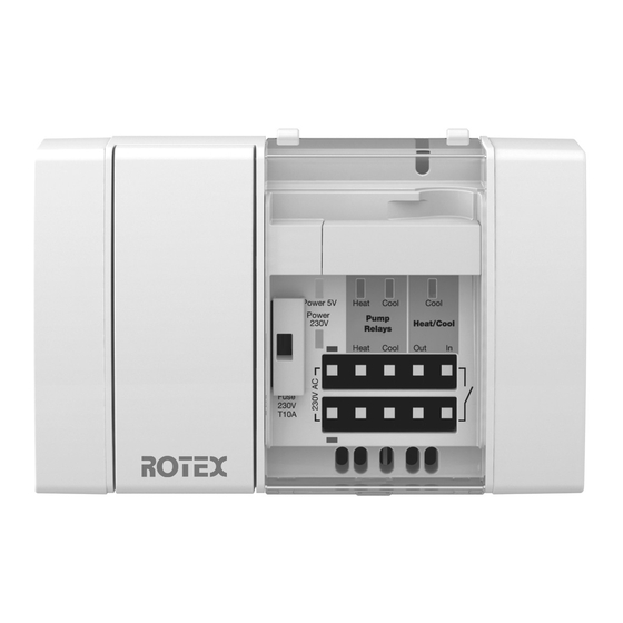
Product description Overview of the individual RoCon UFH components Component Versions Explanation Ordering number Base module RoCon UFH- 175137 Timer module RoCon UFH- 175138 Room tempera- RoCon UFH-RD Wired 175139 ture controller RoCon UFH- Wireless, temperature 175142 Controller mod- RoCon UFH-... - Page 11 Product description Overview Base module RoCon UFH-BM A. Fuse compartment B. Operation mains voltage (LED green) C. Operation 5 V (LED green) D. Pump Heating (LED red) E. Pump Cooling (LED blue) F. Cooling (LED blue) G. Input switchover Heating/ Cooling H.
- Page 12 Product description Controller modules wired A. Controller module RoCon UFH- 1. Catch RMD2 2. Operation mains voltage (LED green) B. Controller module RoCon UFH- 3. Thermostatic actuator active (LED RMD6 yellow) C. End cover 4. Terminal block for room controller RoCon UFH-RD 5.
- Page 13 Product description Controller modules wireless A. Controller module RoCon UFH 1. Teach-in key (LRN key) RMF2A 2. Catch B. Controller module RoCon UFH 3. Operation mains voltage (LED green) RMF6A 4. Thermostatic actuator active (LED C. End cover yellow) 5. Wireless module 6.
- Page 14 1. Rotary knob for adjusting the refer- ence temperature B. Room controller wireless UFH-RFT 2. LED red: Hearing LED blue: Cooling 3. Solar cell Fig. 4-4: Front view room controller The wireless system is only available in certain sales areas. RoCon UFH...
-
Page 15: Application Examples
Fig. 4-5: Single room temperature controller-RoCon UFH with one controller module RoCon UFH-RMD6 wired and 6 room controllers RoCon UFH-RD Fig. 4-6: Single room temperature controller RoCon UFH with one controller module RoCon UFH-RMF6A wireless and 6 room controllers RoCon UFH-RFT (1) The wireless system is only available in certain sales areas. -
Page 16: Technical Data
Product description Technical data Parameter Base module RoCon UFH-BM General specifications Dimensions housing 122 mm x 92 mm x 45 mm (W x H x D) Weight 215 g Housing material PC/ABS Colour Light grey, similar to RAL 7047 Operating temperature range Ambient -20 °C ... - Page 17 The following components may be connected to one controller module Room controllers Max. 2 Max. 6 Thermostatic actuators Per control circuit up to 4 Daikin UFH-Sat8 Electrical safety Protection class (EN 60730-1) Degree of protection IP 20 (EN 60529)
- Page 18 The following components may be connected to one controller module Room controllers Max. 2 Max. 6 Thermostatic actuators Per control circuit up to 4 Daikin UFH-Sat8 Electrical safety Protection class (EN 60730-1) Degree of protection IP 20 (EN 60529)
- Page 19 Product description Parameter Room controller wired Room controller wire- RoCon UFH-RD less RoCon UFH-RFT General specifications Dimensions (W x H x D) 78 mm x 78 mm x 78 mm x 82.5 mm x 12.5 mm 12.5 mm Weight 30 g...
- Page 20 Product description Parameter Room controller wired Room controller wire- RoCon UFH-RD less RoCon UFH-RFT Electromagnetic compatibility (EMC) Emitted interference/immu- EN 61326-1:2013 nity ® EnOcean wireless Radio Equipment Directive Frequency 868.3 MHz (RED) 2014/53/EU Transmission power max. 10 mW Additional information: www.enocean.com...
- Page 21 Product description Parameter Timer module RoCon UFH-UM General specifications Dimensions (W x H x D) 37 mm x 93 mm x 28 mm Weight 33 g Housing material Temperature reduction Functions Timing Date, time, weekday (leap year detection, switching between...
- Page 22 Product description Daikin recommends the use of Daikin UFH-Sat8 actuators to ensure optimum system performance. If actuators from other manufacturers are used, the following limit val- ues must be met: Operating voltage AC 230 V ±10 %, 50/60 Hz Max. operating current 9 mA Max.
-
Page 23: Dimensions
Product description Dimensions Individual dimensions Fig. 4-7: Dimensions of the individual components Dimensions mounted Fig. 4-8: Total lengths of versions D2/F2A (2 control circuits), D6/F6A (6 control circuits) and D6/F6A+D2/F2A (8 control circuits) RoCon UFH... - Page 24 Product description Information on RoCon UFH as per EN 60730-1:2016 • RoCon UFH is an electronic control type C as per EN 60730-1. • RoCon UFH is suitable for continuous operation. • The type of disconnection of the actuators and pumps is micro disconnection.
- Page 25 The product must be mounted in the vicinity of the heating circuit manifold. Mounting of the product Verify that the product is disconnected from mains 1. Open the cover using a screwdriver. Fig. 5-1: Opening the cover 2. Pull off the end cover. Fig. 5-2: Removing the end cover RoCon UFH...
- Page 26 Fig. 5-3: Connecting the base module to the controller module(s) 4. Refit the end cover onto the last controller module. Fig. 5-4: Refitting the end cover 5. Make the electrical connec- tions (see chapter 5.3) RoCon UFH...
- Page 27 Mounting 6. Refit the cover and close it. Fig. 5-5: Closing the cover RoCon UFH...
-
Page 28: Electrical Connection
- Verify that the correct assignment of the switch- ing channels for the timer module has been consid- ered. Verify that all cables are dis- connected from power. 1. Strip the cables as shown. Fig. 5-6: Stripping the cables RoCon UFH... -
Page 29: Connection Diagram
AC 250 V, 3 A max. DC 30 V, 3 A D. Options E. Pump cooling max. AC 250 V, 3 A F. Pump heating max. AC 250 V, 3 A Fig. 5-7: Connection diagram base module RoCon UFH... - Page 30 Heat Cool Heat Cool A. Upper floor D. Heating B. Ground floor E. Pump cooling max. AC 250 V, 3 A C. Basement F. Pump heating max. AC 250 V, 3 A Fig. 5-8: Connection diagram for cascading example RoCon UFH...
- Page 31 200 Lux, install a lithium battery 3V type 1632 in the battery compartment: 1. Remove the rotary knob and the upper part of the housing (see fig. 5-11) 2. Insert the battery into the battery compartment. Verify correct polarity. The wireless system is only available in certain sales areas. RoCon UFH...
- Page 32 Mounting Mounting position Cold walls and draughts affect temperature measurement. 1. Mount the product to an ≥ 30 cm indoor wall and at an ade- quate distance from doors and windows. Fig. 5-10: Positioning of room controller RoCon UFH...
- Page 33 C: Mounting directly to the wall. If the wall is uneven, stick the product to the wall using the adhesive dots sup- plied. Screw or glue the product to even walls. Fig. 5-12: Wall mounting of room controller RoCon UFH...
- Page 34 (B) at the rear of the product. 10. Fix the cable of the room temperature controller and the cable of the thermostatic actuator with the cable clamp (A). 11. Repeat this procedure for all other cables. Fig. 5-15: Routing cables RoCon UFH...
- Page 35 Fig. 5-16: Fitting the cable clamp 2. Repeat this procedure for all other cables. 3. It is possible to open the cable clamps. To do so, pull the two tabs (B) outwards and remove the cable clamp. Fig. 5-17: Releasing the cable clamp RoCon UFH...
- Page 36 1. Slightly lift the modules (base module and controller modules) and tilt the top away from the DIN rail. 2. Remove the modules (base module and controller modules) towards the bottom. Fig. 5-19: Removing module from DIN rail RoCon UFH...
- Page 37 Failure to follow these instructions can result in equipment damage. 1. Remove the cover from the base module. 2. Plug the product into the slot of the base module. Fig. 5-20: Inserting the timer module RoCon UFH...
- Page 38 1. Open the cover of the product. 2. Push the antenna cable onto the wire- less module and screw it on. 3. Close the cover of the product. See chapter 6.3.4 for information on mounting the adhesive antenna. Fig. 5-22: Mounting the antenna cable RoCon UFH...
-
Page 39: Preparation
This helps to avoid subsequent con- fusion. Verify that a paper clip bent open and a ballpoint pen are available. The wireless system is only available in certain sales areas. RoCon UFH... -
Page 40: Establishing A Connection
3. Press the LRN key of the product until the LED for the next control circuit flashes (for at least 0.5 seconds). - The next control circuit is in teach-in mode. Fig. 6-1: Establishing a connection to the controller module (1) RoCon UFH... - Page 41 (for at least two seconds) until the yellow LED for control circuit 1 starts flashing. - All taught-in room controllers of this product have been cleared. - The product is again in teach-in mode. Fig. 6-3: Deleting a controller module RoCon UFH...
- Page 42 6. Close the cover of the cabinet. If the reception is not sufficient with the adhesive antenna in the cabinet, the adhe- sive antenna must be mounted outside of the cabinet. 1. Open/remove the cover of the cabi- net. RoCon UFH...
- Page 43 2. Set the room controller to +30 °C. - After one minute, the yellow LED lights up at the controller module to which the room controller is connected. 3. Repeat this procedure for all other room controllers. RoCon UFH...
- Page 44 Goes off If no room temperature controller is requesting cooling. Cooling Solid lit If the controller is set to "Cooling". (LED blue) Goes off If the controller is set to "Heating". Table 7-1: LED signals in the base module RoCon UFH...
- Page 45 If the fuse in the base module trips. If the fuse (1) trips. LED yellow Solid lit When the room controller connected to this con- trol circuit is requesting heating energy or cool- ing. Table 7-2: LED signals in controller modules RoCon UFH...
- Page 46 Operation Fig. 7-3: LED position room controller wired Indication State Explanation Solid lit red During heating Solid lit blue During cooling Not lit Reference temperature reached Table 7-3: LED signals in the room controller wireless RoCon UFH...
- Page 47 +30 °C by means of restrictors. The restrictors can be adjusted to set the minimum and the maximum adjustable temperature. 1. Turn the cam screw at the product by approximately 90° using a screwdriver. 2. The rotary knob is lifted and can be removed. 90° Fig. 7-5: Removing the rotary knob RoCon UFH...
- Page 48 3. Turn the cam screw at the product back to the initial position so that you can refit the rotary knob. 4. Fit the rotary knob to the upper part of the housing. Fig. 7-7: Limiting the maximum temperature: RoCon UFH...
-
Page 49: Frost Protection Function
Operation 7.3.3 Frost protection function - RoCon UFH controls the room temperature to +8 °C - If the product is set to "Frost protection", the cool- ing function is disabled Fig. 7-8: Frost protection (+8 °C) Timer module For normal operation, the timer module must be inserted into the base module. For programming, it can be removed from the base module. - Page 50 - Confirm the settings. Menu key: 4. Briefly press the Menu key: - Navigate in the main menu. - Increase the adjustment values. 5. Hold down the Menu key for 3 sec- onds: - Activate fast forward. Fig. 7-9: Controls RoCon UFH...
-
Page 51: Display Elements
F. Switching output Additional Pump Running Time active G. Switching channel "Timer2" active H. Switching channel "Timer1" active I. Timer mode active J. Night mode active K. Day mode active L. Date (format DD.MM.YY) Fig. 7-10: Display elements RoCon UFH... -
Page 52: Main Screen
• Status of switching channels "Interval function" and "Additional pump running time" Fig. 7-11: Example of main screen: 12:00 p.m. March 26, 2012, Monday, operating mode Timer, switching channel Timer1 active, Additional Pump Running Time active and Interval function active RoCon UFH... -
Page 53: Setting The Operating Mode
5. Keep pressing the Menu key until the required minute is displayed. 6. Press the Set key to save the value. 7. The Seconds counter is reset to "0". 8. Set the date and the weekday in the same way as described above. RoCon UFH... - Page 54 Per switching output ("Timer1" and "Timer2"), 9 memory blocks are available. The switching outputs "Timer1" and "Timer2" can store the following data: • Start time • End time • Start weekday • End weekday • Switching channel "Timer1" active/inactive • Switching channel "Timer2" active/inactive RoCon UFH...
- Page 55 H. Switching channel "Timer1" active I. Timer mode active Fig. 7-14: Programming switching times To disable a memory block, the switching channels "Timer1" and "Timer2" must be inactive. The symbol "Timer" (I) flashes when both switching channels are inac- tive. RoCon UFH...
- Page 56 A. Switching channel "Timer1" Fig. 7-16: Assignment of the switching channels with the wireless controller module In the case of controller modules (wireless), switching channel "Timer1" controls all control circuits. The wireless system is only available in certain sales areas. RoCon UFH...
- Page 57 8. Press the Set key to save the interval. - The "Weekday" digits flash. 9. Keep pressing the Menu key until the required weekday (1 = Monday to 7 = Sunday) is displayed. 10.Press the Set key to save. RoCon UFH...
- Page 58 "Pu" is displayed. 2. Hold down the Set key for 3 seconds. - The digits for the switch on duration blink. 3. Press the Menu key to adjust the required value. 4. Press the Set key to save. RoCon UFH...
- Page 59 Fig. 7-19: Setting daylight saving time/winter time switching 1. Hold down the Set key for 3 seconds. 2. Press the Menu key. - The indicator flashes and toggles between "Auto" and "Off". 3. Press the Set key to save. RoCon UFH...
-
Page 60: Restoring The Factory Settings
End weekday Switching channel "Timer1" Inactive Switching channel "Timer2" Inactive Interval function Time 1.00 (1:00 a.m.) Duration of interval 5 minutes Weekday 3 (Wednesday) Additional pump running time Switch-on duration 0 minutes Table 7-4: Factory settings timer module RoCon UFH... - Page 61 Maintenance Maintenance Replace the optional battery of wireless room controllers, if necessary. All other sys- tem elements are maintenance-free. The wireless system is only available in certain sales areas. RoCon UFH...
-
Page 62: Replacing The Fuse
LED 5 V operation not lit No mains voltage Check the power supply (green LED) Fuse defective Check the fuse Power supply unit defective Contact the Daikin service hotline Other malfunctions Contact the Daikin service hotline Replacing the fuse Verify that the mains voltage is interrupted and cannot be switched on. - Page 63 Get in touch with us before returning your product. Spare parts and accessories NOTICE UNSUITABLE PARTS • Only use genuine spare parts and accessories provided by the manufac- turer. Failure to follow these instructions can result in equipment damage. RoCon UFH...
- Page 65 Installations- und Betriebsanleitung RoCon UFH UFH-BM UFH-UM Installations- und Betriebsanleitung Deutsch UFH-RMD2 UFH-RMD6 UFH-RD UFH-RMF2A UFH-RMF6A UFH-RFT 12/2020...
- Page 66 Über diese Betriebsanleitung Über diese Betriebsanleitung Diese Betriebsanleitung beschreibt das System „RoCon UFH“ (im folgenden auch „Produkt“) zur Einzelraum-Temperatur-Regelung. Diese Betriebsanleitung ist Teil des Produkts. • Sie dürfen das Produkt erst benutzen, wenn Sie die Betriebsanleitung vollständig gelesen und verstanden haben.
- Page 67 Verletzungen und Sachschäden hin. Befolgen Sie alle im Zusam- menhang mit diesem Warnsymbol beschriebenen Hinweise, um Unfälle mit Todesfolge, Verletzungen und Sachschäden zu vermei- den. Dieses Symbol warnt vor gefährlicher elektrischer Spannung. Wenn dieses Symbol in einem Warnhinweis gezeigt wird, besteht die Gefahr eines elektrischen Schlags. RoCon UFH...
-
Page 68: Informationen Zur Sicherheit
- Bei Betrieb in explosionsgefährdeten Bereichen kann Funkenbildung zu Verpuf- fungen, Brand oder Explosionen führen • In Verbindung mit Produkten, die direkt oder indirekt menschlichen, gesundheits- oder lebenssichernden Zwecken dienen, oder durch deren Betrieb Gefahren für Mensch, Tier oder Sachwerte entstehen können RoCon UFH... -
Page 69: Qualifikation Des Personals
Produkt ausgehen. Veränderungen am Produkt Führen Sie ausschließlich solche Arbeiten an und mit dem Produkt durch, die in die- ser Betriebsanleitung beschrieben sind. Nehmen Sie keine Veränderungen vor, die in dieser Betriebsanleitung nicht beschrieben sind. RoCon UFH... -
Page 70: Transport Und Lagerung
Benutzen Sie für den Transport die Originalverpackung. • Lagern Sie das Produkt nur in trockener, sauberer Umgebung. • Stellen Sie sicher, dass das Produkt bei Transport und Lagerung stoßge- schützt ist. Nichtbeachtung dieser Anweisungen kann zu Sachschäden führen. RoCon UFH... - Page 71 Das Basismodul versorgt die Raumregler mit 5 V DC und die Thermischen Stellan- triebe mit 230 V AC. Über das Basismodul kann die Einzelraum-Temperaturregelung RoCon UFH zwischen Heizen und Kühlen umgeschaltet werden. Über das Basismo- dul können die Regelkreispumpen gesteuert werden.
- Page 72 Produktbeschreibung Übersicht über die einzelnen RoCon UFH Komponenten Komponente Varianten Erklärung Bestell-Nr. Basismodul RoCon UFH- 175137 Uhrmodul RoCon UFH- 175138 Raumregler RoCon UFH-RD Draht 175139 RoCon UFH- Funk, Temperatur 175142 Reglermodul RoCon UFH- Draht mit 2 Regelkreisen 175141 RMD2 RoCon UFH-...
- Page 73 Produktbeschreibung Übersicht Basismodul RoCon UFH-BM A. Sicherungsfach B. Betrieb Netzspannung (LED grün) C. Betrieb 5 V (LED grün) D. Pumpe Heizen (LED rot) E. Pumpe Kühlen (LED blau) F. Kühlen (LED blau) G. Eingang Umschaltung Hei- zen/Kühlen H. Kaskadier-Ausgang Relais Heizen/Kühlen...
- Page 74 Produktbeschreibung Reglermodule Draht A. Reglermodul RoCon UFH-RMD2 1. Verriegelung B. Reglermodul RoCon UFH-RMD6 2. Betrieb Netzspannung (LED grün) C. Abschlusskappe 3. Thermischer Stellantrieb aktiv (LED gelb) 4. Anschlussleiste für Raumregler RoCon UFH-RD 5. Anschlussleiste für thermische Stell- antriebe 6. Sicherungsfach...
- Page 75 Produktbeschreibung Reglermodule Funk A. Reglermodul RoCon UFH RMF2A 1. Anlerntasten (LRN-Taste) B. Reglermodul RoCon UFH RMF6A 2. Verriegelung C. Abschlusskappe 3. Betrieb Netzspannung (LED grün) 4. Thermischer Stellantrieb aktiv (LED gelb) 5. Funkmodul 6. Anschlussleiste für thermische Stell- antriebe 7. Sicherungsfach 8.
- Page 76 Produktbeschreibung Raumregler A. Raumregler Draht UFH-RD 1. Drehknopf für Vorwahl Soll-Tempera- B. Raumregler Funk UFH-RFT 2. LED rot: Heizen LED blau: Kühlen 3. Solarzelle Bild 4-4: Frontansicht Raumregler Das Funk-System ist nur in bestimmten Vertriebsgebieten erhältlich. RoCon UFH...
-
Page 77: Anwendungsbeispiele
Produktbeschreibung Anwendungsbeispiele Bild 4-5: Einzelraum-Temperaturregelung RoCon UFH mit einem Reglermodul Draht RoCon UFH-RMD6 und 6 Raumreglern RoCon UFH-RD Bild 4-6: Einzelraum-Temperaturregelung RoCon UFH mit einem Reglermodul Funk RoCon UFH-RMF6A und 6 Raumreglern RoCon UFH-RFT (1) Das Funk-System ist nur in bestimmten Vertriebsgebieten erhältlich. -
Page 78: Technische Daten
Produktbeschreibung Technische Daten Parameter Basismodul RoCon UFH-BM Allgemeine Daten Abmessungen Gehäuse 122 mm x 92 mm x 45 mm (B x H x T) Gewicht 215 g Werkstoff Gehäuse PC/ABS Farbe Hellgrau, ähnlich RAL 7047 Temperatureinsatzbereich Umgebung -20 °C ... +60 °C Lagerung -20 °C ... - Page 79 Raumreglern Aderfarben: rot, schwarz, weiß, gelb An ein Reglermodul dürfen angeschlossen werden Raumregler max. 2 max. 6 Thermische Stellantriebe pro Regelkreis max. 4 Daikin UFH-Sat8 Elektrische Sicherheit Schutzklasse (EN 60730-1) Schutzart (EN 60529) IP 20 Elektromagnetische Verträglichkeit (EMV) Störaussendung/-festigkeit EN 61326-1: 2013 Tab.
- Page 80 Thermischen Stell- antrieben An ein Reglermodul dürfen angeschlossen werden Raumregler max. 2 max. 6 Thermische Stellantriebe pro Regelkreis max. 4 Daikin UFH-Sat8 Elektrische Sicherheit Schutzklasse (EN 60730-1) Schutzart (EN 60529) IP 20 Elektromagnetische Verträglichkeit (EMV) Störaussendung/-festigkeit EN 61326-1:2013 ®...
- Page 81 Produktbeschreibung Parameter Raumregler Draht Raumregler Funk RoCon UFH-RD RoCon UFH-RFT Allgemeine Daten Abmessungen (B x H x T) 78 mm x 78 mm x 78 mm x 82,5 mm x 12,5 mm 12,5 mm Gewicht 30 g 35 g Werkstoff Gehäuse Temperatureinstellbereich/ 8 °C…...
- Page 82 Produktbeschreibung Parameter Raumregler Draht Raumregler Funk RoCon UFH-RD RoCon UFH-RFT Elektromagnetische Verträglichkeit (EMV) Störaussendung/-festigkeit EN 61326-1:2013 ® EnOcean -Funk Funkanlagenrichtlinie (RED) Frequenz 868,3 MHz 2014/53/EU Sendeleistung max. 10 mW weiterführende Informatio- nen: www.enocean.com siehe Konformitäts- erklärung (liegt dem Pro- dukt bei) (1) Das Funk-System ist nur in bestimmten Vertriebsgebieten erhältlich.
- Page 83 Produktbeschreibung Parameter Uhrmodul RoCon UFH-UM Allgemeine Daten Abmessungen (B x H x T) 37 mm x 93 mm x 28 mm Gewicht 33 g Werkstoff Gehäuse Temperaturabsenkung Funktionen Zeiterfassung Datum, Uhrzeit, Wochentag (Schaltjahreskennung, Sommer-Winter- zeitumstellung) Schaltkanäle für Temperaturabsenkung 2, unabhängig programmierbar Speicherplätze für Temperaturabsen-...
- Page 84 Produktbeschreibung Daikin empfiehlt die Verwendung von Daikin Stellantrieben UFH-Sat8 zur Sicherstel- lung der optimalen Systemleistung. Wenn Stellantriebe anderer Hersteller verwendet werden, müssen folgende Grenzwerte eingehalten werden: Betriebsspannung AC 230 V ±10 %, 50/60 Hz max. Betriebsstrom 9 mA max. Einschaltstrom 140 mA / 200 ms max.
- Page 85 Produktbeschreibung Abmessungen Abmessungen einzeln Bild 4-7: Abmessungen der einzelnen Komponenten Abmessungen montiert Bild 4-8: Gesamtlänge der Varianten D2/F2A (2 Regelkreise), D6/F6A (6 Regelkreise) und D6/F6A+D2/F2A (8 Regelkreise) RoCon UFH...
- Page 86 Produktbeschreibung Angaben zu RoCon UFH gemäß der EN 60730-1:2016 • RoCon UFH ist ein elektronisches Regel- und Steuergerät (RS) Typ C nach EN 60730-1. • RoCon UFH ist für den Dauerbetrieb geeignet. • Bei der Schaltung der Stellantriebe und der Pumpen handelt es sich um Mikroab- schaltungen.
-
Page 87: Montage Des Produkts
Das Produkt muss in der Nähe des Heizkreisverteilers montiert werden. Montage des Produkts Stellen Sie sicher, dass das Produkt spannungsfrei ist 1. Öffnen Sie die Abdeckung mit Hilfe eines Schrauben- drehers. Bild 5-1: Abdeckung öffnen 2. Ziehen Sie die Abschluss- kappe ab. Bild 5-2: Abschlusskappe abziehen RoCon UFH... - Page 88 Produkt und sichern beides mit der Verriegelung. Bild 5-3: Basismodul mit Reglermodul(en) verbinden 4. Setzen Sie die Abschluss- kappe auf das letzte Regler- modul. Bild 5-4: Abschlusskappe aufsetzen 5. Stellen Sie die elektrischen Anschlüsse her (siehe Kap. 5.3) RoCon UFH...
- Page 89 Montage 6. Hängen Sie die Abdeckung ein und schließen diese. Bild 5-5: Abdeckung schließen RoCon UFH...
-
Page 90: Elektrischer Anschluss
Stellen Sie sicher, dass das Anschlusskonzept erstellt ist. - Beachten Sie die Zuord- nung der Schaltkanäle für das Uhrmodul. Stellen Sie sicher, dass alle Kabel spannungsfrei sind. 1. Isolieren Sie die Kabel wie dargestellt ab. Bild 5-6: Kabel abisolieren RoCon UFH... -
Page 91: Anschlussschema
Relaiskontakt max. AC 250 V, 3 A max. DC 30 V, 3 A D. Optionen E. Pumpe Kühlen max. AC 250 V, 3 A F. Pumpe Heizen max. AC 250 V, 3 A Bild 5-7: Anschlussschema Basismodul RoCon UFH... - Page 92 Heat/Cool Relays Relays Heat Cool Heat Cool A. Obergeschoss D. Heizung B. Erdgeschoss E. Pumpe Kühlen max. AC 250 V, 3 A C. Untergeschoss F. Pumpe Heizen max. AC 250 V, 3 A Bild 5-8: Anschlussschema für Kaskadierungs-Beispiel RoCon UFH...
- Page 93 200 Lux zusätzlich eine Lithium-Batterie 3V Typ 1632 in das Batteriefach ein: 1. Nehmen SIe den Drehknopf und das Gehäuseoberteil ab (siehe Bild 5-11) 2. Setzen Sie die Batterie in das Batteriefach ein. Achten Sie auf die korrekte Pol- ung. Das Funk-System ist nur in bestimmten Vertriebsgebieten erhältlich. RoCon UFH...
- Page 94 Montage Montageposition Kalte Wände und Zugluft haben Einfluss auf die Temperaturmes- sung. ≥ 30 cm 1. Montieren Sie das Produkt an Innenwänden und mit genügend Abstand zu Türen und Fenstern. Bild 5-10: Positionierung Raumregler RoCon UFH...
- Page 95 B: Montage auf eine vertikal ausgerichtete Kabeldose mit Hilfe der mitgeliefer- ten Adapterplatte. C: Montage direkt an die Wand. Bei unebenen Wänden können Sie das Produkt mit den mitgelieferten Klebe- punkten ankleben. Bei ebenen Wänden schrauben oder kleben Sie das Produkt an. Bild 5-12: Wandmontage Raumregler RoCon UFH...
- Page 96 Rückseite des Produkts in der Kabelführung (B). 10. Fixieren Sie das Kabel des Raumreglers und das Kabel des Thermischen Stellan- triebs mit der Kabelklemme (A). 11. Verfahren Sie mit allen weite- ren Kabeln gleich. Bild 5-15: Kabel verlegen RoCon UFH...
- Page 97 Bild 5-16: Kabelklemme anbringen 2. Verfahren Sie mit allen weiteren Kabeln gleich. 3. Die Kabelklemmen können auch wie- der gelöst werden. Heben Sie die bei- den Laschen (B) nach außen an und nehmen die Kabelklemme ab. Bild 5-17: Kabelklemme lösen RoCon UFH...
- Page 98 Module von der Hutschiene abnehmen 1. Heben Sie die Module (Basis- und Reglermodul) leicht an und neigen Sie die Module oben von der Hutschiene weg. 2. Nehmen Sie die Module (Basis- und Reglermodul) nach unten weg. Bild 5-19: Modul von Hutschiene abnehmen RoCon UFH...
- Page 99 Berühren Sie beim Einsetzen nicht das Produkt, sondern setzen Sie es mit Hilfe der anti-elektrostatischen Folie in den Steckplatz ein. Nichtbeachtung dieser Anweisungen kann zu Sachschäden führen. 1. Entfernen Sie die Abdeckung vom Basismodul. 2. Stecken Sie das Produkt in den Steckplatz des Basismoduls ein. Bild 5-20: Uhrmodul einsetzen RoCon UFH...
- Page 100 1. Öffnen Sie die Abdeckung des Pro- dukts. 2. Stecken Sie das Antennenkabel auf das Funkmodul und schrauben Sie es fest. 3. Schließen Sie die Abdeckung des Produkts wieder. Klebeantenne anbringen siehe Kap. 6.3.4. Bild 5-22: Antennenkabel montieren RoCon UFH...
-
Page 101: Produkt In Betrieb Nehmen
Stellen Sie sicher, dass die Rückseite jedes Raumreglers durchnummeriert und mit dem entsprechenden Verwendungsort beschriftet ist. Dadurch werden spätere Verwechslungen ausgeschlossen. Stellen Sie sicher, dass eine aufgebogene Büroklammer und ein Kugelschrei- ber bereit liegen. Das Funk-System ist nur in bestimmten Vertriebsgebieten erhältlich. RoCon UFH... - Page 102 Löschen blinkt die gelbe LED am nächs- ten Regelkreis wieder im Sekundentakt. 3. Drücken Sie die LRN-Taste des Pro- dukts, bis die LED des nächsten Regelkreises blinkt (für mindestens 0,5 Sekunden). - Der nächste Regelkreis ist im Lern- Modus. Bild 6-1: Reglermodul einlernen (1) RoCon UFH...
- Page 103 (mindestens zwei Sekunden), bis die gelbe LED Regelkreis 1 beginnt im Sekunden- takt zu blinken. - Alle angelernten Raumregler die- ses Produkts sind gelöscht. - Das Produkt befindet sich wieder im Lernmodus. Bild 6-3: Reglermodul löschen RoCon UFH...
- Page 104 Antenne an die gewünschte Position. 6. Schließen Sie die Abdeckung des Verteilerschranks. Wenn der Empfang mit der Klebe-Antenne im Verteilerschrank nicht ausreichend ist, muss die Klebe-Antenne außen am Verteilerschrank angebracht werden. 1. Öffnen/entfernen Sie die Abdeckung des Verteilerschranks. RoCon UFH...
- Page 105 2. Stellen Sie den Raumregler auf +30 °C. - Nach einer Minute leuchtet die gelbe LED an dem Reglermodul auf, mit dem der Raumregler verbunden ist. 3. Wiederholen Sie diese Schritte für alle anderen Raumregler. RoCon UFH...
- Page 106 (LED blau) und mindestens ein Raumregler Kühlung anfor- dert. Erlischt Wenn kein Raumregler Kühlung anfordert. Kühlen Leuchtet Wenn die Regelung auf „Kühlen“ eingestellt ist. (LED blau) Erlischt Wenn die Regelung auf „Heizen“ eingestellt ist. Tab. 7-1: LED-Signale im Basismodul RoCon UFH...
- Page 107 (LED grün) Erlischt Bei Ausfall der Netzspannung. Bei Ausfall der Sicherung im Basismodul. Bei Ausfall der Sicherung (1). LED gelb Leuchtet Wenn der an diesen Regelkreis angeschlos- sene Raumregler Heizenergie- oder Kühlung anfordert. Tab. 7-2: LED-Signale in Reglermodulen RoCon UFH...
- Page 108 Betrieb Bild 7-3: LED-Position im Raumregler Draht Anzeige Zustand Erklärung Leuchtet rot Während des Heizvorgangs Leuchtet blau Während des Kühlvorgangs Leuchtet nicht Die Solltemperatur ist erreicht Tab. 7-3: LED-Signale im Raumregler Draht RoCon UFH...
-
Page 109: Raumtemperatur Einstellen
+30 °C festgelegt. Durch Verstellen der Begrenzer kann die minimal und die maximal einstellbare Temperatur eingestellt werden. 1. Drehen Sie die Nockenschraube am Produkt mit einem Schraubendreher um circa 90°. 2. Drehknopf wird angehoben und kann entfernt werden. 90° Bild 7-5: Drehknopf abnehmen RoCon UFH... - Page 110 Begrenzer dort ab. 3. Drehen Sie die Nocken- schraube am Produkt in Aus- gangsposition zurück, damit der Drehknopf wieder einge- setzt werden kann. 4. Setzen Sie den Drehknopf auf das Gehäuseoberteil. Bild 7-7: Maximaltemperatur begrenzen RoCon UFH...
- Page 111 Betrieb 7.3.3 Frostschutzfunktion - RoCon UFH regelt die Raumtemperatur auf +8 °C - Bei dem Produkt ist in Stel- lung “Frostschutz“ die Kühlfunktion ausgeschal- Bild 7-8: Frostschutz (+8 °C) Uhrmodul Das Uhrmodul muss zum normalen Betrieb im Basismodul eingesetzt sein. Zur Pro- grammierung kann es aus dem Basismodul herausgenommen werden.
-
Page 112: Bedienelemente
- Bestätigen Sie die eingestellten Werte. Menü-Taste: 4. Drücken Sie die Menü-Taste kurz: - Navigieren Sie im Hauptmenü. - Erhöhen Sie die Einstellwerte. 5. Drücken Sie die Menü-Taste 3 Sekunden: - Aktivieren Sie den schnellen Vor- lauf. Bild 7-9: Bedienelemente RoCon UFH... - Page 113 C. Wochentag (1: Mo - 7: So) D. Anzeige Menü aktiv E. Schaltausgang Intervallfunktion aktiv F. Schaltausgang Pumpennachlauf aktiv G. Schaltkanal „Uhr2“ aktiv H. Schaltkanal „Uhr1“ aktiv I. Uhr-Modus aktiv J. Nacht-Modus aktiv K. Tag-Modus aktiv L. Datum (Format TT.MM.JJ) Bild 7-10: Anzeigeelemente RoCon UFH...
- Page 114 • Betriebsmodus "Tag" "Nacht" "Uhr" • Status der Schaltkanäle "Uhr1“ und "Uhr2“ im Betriebsmodus "Uhr" • Status der Schaltkanäle "Intervallfunktion“ und "Pumpennachlauffunktion“ Bild 7-11: Beispiel Hauptanzeige: 12:00 Uhr, 26.03.2012, Montag, Uhr-Modus, Schaltkanal Uhr1 aktiv, Pumpennachlauffunktion aktiv und Intervallfunktion aktiv RoCon UFH...
-
Page 115: Betriebsmodus Einstellen
5. Drücken Sie die Menü-Taste so oft, bis die gewünschten Minuten erscheinen. 6. Drücken Sie die Set-Taste, um den Wert zu speichern. 7. Der Sekundenzähler wird dadurch auf „0“ zurückgesetzt. 8. Stellen Sie das Datum und den Wochentag auf dieselbe Weise wie oben beschrieben ein. RoCon UFH... - Page 116 Es stehen je Schaltausgang („Uhr1“ und „Uhr2“) 9 Speicherplätze zur Verfügung. Die Schaltausgänge „Uhr1“ und „Uhr2“ können folgende Daten speichern: • Uhrzeit Beginn • Uhrzeit Ende • Wochentag Beginn • Wochentag Ende • Schaltkanal „Uhr1“ aktiv/inaktiv • Schaltkanal „Uhr2“ aktiv/inaktiv RoCon UFH...
- Page 117 G. Schaltkanal „Uhr2“ aktiv H. Schaltkanal „Uhr1“ aktiv I. Uhr-Modus aktiv Bild 7-14: Schaltzeiten programmieren Um einen Speicherplatz zu deaktivieren, müssen die Schaltkanäle „Uhr1“ und „Uhr2“ inaktiv sein. Das Symbol „Uhr“ (I) blinkt, wenn beide Schaltkanäle inaktiv sind. RoCon UFH...
- Page 118 Bild 7-15: Zuordnung der Schaltkanäle beim Reglermodul Draht Die Reglermodule (Funk) werden wie folgt angesteuert: A. Schaltkanal „Uhr1“ Bild 7-16: Zuordnung der Schaltkanäle beim Reglermodul Funk Bei Reglermodulen (Funk) werden mit Schaltkanal „Uhr1“ alle Regelkreise ange- steuert. Das Funk-System ist nur in bestimmten Vertriebsgebieten erhältlich. RoCon UFH...
- Page 119 8. Drücken Sie die Set-Taste, um das Intervall zu speichern. - Die Anzeige „Wochentag“ blinkt. 9. Drücken Sie die Menü-Taste so oft, bis der gewünschte Wochentag (1 = Montag bis 7 = Sonntag) erscheint. 10.Drücken Sie die Set-Taste zum speichern. RoCon UFH...
- Page 120 1. Drücken Sie die Menü-Taste mehrmals, bis die Anzeige der Pumpennachlauf- funktion „Pu“ erscheint. 2. Drücken Sie die Set-Taste 3 Sekunden. - Die Anzeige für die „Einschaltdauer“ blinkt. 3. Drücken Sie die Menü-Taste, um den gewünschten Wert einzustellen. 4. Drücken Sie die Set-Taste zum speichern. RoCon UFH...
- Page 121 E. Sommer-Winterzeiteinstellung auto- matisch Bild 7-19: Sommer-/Winterzeitumstellung einstellen 1. Drücken Sie die Set-Taste 3 Sekunden. 2. Drücken Sie die Menü-Taste. - Die Anzeige blinkt und wechselt von „Auto“ auf „OFF“ oder umgekehrt. 3. Drücken Sie die Set-Taste zum speichern. RoCon UFH...
-
Page 122: Auf Werkseinstellungen Zurücksetzen
Uhrzeit Beginn 0.00 Uhr Uhrzeit Ende 0.00 Uhr Wochentag Beginn Wochentag Ende Schaltkanal „Uhr1“ inaktiv Schaltkanal „Uhr2“ inaktiv Intervallfunktion Uhrzeit 1.00 Uhr Dauer des Intervalls 5 Minuten Wochentag 3 (Mittwoch) Pumpennachlaufzeit Einschaltdauer 0 Minuten Tab. 7-4: Werkseinstellungen Uhrmodul RoCon UFH... - Page 123 Wartung Wartung Beim Raumregler Funk ist bei Bedarf die optionale Batterie zu ersetzen. Alle ande- ren Systemelemente sind wartungsfrei. Das Funk-System ist nur in bestimmten Vertriebsgebieten erhältlich. RoCon UFH...
-
Page 124: Sicherung Tauschen
Sicherung defekt Prüfen Sie die Sicherung Netzteil defekt Bitte wenden Sie sich an die Daikin-Service Hotline Sonstige Störungen Bitte wenden Sie sich an die Daikin-Service Hotline Sicherung tauschen Stellen Sie sicher, dass die Netzspannung unterbrochen und gegen Wiederein- schalten gesichert ist. -
Page 125: Außerbetriebnahme Und Entsorgung
Entsorgung liegt in der Verantwortung des Betreibers. Rücksendung Vor einer Rücksendung Ihres Produkts müssen Sie sich mit uns in Verbindung setzen. Ersatzteile und Zubehör HINWEIS UNGEEIGNETE TEILE • Verwenden Sie nur Original Ersatz- und Zubehörteile des Herstellers. Nichtbeachtung dieser Anweisung kann zu Sachschäden führen. RoCon UFH... - Page 127 Manuel d'installation et de fonctionnement RoCon UFH UFH-BM UFH-UM UFH-RMD2 UFH-RMD6 Français UFH-RD Manuel d'installation et de fonctionnement UFH-RMF2A UFH-RMF6A UFH-RFT 12/2020...
- Page 128 À propos de ces instructions de service À propos de ces instructions de service Ces instructions de service décrivent le système « RoCon UFH » (ci-dessous égale- ment nommé « produit ») visant à la régulation de la température pièce par pièce. Ces instructions de service font partie intégrante du produit.
- Page 129 à éviter tout accident pouvant entraî- ner la mort, des blessures et des dommages matériels. Ce symbole met en garde contre les tensions électriques dange- reuses. Quand ce symbole accompagne un avertissement, il existe un danger de décharge électrique. RoCon UFH...
-
Page 130: Utilisation Conforme
• En association avec des produits servant directement ou indirectement à des fins de protection de la santé ou de la vie humaines ou dont l'utilisation peut entraîner des risques pour l'homme, les animaux ou des biens matériels RoCon UFH... -
Page 131: Qualification Du Personnel
Modifications du produit Effectuer sur et avec le produit uniquement les travaux décrit dans ces instructions de service. Ne procéder à aucunes modifications qui ne soient pas décrites dans ces ins- tructions de service. RoCon UFH... -
Page 132: Transport Et Stockage
Stockez le produit seulement dans un environnement sec et propre. • Lors du transport et du stockage, assurez-vous que le produit est protégé contre les chocs. Le non respect de ces instructions peut entraîner des dommages maté- riels. RoCon UFH... - Page 133 Description du produit Description du produit Le système de régulation de température pièce par pièce RoCon UFH régule la tem- pérature de pièces équipées d’un chauffage au sol (chauffage et refroidissement). Pour cela, le système de régulation compare la température réelle et la température de consigne et régule les débits volumiques de l’eau chaude par l’intermédiaire des...
-
Page 134: Description Du Produit
Description du produit Vue d’ensemble des différents composants RoCon UFH Composant Variantes Explication Réf. Module de base RoCon UFH- 175137 Module d'horloge RoCon UFH- 175138 Thermostat RoCon UFH-RD Filaire 175139 d'ambiance RoCon UFH- Sans fil, température 175142 Module régula- RoCon UFH- Filaire avec 2 circuits de régula-... - Page 135 Description du produit Aperçu Module de base RoCon UFH-BM A. Compartiment à fusibles B. Marche tension secteur (DEL verte) C. Marche 5 V (DEL verte) D. Pompe de chauffage (DEL rouge) E. Pompe de refroidissement (DEL bleue) F. Refroidissement (DEL bleue) G.
- Page 136 Description du produit Modules régulateurs filaires A. Module régulateur RoCon UFH- 1. Verrouillage RMD2 2. Marche tension secteur (DEL verte) B. Module régulateur RoCon UFH- 3. Vanne thermique active (DEL jaune) RMD6 4. Barrette de raccordement pour ther- C. Capot mostat d’ambiance RoCon UFH-RD...
- Page 137 Description du produit Modules régulateurs sans fil A. Module régulateur RoCon UFH 1. Touches d'apprentissage (touche RMF2A LRN) B. Module régulateur RoCon UFH 2. Verrouillage RMF6A 3. Marche tension secteur (DEL verte) C. Capuchon 4. Vanne thermique active (DEL jaune) 5.
- Page 138 B. Thermostat d'ambiance sans fil UFH- 2. DEL rouge : chauffage DEL bleue : refroidissement 3. Cellule solaire Fig. 4-4: Vue de face d'un thermostat d'ambiance Le système sans fil est disponible uniquement dans certaines zones de distribu- tion. RoCon UFH...
-
Page 139: Exemples D'application
Description du produit Exemples d’application Fig. 4-5: Système de régulation de température pièce par pièce RoCon UFH avec un module régulateur filaire UFH-RMD6 et 6 thermostats d’ambiance RoCon UFH-RD Fig. 4-6: Système de régulation de température pièce par pièce RoCon UFH avec un module régulateur sans fil UFH-RMF6A... -
Page 140: Caractéristiques Techniques
Description du produit Caractéristiques techniques Paramètres Module de base RoCon UFH-BM Caractéristiques générales Dimensions du boîtier 122 mm x 92 mm x 45 mm (l x h x p) Poids 215 g Matériau du boîtier PC/ABS Couleur Gris clair, semblable RAL 7047 Plage de température d’utilisation... - Page 141 Il est possible de raccorder à un module régulateur Thermostat d’ambiance max. 2 max. 6 Vannes thermiques par circuit de régulation max. 4 Daikin UFH-Sat8 Sécurité électrique Classe de protection (EN 60730-1) Type de protection IP 20 (EN 60529) Compatibilité...
- Page 142 Il est possible de raccorder à un module régulateur Thermostat d’ambiance max. 2 max. 6 Vannes thermiques par circuit de régulation max. 4 Daikin UFH-Sat8 Sécurité électrique Classe de protection (EN 60730-1) Type de protection IP 20 (EN 60529) Compatibilité...
- Page 143 Description du produit Paramètres Thermostat d'ambiance Thermostat d'ambiance filaire RoCon UFH-RD sans fil RoCon UFH- Caractéristiques générales Dimensions (l x p x h) 78 mm x 78 mm x 78 mm x 82,5 mm x 12,5 mm 12,5 mm Poids...
- Page 144 Description du produit Paramètres Thermostat d'ambiance Thermostat d'ambiance filaire RoCon UFH-RD sans fil RoCon UFH- Compatibilité électromagnétique (CEM) Émissions perturbatrices/ EN 61326-1:2013 immunité aux perturbations ® EnOcean sans fil Directive télécommunica- Fréquence 868,3 MHz tions (RED) 2014/53/EU Puissance d'émission max. 10 mW...
- Page 145 Description du produit Paramètres Module d’horloge RoCon UFH-UM Caractéristiques générales Dimensions (l x p x h) 37 mm x 93 mm x 28 mm Poids 33 g Matériau du boîtier Abaissement de la température Fonctions Gestion du temps Date, heure, jour de la semaine (reconnaissance des années bissextiles,...
- Page 146 Émissions perturbatrices/immunité aux EN 61326-1:2013 perturbations Tab. 4-5: Caractéristiques techniques du module d’horloge Pour garantir une performance optimale du système, Daikin recommande l'utilisation d'actionneurs Daikin UFH-Sat8. En cas d'utilisation d'actionneurs d'autres fabricants, respecter les valeurs limites suivantes : Tension de fonctionnement 230 V CA ±10 %, 50/60 Hz...
- Page 147 Description du produit Dimensions Dimensions des composants séparés Fig. 4-7: Dimensions des composants séparés Dimensions des composants montés Fig. 4-8: Longueur totale des variantes D2/F2A (2 circuits de régulation), D6/F6A (6 circuits de régulation) et D6/F6A+D2/F2A (8 circuits de régulation) RoCon UFH...
- Page 148 Description du produit Indications relatives à RoCon UFH selon EN 60730-1:2016 • RoCon UFH est un appareil de commande et de régulation électronique (RS) de type C selon EN 60730-1. • RoCon UFH est approprié pour le fonctionnement en mode continu.
-
Page 149: Montage Du Produit
Le produit doit être monté à proximité du répartiteur de circuit de chauffage. Montage du produit S'assurer que le produit est hors tension 1. Ouvrir le couvercle à l'aide d'un tournevis. Fig. 5-1: Ouvrir le couvercle 2. Retirer le capot. Fig. 5-2: Retirer le capot RoCon UFH... - Page 150 Fig. 5-3: Relier le module de base au(x) module(s) régulateur(s) 4. Mettre le capot en place sur le dernier module régulateur. Fig. 5-4: Mettre le capot en place 5. Effectuer les raccordements électriques (voir chap. 5.3) RoCon UFH...
- Page 151 Montage 6. Accrocher le couvercle et le fermer. Fig. 5-5: Fermer le couvercle RoCon UFH...
-
Page 152: Connexion Électrique
S'assurer que le schéma de raccordement a été établi. - Respecter l’affectation des canaux de commutation pour le module d’horloge. S'assurer que tous les câbles sont hors tension. 1. Dénuder les câbles comme figuré. Fig. 5-6: Dénuder les câbles RoCon UFH... -
Page 153: Schéma De Raccordement
250 V AC, 3 A max. 30 V CC, 3 A D. Options E. Pompe refroidissement max. 250 V CA, 3 A F. Pompe chauffage max. 250 V CA, 3 A Fig. 5-7: Schéma de raccordement du module de base RoCon UFH... -
Page 154: Schéma De Raccordement Pour Plusieurs Produits
Heat Cool A. Étage D. Chauffage B. Rez-de-chaussée E. Pompe refroidissement max. 250 V CA, 3 A C. Sous-sol F. Pompe chauffage max. 250 V CA, 3 A Fig. 5-8: Schéma de raccordement pour exemple de montage en cascade RoCon UFH... -
Page 155: Raccordement Des Vannes Thermiques
1. Retirer le bouton rotatif et la partie supérieure du boîtier (voir fig. 5-11) 2. Placer la pile dans le logement pour pile. Veiller à la polarité correcte. Le système sans fil est disponible uniquement dans certaines zones de distribution. RoCon UFH... - Page 156 Les murs froids et les courants d’air influencent la mesure de la température. ≥ 30 cm 1. Monter le produit sur les murs intérieurs et à distance suffisante des portes et des fenêtres. Fig. 5-10: Positionnement du thermostat d'ambiance RoCon UFH...
- Page 157 C : Montage directement sur le mur. Si le mur n’est pas lisse, coller le produit à l’aide des points collants joints à la livraison. Si le mur est lisse, visser ou coller le produit. Fig. 5-12: Montage mural du thermostat d'ambiance RoCon UFH...
- Page 158 (B). 10. Fixer le câble du thermostat d'ambiance et le câble de la vanne thermique avec le serre-câble (A). 11. Procéder de la même manière avec tous les autres câbles. Fig. 5-15: Pose du câble RoCon UFH...
-
Page 159: Pose Du Serre-Câble
Fig. 5-16: Pose du serre-câble 2. Procéder de la même manière avec tous les autres câbles. 3. Il est également possible de défaire les serre-câbles. Soulever les deux languettes (B) vers l'extérieur et reti- rer le serre-câble. Fig. 5-17: Détacher le serre-câble RoCon UFH... -
Page 160: Montage Du Module Sur Le Rail Profilé
1. Soulever légèrement les modules (module de base et module régulateur) et les écarter du rail profilé en les inclinant en haut. 2. Sortir les modules (module de base et module régulateur) par le bas. Fig. 5-19: Retirer le module du rail profilé RoCon UFH... -
Page 161: Insertion Du Module D'horloge Dans Le Module De Base
Le non respect de ces instructions peut entraîner des dommages maté- riels. 1. Enlever le couvercle du module de base. 2. Insérer le produit dans le connecteur du module de base. Fig. 5-20: Insertion du module d’horloge RoCon UFH... -
Page 162: Raccordement De L'antenne Adhésive
1. Ouvrir le couvercle du produit. 2. Poser le câble d'antenne sur le module sans fil et le fixer en vissant. 3. Refermer le couvercle du produit. Pose de l'antenne adhésive, voir chap. 6.3.4. Fig. 5-22: Montage du câble d'antenne RoCon UFH... -
Page 163: Mise En Service Du Produit
Cela permet d'exclure toute confusion ultérieure. S'assurer qu'un trombone déplié et un stylo-bille sont à portée de la main. Le système sans fil est disponible uniquement dans certaines zones de distribution. RoCon UFH... -
Page 164: Apprentissage
3. Appuyer sur la touche LRN du produit jusqu'à ce que la DEL du circuit de régulation suivant clignote (pendant au moins 0,5 seconde). - Le circuit de régulation suivant est en mode d'apprentissage. Fig. 6-1: Apprentissage du module régulateur (1) RoCon UFH... -
Page 165: Remise À Zéro/Réinitialisation
1 » se mette à clignoter au rythme d'une seconde. - Tous les thermostats d'ambiance programmés pour ce produit sont remis à zéro. - Le produit se trouve à nouveau en mode d'apprentissage. Fig. 6-3: Remise à zéro du module régulateur RoCon UFH... - Page 166 6. Fermer le couvercle de l'armoire de distribution. Si la qualité de la réception assurée par l'antenne adhésive montée dans l'armoire de distribution n'est pas suffisante, il faut poser l'antenne adhésive à l'extérieur de l'armoire de distribution. 1. Ouvrir/enlever le couvercle de l'armoire de distribution. RoCon UFH...
-
Page 167: Opérations Finales
1. S'assurer que le thermostat d’ambiance à contrôler est relié au circuit de régu- lation correct. 2. Régler le thermostat d’ambiance sur +30 °C. - Une minute après, la DEL jaune s'allume sur le module régulateur relié au thermostat d'ambiance. 3. Répéter ces étapes pour tous les autres thermostats d’ambiance. RoCon UFH... - Page 168 Refroidissement Allumée Si le dispositif de régulation est réglé sur (DEL bleue) « Refroidissement ». Éteinte Si le dispositif de régulation est réglé sur « Chauffage ». Tab. 7-1: Signaux à DEL dans le module de base RoCon UFH...
- Page 169 En cas de défaillance du fusible (1). DEL jaune Allumée Si le thermostat d'ambiance raccordé à ce cir- cuit de régulation demande de l'énergie de chauffage ou de refroidissement. Tab. 7-2: Signaux à DEL dans les modules régulateurs RoCon UFH...
- Page 170 Fig. 7-3: Position de la DEL dans le thermostat d'ambiance filaire Affichage État Explication Allumée en rouge Pendant le processus de chauffage Allumée en bleu Pendant le processus de refroidissement Pas allumée La température de consigne est atteinte Tab. 7-3: Signaux à DEL dans le thermostat d'ambiance filaire RoCon UFH...
-
Page 171: Réglage De La Température Intérieure
1. Avec un tournevis, tourner la vis à ergot du produit d'environ 90°. 2. Il est alors possible de soulever et de retirer le bouton rotatif. 90° Fig. 7-5: Retirer le bouton rotatif RoCon UFH... -
Page 172: Réglage De La Température Minimum
à pouvoir remettre en place le bouton rotatif. 4. Mettre le bouton rotatif en place sur la partie supérieure du boîtier. Fig. 7-7: Limitation de la température maximum RoCon UFH... -
Page 173: Fonction Antigel
Exploitation 7.3.3 Fonction antigel - RoCon UFH régule la tem- pérature intérieure à +8 °C - En position « Antigel » du produit, la fonction de refroidissement est désac- tivée Fig. 7-8: Position antigel (+8 °C) Module d’horloge Pour le fonctionnement normal, le module d’horloge doit être inséré dans le module de base. -
Page 174: Eléments De Commande
4. Exercer une brève pression sur la touche Menu : - Naviguer dans le menu principal. - Incrémenter les valeurs de réglage. 5. Appuyer sur la touche Menu pendant 3 secondes : - Activer l'avance rapide. Fig. 7-9: Organes de commande RoCon UFH... -
Page 175: Éléments D'affichage
G. Canal de commutation « Horloge2 » actif H. Canal de commutation « Horloge1 » actif I. Mode Horloge actif J. Mode Nuit actif K. Mode Jour actif L. Date (format JJ.MM.AA) Fig. 7-10: Éléments d'affichage RoCon UFH... -
Page 176: Affichage Principal
• État des canaux de commutation « Fonction d'intervalle » et « Fonction de tem- porisation d'arrêt de la pompe » Fig. 7-11: Exemple d'affichage principal : 12 h 00, 26-03-2012, lundi, mode Horloge, canal de commutation Horloge1 actif, fonction de temporisation de pompe active et fonction d'intervalle active RoCon UFH... -
Page 177: Réglage Du Mode De Fonctionnement
6. Appuyer sur la touche Set pour enregistrer la valeur. 7. Le compteur de secondes est alors remis à « 0 ». 8. Pour régler la date et le jour de la semaine, procéder comme décrit ci-dessus. RoCon UFH... - Page 178 « Horloge2 » peuvent mémoriser les données suivantes : • Heure début • Heure fin • Jour de la semaine début • Jour de la semaine fin • Canal de commutation « Horloge1 » actif/inactif • Canal de commutation « Horloge2 » actif/inactif RoCon UFH...
- Page 179 Fig. 7-14: Programmation des heures de commutation Pour désactiver un emplacement en mémoire, les canaux de commutation « Horloge1 » et « Horloge2 » doivent être inactifs. L'icône « Horloge » (I) clignote quand les deux canaux de commutation sont inactifs. RoCon UFH...
- Page 180 Fig. 7-16: Affectation des canaux de commutation pour le module régulateur sans fil Pour les modules régulateurs (sans fil), le canal de commutation « Horloge1 » commande tous les circuits de régulation. Le système sans fil est disponible uniquement dans certaines zones de distribution. RoCon UFH...
- Page 181 - L'affichage « Jour de la semaine » clignote. 9. Appuyer sur la touche Menu aussi souvent que nécessaire jusqu'à ce que le jour de la semaine (1 = lundi à 7 = dimanche) s'affiche. 10.Appuyer sur la touche Set pour enregistrer. RoCon UFH...
- Page 182 « Pu » apparaisse. 2. Appuyer sur la touche Set pendant 3 secondes. - L'affichage de la « Durée d'activation » clignote. 3. Appuyer sur la touche Menu pour régler la valeur désirée. 4. Appuyer sur la touche Set pour enregistrer. RoCon UFH...
- Page 183 1. Appuyer sur la touche Set pendant 3 secondes. 2. Appuyer sur la touche Menu. - L'affichage clignote et commute de « Auto » à « OFF » ou inversement. 3. Appuyer sur la touche Set pour enregistrer. RoCon UFH...
-
Page 184: Restaurer Les Réglages Usine
Canal de commutation « Horloge2 » inactif Fonction d'intervalle Heure 1 h 00 Durée de l'intervalle 5 minutes Jour de la semaine 3 (mercredi) Durée de la temporisa- Durée d'activation 0 minute tion d’arrêt de la pompe Tab. 7-4: Réglages usine du module d’horloge RoCon UFH... - Page 185 Maintenance Pour le thermostat d'ambiance sans fil , remplacer la pile optionnelle en cas de besoin. Tous les autres éléments du système ne réclament aucune maintenance. Le système sans fil est disponible uniquement dans certaines zones de distribution. RoCon UFH...
-
Page 186: Dépannage
3. Remplacer le fusible défectueux par un fusible de même type. 4. Insérer le support de fusible dans le compartiment à fusibles. 5. Fermer le couvercle. Fig. 9-1: Remplacement du fusible (exemple : sur le module de base) RoCon UFH... -
Page 187: Mise Hors Service Et Élimination
Avant de nous retourner votre produit, veuillez nous contacter. Pièces de rechange et accessoires REMARQUE PIÈCES NON APPROPRIÉES • Utiliser uniquement les pièces détachées et accessoires originaux du fabri- cant. Le non respect de ces instructions peut entraîner des dommages maté- riels. RoCon UFH... - Page 189 Montagehandleiding en gebruiksaanwijzing RoCon UFH UFH-BM UFH-UM UFH-RMD2 UFH-RMD6 UFH-RD UFH-RMF2A UFH-RMF6A Montagehandleiding en gebruiksaanwijzing Nederlands UFH-RFT 12/2020...
- Page 190 Over deze gebruiksaanwijzing Over deze gebruiksaanwijzing Deze gebruiksaanwijzing beschrijft het systeem ‘RoCon UFH’ (hierna ook ‘product’ genoemd) voor temperatuurregeling van afzonderlijke ruimtes. Deze gebruiksaanwij- zing maakt deel uit van het product. • U mag het product pas gebruiken nadat u de gebruiksaanwijzing volledig hebt gelezen en begrepen.
- Page 191 Dit symbool waarschuwt voor gevaarlijke elektrische spanning. Als dit symbool wordt weergegeven in een waarschuwing, bestaat er gevaar voor een elektrische schok. RoCon UFH...
-
Page 192: Veiligheidsinformatie
- Bij gebruik in omgevingen met ontploffingsgevaar kunnen vonken leiden tot deflagratie, brand of ontploffingen • In verband met producten die rechtstreeks of onrechtstreeks worden gebruikt voor menselijke, gezondheids- of levensreddende doeleinden, of waarvan de werking een gevaar kan vormen voor mensen, dieren of eigendommen RoCon UFH... -
Page 193: Kwalificatie Van Het Personeel
Wijzigingen aan het product Voer enkel de werken aan en met het product uit die in deze gebruiksaanwijzing wor- den beschreven. Breng geen wijzigingen aan die niet in deze gebruiksaanwijzing zijn beschreven. RoCon UFH... -
Page 194: Transport En Opslag
Bewaar het product enkel in een droge, schone omgeving. • Zorg ervoor dat het product tijdens het transport en de opslag beschermd is tegen schokken. Het niet in acht nemen van deze aanwijzingen kan leiden tot schade aan eigendommen. RoCon UFH... - Page 195 Productbeschrijving Productbeschrijving De temperatuurregeling voor afzonderlijke ruimtes RoCon UFH regelt de temperatuur van ruimtes met vloerverwarming (verwarmen en koelen). Hiervoor vergelijkt de rege- ling de werkelijke met de gewenste temperatuur en regelt de volumestromen van het verwarmingswater over de overeenkomstige thermische stelaandrijvingen.
-
Page 196: Productbeschrijving
Productbeschrijving Overzicht van de afzonderlijke RoCon UFH componenten Component Varianten Uitleg Bestelnr. Basismodule RoCon UFH- 175137 Klokmodule RoCon UFH- 175138 Ruimteregelaar RoCon UFH-RD Draadgebonden 175139 RoCon UFH- Draadloos, temperatuur 175142 Regelaarmodule RoCon UFH- Draadgebonden met 2 regel- 175141 RMD2 kringen... - Page 197 Productbeschrijving Overzicht Basismodule RoCon UFH-BM A. Zekeringvak B. Werking netspanning (led groen) C. Werking 5 V (led groen) D. Pomp verwarmen (led rood) E. Pomp koelen (led blauw) F. Koelen (led blauw) G. Ingang omschakeling ver- warmen/koelen H. Cascade-uitgang relais ver- warmen/koelen I.
- Page 198 Productbeschrijving Regelaarmodules Draadgebonden A. Regelaarmodule RoCon UFH-RMD2 1. Vergrendeling B. Regelaarmodule RoCon UFH-RMD6 2. Werking netspanning (led groen) C. Eindkap 3. Thermische stelaandrijving werk- zaam (led geel) 4. Klemmenblok voor ruimteregelaar RoCon UFH-RD 5. Klemmenblok voor thermische stel- aandrijvingen 6. Zekeringvak Afb.
- Page 199 Productbeschrijving Regelaarmodules Draadloos A. Regelaarmodule RoCon UFH 1. Teachknoppen (LRN-knop) RMF2A 2. Vergrendeling B. Regelaarmodule RoCon UFH 3. Werking netspanning (led groen) RMF6A 4. Thermische stelaandrijving werk- C. Eindkap zaam (led geel) 5. Draadloze module 6. Klemmenblok voor thermische stel- aandrijvingen 7.
- Page 200 Productbeschrijving Ruimteregelaar A. Ruimteregelaar Draadgebonden 1. Draaiknop voor voorkeuze gewenste UFH-RD temperatuur B. Ruimteregelaar Draadloos UFH- 2. Led rood: verwarmen Led blauw: koelen 3. Zonnecel Afb. 4-4: Vooraanzicht ruimteregelaar Het draadloze systeem is enkel in bepaalde verkoopgebieden verkrijgbaar. RoCon UFH...
- Page 201 Productbeschrijving Toepassingsvoorbeelden Afb. 4-5: Temperatuurregeling voor afzonderlijke ruimtes RoCon UFH met een regelaarmodule Draadgebonden RoCon UFH-RMD6 en 6 ruimteregelaars RoCon UFH-RD Afb. 4-6: Temperatuurregeling voor afzonderlijke ruimtes RoCon UFH met een regelaarmodule Draadloos RoCon UFH-RMF6A en 6 ruimteregelaars RoCon UFH-RFT (1) Het draadloze systeem is enkel in bepaalde verkoopgebieden verkrijgbaar.
-
Page 202: Technische Gegevens
Productbeschrijving Technische gegevens Parameter Basismodule RoCon UFH-BM Algemene gegevens Afmetingen behuizing 122 mm x 92 mm x 45 mm (b x h x d) Gewicht 215 g Materiaal behuizing PC/ABS Kleur Lichtgrijs, vergelijkbaar met RAL 7047 Temperatuurbereik Omgeving -20 °C ... +60 °C Opslag -20 °C ... - Page 203 Draadkleuren: rood, zwart, wit, geel Het volgende kan worden aangesloten op een regelaarmodule Ruimteregelaar max. 2 max. 6 Thermische stelaandrijvin- per regelkring max. 4 Daikin UFH-Sat8 Elektrische veiligheid Beschermingsklasse (EN 60730-1) Beschermingsgraad IP 20 (EN 60529) Elektromagnetische compatibiliteit (EMC)
- Page 204 H03 VV-H2-F 2 x 0,75 mm² de thermische stelaandrij- vingen Het volgende kan worden aangesloten op een regelaarmodule Ruimteregelaar max. 2 max. 6 Thermische stelaandrijvin- per regelkring max. 4 Daikin UFH-Sat8 Elektrische veiligheid Beschermingsklasse (EN 60730-1) Beschermingsgraad IP 20 (EN 60529) Elektromagnetische compatibiliteit (EMC)
- Page 205 Productbeschrijving Parameter Ruimteregelaar Draad- Ruimteregelaar Draad- gebonden loos RoCon UFH-RD RoCon UFH-RFT Algemene gegevens Afmetingen (b x h x d) 78 mm x 78 mm x 78 mm x 82,5 mm x 12,5 mm 12,5 mm Gewicht 30 g 35 g...
- Page 206 Productbeschrijving Parameter Ruimteregelaar Draad- Ruimteregelaar Draad- gebonden loos RoCon UFH-RD RoCon UFH-RFT Elektromagnetische compatibiliteit (EMC) Storingsemissie/-bestendig- EN 61326-1:2013 heid ® EnOcean -Draadloos Richtlijn betreffende radioap- Frequentie 868,3 MHz paratuur (RED) 2014/53/EU Zendvermogen max. 10 mW nadere inlichtingen: www.enocean.com zie verklaring van overeen-...
- Page 207 Productbeschrijving Parameter Klokmodule RoCon UFH-UM Algemene gegevens Afmetingen (b x h x d) 37 mm x 93 mm x 28 mm Gewicht 33 g Materiaal behuizing Temperatuurverlaging Functies Tijdsregistratie Datum, tijd, dag van de week (schrikkeljaarindicator, omschakeling zomer-/wintertijd) Schakelkanalen voor temperatuurverla-...
- Page 208 Elektromagnetische compatibiliteit (EMC) Storingsemissie/-bestendigheid EN 61326-1:2013 Tab. 4-5: Technische gegevens klokmodule Daikin beveelt het gebruik aan van Daikin stelaandrijvingen UFH-Sat8 om optimale systeemprestaties te garanderen. Als stelaandrijvingen van andere fabrikanten wor- den gebruikt, moeten de volgende grenswaarden in acht worden genomen: Bedrijfsspanning AC 230 V ±10 %, 50/60 Hz...
- Page 209 Productbeschrijving Afmetingen Afmetingen afzonderlijk Afb. 4-7: Afmetingen van de afzonderlijke componenten Afmetingen gemonteerd Afb. 4-8: Totale lengte van de varianten D2/F2A (2 regelkringen), D6/F6A (6 regelkringen) en D6/F6A+D2/F2A (8 regelkringen) RoCon UFH...
- Page 210 Productbeschrijving Inlichtingen over RoCon UFH volgens EN 60730-1:2016 • RoCon UFH is een elektronisch regel- en besturingstoestel (RS) type C volgens EN 60730-1. • RoCon UFH is geschikt voor continu gebruik. • Voor het schakelen van de stelaandrijvingen en de pompen worden microschake- laars gebruikt.
-
Page 211: Montage Van Het Product
Het product moet in de buurt van de verdeler van de verwarmingskring worden gemonteerd. Montage van het product Zorg ervoor dat het product spanningsvrij is 1. Open de afdekking met een schroevendraaier. Afb. 5-1: Afdekking openen 2. Trek de eindkap eraf. Afb. 5-2: Eindkap eraf trekken RoCon UFH... - Page 212 Afb. 5-3: Basismodule verbinden met regelaarmodule(s) 4. Plaats de eindkap op de laat- ste regelaarmodule. Afb. 5-4: Eindkap plaatsen 5. Breng de elektrische aanslui- tingen tot stand (zie par. 5.3) RoCon UFH...
- Page 213 Montage 6. Haak de afdekking vast en sluit haar. Afb. 5-5: Afdekking sluiten RoCon UFH...
-
Page 214: Elektrische Aansluiting
Zorg ervoor dat het aansluit- concept tot stand is gebracht. - Let op de toewijzing van de schakelkanalen voor de klokmodule. Zorg ervoor dat alle kabels spanningsvrij zijn. 1. Strip de kabels zoals afge- beeld. Afb. 5-6: Kabel afstrippen RoCon UFH... - Page 215 AC 250 V, 3 A max. DC 30 V, 3 A D. Opties E. Pomp koelen max. AC 250 V, 3 A F. Pomp verwarmen max. AC 250 V, 3 A Afb. 5-7: Aansluitschema basismodule RoCon UFH...
- Page 216 Relays Relays Heat Cool Heat Cool A. Bovenverdiep D. Verwarming B. Begane grond E. Pomp koelen max. AC 250 V, 3 A C. Kelder F. Pomp verwarmen max. AC 250 V, 3 A Afb. 5-8: Aansluitschema voor cascadevoorbeeld RoCon UFH...
- Page 217 200 lux tevens een lithiumbatterij 3V type 1632 in het batterijvak: 1. Verwijder de draaiknop en het bovenste deel van de behuizing (zie afb. 5-11) 2. Plaats de batterij in het batterijvak. Let op de juiste polariteit. Het draadloze systeem is enkel in bepaalde verkoopgebieden verkrijgbaar. RoCon UFH...
- Page 218 Montage Montagepositie Koude muren en tocht beïnvloe- den de temperatuurmeting. 1. Monteer het product op bin- ≥ 30 cm nenmuren en met voldoende afstand tot deuren en ramen. Afb. 5-10: Positionering ruimteregelaar RoCon UFH...
- Page 219 C: Montage rechtstreeks aan de muur. Wanneer de muren niet vlak zijn kunt u het product met de bijgeleverde plakstip- pen vastplakken. Wanneer de muren vlak zijn, schroeft of plakt u het product vast. Afb. 5-12: Wandmontage ruimteregelaar RoCon UFH...
- Page 220 (B). 10. Bevestig de kabel van de ruimtesensor en de kabel van de thermische stelaan- drijving door middel van de kabelklem (A). 11. Doe hetzelfde met alle andere kabels. Afb. 5-15: Kabel leggen RoCon UFH...
- Page 221 Afb. 5-16: Kabelklem aanbrengen 2. Doe hetzelfde met alle andere kabels. 3. De kabelklemmen kunnen ook weer worden losgemaakt. Til de twee lipjes (B) naar buiten op en verwijder de kabelklem. Afb. 5-17: Kabelklem losmaken RoCon UFH...
- Page 222 Modules verwijderen van de montagerail 1. Til de modules (basis- en regelaarmodule) iets op en kantel de modules boven- aan van de montagerail weg. 2. Verwijder de modules (basis- en regelaarmodule) naar beneden. Afb. 5-19: Module verwijderen van de montagerail RoCon UFH...
- Page 223 Het niet in acht nemen van deze aanwijzingen kan leiden tot schade aan eigendommen. 1. Verwijder de afdekking van de basis- module. 2. Plaats het product in de sleuf van de basismodule. Afb. 5-20: Klokmodule plaatsen RoCon UFH...
- Page 224 Zorg ervoor dat de basismodule spanningsvrij is. 1. Open de afdekking van het product. 2. Plaats de antennekabel op de radio- module en schroef hem vast. 3. Sluit de afdekking van het product weer. Plakantenne aanbrengen zie par. 6.3.4. Afb. 5-22: Antennekabel monteren RoCon UFH...
-
Page 225: Ingebruikname
Zorg ervoor dat de achterzijde van elke ruimteregelaar doorgenummerd en met de betreffende plaats van gebruik gelabeld is. Hierdoor worden latere ver- wisselingen uitgesloten. Zorg ervoor dat een opengebogen paperclip en een balpen klaar liggen. Het draadloze systeem is enkel in bepaalde verkoopgebieden verkrijgbaar. RoCon UFH... - Page 226 3. Druk op de LRN-knop van het product tot de led van de volgende regelkring knippert (gedurende minstens 0,5 seconde). - De volgende regelkring bevindt zich in de teachmodus. Afb. 6-1: Regelaarmodule teachen (1) RoCon UFH...
- Page 227 (min- stens twee seconden) tot de gele led Regelkring 1 begint elke seconde te knipperen. - Alle geteachte ruimteregelaars van dit product zijn gewist. - Het product bevindt zich weer in de teachmodus. Afb. 6-3: Regelaarmodule wissen RoCon UFH...
- Page 228 5. Verwijder de beschermfolie van de plakantenne en druk de plakantenne in de gewenste positie. 6. Sluit de afdekking van de verdeelkast. Als de ontvangst met de plakantenne in de verdeelkast niet voldoende is, moet de plakantenne buiten op de verdeelkast worden aangebracht. 1. Open/verwijder de afdekking van de verdeelkast. RoCon UFH...
- Page 229 1. Zorg ervoor dat de ruimteregelaar die moet worden nagezien met de juiste regelkring is verbonden. 2. Stel de ruimteregelaar in op +30 °C. - Na één minuut licht de gele led op de regelaarmodule op, waarmee de ruim- teregelaar is verbonden. 3. Herhaal deze stappen voor alle andere ruimteregelaars. RoCon UFH...
- Page 230 één ruimtesensor om koeling vraagt. Gaat uit Als geen enkele ruimtesensor om koeling vraagt. Koelen Brandt Als de regeling is ingesteld op ‘Koelen’. (led blauw) Gaat uit Als de regeling is ingesteld op ‘Verwarmen’. Tab. 7-1: Led-signalen in de basismodule RoCon UFH...
- Page 231 Als de zekering in de basismodule stuk is. Als de zekering (1) stuk is. Led geel Brandt Als de ruimteregelaar die is aangesloten op deze regelkring om verwarmingsenergie of koe- ling vraagt. Tab. 7-2: Led-signalen in de regelaarmodules RoCon UFH...
- Page 232 Werking Afb. 7-3: Led-positie in de ruimteregelaar Draadgebonden Weergave Toestand Uitleg Brandt rood Tijdens het verwarmingsproces Brandt blauw Tijdens het koelproces Brandt niet De streeftemperatuur is bereikt Tab. 7-3: Led-signalen in de ruimteregelaar Draadgebonden RoCon UFH...
-
Page 233: Kamertemperatuur Instellen
+8 °C en maximaal +30 °C. Door het verstellen van de begrenzers kan de minimaal en de maximaal instelbare temperatuur worden ingesteld. 1. Draai de nokschroef op het product met een schroevendraaier ongeveer 90°. 2. De draaiknop wordt opgetild en kan worden verwijderd. 90° Afb. 7-5: Draaiknop verwijderen RoCon UFH... - Page 234 3. Draai de nokschroef op het product terug naar de uit- gangspositie, zodat de draai- knop opnieuw kan worden geplaatst. 4. Plaats de draaiknop op het bovenste deel van de behui- zing. Afb. 7-7: Maximumtemperatuur beperken RoCon UFH...
- Page 235 Werking 7.3.3 Vorstbeveiligingsfunctie - RoCon UFH regelt de kamertemperatuur naar +8 °C - Bij het product is de koel- functie uitgeschakeld in de stand ‘Vorstbeveiliging’ Afb. 7-8: Vorstbeveiliging (+8 °C) Klokmodule De klokmodule moet voor normaal gebruik in de basismodule zijn geplaatst. Voor het programmeren kan hij uit de basismodule worden verwijderd.
- Page 236 - Bevestig de ingestelde waarden. Menu-knop: 4. Druk kort op de Menu-knop: - Navigeer in het hoofdmenu. - Verhoog de instelwaarden. 5. Druk gedurende 3 seconden op de Menu-knop: - Schakel het snel vooruit lopen in. Afb. 7-9: Bedieningselementen RoCon UFH...
- Page 237 D. Weergave menu werkzaam E. Schakeluitgang intervalfunctie werk- zaam F. Schakeluitgang pompnaloop werk- zaam G. Schakelkanaal ‘Klok2’ werkzaam H. Schakelkanaal ‘Klok1’ werkzaam I. Klokmodus werkzaam J. Nachtmodus werkzaam K. Dagmodus werkzaam L. Datum (formaat DD.MM.YY) Afb. 7-10: Weergave-elementen RoCon UFH...
- Page 238 ‘Uur’ • Status van de schakelkanalen ‘Klok1’ en ’Klok2’ in de gebruiksmodus ‘Uur’ • Status van de schakelkanalen ‘Intervalfunctie’ en ‘Pomp-naloopfunctie’ Afb. 7-11: Voorbeeld hoofddisplay: 12:00 uur, 26.03.2012, maandag, klokmodus, schakelkanaal Klok1 werkzaam, pomp-naloopfunctie werkzaam en intervalfunctie werkzaam RoCon UFH...
-
Page 239: Tijd En Datum Instellen
5. Druk herhaaldelijk op de Menu-knop tot de gewenste minuten verschijnen. 6. Druk op de Set-knop om de waarde op te slaan. 7. De secondeteller wordt hierdoor gereset naar ‘0’. 8. Stel de datum en de dag van de week in op dezelfde manier als hierboven beschreven. RoCon UFH... - Page 240 Er staan per schakeluitgang (‘Klok1’ en ‘Klok2’) 9 geheugenplaatsen ter beschik- king. De schakeluitgangen ‘Klok1’ en ‘Klok2’ kunnen de volgende gegevens opslaan: • Tijd begin • Tijd einde • Weekdag begin • Weekdag einde • Schakelkanaal ‘Klok1’ werkzaam/niet werkzaam • Schakelkanaal ‘Klok2’ werkzaam/niet werkzaam RoCon UFH...
- Page 241 H. Schakelkanaal ‘Klok1’ werkzaam I. Klokmodus werkzaam Afb. 7-14: Schakeltijden programmeren Om een geheugenplaats uit te schakelen, moeten de schakelkanalen ‘Klok1’ en ‘Klok2’ niet werkzaam zijn. Het symbool ‘Uur’ (I) knippert als beide schakelkana- len niet werkzaam zijn. RoCon UFH...
- Page 242 De regelaarmodules (Draadloos) worden als volgt aangestuurd: A. Schakelkanaal ‘Klok1’ Afb. 7-16: Toewijzing van de schakelkanalen bij de regelaarmodule Draadloos Bij regelaarmodules (Draadloos) worden met schakelkanaal ‘Klok1’ alle regelkrin- gen aangestuurd. Het draadloze systeem is enkel in bepaalde verkoopgebieden verkrijgbaar. RoCon UFH...
- Page 243 8. Druk op de Set-knop om het interval op te slaan. - De weergave ‘Weekdag’ knippert. 9. Druk herhaaldelijk op de Menu-knop tot de gewenste weekdag (1 = maandag tot 7 = zondag) verschijnt. 10.Druk op de Set-knop om op te slaan. RoCon UFH...
- Page 244 ‘Pu’ verschijnt. 2. Druk gedurende 3 seconden op de Set-knop. - De weergave voor de ‘Inschakelduur’ knippert. 3. Druk op de Menu-knop om de gewenste waarde in te stellen. 4. Druk op de Set-knop om op te slaan. RoCon UFH...
- Page 245 Afb. 7-19: Zomer-/wintertijdomschakeling instellen 1. Druk gedurende 3 seconden op de Set-knop. 2. Druk op de Menu-knop. - Het display knippert en verandert van ‘Auto’ naar ‘OFF’ of omgekeerd. 3. Druk op de Set-knop om op te slaan. RoCon UFH...
-
Page 246: Resetten Naar Fabrieksinstellingen
0.00 uur Weekdag begin Weekdag einde Schakelkanaal ‘Klok1’ niet werkzaam Schakelkanaal ‘Klok2’ niet werkzaam Intervalfunctie Tijd 1.00 uur Duur van het interval 5 minuten Weekdag 3 (woensdag) Nalooptijd van de pomp Inschakelduur 0 minuten Tab. 7-4: Fabrieksinstellingen klokmodule RoCon UFH... - Page 247 Onderhoud Onderhoud Bij de ruimteregelaar Draadloos moet, indien nodig, de optionele batterij worden vervangen. Alle andere systeemonderdelen zijn onderhoudsvrij. Het draadloze systeem is enkel in bepaalde verkoopgebieden verkrijgbaar. RoCon UFH...
-
Page 248: Storingen Verhelpen
1. Open de afdekking met een schroe- vendraaier. 2. Verwijder de zekeringhouder. 3. Vervang de kapotte zekering door een zekering van hetzelfde type. 4. Plaats de zekeringhouder in het zeke- ringvak. 5. Sluit de afdekking. Afb. 9-1: Zekering vervangen (voorbeeld: op de basismodule) RoCon UFH... - Page 249 Voor terugzending van uw product moet u contact opnemen met ons. Wisselstukken en toebehoren LET OP ONGESCHIKTE ONDERDELEN • Gebruik enkel oorspronkelijke wisselstukken en toebehoren van de fabri- kant. Het niet in acht nemen van deze aanwijzing kan leiden tot schade aan eigendommen. RoCon UFH...
- Page 251 Manuale d'installazione e d'uso RoCon UFH UFH-BM UFH-UM UFH-RMD2 UFH-RMD6 UFH-RD UFH-RMF2A UFH-RMF6A UFH-RFT Manuale d'installazione e d'uso Italiano 12/2020...
- Page 252 Informazioni sul presente manuale di istruzioni Informazioni sul presente manuale di istruzioni Il presente manuale di istruzioni descrive il sistema "RoCon UFH" (di seguito indicato anche come "prodotto") per la regolazione della temperatura per locale singolo. Que- sto manuale di istruzioni fa parte del prodotto.
- Page 253 Questo simbolo avverte della presenza di tensione elettrica perico- losa. Se questo simbolo viene mostrato con un'avvertenza, è pre- sente il pericolo di scossa elettrica. RoCon UFH...
-
Page 254: Informazioni Per La Sicurezza
• In combinazione con prodotti utilizzati direttamente o indirettamente a scopi di tutela della salute, delle persone o della vita o che, con il loro funzionamento, pos- sano dar luogo a pericoli per persone, animali o cose RoCon UFH... -
Page 255: Qualifica Del Personale
Modifiche del prodotto Eseguire sul prodotto e con il prodotto esclusivamente i lavori descritti in questo manuale di istruzioni. Non apportare modifiche che non sono descritte in questo manuale di istruzioni. RoCon UFH... -
Page 256: Trasporto E Stoccaggio
Utilizzare l'imballaggio originale per il trasporto. • Stoccare il prodotto solo in ambiente asciutto e pulito. • Assicurarsi che il prodotto sia protetto dagli urti durante il trasporto e lo stoc- caggio. La mancata osservanza di queste istruzioni può causare danni materiali. RoCon UFH... - Page 257 Descrizione del prodotto Descrizione del prodotto La regolazione della temperatura locale singolo RoCon UFH regola la temperatura di locali con riscaldamento a pavimento (riscaldamento e raffreddamento). A tal fine, la regolazione confronta la temperatura effettiva e la temperatura nominale e regola le portate volumetriche dell'acqua di riscaldamento per mezzo degli attuatori termici cor- rispondenti.
-
Page 258: Descrizione Del Prodotto
Descrizione del prodotto Panoramica dei singoli componenti di RoCon UFH Componente Varianti Spiegazione N° ordine Modulo base RoCon UFH- 175137 Modulo orologio RoCon UFH- 175138 Regolatore RoCon UFH-RD Filo 175139 locale RoCon UFH- Radio, temperatura 175142 Modulo regola- RoCon UFH-... - Page 259 Descrizione del prodotto Sommario Modulo base RoCon UFH-BM A. Vano fusibili B. Tensione di rete presente (LED verde) C. Tensione 5 V presente (LED verde) D. Pompa riscaldamento (LED rosso) E. Pompa raffreddamento (LED blu) F. Raffreddamento (LED blu) G. Ingresso commutazione...
- Page 260 Descrizione del prodotto Moduli regolatori a filo A. Modulo regolatore RoCon UFH- 1. Blocco RMD2 2. Tensione di rete presente (LED verde) B. Modulo regolatore RoCon UFH- 3. Attuatore termico attivo (LED giallo) RMD6 4. Morsettiera per regolatore locale C. Cappuccio di chiusura RoCon UFH-RD 5.
- Page 261 Descrizione del prodotto Moduli regolatori radio A. Modulo regolatore RoCon UFH 1. Tasti di programmazione (tasto LRN) RMF2A 2. Blocco B. Modulo regolatore RoCon UFH 3. Tensione di rete presente (LED verde) RMF6A 4. Attuatore termico attivo (LED giallo) C. Cappuccio di chiusura 5.
- Page 262 1. Manopola per preselezione della tem- peratura nominale B. Regolatore locale via radio UFH- 2. LED rosso: riscaldare LED blu: raffreddare 3. Cella fotovoltaica Fig. 4-4: Vista frontale regolatore locale Il sistema radio è disponibile solo in determinate regioni di distribuzione. RoCon UFH...
-
Page 263: Esempi Di Applicazione
Descrizione del prodotto Esempi di applicazione Fig. 4-5: Regolazione della temperatura locale singolo RoCon UFH con un modulo regolatore a filo RoCon UFH-RMD6 e 6 regolatori locali RoCon UFH-RD Fig. 4-6: Regolazione della temperatura locale singolo RoCon UFH con un modulo regolatore... -
Page 264: Dati Tecnici
Descrizione del prodotto Dati tecnici Parametro Modulo base RoCon UFH-BM Dati generali Dimensioni corpo 122 mm x 92 mm x 45 mm (L x H x P) Peso 215 g Materiale corpo PC/ABS Colore Grigio chiaro, simile a RAL 7047... - Page 265 Colori dei fili: rosso, nero, bianco, giallo Ad un modulo regolatore è possibile collegare Regolatore locale max. 2 max. 6 Attuatori termici per ogni circuito regolatore max. 4 Daikin UFH-Sat8 Sicurezza elettrica Classe di protezione (EN 60730-1) Grado di protezione IP 20 (EN 60529) Compatibilità...
- Page 266 Ad un modulo regolatore è possibile collegare Regolatore locale max. 2 max. 6 Attuatori termici per ogni circuito regolatore max. 4 Daikin UFH-Sat8 Sicurezza elettrica Classe di protezione (EN 60730-1) Grado di protezione IP 20 (EN 60529) Compatibilità...
- Page 267 Descrizione del prodotto Parametro Regolatore locale a filo Regolatore locale via RoCon UFH-RD radio RoCon UFH-RFT Dati generali Dimensioni (L x H x P) 78 mm x 78 mm x 78 mm x 82,5 mm x 12,5 mm 12,5 mm...
- Page 268 Descrizione del prodotto Parametro Regolatore locale a filo Regolatore locale via RoCon UFH-RD radio RoCon UFH-RFT Compatibilità elettromagnetica (EMC) Emissione di disturbi/Immu- EN 61326-1:2013 nità ai disturbi ® Radio EnOcean Direttiva Apparecchiature Frequenza 868,3 MHz radio (RED) 2014/53/UE Potenza di trasmissione max.
- Page 269 Descrizione del prodotto Parametro Modulo orologio RoCon UFH-UM Dati generali Dimensioni (L x H x P) 37 mm x 93 mm x 28 mm Peso 33 g Materiale corpo Riduzione della temperatura Funzioni Rilevamento dei tempi Data, ora esatta, giorno della settimana...
- Page 270 EN 61326-1:2013 disturbi Tab. 4-5: Dati tecnici modulo orologio Daikin raccomanda l'utilizzo di attuatori Daikin UFH-Sat8 per assicurare prestazioni ottimali del sistema. In caso di utilizzo di attuatori di altri produttori, è necessario rispettare i seguenti valori limite: Tensione di esercizio AC 230 V ±10 %, 50/60 Hz...
- Page 271 Descrizione del prodotto Dimensioni Dimensioni, singoli Fig. 4-7: Dimensioni dei singoli componenti Dimensioni, dopo il montaggio Fig. 4-8: Lunghezza totale delle varianti D2/F2A (2 circuiti regolatori), D6/F6A (6 circuiti regola- tori) e D6/F6A+D2/F2A (8 circuiti regolatori) RoCon UFH...
- Page 272 Descrizione del prodotto Dati di RoCon UFH secondo la EN 60730-1:2016 • RoCon UFH è una centralina elettronica di regolazione e controllo (RS) di tipo C ai sensi della norma EN 60730-1. • RoCon UFH è adatta al funzionamento continuo.
-
Page 273: Installazione Del Prodotto
Installazione del prodotto Assicurarsi che il prodotto non sia sotto tensione 1. Aprire la copertura usando un cacciavite. Fig. 5-1: Apertura della copertura 2. Estrarre il cappuccio di chiu- sura. Fig. 5-2: Rimozione del cappuccio di chiusura RoCon UFH... - Page 274 Fig. 5-3: Collegamento del modulo base con il modulo regolatore/i moduli regolatori 4. Montare il cappuccio di chiu- sura sull'ultimo modulo rego- latore. Fig. 5-4: Montaggio del cappuccio di chiusura 5. Realizzare i collegamenti elettrici (vedere il cap. 5.3) RoCon UFH...
- Page 275 Installazione 6. Agganciare la copertura e chiuderla. Fig. 5-5: Chiusura della copertura RoCon UFH...
-
Page 276: Collegamento Elettrico
- Rispettare l'assegnazione dei canali di commutazione per il modulo orologio. Assicurarsi che tutti i cavi non siano sotto tensione. 1. Rimuovere l'isolamento dei cavi, come mostrato in figura. Fig. 5-6: Rimozione dell'isolamento del cavo RoCon UFH... -
Page 277: Schema Di Collegamento
AC 250 V, 3 A max. DC 30 V, 3 A D. Opzioni E. Pompa raffreddamento max. AC 250 V, 3 A F. Pompa riscaldamento max. AC 250 V, 3 A Fig. 5-7: Schema di collegamento modulo base RoCon UFH... - Page 278 Heat Cool A. Piano superiore D. Riscaldamento B. Piano terra E. Pompa raffreddamento max. AC 250 V, 3 A C. Seminterrato F. Pompa riscaldamento max. AC 250 V, 3 A Fig. 5-8: Schema di collegamento per esempio a cascata RoCon UFH...
- Page 279 200 Lux inserire nel vano batterie un'ulteriore batteria al litio da 3V, tipo 1632: 1. Togliere la manopola e la parte superiore del corpo (vedere la fig. 5-11) 2. Inserire la batteria nel vano batterie. Fare attenzione alla polarità corretta. Il sistema radio è disponibile solo in determinate regioni di distribuzione. RoCon UFH...
- Page 280 Le pareti fredde e le correnti d'aria influiscono sulla misura- zione della temperatura. ≥ 30 cm 1. Installare il prodotto su pareti interne e a distanza suffi- ciente da porte e finestre. Fig. 5-10: Posizionamento del regolatore locale RoCon UFH...
- Page 281 In caso di pareti irregolari, è possibile incollare il prodotto con i punti di incollag- gio in dotazione. Se le pareti sono piane, fissare il prodotto con le viti o incollarlo. Fig. 5-12: Installazione a parete del regolatore locale RoCon UFH...
- Page 282 (B). 10. Fissare il cavo del regolatore locale e il cavo dell'attuatore termico con il morsetto per cavi (A). 11. Procedere allo stesso modo con tutti gli altri cavi. Fig. 5-15: Posa del cavo RoCon UFH...
- Page 283 2. Procedere allo stesso modo con tutti gli altri cavi. 3. È possibile anche scollegare nuova- mente i morsetti per cavi. Sollevare le due linguette (B) verso l'esterno e rimuovere il morsetto per cavi. Fig. 5-17: Scollegamento del morsetto per cavi RoCon UFH...
- Page 284 1. Sollevare leggermente i moduli (modulo base e modulo regolatore) e inclinare i moduli in alto allontanandoli dalla guida profilata. 2. Togliere i moduli (modulo base e modulo regolatore) verso il basso. Fig. 5-19: Rimozione del modulo dalla guida profilata RoCon UFH...
- Page 285 La mancata osservanza di queste istruzioni può causare danni materiali. 1. Togliere la copertura dal modulo base. 2. Inserire il prodotto nel punto di inne- sto del modulo base. Fig. 5-20: Inserimento del modulo orologio RoCon UFH...
-
Page 286: Collegamento Dell'antenna Adesiva
1. Aprire la copertura del prodotto. 2. Inserire il cavo dell'antenna sul modulo radio e fissarlo avvitandolo. 3. Chiudere nuovamente la copertura del prodotto. Per il posizionamento dell'antenna ade- siva vedere il cap. 6.3.4. Fig. 5-22: Installazione del cavo dell'antenna RoCon UFH... -
Page 287: Messa In Funzione
In questo modo si escludono confusioni in un secondo tempo. Assicurarsi di avere a disposizione una graffetta aperta e una penna a sfera. Il sistema radio è disponibile solo in determinate regioni di distribuzione. RoCon UFH... - Page 288 3. Premere il tasto LRN del prodotto fino a quando il LED del circuito regolatore successivo inizia a lampeggiare (per almeno 0,5 secondi). - Il circuito regolatore successivo è in modalità di programmazione. Fig. 6-1: Programmazione del modulo regolatore (1) RoCon UFH...
- Page 289 1 inizia a lampeggiare al ritmo di un secondo. - Tutti i regolatori locali programmati di questo prodotto sono stati can- cellati. - Il prodotto si trova nuovamente in modalità di programmazione. Fig. 6-3: Cancellazione del modulo regolatore RoCon UFH...
- Page 290 6. Chiudere la copertura dell'armadio del distributore. Se la ricezione con l'antenna adesiva nell'armadio del distributore non è suffi- ciente, è necessario posizionare l'antenna adesiva sull'armadio del distributore, all'esterno. 1. Aprire/togliere la copertura dell'arma- dio del distributore. RoCon UFH...
- Page 291 2. Impostare il regolatore locale a+30 °C. - Dopo un minuto, si accende fisso il LED giallo sul modulo regolatore con il quale è collegato il regolatore locale. 3. Ripetere questi passaggi per tutti gli altri regolatori locali. RoCon UFH...
- Page 292 Si spegne Se nessun regolatore locale richiede raffredda- mento. Raffreddare Luce fissa Se la regolazione è impostata su "Raffreddare". (LED blu) Si spegne Se la regolazione è impostata su "Riscaldare". Tab. 7-1: Segnali dei LED nel modulo base RoCon UFH...
- Page 293 In caso di guasto del fusibile nel modulo base. In caso di guasto del fusibile (1). LED giallo Luce fissa Se il regolatore locale collegato a questo circuito regolatore richiede energia per il riscaldamento o raffreddamento. Tab. 7-2: Segnali dei LED in moduli regolatori RoCon UFH...
- Page 294 Fig. 7-3: Posizione del LED nel regolatore locale a filo Indicatore Stato Spiegazione Si accende a luce Durante il processo di riscaldamento fissa Si accende a luce Durante il processo di raffreddamento Non acceso Temperatura nominale raggiunta Tab. 7-3: Segnali del LED nel regolatore locale a filo RoCon UFH...
-
Page 295: Impostazione Della Temperatura Ambiente
+8 °C e un massimo di +30 °C. Regolando il limitatore è possi- bile impostare la temperatura minima e massima impostabile. 1. Girare di circa 90° la vite a camma sul prodotto con un cacciavite. 2. La manopola si alza e può essere rimossa. 90° Fig. 7-5: Rimozione della manopola RoCon UFH... - Page 296 3. Girare la vite a camma sul prodotto riportandola nella posizione di partenza, in modo da poter rimettere a posto la manopola. 4. Mettere la manopola sulla parte superiore del corpo. Fig. 7-7: Limitazione della temperatura massima RoCon UFH...
-
Page 297: Funzione Antigelo
Esercizio 7.3.3 Funzione antigelo - RoCon UFH regola la tem- peratura ambiente a +8 °C - La funzione di raffredda- mento, con il prodotto, è spenta in posizione "Prote- zione antigelo" Fig. 7-8: Protezione antigelo (+8 °C) Modulo orologio Il modulo orologio deve essere inserito nel modulo base per il funzionamento nor- male. -
Page 298: Elementi Di Regolazione
- Confermare i valori impostati. Tasto Menu: 4. Premere brevemente il tasto Menu: - Navigare nel menu principale. - Aumentare i valori impostati. 5. Tenere premuto il tasto Menu per 3 secondi: - Attivare l'avanzamento rapido. Fig. 7-9: Elementi di comando RoCon UFH... -
Page 299: Elementi Di Visualizzazione
F. Uscita di commutazione tempo di fun- zionamento prolungato pompa attivo G. Canale di commutazione "Ora2" attivo H. Canale di commutazione "Ora1" attivo I. Modo Ora attivo J. Modo Notte attivo K. Modo Giorno attivo L. Data (formato GG.MM.AA) Fig. 7-10: Elementi di visualizzazione RoCon UFH... - Page 300 • Stato dei canali di commutazione "Ora1" e "Ora2" nel modo operativo "Ora" • Stato dei canali di commutazione "Funzione intervallo" e "Funzionamento pro- lungato pompa" Fig. 7-11: Esempio indicatore principale: ore 12:00, 26.03.2012, lunedì, modo Ora, canale di commutazione Ora1 attivo, funzionamento prolungato pompa attivo e funzione intervallo attiva RoCon UFH...
- Page 301 5. Premere ripetutamente il tasto Menu fino a raggiungere i minuti desiderati. 6. Premere il tasto Set per memorizzare il valore. 7. In questo modo, si resetta a "0" il contatore dei secondi. 8. Impostare la data e il giorno della settimana allo stesso modo come sopra descritto. RoCon UFH...
- Page 302 Le uscite di commutazione "Ora1" e "Ora2" possono memorizzare i seguenti dati: • Ora esatta, inizio • Ora esatta, fine • Giorno della settimana, inizio • Giorno della settimana, fine • Canale di commutazione "Ora1" attivo/non attivo • Canale di commutazione "Ora2" attivo/non attivo RoCon UFH...
- Page 303 I. Modo Ora attivo Fig. 7-14: Programmazione oraria Per disattivare uno slot di memoria i canali di commutazione "Ora1" e "Ora2" non devono essere attivi. Il simbolo "Ora" (I) lampeggia quando entrambi i canali di commutazione non sono attivi. RoCon UFH...
- Page 304 Fig. 7-16: Assegnazione dei canali di commutazione per modulo regolatore via radio Con i moduli regolatori (radio) tutti i circuiti regolatori vengono azionati con il canale di commutazione "Ora1". Il sistema radio è disponibile solo in determinate regioni di distribuzione. RoCon UFH...
- Page 305 8. Premere il tasto Set per memorizzare l'intervallo. - L'indicazione "Giorno della settimana" lampeggia. 9. Premere ripetutamente il tasto Menu fino alla comparsa del giorno della setti- mana desiderato (da 1 = Lunedì a 7 = Domenica). 10.Premere il tasto Set per memorizzare. RoCon UFH...
- Page 306 "Pu". 2. Tenere premuto il tasto Set per 3 secondi. - L'indicazione per il "Ciclo di lavoro utile" lampeggia. 3. Premere il tasto Menu per impostare il valore desiderato. 4. Premere il tasto Set per memorizzare. RoCon UFH...
- Page 307 Fig. 7-19: Impostazione del cambio dell'ora legale/solare 1. Tenere premuto il tasto Set per 3 secondi. 2. Premere il tasto Menu. - L'indicazione lampeggia e passa da "Auto" a "OFF" o viceversa. 3. Premere il tasto Set per memorizzare. RoCon UFH...
- Page 308 Canale di commutazione "Ora2" non attivo Funzione intervallo Ora esatta Ore 1.00 Durata dell'intervallo 5 minuti Giorno della settimana 3 (mercoledì) Tempo di funziona- Ciclo di lavoro utile 0 minuti mento prolungato pompa Tab. 7-4: Regolazioni di fabbrica modulo orologio RoCon UFH...
- Page 309 Manutenzione Manutenzione Con il regolatore locale via radio occorre sostituire la batteria opzionale, se neces- sario. Tutti gli altri elementi del sistema sono esenti da manutenzione. Il sistema radio è disponibile solo in determinate regioni di distribuzione. RoCon UFH...
-
Page 310: Risoluzione Dei Problemi
1. Aprire la copertura usando un caccia- vite. 2. Estrarre il portafusibile. 3. Sostituire il fusibile difettoso con un fusibile dello stesso tipo. 4. Inserire il portafusibile nel vano fusi- bili. 5. Chiudere la copertura. Fig. 9-1: Sostituire il fusibile (esempio: sul modulo base) RoCon UFH... -
Page 311: Messa Fuori Servizio E Smaltimento
Prima di una restituzione del prodotto è necessario mettersi in contatto con il produt- tore. Pezzi di ricambio e accessori NOTA PARTI NON IDONEE • Utilizzare solo pezzi di ricambio e accessori originali del produttore. La mancata osservanza di questa istruzione può causare danni alle cose. RoCon UFH... - Page 312 008.1706699 00 12/2020...