Table des Matières

Publicité

Les langues disponibles
  • FR

Les langues disponibles

EQ 10

Publicité

Table des Matières
loading

Sommaire des Matières pour EQUATION EQ 10

  • Page 1 EQ 10...
  • Page 3 EQ 10 Estufa de pellets Stufa a pellet Poêle à pellet Pellet stove Pelletkachel Ecomasa World Investments, S.L.U. Pol. Ind. La Cerrada, 14 39600 Maliaño (Cantabria) – ESPAÑA MANUAL DE INSTALACIÓN, UTILIZACIÓN Y MANTENIMIENTO DE LA ESTUFA DE PELLET..04 MANUEL D’INSTALLATION, D’UTILISATION ET D’ENTRETIEN POELE A GRANULES......36 MANUALE INSTALLAZIONE, USO E MANUTENZIONE STUFA A PELLET..........67...
  • Page 4 MANUAL DE INSTALACIÓN, UTILIZACIÓN Y MANTENIMIENTO DE LA ESTUFA DE PELLET MODELO EQ 10 Apreciado cliente, en primer lugar darle las gracias por haber adquirido un producto de Ecomasa World Investments Éste producto ha sido diseñado con el objetivo de satisfacer todas sus exigencias de utilización y seguridad.
  • Page 5: Table Des Matières

    ÍNDICE DE CONTENIDO 1. Adverténcias de seguridad 1.1 Adverténcias 1.2 Adverténcias de seguridad 2. Características técnicas 2.1 Accesorios incluidos 2.2 Descripción técnica 2.3 Datos técnicos y dimensiones 3. Instalación 3.1 Normas generales 3.2 Preparación de la estufa 3.3 Conexión de la toma de aire externa 3.4 Sistema de evacuación de humos 3.5 Conexión de la salida de humos y de la chimenea 3.6 Tubo a utilizar...
  • Page 6 PRÓLOGO El presente manual de instrucciones ha sido redactado por el fabricante y debe ser respetado íntegramente. La • información que se da a continuación se debe tener en consideración tanto por parte del usuario del producto como del personal técnico acreditado que realizará la instalación, limpieza o mantenimiento del producto. •...
  • Page 7: Adverténcias De Seguridad

    1. ADVERTÉNCIAS DE SEGURIDAD 1.1 Adverténcias Antes de utilizar la estufa por primera vez se aconseja leer integra y atentamente el siguiente manual. • Antes de utilizar la estufa por primera vez, asegurese de que se le han sumin istrado todos los accesorios y componentes: cenicero (inferior y superior), el deflector de hierro fundido para la ceniza, tal como se describen en el manual.
  • Page 8 • La estufa debe ser instalada en locales adecuados para la seguridad contra incendios y dotados de todos los servicios (alimentación y descargas) que el aparato requiere para un correcto y seguro funcionamiento. En caso de encendido fallido, NO repetir el encendido antes de haber vaciado el crisol •...
  • Page 9: Características Técnicas

    2.0 CARACTERÍSTICAS TÉCNICAS Modelo EQ 10 P SP El modelo EQ 10 posee un sistema de evacuación de humo posterior. La letra « P » significa Pellets las letras « SP » significan evacuación posterior. 2.1 ACCESORIOS INCLUIDOS Antes de instalar la estufa verifique que se le han entregado todos los accesorios necesarios: Cables eléctricos para la conexión a la red.
  • Page 10: Descripción Técnica

    2.2 DESCRIPCIÓN TÉCNICA La estufa EQ 10 ha sido diseñada para calentar el ambiente o bien para mejorar el calor de una habitación, al mismo tiempo que actua como un producto decorativo. La cámara de combustión está equipada con una puerta panorámica fabricada en cristal vitrocerámico resistente a altas temperaturas (700º).
  • Page 11: Datos Técnicos Y Dimensiones

    2.3 DATOS TÉCNICOS Y DIMENSIONES DIMENSIONES DEL CONTORNO Evaluación aplicable a la versión pellet o pellet canalizada DIMENSIONES (cm) SALIDA POST. MEDIDA 101,5 39,3 12,7 ø4 31,1 11,3 87,3 ø8...
  • Page 12: Instalación

    CARACTERÍSTICAS TÉCNICAS MODELO DE ESTUFA EQ 10 Largo Ancho Altura Peso Diámetro del tubo de aspiración del aire de combustión Diámetro del tubo de canalización Diámetro del tubo de evacuación de humos Potencia térmica nominal 3’4 Potencia térmica reducida Volumen de calentamiento (máx.) m³...
  • Page 13 La instalación de la estufa se debe realizar después de evaluar las diferentes consideraciones de orden práctico. Los paneles laterales deben ser de ladrillo o cualquier otro material aislante e ignifugo o protegidos por éste tipo de material. La estufa genera calor, sobre todo al lado del alojamiento del fuego, con lo cual se debe evitar de acercar objetos inflamables o sensibles al calor (ej.
  • Page 14: Preparación De La Estufa

    3.2 PREPARACIÓN DE LA ESTUFA Una vez decidida la ubicación de la estufa, puede proceder a quitar el embalaje de la misma. La estufa viene empaquetada en una caja de cartón con una base de madera. En primer lugar: Retire la caja de cartón. •...
  • Page 15: Sistema De Evacuación De Humos

    Los técnicos especializados, se deben remitir a la tabla adjunta: Modelo Estufa EQ 10 Tiraje mínimo requerido para el conducto CO medido con un 13% de oxigeno Temperatura media del gas de evacuación °C...
  • Page 16: Conexión De La Salida De Humos Y De La Chimenea

    3.5 CONEXIÓN DE LA SALIDA DE HUMO Y DE LA CHIMENEA El sistema de evacuación de la salida de humos de la estufa se realiza por un efecto de depresión sobre la cámara de combustión. Es importante que éste sistema de evacuación de humo esté correctamente conexionado con los materiales específicos y con las siguientes características: Los tubos deben estar sellados herméticamente, con lo cual es necesario utilizar tubos de acero equipados con •...
  • Page 17 El extremo del sistema de evacuación debe tener una distancia mínima de 30cm de la pared exterior, con el objetivo de garantizar una evacuación correcta de humos generados por la combustión. fig. 5 ATENCIÓN Asegúrese que los reglamentos comunitarios o de servicios sanitarios competentes en el territorio no obliguen a la aplicación de normas adicionales.
  • Page 18: Conexión A La Red Eléctrica

    LA CHIMENEA La chimenea está posicionada al final del conducto y su función es: Evacuar a la atmósfera los residuos de la combustión. • • Evitar la entrada de lluvia o otros objetos en el tubo de salida de humos Garantizar la evacuación de los residuos de la combustión aunque haga viento.
  • Page 19: Dispositivo De Seguridad

    ATENCIÓN La estufa ha sido fabricada para funcionar únicamente con pellet original y de calidad. El fabricante declina toda responsabilidad en caso de utilización de pellets de baja calidad y diámetro no adecuado que puedan provocar un mal funcionamiento. 4.3 DISPOSITIVO DE SEGURIDAD: •...
  • Page 20: Panel De Control Pantalla Táctil

    ATENCIÓN • NO UTILIZE NINGÚN LIQUIDO INFLAMABLE DURANTE EL ENCENDIDO DURANTE LA FASE DE RECARGA DE PELLET, NO PONER EN CONTACTO EL SACO DE PELLET CON LA • SUPERFICIE CALIENTE DE LA ESTUFA. 4.5 PANEL DE CONTROL PANTALLA TÁCTIL La utilización de la pantalla se realiza mediante teclas táctiles. A continuación encontrará cada una de las teclas con su utilización: Menú...
  • Page 21: Control De Temperatura: Manual Y Automático

    4.6. CONTROL DE TEMPERATURA: MANUAL Y AUTOMÁTICO El control de temperatura ambiente y la modificación de la misma puede realizarse de forma manual o automática, pudiéndose realizar pulsando la tecla nº6 cuándo la pantalla está en modo espera o en la fase de calentamiento.
  • Page 22: Menú Del Usuario

    4.7. MENÚ DEL USUARIO Para entrar en el menú del usuario pulsar la tecla 6 cuándo la pantalla esté en modo espera o en el calentamiento. 1 – Limpieza de la estufa: activación de auto limpieza de la estufa. 2 – Reloj: gestión de la hora y la fecha 3 –...
  • Page 23: Reloj

    4.9. RELOJ En el menú, las teclas tienen el siguiente significado: Tecla Descripción de las funciones Salir del menú sin guardar los parámetros Parámetro siguiente Parámetro precedente Disminución de parámetros Aumento de parámetros Guardar los parámetros y pasar al siguiente Los parámetros modificables del menú...
  • Page 24: Programación Del Termostato

    4.11. PROGRAMACIÓN DEL TERMOSTATO En el menú es posible configurar 10 programas. Después de escoger el horario con las teclas 4 y 5 y de confirmarlo con la tecla 6, las teclas toman el siguiente significado: Tecla Descripción de la función Salir del menú...
  • Page 25: Apagado

    4.12 Apagado Pulse la tecla apagado durante dos segundos con el objetivo de apagar la estufa. El proceso de apagado se activa en éste momento. No desenchufe nunca la estufa de la corriente eléctrica durante el proceso de apagado ya que el ventilador y el motor de extracción de humo continúan en funcionamiento hasta que la sonda detecta que no hay humo y hay una temperatura de seguridad adecuada.
  • Page 26: Limpieza Y Mantenimiento

    5.0 LIMPIEZA Y MANTENIMIENTO Las operaciones de limpieza y mantenimiento garantizan un buen funcionamiento del producto durante el tiempo. ATENCIÓN Antes de realizar la operación de limpieza y mantenimiento compruebe que la estufa y los conductos de conexión • de la salida de humos están completamente fríos. Para la operación de limpieza no utilizar nunca productos inflamables.
  • Page 27 SUPERFICIE EXTERNA Utilice un paño suave y detergente líquido neutro para limpiar las partes cerámicas. Las partes externas deben secarse con un paño seco. No utilice espartos u otro material para limar la superficie. CRISTAL PANORÁMICO El cristal panorámico se auto limpia durante el funcionamiento de la estufa, el aire toca la parte interna del cristal y lo limpia de ceniza y partículas.
  • Page 28 LIMPIEZA DEL DEFLECTOR Con el objetivo de limpiar la ceniza depositada en el deflector, debe de accionarle hacia riba, alante y atrás. RECIPIENTE QUEMADOR DE PELLETS (ver foto) Limpiamos a ambos lados del quemador de pellet (fig. 1). Retirar la parte superior del quemador de pellet (fig. 2). Retirar la parte inferior del quemador de pellet (fig.
  • Page 29 6.0 CIRCUITO ELECTRÓNICO DISPOSICIÓN DEL CIRCUITO ELECTRÓNICO • TERMOSTATO REARME MANUAL TERMOSTATO 120ºC PRESOSTATO...
  • Page 30: Consejos En Caso De Problemas

    7.0 CONSEJOS EN CASO DE PROBLEMAS PROBLEMA POSIBLE CAUSA SOLUCIÓN Verifique las conexiones a la red eléctrica Falta de corriente eléctrica Pulse el interruptor situado en la parte trasera Interruptor de encendido apagado de la estufa Pantalla defectuosa Contacte con el centro de asistencia técnica Panel de control apagado Conexión defectuosa Contacte con el centro de asistencia técnica...
  • Page 31 - Falta de pellets Contacte con el centro 007 - Fallo de Llama - Temperatura de humo muy ------------------------------ de asistencia técnica. baja. La pantalla se encenderá cuándo - Falta de corriente durante 008 - Black Out Para resetear pulsar la tecla 1 la estufa vuelva a estar conectada un período superior a 5 s.
  • Page 32: Garantía

    9. GARANTÍA Ecomasa World Investments, (ECOMASA) garantiza este producto durante 2(dos) años desde la fecha de compra, en el caso de defectos de fabricación y de materiales. La responsabilidad de Ecomasa se limita al suministro del aparato, el cual debe ser instalado en conformidad con las leyes en vigor y siguiendo las indicaciones contenidas en este manual.
  • Page 33: Exclusiones De La Garantía

    La solicitud de intervención debe ser cursada al establecimiento vendedor del producto, o comunicada directamente a Ecomasa. Cualquier tipo de sugerencia y/o reclamación se deben enviar por escrito a: EQUATION Ecomasa World Investments Pol. Ind. La Cerrada 14 39600 Maliaño Cantabria ESPAÑA...
  • Page 34 EQ 10 LOS DATOS TÉCNICOS NO SON EXHAUSTIVOS. EL FABRICANTE SE RESERVA EL DERECHO DE APORTAR MODIFICACIONES AL PRODUCTO SIN NOTIFICACIÓN PREVIA Y SEGÚN LAS EVOLUCIONES TÉCNICAS. Modelo de Estufa:……………………………………………. Fecha de compra:……………………………………………. Sello de Empresa vendedora: Firma del comprador: Puesta en Marcha: Sello S.A.T.
  • Page 35 DESECHOS Correcto desecho del producto. 2002/95/CE, 2002/96/CE y 2003/108/CE (Aplicable en todos los países de la UE y en países con sistema de recogida selectiva) Al finalizar el ciclo de vida, el producto debe llevarse a un punto limpio, y no arrojarse al ambiente. Para evitar daños eventuales en el ambiente o a la salud causados por un mal desecho, Los usuarios pueden contactar con el vendedor al cuál le compraron el producto para obtener más información sobre el reciclaje o desecho del mismo.
  • Page 36 MANUEL D’INSTALLATION, D’UTILISATION ET D’ENTRETIEN POÊLE A GRANULES EQ 10 Cher client, merci d’avoir choisi un produit Ecomasa World Investments. Ce produit, soigné dans toutes ses parties a été conçu et réalisé afin de satisfaire au mieux vos exigences d’utilisation et de sécurité.
  • Page 37 TABLE DES MATIÈRES 1. Précautions et sécurité 1.1 Précautions 1.2 Précautionst et sécurité 2. Caractéristiques techniques 2.1 Accessoires 2.2 Description technique 2.3 Données techniques et dimensions 3. Installation 3.1 Règles générales 3.2 Préparation du poêle 3.3 Branchement a la prise d'air extérieur 3.4 Système d’évacuation des fumées 3.5 Raccordement fumées et conduit de fumées 3.6 Tuyaux à...
  • Page 38 INTRODUCTION • Gardez ce manuel d’utilisation comme partie intégrante du produit. Le contenu de ce manuel est important à la fois pour l'utilisateur et le service technique responsable de l'installation et de la maintenance de l'appareil. Ce manuel d’utilisation contient toutes les informations nécessaires à l'utilisation de l'installation et appropriée du •...
  • Page 39: Précautions Et Sécurité

    1. PRÉCAUTIONS ET SÉCURITÉ 1.1 Précautions Avant toute utilisation du poêle nous vous conseillons de lire intégralement le présent manuel d'instructions. • Avant la mise en marche du poêle, s'assurer que tous les composants sont correctement installés: le creuset (partie inférieure et partie supérieure), le déflecteur en fonte et le bac à cendres comme indiqué dans le présent manuel.
  • Page 40: Rappels De Sécurité

    Le poêle doit être installé dans des locaux appropriés contre les incendies et dotés de tous les services • d’alimentation électrique et évacuations dont l’appareil nécessite pour un bon fonctionnement sécurisé. Ne pas mouiller le poêle, ne pas s’approcher des parties électriques avec les mains mouillées. •...
  • Page 41: Caractéristiques Techniques

    2.0 CARACTERISTIQUES TECHNIQUES Modele EQ 10 P SP La lettre “P” signifie granulés, et la lettre “SP” signifie évacuation postérieure. 2.1 ACCESSOIRES FOURNIS Avant d’installer le poêle, vérifier l’intégralité des accessoires fournis : Câbles électriques pour le branchement au réseau.
  • Page 42: Description Technique

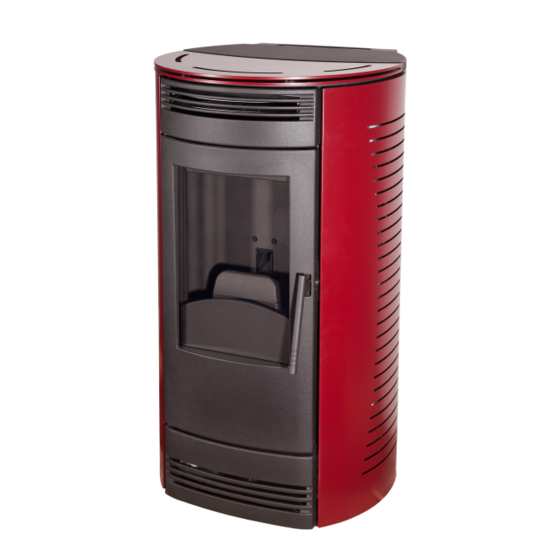
    2.2 DESCRIPTION TECHNIQUE Le poêle EQ 10 a été conçu pour chauffer les locaux d’habitation ou pour améliorer un chauffage insuffisant tout en décorant l’environnement. Le cœur du poêle, le socle, le haut ainsi que toutes les parties du foyer sont réalisées en fonte vernie ou émaillée. Ils résistent aux températures élevées.
  • Page 43: Données Techniques Et Dimensions

    2.3 DONNEES TECHNIQUES ET DIMENSIONS SCHEMA D’ENCOMBREMENT Evacuation postérieure ou supérieure pour version granulés et granulés canalisables DIMENSIONS (cm) 101,5 39,3 12,7 ø4 31,1 11,3 87,3 ø8...
  • Page 44: Modele De Poêle Eq

    CARACTERISTIQUES TECHNIQUES MODELE DE POÊLE EQ 10 Largeur Profondeur Hauteur Poids Diamètre du tuyau d’aspiration de l’air de combustion Diamètre du tuyau de canalisation Diamètre du tuyau d’évacuation des fumée Puissance thermique nominale Puissance thermique réduite m³ Volume chauffable max. (*) kg/h Consommation horaire combustible max.
  • Page 45 L’installation du poêle doit être effectuée après l’évaluation des différentes considérations d’ordre pratique. Les parois latérales du poêle doivent être en brique ou en béton ou être réalisées avec du matériel ignifugé ou protégé par du matériel isolant. Le poêle génère de la chaleur surtout à côté du foyer. Eviter alors de positionner à proximité un objet inflammable ou sensible à...
  • Page 46: Préparation Du Poêle

    3.2 PREPARATION DU POELE Après avoir décidé de l’emplacement du poêle, vous pouvez enlever l’emballage. Le poêle est emballé dans une caisse en bois avec un plancher rigide. Tout d’abord: • Retirer la caisse en carton. • Dévisser le plancher en bois afin de libérer le poêle. •...
  • Page 47: Exemple De Branchement Pour L'air Comburant

    à une association nationale spécialisée dans la construction des conduits d’évacuation de fumée dont le personnel qualifié a connaissances des mises à jour techniques et juridiques. Le technicien spécialisé devra se reporter au tableau ci-dessous: EQ 10 Modèle poêle Tirage minimum requis dans le conduit CO mesuré...
  • Page 48: Raccordement Fumees Et Conduit De Fumee

    3.5 RACCORDEMENT FUMEES ET CONDUIT DE FUMEE Le système d’évacuation de fumée du poêle fonctionne par effet de dépression qui se crée dans la chambre de combustion. Il est important que le système d’évacuation de fumée appelé ensuite raccordement fumée soit construit avec des matériaux certifiés avec les caractéristiques suivantes: •...
  • Page 49 L’extrémité du système d’évacuation doit être à une distance d’au moins 30 cm de la paroi extérieure, afin de garantir une évacuation correcte des fumées de combustion. fig. 5 Protecteur contre le vent Cheminée Externe Cheminée Isolé Inspection Inspection ATTENTION S’assurer que les règlements communaux ou des services sanitaires compétents par territoire n’obligent pas à...
  • Page 50: Extremite De L'installation De L'evacuation-Cheminee

    EXTREMITE DE L’INSTALLATION DE L’EVACUATION-CHEMINEE La cheminée est positionnée au sommet du conduit et sa fonction est: • D’évacuer dans l’atmosphère les résidus de la combustion • D’éviter l’accès à l’intérieur du conduit de neige, pluie ou tout autre corps étranger (feuilles emportées par le vent...) •...
  • Page 51: Dispositifs De Sécurité

    ATTENTION Le poêle a été conçu et testé pour fonctionner uniquement avec des granulés d’origine et de qualité certifiés. Le constructeur décline toute responsabilité en cas d’utilisation de granulés de qualité et de diamètre non adéquats ainsi que du mauvais fonctionnement en résultant. 4.3 DISPOSITIF DE SECURITE: Thermocouple: il est situé...
  • Page 52: Panneau De Commande

    ATTENTION N’UTILISER AUCUN LIQUIDE INFLAMMABLE PENDANT L’ALLUMAGE • PENDANT LA PHASE DE REMPLISSAGE NE PAS METTRE LE SAC DE GRANULE EN CONTACT AVEC LE • POELE TRES CHAUD 4.5 PANNEAU DE COMMANDE ECRAN TACTILE L’écran est commandé grâce à une série de touches tactiles. Voici la liste de ces touches: Menu température Touche Description...
  • Page 53: Reglage De La Temperature Et Chauffage Manuel/Automatique

    REGLAGE DE LA TEMPERATURE ET CHAUFFAGE MANUEL/AUTOMATIQUE 4.6) Le réglage de la température ambiante et la modification du chauffage manuel/automatique peuvent être effectuée par pression rapide de la touche 6 quand l’écran est en veille ou pendant la phase de chauffage.
  • Page 54: Menu Utilisateur

    4.7 MENU UTILISATEUR Pour entrer dans le menu utilisateur il est nécessaire d’appuyer sur la touche 6 quand l’écran est en veille ou pendant le chauffage jusqu’à la confirmation de l’entrée dans le menu par l’affichage: 1 – Nettoyage du poêle: démarrage automatique du nettoyage du poêle 2 –...
  • Page 55: Horloge

    4.9 HORLOGE Dans le menu les touches ont la signification suivante Touche Description des fonctions Sortie du menu sans sauvegarde du paramètre clignotant Paramètre suivant Paramètre précédent Diminution paramètre Augmentation paramètre Sauvegarde du paramètre clignotant et passage au suivant Les paramètres modifiables à l’intérieur du menu horloge sont: Minutes Journée Heure...
  • Page 56: Chronothermostat

    4.11 Chrono thermostat du menu il t possible de choisir jusqu’à 10 différents programmes. l’intérieur Après avoir choisi avec les touches 4 et 5 la tranche horaire et avoir confirmé votre choix avec la touche 6, les touches on t la signification suivante: Touche Description de la fonction Sortie du menu sans sauvegarde du paramètre clignotant...
  • Page 57: Mise À L'arrêt

    4.12 Mise à l'arrêt Appuyez sur la touche pendant deux secondes afin d’éteindre le poêle et la procédure de mise à l’arrêt s’activera. Ne jamais débrancher l’alimentation électrique pendant la mise à l’arrêt car le ventilateur et le moteur d’extraction de fumées continuent de fonctionner jusqu’à...
  • Page 58: Vitre Panoramique

    SUPERFICIE EXTERNE Utiliser un torchon souple et des détergents liquides à base neutre pour les parties en céramique. Les parties extérieures en fonte émaillées doivent être dépoussiérées au moyen d’un torchon doux et sec. N’utilisez jamais d’éponge abrasive ou métallique afin de ne pas abîmer les superficies. VITRE PANORAMIQUE La vitre panoramique est autonettoyante, c’est-à-dire pendant le fonctionnement du poêle, l’air souffle sur la partie intérieur de la vitre en empêchant le dépôt de cendres et de saletés.
  • Page 59: Nettoyage Du Déflecteur

    NETTOYAGE DU DÉFLECTEUR Dans le but de nettoyer les cendres déposées sur le déflecteur, il doit pouvoir vous vers le haut, en arrière. RÉCIPIENT BRULEUR A PELLETS (voir photo) Nous nettoyons le bruleur a pellets les deux côtés (fig. 1). Enlever le bruleur a pellets partie supérieure (fig.
  • Page 60: Centrale Électronique

    6.0 CENTRALE ELECTRONIQUE • DISPOSITION DE LA CENTRALE THERMOSTAT RÉARMEMENT MANUEL THERMOSTAT 120ºC PRESSOSTAT...
  • Page 61: Conseils En Cas De Problème

    CONSEILS EN CAS DE PROBLEME PROBLEME CAUSE POSSIBLE SOLUTION Absence de courant électrique Vérifier le branchement au réseau Interrupteur d’allumage éteint électrique Affichage défectueux Appuyer sur l’interrupteur à l’arrière du Branchement défectueux poêle Panneau de commandes éteint Fusible panneau électronique Contacter le centre d’assistance interrompu Contacter le centre d’assistance...
  • Page 62: Nettoyage Et Entretien

    Contacter le centre - Manque de pellets 007 - Pas d'allumage ------------------------------ d’assistance. - Basse température fumée La poêle s'allume quand le poêle - Panne de courant pendant 008 - Black Out Appuyer sur la touche 1 à nouveau être branché sur le une période supérieure à...
  • Page 63: Conditions De Garantie

    9. GARANTIE. Ecomasa World Investments, (ECOMASA) garanti ce produit pendant 2 (deux) ans à partir de la date d’acquisition, en cas de défaut de fabrication et de matériaux. La responsabilité d’Ecomasa se limite à la livraison du produit, qui doit être installé en conformité des lois en vigueur et suivant les indications du manuel d’utilisation.
  • Page 64: Exclusion De La Garantie

    • Surchauffe du poêle due à une combustion de matériaux qui ne concordent pas avec le type (pellet de bois) indiqué sur le manuel d’utilisation. • Transport du produit. Il est recommandé de contrôler minutieusement le produit à sa réception, en avertissant immédiatement le vendeur de la possibilité...
  • Page 65: Signature De L'acheteur

    EQ 10 LES DONNEES TECHNIQUES NE SONT PAS EXHAUSTIVES. L’ENTREPRISE SE RESERVE LE DROIT D’APPORTER TOUTE MODIFICATION AU PRODUIT SANS NOTIFICATION PREALABLE ET SELON LES EVOLUTIONS TECHNIQUES. Chauffe Modèle:……………………………………………. Date d'achat:……………………………………………. Seal Company vendeur: Signature de l'acheteur: Mise en service: Seal S.A.T.
  • Page 66 DÉCHETS L'élimination appropriée du produit. 2002/95/CE, 2002/96/CE y 2003/108/CE (Applicable dans tous les pays de l'UE et les pays avec des systèmes de collecte sélective) À la fin du cycle de vie, le produit doit être la mise en décharge et ne pas être dispersés dans l'environnement.
  • Page 67 MANUALE INSTALLAZIONE, USO E MANUTENZIONE STUFA A PELLET EQ 10 Egregio cliente, grazie per aver scelto un prodotto Ecomasa World Investments. Questo prodotto, curato in tutte le sue parti, è stato progettato e realizzato al fine di soddisfare al meglio le Vostre esigenze di funzionalità...
  • Page 68 INDICE 1. Avvertenze e sicurezza 1.1 Avvertenze 1.2 Avvertenze e sicurezza 2. Caratteristiche tecniche 2.1 Accessori in dotazione 2.2 Descrizione tecnica 2.3 Dati tecnici e dimensioni 3. Installazione 3.1 Regole generali 3.2 Preparazione della stufa 3.3 Collegamento alla presa d’aria esterna 3.4 Sistema di evacuazione fumi 3.5 Raccordo fumi e canna fumaria 3.6 Tubi da utilizzare...
  • Page 69 PREMESSA » Il presente manuale è stato redatto dal costruttore e deve essere considerato parte integrante del prodotto. Le informazioni in esso contenute devono essere prese in visione sia dal personale non qualificato che dal personale tecnico incaricato di intervenire sul prodotto. »...
  • Page 70: Avvertenze E Sicurezza

    1. AVVERTENZE E SICUREZZA 1.1 Avvertenze Prima di utilizzare la stufa si consiglia di leggere integralmente il seguente manuale - Prima della messa in funzione della stufa, accertarsi del corretto inserimento di tutti i componenti: crogiolo (parte inferiore e parte superiore), deflettore in ghisa e cassetto cenere come riportato nel seguente manuale. - Prima di ogni accensione accertarsi che il crogiolo sia posizionato correttamente, che non sia intasato di cenere, che la presa di corrente sia inserita in modo corretto e che lo sportello sia ben chiuso;...
  • Page 71: Per La Sicurezza È Bene Ricordare Che

    • In qualità di utilizzatore della stufa deve essere ammessa una persona adulta e responsabile provvista delle conoscenze tecniche necessarie per la manutenzione ordinaria dei componenti meccanici ed elettrici della stufa. Fare attenzione che i bambini non si avvicinino alla macchina, mentre è in funzione, con l’intento di giocarvi. •...
  • Page 72: Caratteristiche Tecniche

    2.0 CARATTERISTICHE TECNICHE Modello EQ 10 P SP La sigla “P” significa pellet, l a sigla “SP” significa scarico posteriore. 2.1 ACCESSORI IN DOTAZIONE Prima di installare la stufa controllate che sia completa di tutti gli accessori in dotazione: Cavo elettrico di collegamento alla rete.
  • Page 73: Descrizione Tecnica

    2.2 DESCRIZIONE TECNICA La stufa EQ 10 è stata progettata per riscaldare locali di abitazioni o per migliorare un riscaldamento insufficiente, e nello stesso tempo arredando l’ambiente. Il cuore della stufa, il basamento, il top e tutte le parti del focolare sono realizzati in ghisa verniciata o smaltata resistente alle alte temperature, la struttura portante in lamiera zincata d’acciaio nervato, il rivestimento laterale in ceramica o...
  • Page 74: Dati Tecnici E Dimensioni

    2.3 DATI TECNICI E DIMENSIONI LE DIMENSIONI DI CONTORNO Scarico posteriore applicabile alla versione pellet INGOMBRI (Cm) SALIDA POST. MEDIDA 101,5 39,3 12,7 ø4 31,1 11,3 87,3 ø8...
  • Page 75: Installazione

    CARATTERISTICHE TECNICHE: MODELLO STUFA EQ 10 Larghezza Profondità Altezza Peso Diametro tubo aspirazione aria combustione Diametro tubo canalizzazione Diametro tubo scarico fumi Potenza termica nominale Potenza termica ridotta 3’4 Volume riscaldabile max. (*) m³ Consumo orario combustibile max. kg/h Consumo orario combustibile min.
  • Page 76 L'installazione della stufa deve essere fatta valutando diverse considerazioni di ordine pratico. Le pareti adiacenti alla stufa devono essere costruite in mattoni o calcestruzzo, oppure essere realizzate con materiali incombustibili o opportunamente protette con materiali isolanti. La stufa genera calore soprattutto in prossimità del focolare, per cui non posizionare in sua vicinanza nessun oggetto infiammabile o fortemente sensibile al calore (es.
  • Page 77: Preparazione Della Stufa

    3.2 PREPARAZIONE DELLA STUFA Individuata la posizione ottimale della stufa si può togliere l’imballo. La stufa è imballata in una gabbia di cartone con pianale. Per prima cosa dobbiamo: Togliere la gabbia in cartone. • Svitare le viti sotto la pedana in legno per liberare la stufa. •...
  • Page 78: Sistema Di Evacuazione Fumi

    (Associazione Nazionale Fumisti e Spazzacamini tel. 06/39388501), i cui associati sono personale qualificato ed aggiornato in materia. Il tecnico specializzato, per l'installazione prodotto dovrà riferirsi alla seguente tabella: Modello stufa EQ 10 Requisiti minimi di tiraggio del camino CO misurato al 13% di ossigeno Temperatura media gas di scarico °C...
  • Page 79: Raccordo Fumi E Canna Fumaria

    3.5 RACCORDO FUMI E CANNA FUMARIA Il sistema di uscita dei fumi dalla stufa funziona per effetto della depressione che si crea nella camera di combustione. E' molto importante che il sistema di uscita dei fumi nella parte denominato "raccordo fumi" sia costruito con materiali certificati e abbia almeno le seguenti caratteristiche: siano ermeticamente sigillati, quindi è...
  • Page 80 Il terminale di scarico deve essere ad una distanza dalla parete esterna di almeno 30 cm, ciò per garantire una corretta evacuazione in atmosfera dei fumi di combustione. fig. 5 ATTENZIONE Accertarsi che il regolamento comunale o di azienda sanitaria, territorialmente competenti del comune di installazione della stufa, non impongano l'uscita dei fumi attraverso la canna fumaria a tetto.
  • Page 81: Parte Terminale Dell'impianto Di Scarico-Comignolo

    3.8 PARTE TERMINALE DELL'IMPIANTO DI SCARICO – COMIGNOLO Il comignolo è posto alla sommità del camino e sovrintende alle funzioni sotto elencate: Smaltire in atmosfera i residui della combustione. • Evitare l'accesso all'interno del camino di pioggia, neve o qualsivoglia corpo estraneo (foglie portate del vento, •...
  • Page 82: Dispositivi Di Sicurezza

    ATTENZIONE La stufa è stata progettata e collaudata per funzionare solo ed esclusivamente con pellets di certificata qualità. l produttore non si assume alcuna responsabilità per l'utilizzo di pellets di qualità non adeguata e non ne risponde per il conseguente mal funzionamento della stufa. 4.3 DISPOSITIVI DI SICUREZZA: Termocoppia: posta sullo scarico fumi che ne rileva la temperatura.
  • Page 83: Funzionamento

    ATTENZIONE NON UTILIZZARE ALCUN LIQUIDO INFIAMMABILE PER L'ACCENSIONE • IN FASE DI RIEMPIMENTO NON PORTARE IL SACCO DI PELLET A CONTATTO CON LA STUFA BOLLENTE • 4.5 PANNELLO DI COMANDO TASTIERA La scheda è comandata tramite una serie di tasti a sfioramento elenchiamo di seguito le descrizioni: Set temperatura am- Tasto Descrizione...
  • Page 84: Impostazione Temperatura Ambiente E Riscaldamento Manuale/Automatico

    4.6) IMPOSTAZIONE TEMPERATURA AMBIENTE E RISCALDAMENTO MANUALE/AUTOMATICO L'impostazione della temperatura ambiente e la modifica del riscaldamento manuale/automatico può essere effettuata con due pressioni veloci del tasto 6 quando la scheda è in “attesa” o durante il riscaldamento. In questo caso i tasti assumono il seguente significato: Tasto Descrizione funzionalità...
  • Page 85: Menù Utente

    4.7 MENÙ UTENTE Per entrare nel menù utente è necessario tener premuto il tasto 6 quando la scheda è in “attesa” o durante il riscaldamento finché non viene confermato a display l'entrata nel menù. Le voci presenti nel menù utente sono: 1 –...
  • Page 86: Orologio

    4.9) OROLOGIO All'interno del menù i tasti assumono il seguente significato: Tasto Descrizione funzionalità Uscita dal menù senza salvataggio del parametro lampeggiante Parametro successivo Parametro precedente Diminuisce parametro Aumenta parametro Salvataggio parametro lampeggiante e passaggio al successivo I parametri modificabili all'interno del menù orologio sono: 4.10) OPZIONI All'interno del menù...
  • Page 87 4.11) PROGRAMMATORE SETTIMANALE (CRONOTERMOSTATO) All'interno del menù si possono scegliere fino a 10 fasce orarie. Dopo aver scelto con i tasti 4 e 5 la fascia oraria di interesse e aver confermato con il tasto 6 la scelta, i tasti assumono il seguente significato: Tasto Descrizione funzionalità...
  • Page 88: Spegnimento

    4.12 Spegnimento: A stufa accesa tenere premuto il tasto 1 per almeno 2 secondi e si avvierà la procedura di spegnimento. Non togliere mai la corrente elettrica durante lo spegnimento perché i motori ventilazione e motore estrazione fumi continuano a funzionare fino a quando la sonda fumi rileva la temperatura di sicurezza impostata.
  • Page 89: Pulizia E Manutenzione

    5.0 PULIZIA E MANUTENZIONE Una manutenzione accurata della stufa e della canna fumaria ne manterrà alta l'efficienza e la sicurezza. ATTENZIONE • Prima di effettuare qualsiasi operazione di pulizia e manutenzione, attendere che la stufa e i tubi di collegamento alla canna fumaria si siano raffreddati completamente. •...
  • Page 90 VETRO PANORAMICO Il vetro panoramico è autopulente, ovvero mentre la stufa è in funzione, un velo d'aria lambisce la parte interna del vetro stesso diminuendo notevolmente il deposito di cenere e sporcizia. E’ possibile comunque che dopo alcune ore di funzionamento il vetro si sporchi internamente, ciò in virtù del tipo di pellet utilizzato e del tiraggio della canna fumaria.
  • Page 91 PULIZIA DEL DEFLETTORE Con lo scopo di pulire la cenere depositata sul deflettore, deve potenza si verso riba, anteriore e posteriore. CIOTOLA DI BRUCIATORE A PELLET (vedi foto) Puliamo su entrambi i lati (fig. 1) bruciatore a pellet. Rimuovere il bruciatore a pellet parte superiore (fig. 2). Rimuovere la parte inferiore del bruciatore di pellet (fig.
  • Page 92: Centralina Elettronica

    6.0 CENTRALINA ELETTRONICA • LAY-OUT CENTRALINA TERMOSTATO RIARMO MANUALE TERMOSTATO 120ºC PRESSOSTATO...
  • Page 93: Consigli In Caso Di Inconveniente

    CONSIGLI IN CASO DI INCONVENIENTE PROBLEMA CAUSA POSSIBILE SOLUZIONE Manca alimentazione elettrica Controllare spina e presenza energia elettrica Interruttore accensione spento Agire sull’interruttore posteriore per azionarlo Display difettoso Contattare il centro assistenza Pannello di comando spento Cavo collegamento difettoso Contattare il centro assistenza Fusibile scheda interrotto Contattare il centro assistenza Scheda difettosa...
  • Page 94 - Abbassamento della Contattare il centro 007 - No Fiamma temperatura fumi al di sotto ------------------------------ assistenza. del valore di "Fire On" - Mancanza energia elettrica per La pantalla se encenderá cuándo 008 - Black Out Pressione del tasto 1 un periodo superiore a quello la estufa vuelva a estar conectada fissato per il black out.
  • Page 95: Garanzia

    IL PRODUTTORE DECLINA OGNI RESPONSABILITA’ PER DANNI A PERSONE, ANMALI O COSE CAUSATI DALLA NON ADEMPIENZA DELLE NORME GENERALI DI SICUREZZA ED ALLE ISTRUZIONI D’USO , PULIZIA E DI MANUTENZIONE ELENCATE IN QUESTO MANUALE EQUATION Ecomasa World Investments, S.L.U. Pol. Ind. La Cerrada, 14 39600 Maliaño (Cantabria) – ESPAÑA...
  • Page 96 EQ 10 DATI TECNICI NON SONO EXHASUSTIVOS. IL COSTRUTTORE SI RISERVA IL DIRITTO DI APPORTARE MODIFICHE AL PRODOTTO SENZA PREAVVISO E COME GLI SVILUPPI TECNICI. Riscaldatore Modello:……………………………………………. Data di acquisto:……………………………………………. Compagnia Seal venditore: Firma del Committente: Start-Service: Timbro S.A.T. Data:………………………………..
  • Page 97 RIFIUTI Il corretto smaltimento del prodotto. 2002/95/CE, 2002/96/CE y 2003/108/CE (Applicabile in tutti i paesi e paesi europei con sistema di raccolta differenziata) Al termine del ciclo di vita, il prodotto deve essere la discarica e non essere dispersi nell'ambiente. Per evitare possibili danni all'ambiente o alla salute causati da uno smaltimento improprio, viene richiesto all'utente di rimuovere tutte le parti del prodotto ed eventualmente gettare ciascuno dei materiali.
  • Page 98 INSTALLATION, USAGE AND MAINTENANCE MANUAL FOR PELLET STOVE MODEL EQ 10 Dear Customer, first of all to thank you for having purchased a product from Ecomasa World Investments This product has been designed in all its parts with the goal to meet all your requirements of use and safety.
  • Page 99 TABLE OF CONTENTS 1. Safety Warnings 1.1 Warnings 1.2 Safety warnings 2. Technical Characteristics 2.1 Accessories 2.2 Technical Description 2.3 Technical data and dimensions 3. Installation 3.1 General recommendations 3.2 Stove preparation 3.3 External air intake 3.4 Release of smoke system 3.5 Smoke connection and chimney 3.6 Tube to be used 3.7 Installation identification scemes...
  • Page 100 PROLOGUE » This manual has been drawn up by the manufacturer and should be considered as part of the product. The information reflected in this manual must be taken into consideration by the user, as well as by the technical staff responsible for the installation, maintenance and handling of the product.
  • Page 101: Safety Warnings

    1. SAFETY WARNINGS 1.1 Warnings Before using the stove for the first time please read carefully this manual. - Before using the stove for the first time, make sure that all accessories and components have been supplied: Crucible (top and bottom), the cast iron deflector for the ash, as described in this manual. - Before turning it on you must make sure that the crucible is in the correct position, is not full of ash and that the power supply is correctly plugged in, as well as ensuring that the door is securely closed.
  • Page 102 • The use of the stove should be done by an adult and responsible person, and with the expertise needed for the regular management of their components both mechanical and electrical. Make sure that children will not get close to the stove when it is turned on.
  • Page 103: Technical Characteristics

    2.0 TECHNICAL CHARACTERISTICS EQ 10 P SP The letter " P " means granulated, the letters SP mean rear evacuation. 2.1 INCLUDED ACCESSORIES Before the stove is installed, please verify that all accessories are included: Electrical wires for the connection.
  • Page 104: Technical Description

    2.2 TECHNICAL DESCRIPTION The stove EQ 10 has been designed to heat the environment or to improve the room temperature, at the same time that it is a decorative product. The fire site location has a panoramamic door manufactured in vitroceramic glass and it is resistant to high temperatures (700 °).
  • Page 105: Technical Data And Dimensions

    2.3 TECHNICAL DATA AND DIMENSIONS OUTLINE DIMENSIONS Upper or rear evacuation for a piped and granulated version. DIMENSIONS (cm) 101,5 39,3 12,7 ø4 31,1 11,3 87,3 ø8...
  • Page 106: Installation

    TECHNICAL CHARACTERISTICS AROLLA 10 STOVE MODEL Length Width High Weight Diameter of the suction pipe of the combustion air Conduction pipe diameter Smoke evacuation diameter Rated thermical power 3’5 Reduced thermical power Heating volume (máx.) m³ Maximum consum/fuel hour kg/h Minimum consum/fuel hour kg/h Storing capacity...
  • Page 107 The stove installation should be performed after evaluating different practical considerations. The side panels must be of brick or any other insulating or fire resistant material or protected by this type of material. The stove generates heat, especially next to the firesite. You should therefore avoid to have flammable or heat sensitive objects close by (ex. Alcohol, paper, plastic…).
  • Page 108: Stove Preparation

    3.2 STOVE PREPARATION Once determined the stove location, you can proceed to remove the packaging The oven is packaged in a wooden box with a rigid plate. Firstly: Remove the wooden box • Unscrew the wooden plank in order to release the stove •...
  • Page 109 National Association of specialists for the installation of this type of products as they will have detailed knowledge of the rules and all the technical and legal details. Specialized technicians must put attention to this table: Stove model EQ 10 Minimum length of pipe CO measured with 13% of oxygen Average temperature of evacuation gas °C...
  • Page 110: Installation Type

    3.5. SMOKE CONECTION AND CHIMNEY The smoke evacuation system is installed by means of pressure effect on the combustion chamber. It is important that this smoke evacuation system is correctly connected with specific materials and the following characteristics: Pipes must be sealed hermetically. It is therefore necessary to use steel tubes equipped with silicone joints. •...
  • Page 111 The end part of the evacuation system must have a minimum distance of 30cm from the exterior wall, in order to ensure a proper evacuation of smoke generated by combustion. fig. 5 ATTENTION Ensure that Community regulations or the competent health services in the territory or do not obligate the application of additional standards.
  • Page 112: Connection To The Power Supply

    CHIMNEY The chimney is placed at the end of the pipe and its function is: Evacuate the combustion residues to the exterior. • • Avoid the entrance of rain or other objects into the smoke evacuation pipe Guarantee the combustion even if it is windy. •...
  • Page 113: Safety Device

    ATTENTION The stove has been designed to work only with original and quality pellet. The manufacturer declines all responsibility in the case of using low quality pellet and a not adequate diameter which may cause a malfunction. 4.3 SAFETY DEVICE: Thermocouple: located in the exhaust smoke pipe which increases the temperature.
  • Page 114: Control Panel

    ATTENTION • DO NOT USE ANY FLAMMABLE FLUIDS DURING THE POWER ON DURING THE PELLET LOADING PHASE, DO NOT PUT THE PELLET BAG IN CONTACT WITH THE HOT • SURFACE OF THE STOVE 4.5 CONTROL PANEL TOUCHSCREEN The screen utilization is made through touch screen keys. In the following you will find the use of each button: Description Operation Room temperature menu...
  • Page 115: Temperature Control: Manual And Automatic

    4.6. TEMPERATURE CONTROL: MANUAL AND AUTOMATIC Temperature control and its modification can be done manually or automatically, and can be performed by pressing key No. 6 when the display is in standby mode or in the heating phase. In this case one must press the following keys: Function description Exit from the temperature menu and modify the manual / automatic temperature...
  • Page 116: User Menu

    4.7. User menu. In order to enter in the user menu is necessary to press key 6 when the screen is in stand by mode or during the heating. 1 – Stove cleaning: Activation of stove auto cleaning. 2 – Clock: time and date set up . 3 –...
  • Page 117: Clock

    4.9. CLOCK In the menu, the keys have the following meaning: Function description Exit from menu without saving parameters Next parameter Previous parameter Decrease of parameters Increase of parameters Save parameters and go to the next one Parameters that can be modified in the timetable menu are the following: 4.10.
  • Page 118 4.11. THERMOSTATE PROGRAMMING In the menu it is possible to choose from 10 time zones. After choosing the time with keys 4 and 5 and confirming by key 6, the keys take following meaning: Function description Exit from menu without saving changes Next Previous Parameter decrease...
  • Page 119: Switching Off

    4.12 Switching off Press the off button for two seconds in order to turn off the stove. The closing process is activated at this time. Do not unplug the stove from the power supply during the closing process since a fan and a smoke extraction engine continue in operation until a probe detects that there is no smoke and there is a proper safety temperature.
  • Page 120: Automatic Cleaning

    5.0 CLEANING AND MAINTENNACE The cleaning and maintenance operations guarantee a smooth operation of this product over time. ATTENTION • Before cleaning, check that the stove and the connection pipes are completely cold. For cleaning never use flammable products. • 5.1 AUTOMATIC CLEANING The stove is equipped with an automatic cleaning system in stead of the manual cleaning system Press key 6 during approximately 2 seconds and enter into the user menu.
  • Page 121 PANORAMIC GLASS The panoramic glass is cleaned by itself during the stove operation; the air touches the inside part of the glass and clean it from ash and particles. Is it possible that after working for several hours the glass is dirty inside. This may be due to the quality of the pellets used as well as a bad circulation of the smoke exit.
  • Page 122 CLEANING OF THE DEFLECTOR With the aim of cleaning the ash deposited on the deflector, it must power you towards riba, front and back. PELLET BURNER BOWL (see photo) We clean on both sides (fig. 1) pellet burner. Remove the upper part (fig. 2) pellet burner. Remove the bottom of the burner of pellet (fig.
  • Page 123 6.0 ELECTRONICAL CIRCUIT • ELECTRONICAL CIRCUIT DISPOSITION THERMOSTAT MANUAL REARMAMENT THERMOSTAT 120ºC PRESSURE SWITCH...
  • Page 124: Trouble-Shooting

    7.0 ADVICES TROUBLE-SHOOTING ISSUE POSSIBLE REASON SOLUTION Lack of power Verify electrical connections Turning on/Switch off button is switched Press button placed in the rear area of the stove Contact technical assistance Faulty screen Control Panel switched off Contact technical assistance Faulty connection Contact technical assistance Fuse not operational in electronical panel...
  • Page 125 - Lack of pellets. Contact the technical 007 - Flame problem - Température de la fumée ------------------------------ assistance center. très basse. - Lack of electricity more Display will turn on when To reload press key 1 008 - Black Out than 5 s.
  • Page 126: Warranty

    THE MANUFACTURER DECLINES ALL RESPONSIBILITY IN CASE OF DAMAGE TO PERSONS, ANIMALS OR OBJECTS CAUSED BY NOT RESPECTING THE GENERAL RULES OF SAFETY DESCRIBED IN THIS USE, CLEANING AND MAINTENANCE GUIDE. EQUATION Ecomasa World Investments, S.L.U. Pol. Ind. La Cerrada, 14...
  • Page 127 EQ 10 ECHNICAL DATA ARE NOT EXHAUSTIVAS. THE MANUFACTURER RESERVES THE RIGHT TO MAKE CHANGES TO THE PRODUCT WITHOUT NOTICE AND TECHNICAL DEVELOPMENTS. Stove Model:……………………………………………. Date of purchase:……………………………………… Selling Company Seal: Signature of Buyer: Commissioning: Stamp S.A.T. Date:………………………………..
  • Page 128 WASTE Proper disposal of the product. 2002/95/CE, 2002/96/CE y 2003/108/CE (Applicable in all EU countries and countries with separate collection systems) At the end of the life cycle, the product must be the landfill and not be dispersed in the environment.
  • Page 129 EQUATION HANDLEIDING VOOR INSTALLATIE, GEBRUIK EN ONDERHOUD VAN DE PELLETKACHEL MODEL EQ 10 Onze welgemeende dank voor uw aankoop. Dit Ecomasa World Investments product is ontworpen zodat het aan alle eisen voor gebruik en veiligheid voldoet. Voor de installatie en gebruik van het apparaat is het belangrijk dat U deze handleiding doorleest.
  • Page 130 INDEX 1. Veiligheidsmaatregelen 1.1 Aanbevelingen 1.2 Veiligheidsadviezen 2. Technische kenmerken 2.1 Inbegrepen accessoires 2.2 Technische beschrijving 2.3 Technische gegevens en afmetingen 3. Installatie 3.1 Algemene regels 3.2 Voorbereiding van de kachel 3.3 Buitenlucht-inlaat 3.4 Rook uitlaatsysteem 3.5 Verbinding rook uitgang en schoorsteen 3.6 De te gebruiken buis 3.7 Illustratieve installatie diagrammen 3.8 De schoorsteen...
  • Page 131 VOORWOORD » Bewaar deze handleiding als een integraal onderdeel van het product .De inhoud van deze handleiding is belangrijk zowel voor de gebruiker als voor de technische service verantwoordelijk voor de installatie en onderhoud van het apparaat. » Deze handleiding bevat alle benodigde informatie voor een correcte installatie en gebruik van het product. »...
  • Page 132: Veiligheidsmaatregelen

    1. VEILIGHEIDSMAATREGELEN 1.1 Aanbevelingen We raden U aan deze handleiding zorgvuldig door te lezen voor het eerste gebruik van de kachel. - Controleer de aanwezigheid van al de inbegrepen accessoires en onderdelen voor de eerste ontsteking: smeltkroes (onderste en bovenste) ,de dispenser van gietijzer voor de as, zoals het in deze handleiding beschreven wordt. - Voor het aanzetten van de kachel controleer dat de smeltkroes in de juiste positie geplaatst is en dat die niet vol zit met as, controleer tevens dat de elektrische aansluiting correct is en de deur goed is gesloten.
  • Page 133 • De fabrikant aanvaardt geen aansprakelijkheid voor directe of indirecte schade aan personen, voorwerpen of huisdieren als gevolg van het niet volgen van de voorschriften van deze handleiding. • Controleer bij het openen van de verpakking of alle inbegrepen onderdelen aanwezig zijn. Bij ontbreken van onderdelen vraag dan deze aan bij uw dealer.
  • Page 134: Technische Kenmerken

    2.0 TECHNISCHE KENMERKEN Model EQ 10 P SP De letter « P » betekent granulaat, de letters SP betekenen achterste evacuatie 2.1 INBEGREPEN ACCESSOIRES Het is aan te bevelen de aanwezigheid van de inbegrepen accessoires na te kijken voor het installeren van de kachel:...
  • Page 135 2.2 TECNISCHE BESCHRIJVING De kachel model EQ 10 is ontworpen om warme lucht in de kamer te verspreiden en tegelijkertijd wordt het als een decoratief element beschouwd. De verbrandingskamer bezit een deur met keramische glaspanelen die resistent zijn voor hoge temperaturen (700 centigraden) en een hermetisch sluitingssysteem.
  • Page 136 2.3 TECHNISCHE KENMERKEN EN AFMETINGEN AFMETINGEN VAN DE OMTREK Boven of achteruitgang voor de pellet versie of de gegranuleerde geleiding. AFMETINGEN (cm) 101,5 39,3 12,7 ø4 31,1 11,3 87,3 ø8...
  • Page 137: Technische Gegevens

    TECHNISCHE GEGEVENS AROLLA 10 KACHEL MODEL Lengte Breedte Hoogte Gewicht Diameter rook-afzuigbuis van de verbranding Diameter leidingbuis Diameter van de rookgassen evacuatie buis Nominaal thermisch vermogenl Verminderd thermisch vermogen 3’5 Volume van opwarming(max.) m³ Maximale verbruik per uur van brandstof kg/h Minimale verbruik per uur van brandstof kg/h...
  • Page 138 De kachel genereert warmte, nadat alle verschillende praktische punten zijn doorgenomen. De zijpanelen dienen van baksteen of gelijksoortig isolatiemateriaal te zijn. De kachel genereerd warmte, vooral in de omgeving van de verbrandingskamer. Daarom dient men te voorkomen dat ontvlambare voorwerpen en vloeistoffen in de nabijheid van de kachel komen (alcohol, papier, plastic...). De kachel moet geïnstalleerd worden met in achtneming van de bijgevoegde normen.
  • Page 139: Voorbereiding Van De Kachel

    3.2 VOORBEREIDING VAN DE KACHEL Eenmaal de plaats gekozen waar de kachel geïnstalleerd gaat worden, kunt U de verpakking verwijderen. De kachel wordt geleverd in een houten doos met een harde plaat. Ten eerste: Verwijder de houten doos • • Maak de houten plank los om de kachel eruit te halen •...
  • Page 140: Rookuitlaatsysteem

    Ze zullen op de hoogte zijn van alle normen en technische-, juridische aspecten. Dit schema is van belang voor de gespecialiseerde technici: Kachel Model EQ 10 Minimale trekkingskracht voor de buis CO afgemeten met 13% zuurstof Gemiddelde temperatuur van de uitgelaten gassen °C...
  • Page 141: Verbinding Rookuitgang En Schoorsteen

    3.5 VERBINDING ROOKUITGANG EN SCHOORSTEEN Het rookuitgang-systeem wordt geïnstalleerd door een druk effect op de verbrandingskamer te produceren. Het is belangrijk dat dit systeem goed verbonden is met de specifieke materialen en dat het aan de volgende regels voldoet: • De buizen moeten hermetisch dicht zijn, daarom is het nodig om ijzeren buizen te gebruiken die verbonden worden met silicone.
  • Page 142 Het rookuitlaatsysteem moet geplaatst worden op een afstand van tenminste 30cm van de buitenmuur ,om een goede afvoer van de rook te garanderen. fig. 5 LET OP Verzeker U ervan dat er geen plaatselijke verordeningen zijn die van invloed zijn op de landelijke wetgeving ! Bij het installeren van de kachel binnen een complex (flat) dient U autorisatie aan te vragen bij de vereniging van eigenaren...
  • Page 143: De Schoorsteen

    3.8 DE SCHOORSTEEN De schoorsteen is geplaatst aan het einde van de buis en zijn functie is: • Het afvoeren van de rook naar de atmosfeer • Het voorkomen van het binnentreden van regenwater en andere voorwerpen in de rookafvoerbuis •...
  • Page 144: Veiligheidssysteem

    LET OP De kachel functioneert uitsluitend met originaal en van eerste kwaliteit pellet. De fabrikant aanvaardt geen aansprakelijkheid in geval dat er pellet van slechte kwaliteit wordt gebruik of met een onjuist diameter ,waardoor een slechte werking van de kachel zou kunnen ontstaan. 4.3 VEILIGHEIDSYSTEEM Termopar: deze is geplaatst in de rookafvoerbuis die de temperatuur laat oplopen en controleert het proces •...
  • Page 145: Configuratiescherm

    LET OP GEBRUIK GEEN ONTVLAMBARE VLOEISTOFFEN TIJDENS DE ONTSTEKING VAN DE KACHEL • GEDURENDE DE OPLADING VAN DE PELLETS. VOORKOM HET CONTACT VAN DE PELLETZAK MET DE WARME OPPERVLAKTE VAN DE KACHEL 4.5 DISPLAY CONFIGURATIESCHERM Hieronder kunt U de beschrijving van het toetsenbord vinden: Menú...
  • Page 146: Instellen Van De Temperatuur. Handmatig En Automatisch

    4.6. HET INSTELLEN VAN DE TEMPERATUUR: HANDMATIG EN AUTOMATISCH De temperatuur kan zowel handmatig als automatisch ingesteld worden. Om het uit te voeren druk toets nº6 in wanneer het scherm op” stand by “staat of in verwarming fase. In dit geval moeten we de volgende toetsen indrukken: Toets Beschrijving van de functie...
  • Page 147: Gebruikersmenu

    4.7. Gebruikersmenu Voor de optie “gebruikersmenu” druk op toets 6. Het toetsenbord is als volgt ingesteld: 1 – Reiniging van de kachel ( Automatische reiniging) 2 – Klok :instelling van datum en tijd. 3 – Opties :parameters die aangepast kunnen worden door de gebruiker. 4 –...
  • Page 148: Klok

    4.9. KLOK De betekenis van de toetsen : Toets Beschrijving van de functies Uit het menu (parameters zijn niet opgeslagen) Volgende parameter Voorafgaande parameter Afname van de parameters Toename van de parameters Opslaan van de parameters en doorgaan De verschillende parameters van de klok zijn: 4.10.
  • Page 149 4.11. HET INSTELLEN VAN DE THERMOSTAAT Er bestaat de mogelijkheid 10 verschillende tijdschema ‘s in te stellen. Kies het tijdschema met toets 4 en 5 ,en bevestig je keuze met toets 6.De betekenis van de toetsen is de volgende: Toets Beschrijving van de functie Uit het menu (wijzigingen niet opgeslagen) Volgende...
  • Page 150: Uitzetten Van De Kachel

    4.12 Uitzetten van de kachel Druk gedurende twee seconden op de toets “uit” om de kachel uit te zetten .Haal de stekker niet uit het stopcontact tijdens het uitzetten, omdat de ventilator en het rookafzuigsysteem nog even blijven functioneren totdat de sonde geen lucht meer detecteert en de juiste veilige temperatuur is bereikt..
  • Page 151: Reiniging En Onderhoud

    5.0 REINIGING EN ONDERHOUD Een correcte uitvoering van de reiniging en onderhoud zal het goed functioneren van het product waarborgen. LET OP Controleer dat de kachel en de rookuitlaatbuizen afgekoeld zijn voor het reiningen van het apparaat. • • Gebruik nooit ontvlambare schoonmaakmiddelen. 5.1 AUTOMATISCHE REINIGING De kachel bevat een automatisch reinigingssysteem .
  • Page 152 PANORAMISCHE GLAS Het panoramisch glas wordt vanzelf schoongemaakt tijdens het functioneren van de kachel ,de lucht komt in aanraking met de binnenkant van het glas en verwijdert het as en de partikels. Het is mogelijk dat het glas vuil wordt na enkelen uren van werking van de kachel. De oorzaak hiervan kan de kwaliteit van het gebruikte pellet zijn of een verkeerde druk bij het rook afvoer .In dit geval maakt u het glas schoon met een doek van katoen en gassenwasser .Hiervoor moet de kachel helemaal afgekoeld zijn.
  • Page 153 SCHOONMAKEN VAN DE DEFLECTOR Met het doel van het schoonmaken van de as gestort op de deflector, moet het macht je naar riba, voorste en terug. PELLET-BRANDER BOWL (zie foto) We schoon op beide zijden (fig. 1) pellet brander. Verwijder de bovenste deel (fig. 2) pellet brander. Verwijder de onderkant van de brander van pellet (fig.
  • Page 154: Elektronisch Circuit

    6.0 ELEKTRONISCH CIRCUIT OPSTELLING VAN HET ELEKTRONISCH CIRCUIT THERMOSTAAT REARME MANUAL THERMOSTAAT 120ºC DRUKSCHAKELAAR...
  • Page 155: Aanbevelingen Bij Storing

    7. Aanbevelingen bij storing PROBLEEM MOGELIJKE OORZAAK OPLOSSING Elektrische stroom ontbreekt Controleer de elektrische aansluiting Knop aan/uit Druk op knop geplaatst achteraan de Beschadigd scherm kachel Gebrekkige aansluiting Neem contact op met de technische dienst Display staat uit Uitvallen van de zekering van de Neem contact op met de technische dienst elektronische display Neemt contact op met de technische dienst...
  • Page 156 - Mangelan Pellets. KontaktierenSie das 007 - Flamen ausfall - Temperatur des Rauchessehr ------------------------------ technischeHilfeZentrum. gering. Das Displaywirdaktiviert, - KeinStromwährend 008 - Black Out Fürrucksezung taste 1 drücken. wenn Ofenwieder einZeitraum von mehrals 5s. mitdemNetzangeschlossenist. DRUCK nichtaktiviert: - OffeneTür. - VerstopfterKamin, schlechtes laufen des Schornsteins, ReinigenSie den Ofen.
  • Page 157: Garantie

    DE FABRIKANT AANDVAART GEEN AANSPRAKELIJKHEID VOOR DIRECTE OF INDIRECTE SCHADE AAN PERSONEN,VOORWERPEN OF HUISDIEREN ALS GEVOLG VAN HET NIET NALEVEN VAN DE ALGEMENE VEILEGHEIDSVOORSCHRIFTEN BESCHREVEN IN DEZE HANDLEIDING VAN GEBRUIK,REINIGING EN ONDERHOUD. EQUATION Ecomasa World Investments, S.L.U. Pol. Ind. La Cerrada, 14 39600 Maliaño (Cantabria) – ESPAÑA...
  • Page 158 EQ 10 TECHNISCHE GEGEVENS NIET EXHAUSTIVOS. DE FABRIKAN HET RECHT VOOR OM HET PRODUCT ZONDER AANKONDIGING EN ALS DE TECHNISCHE ONTWIKKELINGEN MAKEN. Model Heater:……………………………………………. Datum van aankoop:……………………………………… Company Seal verkoper: Handtekening van de Inkoper: Ingebruikname: Seal S.A.T. Datum:………………………………………………...
  • Page 159 AFVAL Juiste afvoer van het product. 2002/95/CE, 2002/96/CE y 2003/108/CE (Van toepassing in alle EU-landen en landen met gescheiden inzameling) Aan het eind van de levenscyclus moet het product de stortplaats en niet gedispergeerd worden in het milieu. Om mogelijke schade aan het milieu of de gezondheid als gevolg van ongecontroleerde verwijdering te voorkomen, wordt de gebruiker gevraagd om alle delen van het product en zo mogelijk te gooien elk van de materialen te verwijderen.

Table des Matières