Table des Matières
Publicité
Les langues disponibles
Les langues disponibles
Liens rapides
ManuaLe d'uso ScaLdacQua a poMpa di caLoRe
HeaT PuMp WaTeR HeaTeR useR ManuaL
ManueL d'uTiLisaTion chauFFe-eau À poMpe À chaLeuR
ManuaL de uso CaLenTadoR de agua con BoMBa de caLoR
GeBRuiKeRshandLeiding WaRMTepoMpBoiLeR
ModeLs:
Bollyterm
Home
®
www.cordivari.com
www.cordivaridesign.com
Cod. 1910000001165 - nv01
Publicité
Chapitres
Table des Matières

Manuels Connexes pour Cordivari Bollyterm Home


Sommaire des Matières pour Cordivari Bollyterm Home
- Page 1 ManuaLe d’uso ScaLdacQua a poMpa di caLoRe HeaT PuMp WaTeR HeaTeR useR ManuaL ManueL d’uTiLisaTion chauFFe-eau À poMpe À chaLeuR ManuaL de uso CaLenTadoR de agua con BoMBa de caLoR GeBRuiKeRshandLeiding WaRMTepoMpBoiLeR ModeLs: Bollyterm Home ® www.cordivari.com www.cordivaridesign.com Cod. 1910000001165 - nv01...
- Page 2 IT - Manuale d’uso BOLLYTERM HOME ....... . page ® EN - BOLLYTERM HOME User manual .
-
Page 3: Table Des Matières
Indice Italiano 1. Generalità ............pag. -
Page 4: Generalità
Italiano Manuale d’uso Bollyterm Home ® 1. Generalità ATTENZIONE! Se si avverte un rumore anomalo o strano 1.1 Simboli utilizzati odore o in caso di guasto e/o cattivo funzionamento, Il presente documento è parte integrante dell’apparecchio ed è destinato spegnere l’apparecchio, non tentare di ripararlo, ma all’installatore ed all’utilizzatore finale. Pertanto dopo l’installazione e l’avvio rivolgersi a personale autorizzato o qualificato. -
Page 5: Descrizione Prodotto
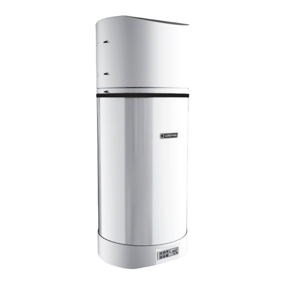
Italiano - disperdere, abbandonare o lasciare alla portata di bambini il 1.4 Caratteristiche costruttive materiale dell'imballo in quanto può essere potenziale fonte di Bollitore in acciaio con rivestimento Polywarm ® pericolo. • Condensatore avvolto esternamente al boiler esente da incrostazioni e contaminazione gas-acqua. -
Page 6: Norme
Italiano Pannello solare) che utilizzino acqua come fluido termovettore. Ogni Attenzione: l’inclinazione massima ammissibile per il utilizzo del prodotto diverso da quello indicato nel presente documento trasporto a brevi distanze è pari a 30°, per il trasporto solleva il costruttore da ogni responsabilità e comporta il decadimento di manuale non superare i 45°. -
Page 7: Dati Tecnici Del Prodotto
Italiano Installazione e Messa in servizio L’etichetta del prodotto contiene i seguenti dati tecnici, energetici ed identificativi del prodotto, sulla Pompa di Calore è apposta un’etichetta 7.1 Definizioni con numero di serie e codice a barre identificativi della pompa di calore: UTENTE - L'utente è... -
Page 8: Luogo Di Installazione
Italiano • Controllare che nell'imballo sia contenuta la documentazione. Nel caso in cui si utilizzi l’unità senza condotto di espulsione dell’aria, • Trasportare la sezione imballata il più vicino possibile al luogo di verificare che i locali abbiano un volume non inferiore ai 20 m . -
Page 9: Installazione Del Prodotto
Italiano 7.5 Installazione del prodotto 6) Assicurare il prodotto al muro fi ssando le staff e di sostegno ai • Togliere l’imballo dal prodotto, dispositivi di ancoraggio fi ssati alla parete. • Fissare il prodotto alla parete seguendo la sequenza indicata: 1) Assicurare le staff e di sostegno in dotazione all’apparecchio tramite le viti in dotazione 2) Selezionare il tipo di tassello ad espansione più... -
Page 10: Collegamenti Idraulici
Italiano dell'impianto su cui verrà installato l’apparecchio valutare, nel rispetto delle norme di installazione vigenti, lo schema impiantistico migliore per il 80 lt 110 lt suo utilizzo nel rispetto dei limiti imposti dai dati dichiarati dal costruttore. • Sulla base di quanto dettato dalla Circolare Ministeriale n. 829571 del 23/03/03 l’istallazione alla rete idrica domestica dei bollitori deve avvenire tramite un gruppo di sicurezza idraulica, comprendente almeno un rubinetto di intercettazione, una valvola di ritegno, un... -
Page 11: Resistenza Elettrica E Termostato A Riarmo Manuale
Italiano 7.8 Resistenza elettrica e termostato a riarmo manuale La resistenza elettrica è immersa nel bollitore attraverso il manicotto 1”1/4 sul fondo ed è dotata di un termostato di sicurezza a riarmo manuale. Per il riarmo manuale premere il pernetto bianco con una punta. Riarmo manuale Per la sostituzione del termostato a riarmo manuale: 1. - Page 12 Italiano • evitino il ricircolo di aria tra aspirazione e mandata della macchina; • siano adeguatamente protetti per evitare intrusioni accidentali di materiali all’interno della macchina. La canalizzazione va effettuata iniziando sempre il collegamento con il tronchetto dritto (accessorio elemento A). Attenzione: Non utilizzare griglie esterne che comportano elevate perdite di carico, come ad esempio griglie anti-insetti. Le griglie utilizzate devono permettere un buon passaggio dell’aria.
-
Page 13: Collegamenti Elettrici
Italiano • Per l'alimentazione generale della pompa di calore non è consentito l'uso di adattatori, prese multiple e/o prolunghe. • In caso di sostituzione di qualunque parte (compreso il cavo di alimentazione) utilizzare solo ricambi originali forniti dal costruttore. • E' dovere dell'installatore prevedere il montaggio il più vicino possibile all'unità... -
Page 14: Scheda Elettronica
Italiano Valvola a 4 vie Ventola Condensatore ventola Compressore Fusibile AC-N OUT5 OUT4 OUT3 Trasformatore Condensatore del OUT1 compressore OUT2 Resistenza Termostato a Scheda madre KEIN Centralina riarmo manuale Termostato T 80° C Switch di alta pressione Valvola di espansione TIME elettronica CN19... -
Page 15: Interfaccia Utente
Italiano TEMP WATER E R R O R • gestire le situazioni di allarme; TASTO [ON/OFF] • impostare i parametri modificabili dall'utente; All’avvio premendo una volta il tasto [ON/OFF] tutte le icone • verificare lo stato delle risorse. vengono visualizzate sullo schermo per 3 secondi poi si porta la macchina in STAND-BY. -
Page 16: Visualizzazione Parametri/Messaggi
Italiano TASTO [CLOCK] L’icona L6 [riscaldamento con pompa di calore] è accesa: la Consente di: pompa di calore è attiva e resta accesa finché la temperatura dell'acqua - impostare l’ora in modalità STANDBY o ON; rilevata dalla sonda T2 raggiunge il [valore impostato del parametro 0] - cancellare la funzione timer durante la programmazione TI- (set point PdC). -
Page 17: Impostazione Dell'orario
Italiano controllare sia la pompa di calore sia la resistenza elettrica. TEMP), la situazione del timer e l’ora. I parametri impostati, se non sono stati variati i valori, saranno quelli di default impostati dal costruttore. Da La resistenza elettrica è già cablata all’interno dell’unità, ai morsetti OUT 2 questo stato è... -
Page 18: Funzionamento Solo Resistenza Elettrica
Italiano Integrazione con Resistenza Elettrica 10.2.3 Funzionamento solo resistenza elettrica Durante la modalità funzionamento della Pompa Di Calore, la Resistenza La Resistenza Elettrica può funzionare da sola per riscaldare l'acqua nei Elettrica può funzionare come integrazione della pompa di calore nel seguenti casi: riscaldamento dell’acqua al fine di raggiungere la temperatura di set ATTIVAZIONE MANUALE: durante la modalità... -
Page 19: Funzione Trattamento Ciclico Antibatterico
Italiano A tale scopo, l’unità dispone della funzione TIMER che consente • Parametro 7 Temperatura scambiatore per attivazione sbrinamento -30 ~ 0°C (default -7°C) l’accensione/spegnimento ad un determinato orario • Parametro 8 Temperatura scambiatore per disattivazione sbrinamento Per impostare l’orario di accensione e di spegnimento premere il tasto 2 ~ 30°C (default 13°C) [TIMER] una volta, il quadrante orologio... -
Page 20: Navigazione/Impostazione Parametri
Italiano il riscaldamento dell’acqua sfruttando l’energia solare. A tale scopo bisogna regolare le temperature [Parametero 0 e parametro 2] alla minima temperatura richiesta dall’utenza (ad esempio 42°C); in questo modo la Pdc riscalda la parte superiore del bollitore solo fino a 8888 questa temperatura, consentendo al sistema solare di scaldare l’acqua fino a temperature più... -
Page 21: Tabella Dei Parametri
Italiano 10.3.1 Tabella dei parametri TABELLA PARAMETRI N° Descrizione Range Default Note Parametro Set point temp. Pompa Di Calore 10 ~ 70°C 50°C Modificabile Isteresi temperatura attivazione 2 ~ 15°C 5°C Modificabile Pompa Di Calore Set point temperatura spegnimento Modificabile 10 ~ 85°C 55°C resistenza elettrica (Non superare mai 75 °C) -
Page 22: Diagramma Complessivo Di Impostazioni Dei Parametri
Italiano 10.3.2 Diagramma complessivo di impostazioni dei parametri Diagramma complessivo di impostazione dei parametri (Seguire il seguente schema per visualizzare, modificare e impostare i parametri) STAND BY / RUN STAND BY / RUN STAND BY / RUN Parametri modificabili Parametri modificabili solo in modalità STAND BY solo in modalità STAND BY Visualizza Visualizza Impostazione Visualizza 0. Set point PDC 0. Set point PDC valore valore valore valore Visualizza Visualizza Impostazione... -
Page 23: Manutenzione Ordinaria
Italiano 10.4.1 Tabella allarmi TABELLA ALLARMI Protezione/ Codice Sequenza Possibile causa Azioni Correttive Malfunzionamento Errore lampeggio LED Standby Spento Normal running Acceso 1) Circuito del sensore aperto 1) controllare connessioni sensore Guasto sensore temperature ● acqua inferiore T2 (1lampeggio 1 spento) 2) sensore cortocircuitato 2) Sostituire il sensore 1) Circuito del sensore aperto 1) controllare connessioni sensore... -
Page 24: Controlli Mensili
Italiano A N O M A L I E P O S S I B I LI C A U S E • E' dovere del committente eseguire sulla pompa di La pompa di calore - non c'è elettricità calore tutte le operazioni di manutenzione. - Page 25 Index English 1. General information ........... page Symbols used .
-
Page 26: General Information
English Bollyterm Home User manual ® 1. General information CAUTION! In case of abnormal noise or unusual smell or 1.1 Symbols used fault and/or multifunction, switch the appliance off and do This document is an integral part of the appliance, intended for the installer not try to repair it, but contact authorised or qualified and the end user. After the system installation and commissioning make sure personnel. -
Page 27: Product Description
English Product description 1.4 Constructive features Domestic hot water (DHW) thermodynamic production device consisting Steel boiler with Polywarm coating. ® of a heat pump and a boiler, with internal Polywarm coating suitable • External condenser wrapped around the boiler, free from encrustations ®... -
Page 28: Standards
English Warning: the maximum permitted tilt is 30° for short- 3.1 Category identification of the boiler (Directive 2014/68/EU) distance transport and must be lower than 45° for manual The boiler supplied with the product has lower values than the threshold transport. values shown below: • Container for water (group 2) having a vapour pressure value (at the maximum allowable temperature) which is 0.5 bar lower than the normal atmospheric pressure (1013 mbar), maximum working pressure PS >... -
Page 29: Product Technical Data
English 7.2 Safety standards The Manufacturer declines any responsibility for the failure to observe the safety and accident prevention Product technical data LIMIT OPERATING CONDITIONS: standards described below. Heat exchanger, Storage and Heat Pump: See the product label Moreover, it declines any responsibility for damage caused by improper use of the product and/or modifications implemented without prior authorisation: HEAT PUMP TECHNICAL DATA: •... - Page 30 English • Do not position the unit in rooms where The product must always be installed in a closed environment protected against atmospheric agents, on a perfectly vertical wall able to withstand the - dusts, flammable gases, acid, aggressive and corrosive substances product weight and its content without increasing noise or vibration levels.
-
Page 31: Product Installation
English 7.5 Product installation 6) Secure the product to the wall by fi xing the support brackets to the • Remove the packaging from the product, anchoring devices fi xed to the wall. • Fix the product to the wall following the indicated sequence: 1) Secure the support brackets supplied with the appliance using the supplied screws 2) Select the type of expansion dowel most suitable for fi xing according... -
Page 32: Hydraulic Connections
English evaluate, in respect of the laws and regulations in force at the installation site, the best possible system diagram, in compliance with 80 lt 110 lt the limits imposed by the data declared by the manufacturer. • The installation of boilers in domestic water systems must be carried out using a water safety unit that must include at least one shut-off valve, a check valve, a control device for the check valve, a safety valve and an hydraulic load breaking device. -
Page 33: Heating Element And Thermostat With Manual Reset
English 7.8 Heating element and thermostat with manual reset The heating element is immersed in the boiler through the 1”1/4 sleeve on the bottom and it is equipped with a safety thermostat with manual reset. To manually reset it, press the white pin with a tip. Manual reset To replace the thermostat with manual reset: 7.9 Aeraulic connections 1. Make sure that the unit is off and disconnected from the mains. To carry out the ducting, remove the upper grid using pliers and/or a cutter. - Page 34 English inside the machine. The ducting must be carried out always starting from the connection of the straight duct section (accessory element A). Caution: Do not use external grids that entail high load losses, such as insect meshes. The grids used must allow a good air passage. The load loss of ducts (including grids and any other element) under normal flow rate conditions must not exceed the pressure head made available by the unit (60Pa).
-
Page 35: Electric Connections
English • For the general power supply of the heat pump it is not allowed to use adapters, multiple sockets and/or extensions. • If any part is to be replaced (including the power supply cable), use only original spare parts supplied by the manufacturer. •... -
Page 36: Electronic Board
English 4-way valve Fan condenser Compressor Fuse AC-N OUT5 OUT4 OUT3 Transformer Compressor OUT1 condenser OUT2 Resistor Thermostat with Motherboard KEIN Control unit manual reset 80° C T thermostat High pressure switch Electronic expansion TIME valve CN19 220-240V~50Hz mains power supply Outputs OUT1-3 compressor switch-on enabling signal... -
Page 37: User Interface
English TEMP WATER E R R O R • setting parameters that can be modified by the user; [ON/OFF] KEY • checking the status of resources. Press the [ON/OFF] key at start-up to display all the icons on the screen for 3 seconds, then the machine will switch to STAND-BY 8.1 User interface mode. -
Page 38: Start-Up
English [CLOCK] KEY Heat Pump switches off and waits for an activation request. It allows to: The icon L8 [Heating Element] is on: the Heating Element function - set the time in STAND-BY or ON mode; is active. The Heating Element will operate according to the control - cancel the timer function during TIMER “ON”... -
Page 39: Time Setting
English • HEATING ELEMENT ONLY OPERATION Once parameters have been set, it is recommended to contact specialised personnel to change them. Usually, parameters must not be changed by • DEFROSTING the end user • ANTIBACTERIAL CYCLE Press the [ON/OFF] key again to bring the unit back to stand-by mode. -
Page 40: Heating Element Only Operation
English TEMPERATURE PROTECTION: If T1 probe detects an ambient The Heating Element switches off when the upper temperature (OUT) of water T3 reaches [value of parameter 0] + 1 °C or when the [HEATING temperature T1≤ -5 ° C or T1> 44°C, the compressor of the Heat Pump ELEMENT] key is pressed (manual switch-off). -
Page 41: Cyclical Antibacterial Treatment Function
English If the temperature T3 goes below [set value of parameter 4]-2°C the Heating Element switches on again to keep the water temperature T3 within the following range: [value of parameter 4]-2°C ≤ T3 ≤ [value of parameter 4], for the set disinfection time (set value of parameter 5). After KEIN this time interval, the unit exits the treatment, the timer is reset and the counting for the next cycle starts. -
Page 42: Parameter Navigation/Setting
English 10.3 Parameter navigation/setting 10.3.1 Parameter table Starting from the STAND-BY or OPERATION mode, it is possible to (see PARAMETER TABLE on the next pages) navigate the menu to display the various parameters controlling the machine. 10.3.2 Parameter setting overall diagram Press the buttons to navigate the parameters and display them;... -
Page 43: Parameter Table
English 10.3.1 Parameter table PARAMETER TABLE Parameter Description Range Default Notes Set point temp. Heat Pump 10 ~ 70°C 50°C Editable Heat Pump activation temperature 2 ~ 15°C 5°C Editable hysteresis Heating element switch-off Editable 10 ~ 85°C 55°C temperature setpoint (Never exceed 75 °C) Heating element switch-on delay 0 ~ 90min... -
Page 44: Parameter Setting Overall Diagram
English 10.3.2 Parameter setting overall diagram Parameter setting overall diagram (Follow the diagram below to display, change or set parameters) STAND BY / RUN STAND BY / RUN STAND BY / RUN Parametri modificabili Parameters editable solo in modalità STAND BY only in STAND-BY mode Visualizza Impostazione 0. Heat Pump set point 0. Set point PDC Display value Display value valore valore Visualizza Impostazione 1. -
Page 45: Alarm Table
English 10.4.1 Alarm table ALARM TABLE Protection/ Code LED flashing Possible cause Corrective actions Malfunction Error sequence Stand-by Normal running 1) Sensor circuit open 1) check sensor connections Lower water temperature T2 ● probe fault (1blink 1 off) 2) sensor short-circuit 2) Replace sensor 1) Sensor circuit open 1) check sensor connections Upper water temperature T3... -
Page 46: Monthly Checks
English FAULTS POSSIBLE CAUSES • It is the customer's duty to carry out all maintenance The heat pump - there is no power operations on the heat pump. - the main circuit switch is open does not switch on • Only trained and qualified personnel can carry out all - the plug is not inserted in the maintenance operations. - Page 47 Index Français 1. Généralités ............pag.
-
Page 48: Généralités
Français Manuel d’utilisation Bollyterm Home ® 1. Généralités de l’appareil ne pourra pas être tenu pour responsable de préjudices 1.1 Symboles utilisés éventuels provoqués. Le présent document fait partie intégrante de l’appareil et il est destiné à l’installateur ATTENTION ! Si on perçoit un bruit anormal ou une odeur et à l'utilisateur final. Après l'installation et la mise en service du système il faut donc étrange ou en cas de panne et/ou de mauvais s'assurer que cette notice est livrée à... -
Page 49: Description Du Produit
Français produits et des solvants agressifs pour le nettoyage ; 1.4 Caractéristiques de construction - accéder aux parties internes de l’appareil, sans avoir auparavant Ballon chauffe-eau en acier avec revêtement Polywarm ® coupé l'alimentation électrique ou avoir placé l’interrupteur général • Condenseur enroulé extérieurement au ballon chauffe-eau exempt de l’installation sur OFF ; d’incrustations et contamination gaz-eau ; - disperser, abandonner ou laisser à portée des enfants le matériel •... -
Page 50: Normes
Français Attention : l’inclinaison maximale admissible pour le utilisation du produit autre que celle indiquée dans le présent document transport sur de courtes distances est égale à 30°, pour le dégage le constructeur de toute responsabilité et comporte l'extinction de transport manuel, ne pas dépasser les 45°. toute sorte de garantie. Les produits qui font l'objet du présent document ont été fabriqués conformément à... -
Page 51: Données Énergétiques Sur Étiquettes/Fiches Techniques Du Produit
Français de 1,5 kW. Le réservoir est en acier au carbone, avec traitement intérieur L’étiquette de l’équipement contient les données techniques énergétiques et d'identification du produit, sur la Pompe à Chaleur se trouve une Polywarm , anode au magnésium, revêtement extérieur en tôle fine ®... -
Page 52: Opérations Préliminaires
Français 7.3 Opérations préliminaires Au cas où on utiliserait l'unité sans conduit d’évacuation de l’air, vérifier • Vérifier l’intégrité parfaite des différents composants de l’unité. que les locaux ont un volume non inférieur à 20 m . La garantie ne • Utiliser seulement les composants fournis ou des composants couvre pas les dysfonctionnements éventuels dus au non-respect des spécifiques pour l’installation. -
Page 53: Installation Du Produit
Français 7.5 Installation du produit 6) Fixer le produit au mur avec les étriers de support aux dispositifs • Enlever l’emballage du produit. d’ancrage montés sur la paroi. • Fixer le produit à la paroi en suivant la séquence indiquée : 1) Fixer les étriers de support fournis avec l’appareil au moyen des vis fournies. -
Page 54: Raccordements Hydrauliques
Français au concepteur de l’équipement sur lequel sera installé l’appareil d’évaluer, dans le respect des réglementations d’installation en 80 lt 110 lt vigueur, le schéma d’installation le plus approprié pour son utilisation en fonction des limites imposées par les données déclarées par le fabricant. -
Page 55: Résistance Électrique Et Thermostat À Réarmement Manuel
Français 7.8 Résistance électrique et thermostat à réarmement manuel La résistance électrique est immergée dans le ballon chauff e-eau au moyen du manchon 1”1/4 sur le fond et elle est équipée d’un thermostat de sécurité à réarmement manuel. Pour le réarmement manuel appuyer sur le petit pivot blanc avec une pointe. -
Page 56: Exemples De Canalisations
Français • permettent au cache supérieur la liberté de mouvement vertical minimum de 20 mm pour rendre possible l'extraction (par exemple avec canalisation flexible ou en laissant un « jeu » suffisant) et laisser de l'espace pour pouvoir effectuer les opérations d’entretien de l’unité, l’accès et le démontage d’accessoires éventuels ; •... -
Page 57: Raccordements Électriques
Français pas transmettre des tensions aux sections. • Pour l'alimentation générale de la pompe à chaleur, l’emploi d’adapta- teurs, de prises multiples et/ou de rallonges n’est pas admis. • En cas de remplacement de n’importe quel type de pièce (y compris le câble d’alimentation) utiliser seulement des pièces détachées d’ori- gine fournies par le fabricant. -
Page 58: Carte Électronique
Français Vanne à 4 voies Souffl erie Condenseur souffl erie Compresseur Fusible AC-N OUT5 OUT4 OUT3 Transformateur Condenseur du OUT1 compresseur OUT2 Résistance Thermostat à Carte mère KEIN Centrale réarmement manuel Thermostat T 80° C Switch haute pression Vanne d’expansion TIME électronique CN19... -
Page 59: Interface Utilisateur
Français TEMP WATER E R R O R 8.1 Interface utilisateur TOUCHE [ON/OFF] Écran Au démarrage appuyer une fois sur la touche [ON/OFF], toutes les icônes seront affichées sur l’écran pendant 3 secondes puis la 1. Écran numérique machine se place en STAND-BY. 2. -
Page 60: Touche [Timer]
Français TOUCHE [CLOCK] paramètre 0] (valeur de consigne PàC). Elle permet de : L'icône L7 [eau chaude] est allumée : la valeur de consigne est atteinte ou - régler l’heure en mode STANDBY ou ON ; dépassée, l'icône L7 indique que l’eau chaude est disponible pour l’usage. La - effacer la fonction temporisateur pendant la programmation Pompe à... -
Page 61: Réglage De L'heure
Français Quand on allume l’unité prêter attention au son émis. En cas de son contrôler aussi bien la pompe à chaleur que la résistance électrique. anormal, éteindre immédiatement. Relever la température de l’eau et La résistance électrique est déjà câblée à l’intérieur de l’unité aux bornes contrôler ses fluctuations. -
Page 62: Fonctionnement Seulement Résistance Électrique
Français Intégration avec Résistance Électrique 10.2.3 Fonctionnement seulement résistance électrique Pendant le mode de fonctionnement de la Pompe à Chaleur, la La Résistance Électrique peut fonctionner toute seule pour réchauffer Résistance Électrique peut fonctionner comme intégration de la Pompe l’eau dans les cas suivants : à... -
Page 63: Fonctionnement Traitement Cyclique Antibactérien
Français ne serait plus suffisante, de passer à l’activation de la PàC. • Paramètre 6 Temps de dégivrage 30~90 min (valeur par défaut 45 min) • Paramètre 7 Température échangeur pour activation dégivrage -30 ~ 0°C À ce but l’unité dispose de la fonction TIMER permettant l’allumage / extinction (par défaut -7°C) à... -
Page 64: Navigation/Configuration Paramètres
Français le réchauffement de l’eau en exploitant l’énergie solaire. À cette fin, il faut régler les températures [Paramètre 0 et paramètre 2] à la température minimale requise par l'utilisation (par exemple 42°C) ; de cette façon la PàC réchauffe la partie supérieure du ballon chauffe-eau 8888 seulement jusqu’à... -
Page 65: Tableau Des Paramètres
Français 10.3.1 Tableau des paramètres TABLEAU PARAMÈTRES N° Description Range Default Remarques Paramètre Valeur de consigne temp. Pompe 10 ~ 70°C 50 °C Modifiable à Chaleur Hystérésis température activation 2 ~ 15°C 5 °C Modifiable Pompe à Chaleur Valeur de consigne température Modifiable 10 ~ 85°C 55 °C... -
Page 66: Diagramme Général De Configuration Des Paramètres
Français 10.3.2 Diagramme général de configuration des paramètres Diagramme global de configuration des paramètres (Suivre le schéma suivant pour afficher, modifier et configurer les paramètres) STAND BY / RUN STAND BY / RUN STAND BY / RUN Parametri modificabili Paramètres modifiables solo in modalità STAND BY seulement en mode STAND BY Visualizza Affiche la Impostazione Affiche la 0. Valeur de consigne PÀC 0. Set point PDC valore valore valeur valeur... -
Page 67: Entretien Ordinaire
Français 10.4.1 Tableau des alarmes TABLEAU ALARMES Protection/ Code Séquence Cause possible Actions correctives Dysfonctionnement Erreur clignotement LED Standby Éteint Normal running Allumé ● Circuit du capteur ouvert contrôler connexions capteur Panne capteur température (1 clignotement 1 capteur en court-circuit Remplacer le capteur eau inférieur T2 éteint) ●... -
Page 68: Contrôles Mensuels
Français • Le maître d'ouvrage est tenu d'effectuer toutes les opé- mieux vérifier si l'anomalie peut être aisément solutionnée en consultant rations d'entretien sur la pompe à chaleur. le tableau suivant : • Ces opérations peuvent être confiées uniquement à un ANOMALIES CAUSES POSSIBLES personnel spécialisé... - Page 69 Índice Español 1. Datos generales ............pág.
-
Page 70: Características
Español Manual de uso Bollyterm Home ® 1. Características ¡ATENCIÓN! Si se advierte un ruido anómalo u olor 1.1 Símbolos utilizados extraño, o en caso de avería y/o mal funcionamiento, Este documento es parte integral del equipo y está destinado al instalador y apagar el equipo, no intentar repararlo y dirigirse a al usuario final. -
Page 71: Descripción Del Producto
Español Descripción del producto 1.4 Características de fabricación Preparador de Agua Cliente Sanitaria (ACS) termodinámico compuesto Hervidor de acero con revestimiento Polywarm ® por una bomba de calor y un hervidor, con revestimiento interior de • Condensador envuelto fuera del hervidor por incrustaciones y Polywarm idóneo para agua sanitaria y equipado con integración contaminación gas-agua. -
Page 72: Normas
Español Atención: la inclinación máxima admitida para el de calor, Panel solar) que usen agua come fluido transmisor térmico. transporte a cortas distancias es de 30°, para el transporte Cualquier uso del producto que no sea el indicado en este documento manual no superar los 45°. libera al fabricante de cualquier responsabilidad y anula cualquier tipo de garantía. -
Page 73: Datos Energéticos En Etiquetas/Hojas Técnicas Del Producto
Español Instalación y Puesta en marcha La etiqueta del producto contiene los siguientes datos técnicos, energéticos e identificativos del producto. En la Bomba de Calor se aplica 7.1 Definiciones una etiqueta con el número de serie y código de barras identificativas de USUARIO - El usuario es la persona, el ente o la sociedad, que ha la bomba de calor: comprado o alquilado la máquina y que la usará... -
Page 74: Lugar De Instalación
Español • Controlar que en el embalaje se encuentre la documentación. En caso de que se use la unidad sin conducto de expulsión del aire, • Transportar la sección embalada lo más cerca posible del lugar de la comprobar que los locales tengan un volumen no inferior a 20 m . -
Page 75: Instalación Del Producto
Español 7.5 Instalación del producto 6) Asegurar el producto a la pared fi jando los sostenes de apoyo a los • Quitar el embalaje del producto, dispositivos de anclaje fi jados a la pared. • Fijar el producto a la pared siguiendo la secuencia indicada: 1) Asegurar los soportes de apoyo suministrados con el equipo mediante los tornillos en dotación 2) Seleccionar el tipo de taco de expansión más adecuado para la... -
Page 76: Conexiones Hidráulicas
Español diseñador del sistema donde se instalará el equipo evaluar, en el respeto de las normas de instalación vigentes, el mejor esquema de 80 lt 110 lt instalación para su uso respetando los límites impuestos por los datos declarados por el fabricante. •... -
Page 77: Resistencia Eléctrica Y Termostato De Rearme Manual
Español 7.8 Resistencia eléctrica y termostato de rearme manual La resistencia eléctrica está sumergida en el hervidor a través del manguito 1”1/4 en el fondo y está dotada de un termostato de seguridad de rearme manual. Para el rearme manual presionar el perno blanco con una punta. - Page 78 Español • permitan al cover superior la libremente de movimiento vertical mínimo de 20 mm para posibilitar la extracción (por ejemplo con canalización flexible o dejando un “juego” suficiente) y dar espacio a las operaciones de mantenimiento de la unidad, el acceso y el desmontaje de los eventuales accesorios;...
-
Page 79: Conexiones Eléctricas
Español • Para la alimentación general de la bomba de calor no está permitido el uso de adaptadores, tomas múltiples y/o prolongaciones. • En caso de sustitución de cualquier parte (incluido el cable de alimentación) utilizar solo recambios originales suministrados por el fabricante. -
Page 80: Ficha Electrónica
Español Válvula de 4 vías Ventilador Condensador ventilador Compresor Fusible AC-N OUT5 OUT4 OUT3 Transformador Condensador del OUT1 compresor OUT2 Resistencia Termostato de Tarjeta madre KEIN Centralita rearme manual Termostato T 80 °C Interruptor de alta presión Válvula de expansión TIME electrónica CN19... -
Page 81: Interfaz Usuario
Español TEMP WATER E R R O R • configurar los parámetros que puede modificar el usuario; TECLA [ON/OFF] • comprobar el estado de los recursos. Durante la puesta en marcha, al presionar la tecla [ON/OFF] todos los iconos se visualizan en la pantalla durante 3 segundos, 8.1 Interfaz usuario luego se coloca la máquina en STAND-BY. -
Page 82: Visualización Parámetros/Mensajes
Español TECLA [CLOCK] El icono L6 [calentamiento con bomba de calor] intermitente: la Permite: bomba de calor no está encendida, aunque la temperatura detectada por - programar la hora en modalidad STAND-BY u ON; la sonda T2 sea inferior al set-point. - borrar la función timer durante la programación TIMER “ON”... -
Page 83: Configuración Del Horario
Español detectada por la sonda T2 alcanza el set-point para la bomba de calor diferentes parámetros que controlar la máquina (ver las instrucciones siguientes en la visualización y programación de los parámetros). (valor programado del parámetro 0). 2) Al presionar la tecla [ON/OFF] la máquina se coloca en La temperatura del agua en el hervidor detectada por el sensor superior funcionamiento según la modalidad programada. -
Page 84: Funcionamiento Solo Resistencia Eléctrica
Español Del mismo modo, cuando la sonda T2 detecta que el Set-point (valor detectada por la sonda (T2) alcanza el [valor de parámetro 0] + 1 °C la configurado del parámetro 0) ha sido alcanzado, se apaga la BdC en Resistencia Eléctrica se apaga. -
Page 85: Función Tratamiento Cíclico Antibacteriano
Español rio establecer la prioridad de introducción de las diferentes fuentes, esto resistencia eléctrica de modo automático, el sistema entra o sale de la descongelación según el programa de control interno. . La unidad no se realiza normalmente en función de consideraciones de conveniencia registra el control manual de la descongelación. - Page 86 Español Atención: si la función ON/OFF DESDE TIMER O valor del parámetro de la derecha parpadeará. Presionar los pulsadores CONTACTO EXTERNO está activada, la BdC estará para modificar el valor. Presionar la tecla [ON/OFF] para encendida y producirá Agua Caliente Sanitaria solo confirmar y salir.
-
Page 87: Tabla De Los Parámetros
Español 10.3.1 Tabla de los parámetros TABLA PARÁMETROS N.° Descripción Rango Default Notas Parámetro Set-point temp. Bomba De Calor 10 ~ 70°C 50 °C Modificable Histéresis temperatura activación 2 ~ 15°C 5 °C Modificable Bomba De Calor Set-point temperatura apagado Modificable 10 ~ 85°C 55 °C resistencia eléctrica... -
Page 88: Diagrama Completo De La Configuración De Los Parámetros
Español 10.3.2 Diagrama completo de la configuración de los parámetros Diagrama global de configuración de los parámetros (Seguir el esquema a continuación para visualizar, modificar y programar los parámetros) STAND BY / RUN STAND-BY/RUN STAND-BY/RUN Parámetros modificables Parametri modificabili solo in modalità STAND BY solo en modalidad STAND-BY Visualizza Impostazione 0. Set-point BdC 0. Set point PDC Visualiza valor Visualiza valor valore valore Visualizza Impostazione... -
Page 89: Tabla De Las Alarmas
Español 10.4.1 Tabla de las alarmas TABLA DE LAS ALARMAS Protección/ Código Secuencia Posible causa Acciones Correctivas Funcionamiento anómalo Error intermitente LED Stand-by Apagado Normal running Encendido ● 1) Circuito del sensor abierto 1) controlar conexiones sensor Avería sensor temperaturas (1parpadeo 1 2) sensor cortocircuito 2) Sustituir el sensor agua inferior T2 apagado) -
Page 90: Controles Mensuales
Español • El cliente tiene la obligación de realizar todas las opera- ANOMALÍAS POSIBLES CAUSAS ciones de mantenimiento en la bomba de calor. La bomba de calor - no hay electricidad • Dichas operaciones deben ser efectuadas solo por per- - el interruptor principal del circuito no se enciende está... - Page 91 Inhoudsopgave Nederlands 1. Algemene informatie ..........pag.
-
Page 92: Gebruikte Symbolen
Nederlands Gebruikershandleiding Bollyterm Home ® 1. Algemeen apparaat niet verantwoordelijk kan worden gesteld voor eventuele 1.1 Gebruikte symbolen daaruit voortvloeiende schade. Deze handleiding maakt integraal deel uit van het apparaat en is LET OP! Als een abnormaal geluid of vreemde geur wordt bedoeld voor de installateur en de eindgebruiker. Dus na de installatie waargenomen of in geval van storing en/of defecten, en inbedrijfstelling van de inrichting dient ervoor gezorgd te worden dat schakel het apparaat uit en probeer het niet te repareren,... -
Page 93: Productbeschrijving
Nederlands - het condenswater uit het apparaat te drinken Boiler - water rechtstreeks op het apparaat te spuiten of gieten en agressieve Condenser producten en oplosmiddelen te gebruiken voor de reiniging ervan Bovenste cover - de interne delen van het apparaat te betreden, zonder eerst de Verdamper elektrische voeding naar het apparaat te hebben losgekoppeld of Ventilator de hoofdschakelaar van de installatie te hebben uitgeschakeld Compressor - verpakkingsmateriaal weg te gooien of rond te laten slingeren 4-weg klep binnen het bereik van kinderen, omdat dit een mogelijke bron van Elektronische expansieklep gevaar kan zijn. -
Page 94: Normen
Nederlands Tijdens het laden moet uiterste zorgvuldigheid worden betracht; alle van de boiler, aangedreven door verschillende thermische energiebronnen machines moeten in de vrachtwagen worden geladen en vastgezet door type (warmtegenerator, warmtepomp, zonnepaneel) die water gebruiken geschikte afstandshouders te plaatsen om alle uitstekende delen (zoals als warmteoverdrachtsvloeistof. -
Page 95: Technische Gegevens Van Het Product
Nederlands Installatie en inbedrijfstelling productlabel bevat volgende technische, energie- productidentificatiegegevens; op de warmtepomp bevindt zich een label met 7.1 Definities een serienummer en streepjescode ter identificatie van de warmtepomp: GEBRUIKER - De gebruiker is de persoon, de instelling of het bedrijf die/dat de machine heeft gekocht of gehuurd en van plan is deze te [COMPANY LOGO] gebruiken voor de beoogde doeleinden. -
Page 96: Voorafgaande Werkzaamheden
Nederlands 7.3 Voorafgaande werkzaamheden • Controleer de perfecte integriteit van de verschillende componenten van het apparaat. ≥ 30 cm • Gebruik alleen de meegeleverde componenten of componenten die specifiek zijn voor de installatie. • Controleer of de documentatie in de verpakking zit. ≥... -
Page 97: Installatie Van Het Product
Nederlands • Controleer of een condensafvoer aansluiting kan worden verwezenlijkt Voor dit doel zijn muurbevestigingsbeugels verkrijgbaar met op het gekozen punt van de installatieruimte van het product. speciale trillingsdempende rubberen pads. • Voorzie in een ontlastleiding voor de veiligheidsvoorzieningen die geschikt is voor het volume van de boiler, waarop ook de condensafvoer moet worden aangesloten. -
Page 98: Hydraulische Aansluitingen
Nederlands 80 lt 110 lt Zorg er met behulp van een waterpas voor dat het product perfect verticaal staat en plaats afstandhouders (trillingsdempende rubberen pads) tussen de onderste beugel en de muur. 8) Voer de hydraulische en elektrische aansluitingen uit (zoals in de volgende hoofdstukken) 9) Voer de eventuele luchtkanaalaansluitingen uit (zie hoofdstuk 5.9 Luchtaansluitingen). -
Page 99: Condensaatafvoeraansluiting
Nederlands elektrische weerstand en de contrafl ens • Installeer het drukreduceerventiel zover mogelijk uit de buurt van de boiler als het systeem voor sanitair warm water de toegestane 4. Verwijder de thermostaat van de elektrische weerstand en vervang waarden voor de boilerdruk overschrijdt. deze door een nieuwe thermostaat. - Page 100 Nederlands 7.9 Luchtaansluitingen VOORBEELDEN VAN KANALISEREN Verwijder voor het aanleggen van de kanalen het bovenste rooster met behulp van een klem en/of een cutter. LET OP: Voor het product kan worden voorzien in de installatie van luchtkanalen. Voer de installatie van luchtkanalen zodanig uit dat deze: voorziet in een verticale bewegingsvrijheid •...
-
Page 101: Elektrische Aansluitingen
Nederlands alvorens werkzaamheden uit te voeren De elektrische aansluitingen op de bedieningspanelen moeten worden uitgevoerd door gespecialiseerd personeel in overeenkomst met het meegeleverde schema. Controleer of de spanning en frequentie op het typeplaatje overeenkomen met die van de aangesloten elektriciteitsleiding. Sluit het apparaat NIET rechtstreeks aan op stroomkabels die niet zijn beschermd tegen spanningspieken. Voer de aansluiting uit met kabelsecties die geschikt zijn voor het vereiste vermogen en die voldoen aan de plaatselijke voorschriften. De afmetingen ervan moeten echter zodanig zijn dat een spanningsval in de opstartfase minder is dan 3% van de nominale spanning. Zorg ervoor dat de kabels geen spanningen aan de secties kunnen doorgeven. • Het gebruik van adapters, meervoudige contactdozen en/of verlengingsnoeren is niet toegestaan voor de algemene stroomtoevoer van de warmtepomp. -
Page 102: Printplaat
Nederlands 4-weg klep4-weg klep Ventilator Condensorventilator Compressor Zekering AC-N OUT5 OUT4 OUT3 Trasformator Condensator van de OUT1 compressor OUT2 Weerstand Thermostaat met Moederbord KEIN Besturingseenheid handmatige reset Thermostaat T 80°C Hogedrukschakelaar Elektronische TIME expansieklep CN19 Netstroom 220-240V~50Hz Uitgangen 7.11 Printplaat OUT1-3 toestemming inschakeling compressor Beschrijving ingangen/uitgangen op printplaat... -
Page 103: Werking Van De Bollyterm ® Home
Nederlands 8. Werking van de Bollyterm HOME ® La gHet beheer van de Bollyterm HOME wordt uitgevoerd op een ® besturingseenheid met een gebruikersinterface waarmee het mogelijk is om: • de bedieningsmodus in te stellen; • alarmsituaties te beheren; • de parameters in te stellen die door de gebruiker kunnen worden gewijzigd; •... -
Page 104: Weergave Parameters/Berichten
Nederlands TOETS [ELEKTRISCHE WEERSTAND] ontdooiregeling. Hiermee is het mogelijk om: Het pictogram L5 [ventilator] brandt: de ventilatiefunctie is geactiveerd. Als - de elektrische weerstand te activeren/deactiveren volgens de deze functie is geactiveerd, blijft de ventilator werken om de lucht te ventileren, geprogrammeerde modus zelfs nadat de watertemperatuur het setpoint heeft bereikt en de warmtepomp - uitsluitend de elektrische verwarming in werking te stellen uitschakelt in afwachting van activering. -
Page 105: De Tijd Instellen
Nederlands Alle pictogrammen worden gedurende 3 seconden op het scherm weerstand), beheert de regelaar, met behulp van twee watersensoren weergegeven. Als er geen afwijkingen worden gevonden, gaat het (T2 en T3) en een luchtsensor (T1), het starten van het ene of van het apparaat naar de stand-bymodus. -
Page 106: Werking Warmtepomp
Nederlands Opmerking: Als de setpoint-temperatuur van de elektrische weerstand 10.2.2 Werking van de warmtepomp Vanuit de stand-bymodus wordt het apparaat door op de toets [ON/OFF]- (instelwaarde van parameter 2) < 60 °C is en de setpoint-temperatuur te drukken in de warmtepomp-werkingsmodus gebracht. van het water (ingestelde waarde van parameter 0) > 60 °C is, wordt Het display geeft het volgende weer: de watertemperatuur (WATER OUT) de elektrische weerstand uitgeschakeld als de temperatuur in het en de setpoint-temperatuur (SET TEMP);... -
Page 107: Ontdooimodus
Nederlands Als de temperatuur T3 onder [ingestelde waarde van parameter 4] -2 °C daalt, Als de omgevingstemperatuur terugkeert naar het volgende waardebereik: -3 °C ≤ T1 ≤ 42 °C, wordt de elektrische weerstand uitgeschakeld en wordt de elektrische weerstand opnieuw geactiveerd om de temperatuur van wordt de warmtepomp weer ingeschakeld. -
Page 108: Navigatie/Instelling Parameters
Nederlands OPMERKING: BESCHRIJVING BESCHERMING 1) De tijd voor het in- en uitschakelen kan tegelijkertijd worden 1. Hoofdenergiemeter ingesteld. 2. Aardlekschakelaar 30mA 2) De TIMER-instellingen worden elke dag herhaald. 3. Tweepolige schakelaar 3) De TIMER-instellingen zijn nog steeds van toepassing na een 4. Externe meter (op afstand bediend) plotselinge stroomuitval. 5. -
Page 109: Tabel Met Parameters
Nederlands 10.3.1 Tabel met parameters PARAMETERTABEL Parameternummer Beschrijving Bereik Standaard Opmerkingen Setpoint temp. Warmtepomp 10 ~ 70°C 50°C Kan worden gewijzigd Hysterese activeringstemperatuur 2 ~ 15°C 5°C Kan worden gewijzigd warmtepomp Setpoint uitschakeltemperatuur Kan worden gewijzigd 10 ~ 85°C 55°C elektrische weerstand (Nooit 75 °... -
Page 110: Totaaldiagram Met Parameterinstellingen
Nederlands 10.3.2 Algemeen diagram van de parameterinstellingen Totaaldiagram van parameterinstellingen (volg het onderstaande schema om de parameters te bekijken, te wijzigen en in te stellen) STAND BY / RUN STAND-BY/RUN STAND-BY/RUN Parametri modificabili Parameters die alleen gewijzigd kunnen solo in modalità STAND BY worden in de STAND-BY modus Visualizza Impostazione Bekijk de Bekijk de 0. Setpoint warmtepomp 0. Set point PDC valore valore waarde waarde Visualizza Bekijk de... -
Page 111: Tabel Met Alarmen
Nederlands 10.4.1 Tabel met alarmen ALARMTABEL Bescherming/ Code Reeks Mogelijke oorzaak Corrigerende acties Storing Fout LED knippert Stand-by Normaal draaiend 1) Sensorcircuit geopend 1) controleer de sensoraansluitingen Storing onderste T2-sensor ● watertemperatuur (1 knippert 1 uit) 2) sensor kortgesloten 2) Vervang de sensor 1) Sensorcircuit geopend 1) controleer de sensoraansluitingen Storing bovenste T3-sensor... -
Page 112: Maandelijkse Controles
Nederlands • Het taak klant alle volgende tabel te controleren of de anomalie gemakkelijk kan worden onderhoudswerkzaamheden aan de warmtepomp uit te opgelost: voeren. ANOMALIEËN MOGELIJKE OORZAKEN • Alleen bevoegd, vooraf opgeleid De warmtepomp - er is geen elektriciteit gekwalificeerd personeel machte - de hoofdschakelaar... -
Page 113: Dichiarazione Di Conformita
DICHIARAZIONE DI CONFORMITA’ DECLARACIÓN DE CONFORMIDAD La Ditta Cordivari S.r.l., con sede a Morro D’Oro (TE)- Zona Ind. Pagliare. - La Empresa Cordivari S.r.l. con sede en Morro D’Oro (TE)- Zona Ind. Pa- C.F. Part.IVA e Reg.Imprese TE n. 00735570673 Cap. Soc. € 4.000.000,00 gliare. - Page 114 CORDIVARI srl Zona Industriale Pagliare 64020 Morro D’Oro (TE) ITALY UNI EN ISO C.F. Part. IVA e Reg. Impr. 9001 - 14001 TE n. 00735570673 Cap. Soc. Euro 4.000.000,00 i.v. Tel: +39 085 80.40.1 Fax: +39 085 80.41.418 www.cordivari.com www.cordivaridesign.com...