Publicité

Les langues disponibles
  • FR

Les langues disponibles

  • FRANÇAIS, page 20

Liens rapides

MOTOZAPPA
MOTOR-HOE
MOTOBINEUSE
MOTORHACKE
MOTOAZADA
MOTOENXADA
MZP07
Type:
IT
ISTRUZIONI D'USO
EN
OPERATING ISTRUCTIONS
FR
MODE D'EMPLOI
DE
BEDIENUNGSANWEISUNG
ES
INSTRUCCIONES DE USO
PT
INSTRUÇÕES DE UTILIZAÇÃO

Publicité

Table des Matières
loading

Sommaire des Matières pour Eurosystems MZP07

  • Page 1 MOTOZAPPA MOTOR-HOE MOTOBINEUSE MOTORHACKE MOTOAZADA MOTOENXADA ISTRUZIONI D’USO OPERATING ISTRUCTIONS MODE D’EMPLOI MZP07 BEDIENUNGSANWEISUNG Type: INSTRUCCIONES DE USO INSTRUÇÕES DE UTILIZAÇÃO...
  • Page 8: Norme Di Sicurezza

    Istruzioni d’uso originali INTRODUZIONE P e r i c o l o g r a v e p e r l ’ i n c o l u m i t à dell’operatore e delle persone esposte. Gentile cliente, lei ha acquistato una nuova attrezzatura. La ringraziamo per la fiducia accordata ai nostri prodotti e le auguriamo un piacevole utilizzo della sua macchina.
  • Page 9: Montaggio Della Motozappa

    durante il lavoro. 6) Durante il trasporto della macchina e tutte le operazioni di manutenzione, pulitura, cambio attrezzi, il motore deve essere spento. 7) Allontanarsi dalla macchina solo dopo avere spento il motore. 8) Non avviare la macchina in locali chiusi dove si possono accumulare esalazioni di monossido di carbonio. 9) AVVERTENZA La benzina è...
  • Page 10 MONTAGGIO SPERONE (Fig. 2-3) Infilare il lato lungo dello sperone (Fig.2 part.1) nella parte terminale del braccio telaio e bloccarlo ruotando la maniglia (2). Il ruotino di trasferimento (Fig.3 part.1) serve unicamente per il trasporto della motozappa. Si monta dopo aver ruotato di 180°...
  • Page 11 REGOLAZIONE MANUBRIO (Fig.10A-10B) Il manubrio della motozappa è orientabile sia lateralmente che in altezza. E’ consigliabile, prima di iniziare qualsiasi tipo di lavoro, regolare il manubrio in base alle proprie esigenze. REGOLAZIONE LATERALE (Fig. 10A): l’orientamento laterale del manubrio permette all’operatore di non calpestare il terreno già zappato e non danneggiare la vegetazione.
  • Page 12 RIMESSAGGIO E MANUTENZIONE PERIODICA ( Fig.15) Mantenere serrati tutti i dadi, i bulloni e le viti per garantire il funzionamento della macchina in condizioni di sicurezza. Controllare periodicamente il serraggio del manubrio (1) al supporto (2). Nel caso il serraggio non fosse garantito abbassare la leva (3) ed avvitare il dado (4).
  • Page 13 GUASTI Prima di effettuare qualsiasi operazione, staccare il cappuccio della candela ! Guasto Rimedio Il motore non si avvia Carburante esaurito, fare rifornimento. Controllare che l’acceleratore sia posizionato su START. Controllare che il cappuccio candela sia ben inserito. Controllare lo stato della candela ed eventualmente sostituire. Controllare che il rubinetto del carburante sia aperto (solo per i modelli di motore in cui è...
  • Page 14: Safety Precautions

    Translation of original user instructions Introduction Serious risk for operator and bystander safety. Dear Customer: Thank you for your trust in purchasing our products. We wish you to enjoy using our machines. The following working instructions have been issued to ensure you a reliable operation from the beginning. If you carefully follow such information the machine will operate with complete satisfaction have a long service life.
  • Page 15 8 - Do not switch the machine on in closed rooms/areas where you can have carbon monoxide exhalations. 9 - WARNING !! The petrol/gasoline is highly inflammable. Store fuel only in containers specifically designed fort he storage of such materials. Don’t fill the tank neither in closed areas, nor when engine is on, don’t smoke and be careful to the petrol/gasoline loss from the tank.
  • Page 16 HOW TO ASSEMBLE THE HANDLEBAR SUPPORT AND HANDLEBAR (Fig. 4) assemble the handlebar support (1) on the tiller using the four screws (2) which are already placed on the plate, washers (3) and nuts (4) . Assemble the wire holder (5) as shown in the pict. To assemble the handle (6) to the handlebar support (1) perform the following steps: pass the screw (7) in the top hole into the wire holder (8) in which the wires have already been placed, then secure it with the nut (9).
  • Page 17 INSTRUCTIONS Following the assembly & adjustment operations the motor-hoe is ready to start working. - Adjust the handlebar to the requested position/height (see fig. 10). - Before switching the engine on, carefully check if the motor-hoe is in perfect good repair. - Attention: the motor-hoe is delivered without the oil into the engine.
  • Page 18: Technical Specification

    TECHNICAL SPECIFICATION Motor: for details, see the specific publication. Working width of cutters is 50 cm, complete with protection guard. Top cutter rotation speed is 130 rpm approx. Transmission : single speed or single speed+reverse speed. Weight of the complete motor hoe is 39-41 kg.
  • Page 19 TROUBLESHOOTING Before performing any maintenance and clearing work operation , please take the spark-plug cap off.! FAULT FAULT CLEARANCE The engine does not start Check the fuel level, if necessary refuel. Check the throttle to be on START position. Check the spark-plug connector to be properly attacched. Check the spark-plug condition and if necessary replace it.
  • Page 20: Données D'identification (Fig. 1)

    Traduction du mode d‘emploi original Introduction Danger grave pour l’intégrité de l’opérateur et des personnes exposées. Cher client, Vous venez d’acquérir un nouvel appareil. Nous vous remercions de la confiance que vous nous témoignez et vous souhaitons beaucoup de satisfaction dans son utilisation.
  • Page 21: Montage De La Motobineuse

    6 - Pendant le transport de la machine et toutes les opérations d’entretien, de nettoyage ou de changement d’outils, le moteur doit être à l’arrêt. 7 - Ne jamais s’éloigner de la machine avant d’en avoir éteint le moteur. 8 - Ne pas mettre en route la machine dans des locaux clos dans lesquels pourraient s’accumuler des émanations de carbone. 9 - MISE EN GARDE L’essence est hautement inflammable:Ne pas faire le plein d’essence dans des locaux clos et lorsque le moteur est en marche;...
  • Page 22: Montage Disques Protege-Plants (Fig. 8)

    MONTAGE SUPPORT GUIDON ET GUIDON (Fig. 4) Monter le support guidon (1) sur la motobineuse avec 4 vis (2) déjà positionnées sur la plaque, rondelles (3) et écrous (4). Monter le passe-fil (5) comme indiqué dans la figure. Pour monter le guidon (6) au support guidon (1) il faut suivre les suivantes instructions : dans le trou supérieur faire passer la vis (7) dans le passe-fil (8) où...
  • Page 23: Entreposage Et Entretien Periodique (Fig. 15)

    jusqu’à la bonne hauteur, puis bloquer les poignées (4). MODE D’EMPLOI Après que les opérations de montage et de réglage ont été effectuées, la motobineuse est prête à travailler. - Réglez le mancheron à la hauteur la plus adaptée au travail à effectuer. (voir fig.10) - Avant de démarrer le moteur toujours contrôler que la machine soit en parfaite condition de fonctionnement.
  • Page 24: Fiche Technique

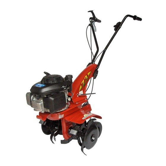
    Levier marche arrière - 4.Epéron pour régler le fraisage (position unique). - 5. Fraises (avec éléments de rallonge). - 6. Poignée de serrage mancheron /châssis - 7. Mancheron – 8. Roue de transport – 9. Carter de la fraise - 10. Poignée de démarrage du moteur (auto enrouleur) – 11.Moteur – 12. Levier blocage/déblocage guidon –...
  • Page 25 PROBLEME Veillez à débrancher le capuchon de la bougie avant tout nettoyage et entretien ! Problème Solution Le moteur ne démarre pas Le carburant est épuisé, faites le plein. Vérifier si l’accélérateur est positionné sur START. Vérifier si le capuchon de la bougie est bien inséré. Vérifier l’état de la bougie et éventuellement la remplaçer.
  • Page 26 Übersetzung der originalen Betriebsanleitung Einleitung Schwere Gefahr für die Unversehrtheit des Bedieners und der Personen in der Reichweite der Maschine. Verehrter Kunde, Sie haben ein neues Gerät erworben. Wir bedanken uns für Ihr Vertrauen, das Sie in unsere Qualitätsprodukte setzen und wünschen Ihnen viel Freude beim Arbeiten mit Ihrem neuen Gerät.
  • Page 27: Montage Der Motorhacke

    8 - Die Maschine nicht in geschlossenen Räumen laufen lassen, wo die entstehenden Abgase sich anhäufen könnten. 9 - HINWEIS Benzin ist ein feuergefährlicher Stoff: Nicht in geschlossenen Räumen und nicht bei laufendem Motor tanken, nicht rauchen und auf den aus dem Tank auslaufenden Treibstoff achten. Bei auslaufendem Treibstoff nicht versuchen, den Motor zu starten, sondern die Maschine von der betroffenen Stelle entfernen und vermeiden, Zündquellen zu erzeugen, bis die Benzindämpfe nicht abgezogen sind.
  • Page 28 (5) montieren wie in der Abbildung gezeigt. Für die Montage der Lenkstange (6) an der Lenkstangenhalterung (1) wie folgt vorgehen: Im oberen Loch die Schraube (7) in die Kabeldurchführung (8) einführen, in dessen Inneren sich bereits die Kabel befinden, und dann mit der Mutter (9) sichern.
  • Page 29 BETRIEBSANLEITUNGEN Nach der Montage und der Ausführung der Einstellungen ist die Motorhacke bereit, seine Arbeit aufzunehmen. Den Lenkholm auf die Höhe stellen, die am besten zu der auszuführenden Arbeit passt. (Abb. 10) Vor dem Starten des Motors immer sicherstellen, dass die Motorhacke einen einwandfreien Betriebszustand aufweist.
  • Page 30: Technische Daten

    BESCHREIBUNG DER BEDIENUNGSELEMENTE (Abb. 14) 1. Gashebel - 2. Hackgang-Schaltenhebel (Unfallschutzvorrichtung). - 3. Bedienungshebel für Rückwärts-Antrieb - 4. Bremssporn zur Frästiefe-Einstellung (eine Position). - 5. Hackmesser (mit Verbreiterung). - 6. Flügelmutter-Handgriff für Holmverriegelung - 7. Bedienungshebel für Rückwärts-Antrieb – 8. Transportrad – 9 Schutzabdeckung – 10 Startseil für Motor –...
  • Page 31 STÖRUNG Vor allen Wartungs- und Reinigungsarbeiten Zündkerzenstecker abziehen! Störung Beseitigung Motor springt nicht an Benzin auftanken. Gashebel auf Position “START” stellen. Zündkerzenstecker auf die Zündkerze aufstecken. Zündkerze überprüfen, eventuell erneuern. Kraftstoffhahn aufdrehen (nur für Motoren mit Kraftstoffhahn). Motorleistung lässt nach Luftfilter reinigen.
  • Page 32: Normas De Seguridad

    Traducción del manual de instrucciones original INTRODUCCIÓN Peligro grave para la incolumidad del operador y de las personas expuestas. Estimado cliente, usted ha comprado un nuevo equipo. Le agradecemos la confianza otorgada a nuestros productos y le deseamos un agradable uso de su máquina. Hemos creado estas instrucciones de uso para asegurarle, desde el principio, un funcionamiento sin inconvenientes.
  • Page 33 7) Aléjese de la máquina después de apagar el motor. 8) No encienda la máquina en locales cerrados, donde se puedan acumular los humos con monóxido de carbono. 9) ADVERTENCIA: la gasolina es muy inflamable, conserve el carburante en recipientes adecuados. No recargue gasolina en locales cerrados ni con el motor en marcha.
  • Page 34 MONTAJE SOPORTE DEL MANILLAR Y MANILLAR (Fig. 4) Monte el soporte del manillar (1) en la motoazada usando cuatro tornillos (2) ya situados en la placa, arandelas (3) y tuercas (4). Monte el pasacables (5) como se indica en la figura. Para montar el manillar (6) en el soporte del manillar (1), realice el siguiente proceso: en el orificio superior introduzca el tornillo (7) en el pasacables (8), en el interior del cual ya se encuentran introducidos los cables.
  • Page 35 REGULACIÓN DE LA ALTURA (Fig. 10B): para desbloquear el manillar (2) es necesario rotar los pomos (4) para aflojarlos. Suba o baje el manillar hasta la posición deseada (regulación estándar a la altura de la cadera) y, elegida la posición exacta, bloquee los dos pomos. INSTRUCCIONES DE USO Tras las operaciones de montaje y regulación, la motoazada está...
  • Page 36: Ruido Aéreo Y Vibraciones

    interior de un edificio, donde los vapores puedan alcanzar una llama libre o una chispa. Para reducir el peligro de incendio, mantenga el motor, el silenciador y la zona de almacenamiento de la gasolina libre de hojas, hierba y exceso de grasa. DESCRIPCIÓN DE LOS MANDOS (Fig.
  • Page 37 AVERÍAS Antes de ejecutar cualquier trabajo de mantenimiento o limpieza, desconectar el enchufe de la bujía. Avería Arreglo El motor no arranca El carburante ha terminado - repostar carburante. Comprobar que la palanca del mando acelerador esté en la posición “start”. Comprobar que le enchufe de la bujía esté...
  • Page 38: Normas De Segurança

    Tradução do manual original INTRODUÇÃO Perigo grave para a segurança do operador e das pessoas expostas. Caro cliente, um novo equipamento foi adquirido. Agradecemos a confiança que deu aos nossos produtos e desejamos-lhe uma agradável utilização da sua máquina. Elaboramos estas instruções de utilização com o objetivo de assegurar, desde o momento inicial, um funcionamento sem problemas. Siga atentamente estes conselhos: terá...
  • Page 39: Montagem Da Motoenxada

    para a prevenção de acidentes e calças compridas. Prestar atenção pois a fresa em movimento é potencialmente perigosa para mãos e pés. É importante caminhar e não correr durante o trabalho. 6) O motor deve estar desligado durante o transporte da máquina e todas as operações de manutenção, limpeza e troca de acessórios. 7) Afastar-se da máquina somente depois de desligar o motor.
  • Page 40 lo girando o puxador (2). A roda de transferência (Fig.3 part.1) serve somente para o transporte da motoenxada. Deve ser montada depois de girar o esporão a 180°, bloqueando-o com parafuso e aleta (2). A roda deve ser retirada durante a fase de trabalho: soltar o parafuso com aleta e retirar o esporão, reposicionando-o girado como indicado na Fig.
  • Page 41 antes de iniciar qualquer tipo de trabalho, regular o guiador conforme as exigências. REGULAÇÃO LATERAL (Fig. 10A): a orientação lateral do guiador permite que o operador não pise no terreno já sachado e não danifique a vegetação. Continuar levantando a alavanca (3) para desbloquear o guiador (2) do suporte (1). Rodar o guiador (2) para a parte desejada e abaixar a alavanca (3) para bloqueá-lo.
  • Page 42 ARMAZENAMENTO E MANUTENÇÃO PERIÓDICA ( Fig.15) Manter apertadas todas as porcas e os parafusos, de modo a garantir o funcionamento da máquina em condições de segurança. Controlar periodicamente o aperto do guiador (1) no suporte (2). Caso o aperto não esteja garantido, abaixar a alavanca (3) e apertar a porca (4).
  • Page 43 FALHAS Antes de realizar qualquer operação, remover a cobertura da vela! Falha Solução O motor não arranca Combustível esgotado, reabastecer. Controlar se o acelerador esteja posicionado no START. Controlar se a cobertura da vela está bem inserida. Controlar o estado da vela e eventualmente substituir. Controlar se a torneira do combustível está...
  • Page 44 07/2020 cod. 37.3065.000...

Table des Matières