
Manuels Connexes pour geo-FENNEL FET 220


Sommaire des Matières pour geo-FENNEL FET 220
- Page 1 DE | EN | FR FET 220 BEDIENUNGSANLEITUNG USER MANUAL MODE D‘EMPLOI www.geo-fennel.de www.geo-fennel.com www.geo-fennel.fr...
-
Page 2: Lieferumfang
Sehr geehrter Kunde, vielen Dank für das Vertrauen, welches Sie uns beim Erwerb Ihres neuen geo-FENNEL-Gerätes ent- gegengebracht haben. Dieses hochwertige Qualitätsprodukt wurde mit größter Sorgfalt produziert und qualitätsgeprüft. Die beigefügte Anleitung wird Ihnen helfen, das Gerät sachgemäß zu bedienen. Bitte lesen Sie ins- besondere auch die Sicherheitshinweise vor der Inbetriebnahme aufmerksam durch. - Page 3 Technische Daten Fernrohr: Vergrößerung 30-fach Objektivdurchmesser 45 mm Kürzeste Zielweite 1,5 m Winkelmessung: absoluter Encoder Genauigkeit 6 mgon (20“) Kleinster Messwert 3 mgon (10“) Messeinheiten 400 gon / 360° Display / Beleuchtung 1 x LCD / ja Libellen: Röhrenlibelle 30“ / 2 mm Dosenlibelle 8“...
-
Page 4: Stromversorgung
STROMVERSORGUNG Gerät ausschalten und Batterie- / Akkufach abnehmen. Der Akku wird außerhalb des Gerätes mit dem Ladegerät aufgeladen und anschließend wieder an das Gehäuse angeklickt. Nur bei Batteriewechsel: Haken herunterdrücken und Deckel abnehmen. Neuen Satz Alkaline-Batterien einlegen. Deckel schließen und Batteriefach wieder an das Gehäuse anklicken. BATTERIEZUSTANDSANZEIGE Voll geladen Ausreichend geladen... -
Page 5: Bedienfeld Und Display
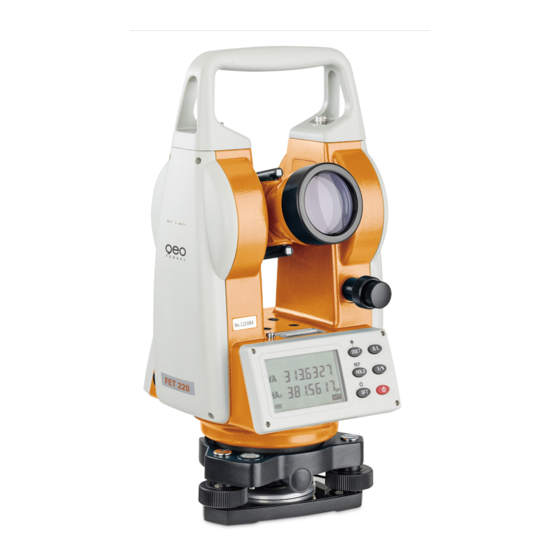
BEDIENFELD UND DISPLAY 1. Handgriff 2. Schraube Handgriff 3. Grobvisier 4. Vertikalklemme und Vertikalfeintrieb 5. Bedientastatur 6. Objektiv 7 . Röhrenlibelle 8. Display 9. Fernrohrokular 10. Dreifuß 11. Fußschraube 12. Fokussierung 13. Batterie- / Akkufach 14. Horizontalklemme und Horizontalfeintrieb 15. Verriegelungshebel... -
Page 6: Displayanzeige
DISPLAYANZEIGE Vertikalwinkel Horizontalwinkel, Zählrichtung rechtsläufig Horizontalwinkel, Zählrichtung linksläufig Umschalttaste Repetitionsweise Winkelmessung Automatische Abschaltung HOLD Feststellung der Hz-Kreisablesung Prozent Entfernungseinheit Winkeleinheit Akku-/Batteriezustandsanzeige BEDIENFELD Taste Funktion 1 Funktion 2 0SET Nullsetzung Horizontalwinkel Laserlot HOLD Feststellung der Hz-Kreisablesung Wiederholung horizontale Winkelmes- sung Umschalttaste für 2. Funktion Displaybeleuchtung Ein/Aus Auswahl der Zählrichtung des Horizontal- kreiswinkels... -
Page 7: Bedienung
BEDIENUNG VORBEREITUNG ZUR MESSUNG Stativ Stativbeine auf gewünschte Höhe ausziehen und festklemmen. Stativ sicher aufstellen. Instrument auf Stativ befestigen. Instrument vorsichtig auf das Stativ setzen. Die Stativanzugsschraube (mit 5/8“-Gewinde) einschrauben, bis das Instrument sicher befestigt ist. Libellen einspielen Zunächst die Dosenlibelle und anschließend die Röhrenlibelle einspielen. Die Röhrenlibelle nachstellen, bis sie bei Drehung des Theodolit-Oberteils in allen Lagen den Umschlag hält. - Page 8 ELEKTRONISCHE V-KREIS-ANLGEICHUNG · Tasten „Ein/Aus“ und „R/L “ zusammen drücken. · Anzeige „F1“ . · Taste „0-SET“ drücken. · Anzeige „F1“erste Lage (A). · Abgleich über Kollimator mit „0-SET“ bestätigen. · Durchschlagen. · Anzeige „F2“ zweite Lage (B). · Abgleich über Kollimator mit „0-SET“ bestätigen. UMSCHALTUNG ZÄHLRICHTUNG DES HORIZONTALKREISES HA / HA Im Standardmodus ist die Zählrichtung des Horizontalwinkels rechtsläufig (Displayanzeige HA...
-
Page 9: Distanzmessung Mit Dem Fadenkreuz
DISTANZMESSUNG MIT DEM FADENKREUZ Mit dem FET 220 können in Verbindung mit einer Teleskop-Nivellierlatte manuell Entfernungen gemes- sen werden. · Nivellierlatte auf Zielpunkt stellen. · Mit dem Fernrohr des Gerätes die Nivellierlatte anvisieren. · Den Wert des Abschnitts „d“ zwischen den beiden kleinen horizontalen Distanzfäden mit... -
Page 10: Parameter Setzen
PARAMETER SETZEN · Tasten „Ein/Aus“ und „0Set“ gleichzeitig drücken. · Um die gewünschten Ziffern (1-4) anzuwählen, Tasten „0SET“ oder „HOLD“ drücken. · Um den Parameter umzustellen, die Taste „R/L “ oder „V/%“ drücken. · Um das Menü zu verlassen, „SFT“ drücken. ·... -
Page 11: Sicherheitshinweise
SICHERHEITSHINWEISE BESTIMMUNGSGEMÄSSE VERWENDUNG Triangulierungen, Polygonierungen und Ingenieurvermessungen im Bauwesen sowie Katastervermes- sung. UMGANG UND PFLEGE Messinstrumente generell sorgsam behandeln. Nach Benutzung mit weichem Tuch reinigen (ggfs. Tuch in etwas Wasser tränken). Wenn das Gerät feucht war, sorgsam trocknen. Erst in den Koffer oder die Tasche packen, wenn es absolut trocken ist. -
Page 12: Warn- Und Sicherheitshinweise
Das Gerät darf ohne weitere Sicherheitsmaßnahmen eingesetzt werden. Das Auge ist bei zufälligem, kurzzeitigem Hineinsehen in den Laserstrahl durch den Lidschlussreflex geschützt. Laserwarnschilder der Klasse 2 sind gut sichtbar am Gerät angebracht. www.geo-fennel.de G ERMAN Y Laser IEC 60825-1:2014 P ≤ 1 mW @ 635 - 670 nm... - Page 14 Dear customer, Thank you for your confidence in us having purchased a geo-FENNEL instrument. This manual will help you to operate the instrument appropriately. Please read the manual carefully - particularly the safety instructions. A proper use only guarantees a longtime and reliable operation.
-
Page 15: Technical Data
Technical data Telescope: Magnification 30 x Clear objective aperture 45 mm Shortest focussing distance 1,5 m Angle measurement: Absolute encoder Accuracy 6 mgon (20“) Shortest focussing distance 3 mgon (10“) Measuring units 400 gon / 360° Display illumination 1 x LCD / yes Vials: Circular level 30“... -
Page 16: Battery Status Indication
POWER SUPPY Power off the instrument and remove the battery case. Press down the hook of the battery box and remove the cover. Charge the battery outside of the instrument and insert it again when fully charged. Alternatively: Insert new alkaline batteries. Close the cover and insert the battery box again. -
Page 17: Keypad And Functions
KEYPAD AND FUNCTIONS 1. Carrying handle 2. Handle locking screw 3. Optical sight 4. Vertical tangent screw and clamp 5. Keypad 6. Objective lens 7 . Plate level 8. Display 9. Eyepiece 10. Tribrach 11. Footscrew 12. Focusing drive 13. Battery compartment 14. -
Page 18: Display Indication
DISPLAY INDICATION Vertical angle Horizontal angle right Horizontal angle left Select the second function Repeat the horizontal angle Power on/off HOLD Hold the horizontal angle Vertical grade percentage Distance unit Angle unit Battery status indication KEYPAD FUNCTIONS Button Function 1 Function 2 0SET Horizontal angle “0 Set”... -
Page 19: Preparation For Measurement
OPERATION PREPARATION FOR MEASUREMENT Level and centre the instrument precisely to ensure an optimum performance. Setting up the instrument and the tripod Extend the tripod legs to a suitable height and tighten the locking screw. Attach the instrument onto the tripod carefully. With the tripod centring screw slightly loose move the instrument across the tripod head until the laser plummet is in coincidence with the ground point. - Page 20 VERTICAL ANGLE SET · Press the power button and “R/L “ simultaneously. “F1” will be displayed. · Press the „O-SET“ button. Indication: „F1“ - first rotation (A). · Confirm the adjustment via collimator with „O-SET“ . · Rotate. · „F2“ will be displayed - second rotation (B). ·...
-
Page 21: Display Illumination
DISTANCE MEASUREMENT USING THE STADIA METHOD A distance measurement can be carried out yb using the crosshair. · Read the levelling rod. · Aim the instrument‘s telescope at the levelling rod. · Multiply the value of the distance „d“ between the two stadia hairs with 100. ·... -
Page 22: Function Setting Method
FUNCTION SETTING METHOD · Power on and press 0SET“ simultaneously to enter the function setting mode. · Press “0SET“ or “HOLD“ to select the items (1 - 4). · Press “R/L “ or “V%“ to change the setting of the selected item. ·... -
Page 23: Safety Notes
SAFETY NOTES INTENDED USE OF INSTRUMENT Triangle, polygon and engineer measurements in the field of civil engineering as well as cadastral survey. CARE AND CLEANING Handle measuring instruments with care. Clean with soft cloth only after any use. If necessary damp the cloth with some water. -
Page 24: Safety Instructions
It is allowed to use the unit without further safety precautions. The eye protection is normally secured by the aversion responses and the blink reflex. The laser instrument is marked with class 2 warning labels. www.geo-fennel.de G ERMAN Y Laser IEC 60825-1:2014 P ≤... -
Page 26: Livré Comme Suit
Contenu 1. Livré comme suit 2. Alimentation en courant 3. Clavier et écran 4. Opération 5. Consignes de sécurité LIVRÉ COMME SUIT · Théodolite électronique FET 220 · Embase · Batterie NiMH · Chargeur · Bloc de piles en secours ·... - Page 27 Données techniques Télescope: Grossissement 30 x Ouverture de l‘objectif 45 mm Visée minimale de focalisation 1,5 m Mesure d‘angle: Encodeur absolu Précision 6 mgon (20“) Visée minimale de focalisation 3 mgon (10“) Unités de mesure 400 gon / 360° Écran / rétro éclairage 1 x LCD / oui Nivelles: Nivelle circulaire...
-
Page 28: Alimentation En Courant
ALIMENTATION EN COURANT Appuyer de haut en bas sur le clip et enlevez les piles. En cas d‘utilisation de piles alcalines: Appuyez sur le bouton vers le bas pour retirer le compartiment des piles. Remplacement des piles: Poussez le crochet vers le bas pour retirer le capot du compartiment des piles. Remplacez les anciennes piles alcalines par de nouvelles / charger la batterie rechargeable - à... -
Page 29: Clavier Et Écran
CLAVIER ET ÉCRAN 1. Poignée 2. Vis de fixation de la poignée 3. Viseur optique 4. Vis de réglage micrométrique verticale et de blocage de mouvement 5. Bouton d‘exploitation 6. Lentille de l‘objectif 7 . Nivelle principale 8. Écran 9. Oculaire 10. -
Page 30: Affichage
AFFICHAGE Angle vertical Angle horizontal droit Angle horizontal gauche La deuxième fonction Mode répétition Arrêt automatique HOLD Mémorisation de l‘angle horizontal Pourcentage de pente Unité de distance Unité d‘angle Niveau de la batterie CLAVIER Bouton Fonction 1 Fonction 2 0SET Réglez l‘angle horizontal 0 Allumer ou éteindre le plomb laser HOLD... -
Page 31: Mise En Station Du Théodolite
OPÉRATION MISE EN STATION DU THÉODOLITE Centrer et mettre l‘instrument de niveau pour s‘assurer de ses bonnes performances. Montez le trépied Tout d‘abord placer les jambes du trépied à un endroit approprié et serrer le dispositif de verrouillage. Montez l‘ instrument sur le trépied. Fixez l‘appareil sur le trépied avec soin, puis bougez l‘instrument en desserrant la vis de blocage centrale. - Page 32 ANGLE VERTICAL · Allumer l‘appareil tout en appuyant sur „R / L “ , „SETUP“ s‘affiche. · Ensuite, la première ligne affiche „SET F1“ et clignote. · Mettre l‘instrument de niveau et viser la cible de référence à l‘aide du télescope (Fig 1), appuyez sur „0SET“...
-
Page 33: Parametres De Configuration
MESURE DE DISTANCE La mesure de la distance avec la croix est une autre application du FET 220. Pour exécuter cette fonc- tion, une canne dont on connaît l‘échelle est nécessaire. En regardant à travers le télescope, la longueur entre les lignes stadia du haut et du bas doit être multipliée par 100. C‘est la distance entre le centre de l‘instrument et la canne. -
Page 34: Méthode De Configuration
MÉTHODE DE CONFIGURATION · Allumer l‘appareil tout en appuyant sur „0SET“ pour entrer dans le mode de réglage de fonction. · Appuyez sur „0SET“ ou „HOLD“ pour sélectionner l‘élément (1 - 4). · Appuyez sur „R/L» ou „V%“ pour modifier le réglage de l‘élément sélectionné. ·... -
Page 35: Consignes De Sécurité
CONSIGNES DE SÉCURITÉ UTILISATION CONFORME AUX PRESCRIPTIONS Trianguler, polygoner et mesurages d‘ingénieur dans le secteur de la construction et cadastre. NETTOYAGE / REMISAGE (à l‘état humide) Essuyer l’instrument mouillé, humide ou sali en le frottant uniquement avec un tissu de nettoyage. Quant à... -
Page 36: Exclusion De La Responsabilité
EXCLUSION DE LA RESPONSABILITÉ 1. L ‘utilisateur de ce produit est tenu de respecter ponctuellement les instructions du mode d‘emploi. Tous les instruments ont été très soigneusement vérifiés avant leur livraison. Toutefois, l‘utilisateur devra s‘assurer de la précision de ce niveau avant chaque emploi. 2. -
Page 37: Classification Des Lasers
Les pictogrammes de danger de la classe 2 sont bien visibles sur le niveau. www.geo-fennel.de G ERMAN Y Laser IEC 60825-1:2014 P ≤... - Page 40 GmbH Technische Änderungen vorbehalten. Kupferstraße 6 All instruments subject to technical changes. D-34225 Baunatal Sous réserve de modifications techniques. Tel. +49 561 / 49 21 45 +49 561 / 49 72 34 info@geo-fennel.de 06/2016 www.geo-fennel.de Precision by tradition.