Siemens SIMOVERT MASTERDRIVES Motion Control Instructions De Service

Siemens SIMOVERT MASTERDRIVES Motion Control Instructions De Service

Masquer les pouces Voir aussi pour SIMOVERT MASTERDRIVES Motion Control:
Table des Matières

Publicité

Les langues disponibles

Les langues disponibles

Liens rapides

Instructions de service / Operating Instructions
Edition: AH
simovert
masterdrives
Motion Control
Convertisseur indirect (AC-AC), forme Compact PLUS
Frequency Converter (AC-AC) Compact PLUS Type

Publicité

Chapitres

Table des Matières
loading

Sommaire des Matières pour Siemens SIMOVERT MASTERDRIVES Motion Control

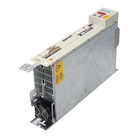
  • Page 1 Instructions de service / Operating Instructions Edition: AH simovert masterdrives Motion Control Convertisseur indirect (AC-AC), forme Compact PLUS Frequency Converter (AC-AC) Compact PLUS Type...
  • Page 3: Table Des Matières

    Connexions de commande ................7-12 Sections des conducteurs, fusibles, inductances........... 7-22 Combinaisons d'appareils................7-23 PARAMETRAGE....................8-1 Menus de paramètres..................8-1 Entrée des paramètres depuis le PMU............. 8-5 Entrée des paramètres depuis l'OP1S ............. 8-8 Siemens AG 6SE7087-7JP50 SIMOVERT MASTERDRIVES Instructions de service...
  • Page 4 Remplacement du ventilateur sur les boîtiers de largeur 180 mm....9-3 FORMATION ....................10-1 CARACTERISTIQUES TECHNIQUES ............11-1 DEFAUTS ET ALARMES ................12-1 12.1 Défauts......................12-1 12.2 Alarmes......................12-14 12.3 Erreurs fatales (FF)..................12-38 COMPATIBILITE ENVIRONNEMENTALE............ 13-1 6SE7087-7JP50 Siemens AG Instructions de service SIMOVERT MASTERDRIVES...
  • Page 5: Definitions Et Avertissements

    à un résultat ou à un état non souhaité. NOTA Au sens de la présente documentation, la mention "NOTA" met en valeur une information importante relative au produit ou à la partie de la documentation traitée. Siemens AG 6SE7087-7JP50 SIMOVERT MASTERDRIVES Instructions de service...
  • Page 6 étendre, ni restreindre les clauses de garantie contractuelles. Utilisation des produits Siemens conforme à leur destination ATTENTION Les produits Siemens ne doivent être utilisés que pour les cas d'application prévus dans le catalogue et dans la documentation technique correspondante. S'ils sont utilisés en liaison avec des produits et composants d'autres marques, ceux-ci doivent être...
  • Page 7 ♦ d = blouse antistatique ♦ e = bracelet antistatique ♦ f = raccordement à la terre de l'armoire Position assise Position debout Position alternée assise/debout Fig. 1-1 Mesures de protection contre les décharges électrostatiques Siemens AG 6SE7087-7JP50 SIMOVERT MASTERDRIVES Instructions de service...
  • Page 8: Consignes De Sécurité Et D'emploi Relatives Aux Variateurs De Vitesse

    être respectées. 7. Entretien et maintenance Les conditions climatiques selon la EN 50178 doivent La documentation du constructeur doit être prise en consi- être respectées. dération. CONSERVER CES INSTRUCTIONS DE SECURITE ! 6SE7087-7JP50 Siemens AG Instructions de service SIMOVERT MASTERDRIVES...
  • Page 9: Risques Résiduels De Power Drive Systems (Pds)

    Pour plus d'informations sur les risques résiduels en rapport avec les composants du PDS, veuillez vous reporter aux chapitres afférents de la documentation technique de l'utilisateur. Siemens AG 6SE7087-7JP50 SIMOVERT MASTERDRIVES Instructions de service...
  • Page 10 Il convient aussi de respecter les consignes de sécurité afférentes figurant dans les chapitres Entreposage, Transport et manutention, Montage, Mise en service, Exploitation, Maintenance, Démantèlement et élimination en fin de vie. 6SE7087-7JP50 Siemens AG Instructions de service SIMOVERT MASTERDRIVES...
  • Page 11: Description

    U2/T1 V1/L2 V2/T2 Départ moteur W1/L3 W2/T3 Redresseur Précharge Circuit Onduleur interm. C / L+ Résistance D / L - de freinage Hacheur freinage Fig. 2-1 Schéma de principe du convertisseur indirect Siemens AG 6SE7087-7JP50 SIMOVERT MASTERDRIVES Instructions de service...
  • Page 13: Transport, Entreposage, Deballage

    éliminé en se conformant aux prescriptions locales pour les cartonnages. Après déballage, contrôle de complétude de l'envoi, vérification de l'état intact de l'appareil et de ses constituants, on peut entreprendre le montage et la mise en service. Siemens AG 6SE7087-7JP50 SIMOVERT MASTERDRIVES Instructions de service...
  • Page 15: Premiere Mise En Service

    24 V ou l'électronique, l'appareil procède à son initialisation. la tension réseau Cette opération peut durer quelques secondes. Suite à quoi, l'état de l'appareil est signalé sur l'afficheur du PMU. Siemens AG 6SE7087-7JP50 SIMOVERT MASTERDRIVES Instructions de service...
  • Page 16 Il est recommandé de n'accoupler la machine opératrice que si le test fonctionnel a donné satisfaction. Poursuite de la mise en service et du paramétrage en fonction du cas d'application concret siehe "Ans 6SE7087-7JP50 Siemens AG Instructions de service SIMOVERT MASTERDRIVES...
  • Page 17: Montage

    éléments qui sont susceptibles d'entraver la circulation de l'air de refroidissement. Lors de l'implantation en armoire, la ventilation de l'armoire doit être conçue en fonction de la puissance dissipée. Vous trouverez les indications correspondantes aux caractéristiques techniques. Siemens AG 6SE7087-7JP50 SIMOVERT MASTERDRIVES Instructions de service...
  • Page 18 Si la température de l'air de refroidissement dépasse 45 °C (113 °F), et si l'altitude d'installation est supérieure à 1000 m, il faudra réduire la puissance. Surface de fixation Air de refroi- dissement Fig. 5-1 Distance minimale pour le refroidissement 6SE7087-7JP50 Siemens AG Instructions de service SIMOVERT MASTERDRIVES...
  • Page 19: Vue De Côté

    22,5 mm 135 mm 180 mm 220 mm 5,5 / 7,5 kW 11 / 15 kW Vue de côté Vue de face Fig. 5-3 Encombrement, boîtiers de largeur 135 mm et 180 mm Siemens AG 6SE7087-7JP50 SIMOVERT MASTERDRIVES Instructions de service...
  • Page 20: Montage Des Cartes Optionnelles

    ♦ Retirez de la face avant l'obturateur de l'emplacement voulu. Retirer l'obturateur d'emplacement ♦ Pour ce faire, il faut trancher avec précaution au moyen d'un couteau à lame mince les quatre points de liaison entre l'obturateur et la face avant. 6SE7087-7JP50 Siemens AG Instructions de service SIMOVERT MASTERDRIVES...
  • Page 21 Etiquettes de repérage des cartes optionnelles Vis de fixation du panneau latéral Fig. 5-4 Disposition des vis de fixation du panneau latéral de droite Fig. 5-5 Dépose du panneau latéral de droite Siemens AG 6SE7087-7JP50 SIMOVERT MASTERDRIVES Instructions de service...
  • Page 22 Placez le fixe-cartes dans le sens de la longueur sur l'arête arrière des pour cartes cartes optionnelles installées et vissez les vis, qui avaient été retirés au optionnelles préalable, sur les points de fixation. 6SE7087-7JP50 Siemens AG Instructions de service SIMOVERT MASTERDRIVES...
  • Page 23 à l'emplacement prévu sur la face avant de l'appareil. ♦ Après la remise sous tension, vous pouvez enregistrer les cartes optionnelles dans le logiciel de l'appareil et entamer la mise en service. Siemens AG 6SE7087-7JP50 SIMOVERT MASTERDRIVES Instructions de service...
  • Page 24: Montage Des Cartes Optionnelles Pour Boîtiers De Largeur 135 Mm Et 180 Mm

    Si le convertisseur est utilisé en tant que variateur monoaxe, les barres du circuit intermédiaire ne sont pas présentes. Vous pouvez alors déposer le convertisseur immédiatement après avoir défait les vis de fixation. Fig. 5-7 6SE7087-7JP50 Siemens AG Instructions de service SIMOVERT MASTERDRIVES...
  • Page 25 (voir détail A, Fig. 5-8). Il suffit de libérer le plastron frontal de la paroi de droite. La face avant et de gauche forment une unité. Fig. 5-8 Siemens AG 6SE7087-7JP50 SIMOVERT MASTERDRIVES Instructions de service...
  • Page 26 ♦ Retirez les vis de fixation du fixe-cartes des plots et sortez le fixe- Démonter le fixe- cartes pour cartes cartes de l'appareil. optionnelles 6SE7087-7JP50 Siemens AG 5-10 Instructions de service SIMOVERT MASTERDRIVES...
  • Page 27 Placez le fixe-cartes dans le sens de la longueur sur l'arête arrière des pour cartes cartes optionnelles installées et vissez les vis, qui avaient été retirés au optionnelles préalable, sur les points de fixation. Siemens AG 6SE7087-7JP50 5-11 SIMOVERT MASTERDRIVES Instructions de service...
  • Page 28 à l'emplacement prévu sur la face avant de l'appareil. ♦ Après la remise sous tension, vous pouvez enregistrer les cartes optionnelles dans le logiciel de l'appareil et entamer la mise en service. 6SE7087-7JP50 Siemens AG 5-12 Instructions de service SIMOVERT MASTERDRIVES...
  • Page 29: Installation Dans Les Regles De La Cem

    SIMOVERT MASTERDRIVES. Il faut que le blindage ne soit pas interrompu, par exemple par un bornier intermédiaire. Utiliser de préférence des câbles confectionnés, équipés de blindages multiples, pour raccorder les codeurs ou les résolveurs. (voir catalogue DA65). Siemens AG 6SE7087-7JP50 SIMOVERT MASTERDRIVES Instructions de service...
  • Page 30 SIMOVERT MASTERDRIVES. Le montage d'un filtre réseau supplémentaire dépend de l'automate utilisé et de la réalisation du câblage dans le reste de l'armoire. 6SE7087-7JP50 Siemens AG Instructions de service SIMOVERT MASTERDRIVES...
  • Page 31 Les câbles seront aussi blindés sur leur trajet à l’intérieur de l’armoire ; ou du moins être écranés à l'aide de tôles de séparation mises à la terre. Utiliser des câbles appropriés, par ex. Siemens PROTOFLEX-EMV-CY (4 × 1,5 mm ... 4 × 120 mm ²...
  • Page 32 Fig. 6-1 Exemples d’application des règles de base de la CEM Fig. 6-2 Mise à la terre du blindage du câble de liaison vers le moteur à son entrée dans l’armoire 6SE7087-7JP50 Siemens AG Instructions de service SIMOVERT MASTERDRIVES...
  • Page 33 La boîte à bornes du moteur ne doit pas être en matière plastique ! Collier pour blin- dage Bride "Rilsan" de fixation Fig. 6-4 Mise à la terre des câbles de signaux sur convertisseur SIMOVERT MASTERDRIVES Siemens AG 6SE7087-7JP50 SIMOVERT MASTERDRIVES Instructions de service...
  • Page 34 (bon contact électrique) Fig. 6-5 Mise à la terre des câbles de signaux dans l’armoire On évitera dans la mesure du possible les borniers intermédiaires, car il diminuent l’efficacité du blindage ! 6SE7087-7JP50 Siemens AG Instructions de service SIMOVERT MASTERDRIVES...
  • Page 35: Raccordement

    ♦ sensibilité du dispositif de protection différentiel ≥ 300 mA ♦ câbles moteur courts (l < 20 m) ♦ pas de filtre d'antiparasitage ♦ un seul convertisseur en aval du dispositif de protection différentiel Siemens AG 6SE7087-7JP50 SIMOVERT MASTERDRIVES Instructions de service...
  • Page 36 RS232 / RS485 (USS) X103 Empl. C Bornier moteur X2 Tôle pour blindage Tôle pour blindage du câble moteur des câbles de cde Fig. 7-1 Connectique, boîtiers de largeur jusqu'à 90 mm 6SE7087-7JP50 Siemens AG Instructions de service SIMOVERT MASTERDRIVES...
  • Page 37 RS485 (USS) X100 Résistance de terminaison de bus (USS) S1 Empl. A X101 Bornier X101 Empl. B X103 RS232/RS485 (USS) X103 Empl. C Bornier moteur X2 Fig. 7-2 Connectique, boîtiers de largeur 135 mm Siemens AG 6SE7087-7JP50 SIMOVERT MASTERDRIVES Instructions de service...
  • Page 38 RS485 (USS) X100 Résistance de terminaison de bus (USS) S1 Empl. A X101 Bornier X101 Empl. B X103 Empl. C RS232/RS485 (USS) X103 Bornier moteur X2 Fig. 7-3 Connectique, boîtiers de largeur 180 mm 6SE7087-7JP50 Siemens AG Instructions de service SIMOVERT MASTERDRIVES...
  • Page 39: Connexions De Puissance

    A l'état monté, la borne U1 se trouve à l'avant. Tableau 7-1 Bornier réseau AVERTISSEMENT Le connecteur sera fixé par vis au boîtier (tenue aux vibrations et protection contre le débranchement intempestif). Siemens AG 6SE7087-7JP50 SIMOVERT MASTERDRIVES Instructions de service...
  • Page 40 VDE 298 partie 2. Après la fixation du bornier, le blindage du câble de raccordement du moteur doit être connecté par une grande surface de contact à la tôle de connexion du blindage. 6SE7087-7JP50 Siemens AG Instructions de service SIMOVERT MASTERDRIVES...
  • Page 41 ♦ Pour des raisons de protection, les conducteurs raccordés au bornier X6 doivent avoir une section Cu de 4 mm IMPORTANT Longueur du câble entre le convertisseur et la résistance de freinage externe < 15 m. Siemens AG 6SE7087-7JP50 SIMOVERT MASTERDRIVES Instructions de service...
  • Page 42: Connexions De Puissance Pour Boîtiers De Largeur 135 Mm

    VDE 298 partie 2. Après la fixation du bornier, le blindage du câble de raccordement du moteur doit être connecté par une grande surface de contact à la tôle de connexion du blindage. 6SE7087-7JP50 Siemens AG Instructions de service SIMOVERT MASTERDRIVES...
  • Page 43 ♦ Pour des raisons de protection, les conducteurs raccordés au bornier X6 doivent avoir une section Cu de 4 mm IMPORTANT Longueur du câble entre le convertisseur et la résistance de freinage externe < 15 m. Siemens AG 6SE7087-7JP50 SIMOVERT MASTERDRIVES Instructions de service...
  • Page 44: Connexions De Puissance Pour Boîtiers De Largeur 180 Mm

    VDE 298 partie 2. Après la fixation du bornier, le blindage du câble de raccordement du moteur doit être connecté par une grande surface de contact à la tôle de connexion du blindage. 6SE7087-7JP50 Siemens AG 7-10 Instructions de service SIMOVERT MASTERDRIVES...
  • Page 45 ♦ Au cours de la précharge, les bornes sont traversées par le courant de charge de tous les modules à condensateurs raccordés. ♦ Pour des raisons de protection, les conducteurs raccordés au bornier X7 doivent avoir une section Cu de 4 mm Siemens AG 6SE7087-7JP50 7-11 SIMOVERT MASTERDRIVES...
  • Page 46: Connexions De Commande

    (par ex. disjoncteur 6 A, caract. de déclenchement C; Siemens 5SX2 106-7). (Câblage, voir complément joint à l'unité d'alimentation ou au convertisseur indirect.)
  • Page 47 Entrée analog. Empl. A Empl. B Sortie analog. Empl. C Protection -F1 : disjoncteur 6 A, caractéristique de déclenchement C par ex. Siemens 5SX2 106-7 (voir fiche jointe) Fig. 7-4 Vue d'ensemble de la connectique standard Siemens AG 6SE7087-7JP50 7-13...
  • Page 48 RS485N (USS) Bus USS RS485 Section possible : 2,5 mm² (AWG 12) A l'état monté, la borne 33 se trouve en haut. Tableau 7-15 Sortie de tension 24 V, bus USS 6SE7087-7JP50 Siemens AG 7-14 Instructions de service SIMOVERT MASTERDRIVES...
  • Page 49 états indéfinis, à moins qu'un comportement défini ait été spécifié pour ce laps de temps (et soit réalisé au niveau matériel). Siemens AG 6SE7087-7JP50 7-15 SIMOVERT MASTERDRIVES...
  • Page 50 Alimentation auxiliaire 5 V +5 V, max. 200 mA RS232 TxD Données d'émission via RS232 RS232 RS485 N Données via interface RS485 RS485 M_RS232/485 Masse numérique (via self) Tableau 7-17 Interface série 6SE7087-7JP50 Siemens AG 7-16 Instructions de service SIMOVERT MASTERDRIVES...
  • Page 51 Siemens AG, ses succursales et ses participations (désignés dans la suite par Siemens) ne sont pas en mesure de garantir toutes les propriétés d'une installation complète ou d'une machine qui n'a pas été...
  • Page 52 A l'état monté, la borne 2 se trouve en haut à l'avant. X533: A l'état monté, la borne 1 se trouve en haut à l'avant (voir Fig. 7-1 à 7-3) Tableau 7-19 Affectation des bornes avec l'option K80 6SE7087-7JP50 Siemens AG 7-18 Instructions de service SIMOVERT MASTERDRIVES...
  • Page 53 24 V aux bornes X9:1/2 doit fournir au moins 22 V afin d'assurer l'attraction fiable du relais de sécurité (chute de tension interne). Bornier - X533 Alimentation optocoupleur / Siemens AG 6SE7087-7JP50 7-19 SIMOVERT MASTERDRIVES Instructions de service...
  • Page 54 Fig. 7-5 Exemple d'utilisation de la fonction "Arrêt de sécurité" avec bloc logique de sécurité pour la surveillance d'un dispositif de protection mobile de la catégorie de sécurité 3 selon EN 954-1 6SE7087-7JP50 Siemens AG 7-20 Instructions de service SIMOVERT MASTERDRIVES...
  • Page 55 K1 par l'intermédiaire des contacts temporisés 47/48 après écoulement de la temporisation. Siemens AG 6SE7087-7JP50 7-21 SIMOVERT MASTERDRIVES...
  • Page 56: Sections Des Conducteurs, Fusibles, Inductances

    Tableau 7-20 pour l‘utilisation en entraînement monomoteur. NOTA Les fusibles à caractéristiques gR assurent en même temps la protection des lignes et des semi-conducteurs. 6SE7087-7JP50 Siemens AG 7-22 Instructions de service SIMOVERT MASTERDRIVES...
  • Page 57: Combinaisons D'appareils

    45 mm n'admet sur sa sortie 24 V qu'un seul onduleur additionnel. Pour assurer le maintien de la tension dans le circuit intermédiaire à courant continu, il est possible d'associer un convertisseur indirect de forme Compact PLUS (AC/AC) à un module à condensateurs. Siemens AG 6SE7087-7JP50 7-23 SIMOVERT MASTERDRIVES...
  • Page 59: Parametrage

    Il est possible qu'un paramètre appartienne à plusieurs menus. L'appartenance des paramètres aux différents menus est précisée dans la liste des paramètres. L'affectation s'effectue par l'intermédiaire des numéros attribués aux différents menus. Siemens AG 6SE7087-7JP50 SIMOVERT MASTERDRIVES Instructions de service...
  • Page 60 Synchronisme Blocs libres Positionnement Technologie Réglage/MDI L'accès aux menus sur fond grisé peut être protégé par inscription d'un mot de passe dans P359 P358 Clé P359 Serrure Fig. 8-1 Menus de paramètres 6SE7087-7JP50 Siemens AG Instructions de service SIMOVERT MASTERDRIVES...
  • Page 61 à la définition de la partie puissance (nécessaire puissance uniquement pour les appareils de forme Compact et encastrables) • la sélection de ce menu fait passer l'appareil dans l'état 0 "définition partie puissance" Tableau 8-1 Menus principaux Siemens AG 6SE7087-7JP50 SIMOVERT MASTERDRIVES Instructions de service...
  • Page 62 Vous utiliserez à cet effet les paramètres : ♦ P358 clé et ♦ P359 serrure. 6SE7087-7JP50 Siemens AG Instructions de service SIMOVERT MASTERDRIVES...
  • Page 63: Entrée Des Paramètres Depuis Le Pmu

    4 chiffres (le chiffre de droite clignote pour signaler la présence d'autres chiffres situés plus à droite) Tableau 8-2 Eléments de commande sur le PMU Siemens AG 6SE7087-7JP50 SIMOVERT MASTERDRIVES Instructions de service...
  • Page 64 Les modifications de paramètres effectuées au PMU sont toujours sauvegardées dans l'EEPROM après actionnement de la touche de commutation. 6SE7087-7JP50 Siemens AG Instructions de service SIMOVERT MASTERDRIVES...
  • Page 65 Sélectionner P060 P053 P060 Régler P060 sur 0002 et sélectionner le menu "Réglages fixes" P060 P060 Sélectionner P970 P060 P970 Régler P970 sur 0000 et lancer la réinitialisation des paramètres ∇ P970 °005 Siemens AG 6SE7087-7JP50 SIMOVERT MASTERDRIVES Instructions de service...
  • Page 66: Entrée Des Paramètres Depuis L'op1S

    Adaptateur pour montage sur porte d'armoire, 6SX7010-0AA00 5 m de câble inclus NOTA Les valeurs de réglage des paramètres pour les convertisseurs raccordés à l'OP1S figurent dans la documentation respective des convertisseurs (Compendium). 6SE7087-7JP50 Siemens AG Instructions de service SIMOVERT MASTERDRIVES...
  • Page 67 Dans une telle configuration, l'unité d'alimentation Compact Plus sert uniquement à la fixation mécanique de l'OP1S et à la transmission du bus aux onduleurs connectés en chaînage. L'unité d'alimentation n'a pas de fonction esclave. Siemens AG 6SE7087-7JP50 SIMOVERT MASTERDRIVES Instructions de service...
  • Page 68 (P). Les modifications de paramètres effectuées au moyen de l'OP1S sont toujours sauvegardées dans l'EEPROM après actionnement de la touche de commutation (P). 6SE7087-7JP50 Siemens AG 8-10 Instructions de service SIMOVERT MASTERDRIVES...
  • Page 69 *pas régl. usine Menu param.. busy.... Régl. fixes... Lancement réglage usine NOTA La réinitialisation des paramètres pour les repositionner sur le réglage usine ne peut pas être lancée à l'état "Fonctionnement". Siemens AG 6SE7087-7JP50 8-11 SIMOVERT MASTERDRIVES Instructions de service...
  • Page 70: Paramétrage Avec Drivemonitor

    DriveMonitor ne doit pas accéder via le connecteur Sub-D X300 si l'interface SST1 couplée en parallèle est utilisée à d'autres fins, par ex. pour la mise en réseau avec un SIMATIC comme maître. 6SE7087-7JP50 Siemens AG 8-12 Instructions de service SIMOVERT MASTERDRIVES...
  • Page 71: Etablissement De La Liaison Drivemonitor - Variateur

    8.4.2 Etablissement de la liaison DriveMonitor – variateur 8.4.2.1 Configuration de l'interface USS L'interface peut être configurée en passant par le menu Outils Paramètres ONLINE. Fig. 8-6 Paramètres ONLINE Siemens AG 6SE7087-7JP50 8-13 SIMOVERT MASTERDRIVES Instructions de service...
  • Page 72 Nombre de répétitions du contrat et délai de réponse ; en présence de défauts fréquents de communication, on peut améliorer la situation en augmentant les valeurs par défauts. Fig. 8-7 Configuration de l'interface 6SE7087-7JP50 Siemens AG 8-14 Instructions de service SIMOVERT MASTERDRIVES...
  • Page 73: Lancement De L'exploration Du Bus Uss

    Recherche de variateurs en ligne La recherche dans le bus USS s'effectue uniquement avec la vitesse de transmission réglée. La vitesse de transmission peut être modifiée sous "Outils -> Paramètres en ligne", voir chapitre 8.4.2.1. Siemens AG 6SE7087-7JP50 8-15 SIMOVERT MASTERDRIVES...
  • Page 74: Créer Un Jeu De Paramètres

    (nouvelles) peuvent être générées au lancement du paramétrage en ligne. ♦ L'adresse de l'entraînement sur le bus n'est à préciser que pour le fonctionnement en ligne (commutation par le bouton Online/Offline). 6SE7087-7JP50 Siemens AG 8-16 Instructions de service SIMOVERT MASTERDRIVES...
  • Page 75 Fig. 8-11 Créer un fichier; Propriétés de l'entraînement Après confirmation des propriétés de l'entraînement avec OK, il faut encore indiquer le nom et le lieu d'enregistrement du fichier download à générer. Siemens AG 6SE7087-7JP50 8-17 SIMOVERT MASTERDRIVES Instructions de service...
  • Page 76: Paramétrage

    Valeur de Valeur momentanée du paramètre. Modification possible en double-cliquant paramètre sur la valeur ou en la sélectionnant puis en actionnant la touche d'entrée Grandeur physique du paramètre s'il en a une 6SE7087-7JP50 Siemens AG 8-18 Instructions de service SIMOVERT MASTERDRIVES...
  • Page 77 Fig. 8-12 Fenêtre d'entraînement/Liste des paramètres La fenêtre d'entraînement DriveMonitor possède une arborescence pour la navigation (Fig. 8-12 [2]). L'affichage de cette arborescence peut être désélectionné dans le menu Affichage-Sélection des paramètres. Siemens AG 6SE7087-7JP50 8-19 SIMOVERT MASTERDRIVES Instructions de service...
  • Page 78 "offline", dans lequel on pourra alors édité le jeu de paramètres. Ceci permet de créer un fichier Download adapté au cas d'application, que l'on pourra charger ultérieurement sur le variateur. 6SE7087-7JP50 Siemens AG 8-20 Instructions de service SIMOVERT MASTERDRIVES...
  • Page 79 Drive Navigator Il permet d'accéder rapidement aux divers fonctions de DriveMonitor. Réglages pour Drive Navigator sous Outils -> Options (Fig. 8-14): Fig. 8-13 Drive Navigator Fig. 8-14 Ecran du menu des options Siemens AG 6SE7087-7JP50 8-21 SIMOVERT MASTERDRIVES Instructions de service...
  • Page 80 Diagnostic général Sauvegarder les paramètres d'entraînement dans un fichier Transfert du fichier de paramètres sur le variateur Charger l'application standard Mise en service guidée Technologie F01 Masques de commande du positionneur simple 6SE7087-7JP50 Siemens AG 8-22 Instructions de service SIMOVERT MASTERDRIVES...
  • Page 81: General Diagnostics

    Les alarmes et défauts sont affichés par leur numéro et leur texte en clair. Fig. 8-15 General diagnostics Le bouton Diagnostic étendu permet d'accéder à d'autres fenêtres de diagnostic. Fig. 8-16 Diagnostic étendu Siemens AG 6SE7087-7JP50 8-23 SIMOVERT MASTERDRIVES Instructions de service...
  • Page 82: Réinitialisation Des Paramètres Sur Le Réglage Usine

    0 : réinitialisation des paramètres 1 : pas de modification des paramètres Le convertisseur exécute la réinitialisation des paramètres puis quitte les "réglages fixes". Fig. 8-17 Marche à suivre pour la réinitialisation des paramètres 6SE7087-7JP50 Siemens AG 8-24 Instructions de service SIMOVERT MASTERDRIVES...
  • Page 83: Paramétrage Par Téléchargement (Download)

    Exemple de confirmation d'identificateur et de lancement de l'opération "Download" L'opération peut être interrompue à tout moment par la touche “Reset”. Lorsque l'opération de chargement est terminée, on obtient le message “Download ok” suivi du retour au menu de base. Siemens AG 6SE7087-7JP50 8-25 SIMOVERT MASTERDRIVES...
  • Page 84: Paramétrage Au Moyen De Blocs De Paramètres

    IMPORTANT Si l'on a déjà procédé à des modifications de paramètres sur le convertisseur, il est recommandé, avant d'exécuter le “paramétrage rapide”, de réinitialiser les paramètres sur le réglage usine. 6SE7087-7JP50 Siemens AG 8-26 Instructions de service SIMOVERT MASTERDRIVES...
  • Page 85 7: EQI1325 (32 traits) 8: EQN1125 (Sté. Heidenhain) EnDat 9: ECN1113 (Sté. Heidenhain) EnDat Sélection du type de régulation P367 = ? 0: commande U/f 2: régulation de couple 3: régulation de vitesse Siemens AG 6SE7087-7JP50 8-27 SIMOVERT MASTERDRIVES Instructions de service...
  • Page 86 Les paramètres de fonction et d'observation représentés sur les diagrammes fonctionnels sont repris automatiquement dans le menu utilisateur où ils peuvent être visualisés et modifiés. Les numéros de paramètres du menu utilisateur sont inscrits dans P360. 6SE7087-7JP50 Siemens AG 8-28 Instructions de service SIMOVERT MASTERDRIVES...
  • Page 87: Régulation De Vitesse

    B- cos- -X414/7 -X410/94 top zéro + excitation -X414/9 Caractéristiques de la simulation de GI : - 1024 impulsions / tour -X410/95 top zéro - -X414/11 excitation Connexion du blindage Siemens AG 6SE7087-7JP50 8-29 SIMOVERT MASTERDRIVES Instructions de service...
  • Page 88 Paramétrage 08.2009 6SE7087-7JP50 Siemens AG 8-30 Instructions de service SIMOVERT MASTERDRIVES...
  • Page 89: Bornier Et Consignes Fixes (Cfx)

    Voie A+ Caractéristiques du GI à raccorder : -X401/70 Voie A- - codeur HTL (15 V) Top zeró+ -X401/72 - 1024 incr. - pas de piste de contrôle Connexion du blindage Siemens AG 6SE7087-7JP50 8-31 SIMOVERT MASTERDRIVES Instructions de service...
  • Page 90 Paramétrage 08.2009 6SE7087-7JP50 Siemens AG 8-32 Instructions de service SIMOVERT MASTERDRIVES...
  • Page 91 Sortie analogique Lissage AO Facteur AO Offset AO P642.1 +/- 10 V P643.1 P644.1 -X101/11 Visu K fréquence y[V]= P643.1 r043.2 100 % -X101/12 (=mesure fréquence) Type de capteur : sans capteur Siemens AG 6SE7087-7JP50 8-33 SIMOVERT MASTERDRIVES Instructions de service...
  • Page 92 Paramétrage 08.2009 6SE7087-7JP50 Siemens AG 8-34 Instructions de service SIMOVERT MASTERDRIVES...
  • Page 93 Vit. trans : 9.6 KB -X100/36 Réception RS485N Consigne Mot donn. 1 Mot donn. 2 Timeout télégr : 0 = Mot cde 1 néant 0 0 0 1 1 1 Proposition : Siemens AG 6SE7087-7JP50 8-35 SIMOVERT MASTERDRIVES Instructions de service...
  • Page 94 Paramétrage 08.2009 6SE7087-7JP50 Siemens AG 8-36 Instructions de service SIMOVERT MASTERDRIVES...
  • Page 95 08.2009 Paramétrage Source de consigne et d'ordres : PROFIBUS 1ère CB • • • • • • • • • • • • Siemens AG 6SE7087-7JP50 8-37 SIMOVERT MASTERDRIVES Instructions de service...
  • Page 96 Paramétrage 08.2009 6SE7087-7JP50 Siemens AG 8-38 Instructions de service SIMOVERT MASTERDRIVES...
  • Page 97: Listes Des Moteurs Répertoriés

    1FT6041-4AF7_ 3000 2,15 1FT6041-4AK7_ 6000 1FT6044-1AF7_-3A 1FT6044-4AF7_ 3000 1FT6044-4AK7_ 6000 1FT6061-6AC7_ 2000 1FT6061-1AF7_-3A 1FT6061-6AF7_ 3000 1FT6061-6AH7_ 4500 1FT6061-6AK7_ 6000 1FT6062-6AC7_ 2000 1FT6062-1AF7_-3A 1FT6062-6AF7_ 3000 1FT6062-1AH7_ 1FT6062-6AH7_ 4500 1FT6062-6AK7_ 6000 1FT6064-6AC7_ 2000 Siemens AG 6SE7087-7JP50 8-39 SIMOVERT MASTERDRIVES Instructions de service...
  • Page 98 2000 33,0 17,5 1FT6086-8SF7_ 3000 31,0 24,5 1FT6086-8SH7_ 4500 27,0 31,5 1FT6086-8SK7_ 6000 22,0 29,0 1FT6102-8AB7_ 1500 24,5 1FT6102-1AC7_-1A 1FT6102-8AC7_ 2000 23,0 11,0 1FT6102-8AF7_ 3000 19,5 13,2 1FT6102-8AH7_ 4500 12,0 12,0 6SE7087-7JP50 Siemens AG 8-40 Instructions de service SIMOVERT MASTERDRIVES...
  • Page 99 74,0 30,0 1FT6136-6SB7_ 1500 160,0 55,0 1FT6136-6SC7_ 2000 150,0 72,0 1FT6108-8SF7_ 3000 70,0 53,0 High Dynamic 1FK6033-7AK71 6000 1FK7033-7AK71 1FK6043-7AK71 6000 1FK7043-7AK71 1FK6043-7AH71 4500 1FK7043-7AH71 1FK6044-7AF71 3000 1FK7044-7AF71 1FK6044-7AH71 4500 1FK7044-7AH71 Siemens AG 6SE7087-7JP50 8-41 SIMOVERT MASTERDRIVES Instructions de service...
  • Page 100 6000 15,8 27,0 1FT6082-8WC7 2000 22,1 13,6 1FT6082-8WF7 3000 21,6 19,1 1FT6082-8WH7 4500 20,8 28,4 1FT6082-8WK7 6000 20,0 32,6 1FT6084-8WF7 3000 35,0 27,0 1FT6084-8WH7 4500 35,0 39,0 1FT6084-8WK7 6000 34,0 51,0 6SE7087-7JP50 Siemens AG 8-42 Instructions de service SIMOVERT MASTERDRIVES...
  • Page 101 6000 1FK7060-5AF71 3000 1FK7060-5AH71 4500 1FK7063-5AF71 3000 1FK7063-5AH71 4500 1FK7080-5AF71 3000 1FK7080-5AH71 4500 1FK7083-5AF71 3000 10,5 1FK7083-5AH71 4500 1FK7100-5AF71 3000 12,0 1FK7101-5AF71 3000 15,5 10,5 1FK7103-5AF71 3000 14,0 12,0 1FK7042-5AH71 4500 Siemens AG 6SE7087-7JP50 8-43 SIMOVERT MASTERDRIVES Instructions de service...
  • Page 102: Moteurs-Couple

    1FW3208-1.H 2000 1FW3AH150 Modèle général pour géné. 1FW3 spécifique du client 1FW3AH200 Modèle général pour géné. 1FW3 spécifique du client 1FW3AH280 Modèle général pour géné. 1FW3 spécifique du client 1FW3281-1.G 2400 6SE7087-7JP50 Siemens AG 8-44 Instructions de service SIMOVERT MASTERDRIVES...
  • Page 103 1FW3201-1.E 1FW3201-1.L 1FW3202-1.E 1FW3202-1.L 1FW3203-1.E 1FW3203-1.L 1FW3204-1.E 1000 1FW3204-1.L 1000 1FW3206-1.E 1500 1FW3206-1.L 1400 1FW3208-1.E 2000 1FW3208-1.L 1850 73 à 253 pour utilisation future Tableau 8-5 Liste de moteurs 1FW3 Siemens AG 6SE7087-7JP50 8-45 SIMOVERT MASTERDRIVES Instructions de service...
  • Page 104 1PH7167-2_F 1750 75,3 223,7 59,2 1PH7184-2_B 51,0 14,2 1PH7184-2_D 1150 89,0 39,2 1PH7184-2_F 1750 120,0 59,0 1PH7184-2_L 2900 158,0 97,4 1PH7186-2_B 67,0 14,0 1PH7186-2_D 1150 116,0 39,1 1PH7186-2_F 1750 169,0 59,0 6SE7087-7JP50 Siemens AG 8-46 Instructions de service SIMOVERT MASTERDRIVES...
  • Page 105 14,0 1PL6228-4_D 1150 334,0 1578 39,2 1PL6228-4_F 1750 470,0 1446 59,0 1PL6228-4_L 2900 530,0 97,3 1PH4103-4_F 1500 20,2 52,9 1PH4105-4_F 1500 27,3 53,1 1PH4107-4_F 1500 34,9 52,8 1PH4133-4_F 1500 34,1 51,9 Siemens AG 6SE7087-7JP50 8-47 SIMOVERT MASTERDRIVES Instructions de service...
  • Page 106 Le point réel de passage en défluxage est toujours P293 "fréquence de transition". La fréquence de transition en défluxage P293 est calculée automatiquement pour une tension réseau de 400 V. 6SE7087-7JP50 Siemens AG 8-48 Instructions de service SIMOVERT MASTERDRIVES...
  • Page 107: Identification Du Moteur

    Identification du moteur L'identification automatique du moteur est disponible à partir de la version V1.30. Pour les moteurs Siemens (P095 = 1 ou 2 ), on sélectionne d'abord le type de moteur dans P096 ou P097. Pour les moteurs non listés (P095 = 3 ou 4), il faut entrer les caractéristiques relevées sur la plaque signalétique et le nombre de paires de pôles,...
  • Page 109: Maintenance

    à temps, afin de ne pas compromettre la disponibilité du convertisseur. Ceci peut exiger de démonter le convertisseur. DANGER Pour démonter le ventilateur, mettre hors tension l'onduleur et, le cas échéant, le déposer. Siemens AG 6SE7087-7JP50 SIMOVERT MASTERDRIVES Instructions de service...
  • Page 110: Remplacement Du Ventilateur Sur Appareils De Largeur 45 Mm

    ♦ Veillez à ce que la flèche donnant le sens de circulation de l'air pointe vers l'intérieur du convertisseur. IMPORTANT Il est impératif de respecter la polarité de raccordement du ventilateur. En cas d'interversion de polarité, le ventilateur ne marche pas ! 6SE7087-7JP50 Siemens AG Instructions de service SIMOVERT MASTERDRIVES...
  • Page 111: Remplacement Du Ventilateur Sur Les Boîtiers De Largeur 180 Mm

    ♦ Veillez à ce que la flèche donnant le sens de circulation de l'air pointe vers l'intérieur du convertisseur. IMPORTANT Il est impératif de respecter la polarité de raccordement du ventilateur. En cas d'interversion de polarité, le ventilateur ne marche pas ! Siemens AG 6SE7087-7JP50 SIMOVERT MASTERDRIVES Instructions de service...
  • Page 113: Formation

    Dans l'exemple : l'appareil a été fabriqué en décembre 2006 A la formation, les condensateurs du circuit intermédiaire sont chargés sous une tension définie et avec un courant limité pour rétablir les conditions internes nécessaires à leur bon fonctionnement. Siemens AG 6SE7087-7JP50 10-1 SIMOVERT MASTERDRIVES...
  • Page 114 ♦ Brancher les composants nécessaires en vous conformant au montage donné en exemple ci-dessus. ♦ Appliquer la tension de formation ; la formation dure env. 1 heure. 6SE7087-7JP50 Siemens AG 10-2 Instructions de service SIMOVERT MASTERDRIVES...
  • Page 115: Caracteristiques Techniques

    Immunité aux perturbations Domaine industriel selon EN 61800-3 Peinture Pour intérieur Divers Les variateurs sont protégés côté moteur contre les défauts à la terre, les courts-circuits et la marche à vide Siemens AG 6SE7087-7JP50 11-1 SIMOVERT MASTERDRIVES Instructions de service...
  • Page 116 Selon 68-2-27 / 08.89 30 g, 16 ms choc semi-sinusoïdal - Chutes par renversement Selon DIN CEI 68-2-31 / 04.84 sur une surface plane et sur un angle Tableau 11-1 Caractéristiques générales 6SE7087-7JP50 Siemens AG 11-2 Instructions de service SIMOVERT MASTERDRIVES...
  • Page 117 Courant assigné admissible en % NOTA : Fréquences de découpage >8 kHz possibles uniquem. avec appareils Performance-II (60SE70_ _-_TP70, ou 60SE70_ _-_EP70). 16 18 Fréq. découpage Fig. 11-1 Courbes de déclassement Siemens AG 6SE7087-7JP50 11-3 SIMOVERT MASTERDRIVES Instructions de service...
  • Page 118 Caract. Année de fabrication Caract. Mois de fabrication 2006 1 à 9 janvier à septembre 2007 octobre 2008 novembre 2009 décembre Tableau 11-2 Codification de l'année et du mois de fabrication 6SE7087-7JP50 Siemens AG 11-4 Instructions de service SIMOVERT MASTERDRIVES...
  • Page 119 Slot A Slot A Slot B Slot B Slot C Slot C SLB: SIMOLINK Option “Arrêt de sécurité” Slot A Logiciel Technologie Slot B Slot C Tableau 11-3 Codification des options Siemens AG 6SE7087-7JP50 11-5 SIMOVERT MASTERDRIVES Instructions de service...
  • Page 120 = 7 correspond à MASTERDRIVES Motion Control Performance 2 Une surcharge de 1,6x en défluxage a pour effet de réduire la qualité du couple en raison de l'ondulation à 300 Hz. Tableau 11-4 Caractéristiques techniques du convertisseur (partie 1) 6SE7087-7JP50 Siemens AG 11-6 Instructions de service SIMOVERT MASTERDRIVES...
  • Page 121 = 7 correspond à MASTERDRIVES Motion Control Performance 2 Une surcharge de 1,6x en défluxage a pour effet de réduire la qualité du couple en raison de l'ondulation à 300 Hz. Tableau 11-5 Caractéristiques techniques du convertisseur (partie 2) Siemens AG 6SE7087-7JP50 11-7 SIMOVERT MASTERDRIVES Instructions de service...
  • Page 123: Defauts Et Alarmes

    - Vérifier si les contraintes dynamiques ne sont pas trop élevées Si plusieurs phases sont simultanément le siège d'une surintensité, la valeur de défaut est alors la somme des valeurs de défaut des phases concernées. Siemens AG 6SE7087-7JP50 12-1 SIMOVERT MASTERDRIVES Instructions de service...
  • Page 124 - Vérifier si le ventilateur marche - Vérifier si les entrées et sorties d'air ne sont pas bouchées - Pour les convertisseurs >= 22 kW, l'acquittement n'est possible qu'après1 minute 6SE7087-7JP50 Siemens AG 12-2 Instructions de service SIMOVERT MASTERDRIVES...
  • Page 125 T4 ou T5 (voir aussi paramètres r829.2 à blocs (tranche de temps à périodicité plus r829.5) longue) - Les fonctions technologiques Synchronisme (U953.33) et Positionnement (U953.32) ne doivent en aucun cas être libérées en même temps. Siemens AG 6SE7087-7JP50 12-3 SIMOVERT MASTERDRIVES Instructions de service...
  • Page 126 - Remplacer les cartes optionnelles F046 Il s'est produit une erreur lors du transfert de Si l'erreur se représente, remplacer la carte / paramètres dans la RAM à double accès. le convertisseur Défaut couplage paramètres 6SE7087-7JP50 Siemens AG 12-4 Instructions de service SIMOVERT MASTERDRIVES...
  • Page 127 - Vérifier le câble du capteur (coupé / arraché)? - Blindage du câble de capteur connecté ? - Capteur défectueux ? - Remplacer la SBR/SBM - Remplacer le convertisseur ou la carte de base Siemens AG 6SE7087-7JP50 12-5 SIMOVERT MASTERDRIVES Instructions de service...
  • Page 128 40: SBR carte manquante 41: SBM carte manquante 42: SBP carte manquante 50: trois cartes pour capteurs ou deux cartes pour capteurs mais aucune dans le slot C 60: défaut interne 6SE7087-7JP50 Siemens AG 12-6 Instructions de service SIMOVERT MASTERDRIVES...
  • Page 129 1: Code de carte erroné 2: Carte SCB non compatible 5: Erreur dans données de configuration (vérifier le paramétrage) 6: Time out d'initialisation 7: Carte SCB en double 10: Défaut de canal Siemens AG 6SE7087-7JP50 12-7 SIMOVERT MASTERDRIVES Instructions de service...
  • Page 130 CU / CB / technologiques et vérifier les paramètres d'initialisation de CB : - P918.01 CB adresse bus, - P711.01 à P721.01 paramètres 1 à 11 de CB 6SE7087-7JP50 Siemens AG 12-8 Instructions de service SIMOVERT MASTERDRIVES...
  • Page 131 Sign. R(r) la valeur calculée par le paramétrage automatique à partir du glissement nominal. - Mauvais nombre de paires de pôles Siemens AG 6SE7087-7JP50 12-9 SIMOVERT MASTERDRIVES Instructions de service...
  • Page 132 TB Défaut sur carte technologique sauf Compact PLUS F121 voir documentation de la carte technologique voir documentation de la carte TB Défaut sur carte technologique sauf Compact PLUS 6SE7087-7JP50 Siemens AG 12-10 Instructions de service SIMOVERT MASTERDRIVES...
  • Page 133 TB Défaut sur carte technologique sauf Compact PLUS F132 voir documentation de la carte technologique voir documentation de la carte TB Défaut sur carte technologique sauf Compact PLUS Siemens AG 6SE7087-7JP50 12-11 SIMOVERT MASTERDRIVES Instructions de service...
  • Page 134 TB Défaut sur carte technologique sauf Compact PLUS F143 voir documentation de la carte technologique voir documentation de la carte TB Défaut sur carte technologique sauf Compact PLUS 6SE7087-7JP50 Siemens AG 12-12 Instructions de service SIMOVERT MASTERDRIVES...
  • Page 135 Couper le convertisseur et le remettre sous tension. Erreur dans l'EPROM Si le défaut se représente, remplacer la carte CU (-A10) ou remplacer le variateur (forme Compact PLUS). Tableau 12-1 Numéros de défauts, causes et remèdes Siemens AG 6SE7087-7JP50 12-13 SIMOVERT MASTERDRIVES Instructions de service...
  • Page 136: Alarmes

    - Régler P372 à 0 différente de 0 alors que le mode simulation Alarme Simulation est sélectionné (P372 = 1). - Diminuer la tension intermédiaire (isoler le active convertisseur du réseau) 6SE7087-7JP50 Siemens AG 12-14 Instructions de service SIMOVERT MASTERDRIVES...
  • Page 137 Si l'état de charge momentané persiste, il se - Réduire la charge du convertisseur produira une surcharge thermique du I2t convertisseur convertisseur. - Vérifier r010 (charge convert.) Le convertisseur abaissera la limite de courant (P129). Siemens AG 6SE7087-7JP50 12-15 SIMOVERT MASTERDRIVES Instructions de service...
  • Page 138 Compact PLUS A052 On a choisi pour la liaison Peer-to-Peer une Diminuer le nombre de mots P703 SST/SCB trop grande longueur de PZD (>5). Nbre PZD Peer Lng. PZD sauf Compact PLUS 6SE7087-7JP50 Siemens AG 12-16 Instructions de service SIMOVERT MASTERDRIVES...
  • Page 139 Si la mesure à l'arrêt peut être effectuée sans mesure à l'arrêt. Au cours de cette mesure, le danger : Mesure à l'arrêt moteur peut se repositionner plusieurs fois sur différentes positions. - mettre le convertisseur sous tension Siemens AG 6SE7087-7JP50 12-17 SIMOVERT MASTERDRIVES Instructions de service...
  • Page 140 CB. Erreur dans le logiciel de gestion DPS de la CBP. A088 voir manuel de la carte CB Voir manuel utilisateur de la carte CB Alarme CB 6SE7087-7JP50 Siemens AG 12-18 Instructions de service SIMOVERT MASTERDRIVES...
  • Page 141 Voir manuel utilisateur de la carte TB Alarme TB 1 sauf Compact PLUS A104 voir manuel de la carte technologique Voir manuel utilisateur de la carte TB Alarme TB 1 sauf Compact PLUS Siemens AG 6SE7087-7JP50 12-19 SIMOVERT MASTERDRIVES Instructions de service...
  • Page 142 Voir manuel utilisateur de la carte TB Alarme TB 2 sauf Compact PLUS A117 voir manuel de la carte technologique Voir manuel utilisateur de la carte TB Alarme TB 2 sauf Compact PLUS 6SE7087-7JP50 Siemens AG 12-20 Instructions de service SIMOVERT MASTERDRIVES...
  • Page 143 0 (axe inexistant) machine 1 doit être renseigné avec une valeur Axe inexistant - param. valide. machine 1 = 0 Effet: La commande de l'axe est empêchée; le régulateur de position est désactivé. Siemens AG 6SE7087-7JP50 12-21 SIMOVERT MASTERDRIVES Instructions de service...
  • Page 144 -Vérifier le câblage de B0070 et B0071, de l'acquisition de position (B0070 / B0071) -Vérifier le capteur de position et la carte de Mesure de position traitement, incorrecte -Vérifier le câble du capteur. 6SE7087-7JP50 Siemens AG 12-22 Instructions de service SIMOVERT MASTERDRIVES...
  • Page 145 - l'axe a quitté sa position sous l'action d'efforts mécaniques Effet: L'asservissement de position est désactivé et l'axe est freiné en suivant la rampe de descente sur défaut (param. machine 43). Siemens AG 6SE7087-7JP50 12-23 SIMOVERT MASTERDRIVES Instructions de service...
  • Page 146 Le dépassement de la position de destination lors d'une interruption du positionnement peut avoir plusieurs causes : -ralentissement naturel du moteur -On s'est déplacé sciemment dans le mode réglage. Effet: Le déplacement de l'axe est empêché.. 6SE7087-7JP50 Siemens AG 12-24 Instructions de service SIMOVERT MASTERDRIVES...
  • Page 147 Effet: alarmes dans les axes asservis. Le traitement du programme de déplacement est empêché ou interrompu, l'axe est mis à l'arrêt en suivant la rampe de décélération. Siemens AG 6SE7087-7JP50 12-25 SIMOVERT MASTERDRIVES Instructions de service...
  • Page 148 [STA] a été donné sans transmettre données et de démarrage de l'axe. Position MDI auparavant une valeur de position au bloc de inexistante déplacement MDI. Effet: Le déplacement de l'axe est empêché.. 6SE7087-7JP50 Siemens AG 12-26 Instructions de service SIMOVERT MASTERDRIVES...
  • Page 149 Effet: Le traitement du programme de déplacement est empêché ou interrompu. Les axes en mouvement sont arrêtés en suivant la rampe de décélération. Siemens AG 6SE7087-7JP50 12-27 SIMOVERT MASTERDRIVES Instructions de service...
  • Page 150 1 de sous-programme. contenant un appel de sous-programme, si une Recherche de bloc avec calcul doit être Effet: effectuée au niveau de sous-programme 1. Le traitement du programme de déplacement est empêché. 6SE7087-7JP50 Siemens AG 12-28 Instructions de service SIMOVERT MASTERDRIVES...
  • Page 151 -La coordonnée du point de référence (param. machine 3) est inférieure à celle du fin de course logiciel négatif -La mesure fournie par le capteur est incorrecte Effet: L'axe est arrêté en suivant la rampe de décélération. Siemens AG 6SE7087-7JP50 12-29 SIMOVERT MASTERDRIVES Instructions de service...
  • Page 152 1ère fonction G valide selon le tableau (voir de bloc a constaté l'erreur. manuel de programmation) Effet: Le déplacement de l'axe est empêché ou arrêté en suivant la rampe de décélération. 6SE7087-7JP50 Siemens AG 12-30 Instructions de service SIMOVERT MASTERDRIVES...
  • Page 153 Effet: Le traitement du programme de déplacement est empêché ou interrompu, l'axe est arrêté en suivant la rampe de décélération. Siemens AG 6SE7087-7JP50 12-31 SIMOVERT MASTERDRIVES Instructions de service...
  • Page 154 Effet: Le traitement du programme de déplacement est empêché ou interrompu, l'axe est arrêté en suivant la rampe de décélération. 6SE7087-7JP50 Siemens AG 12-32 Instructions de service SIMOVERT MASTERDRIVES...
  • Page 155 Effet: Le traitement du programme de déplacement est empêché ou interrompu, l'axe est mis à l'arrêt en suivant la rampe de décélération. Siemens AG 6SE7087-7JP50 12-33 SIMOVERT MASTERDRIVES Instructions de service...
  • Page 156 Effet: Le traitement du programme de déplacement est empêché ou interrompu, l'axe est mis à l'arrêt en suivant la rampe de décélération. 6SE7087-7JP50 Siemens AG 12-34 Instructions de service SIMOVERT MASTERDRIVES...
  • Page 157 Effet: Le traitement du programme de déplacement est empêché ou interrompu, l'axe est mis à l'arrêt en suivant la rampe de décélération. Siemens AG 6SE7087-7JP50 12-35 SIMOVERT MASTERDRIVES Instructions de service...
  • Page 158 La table de déplacement 1 ne peut pas être retransférée que si elle n'est pas sélectionnée. traitée. Si le transfert de la table de déplacement 1 se fait correctement, l'alarme disparaît d'elle- même. 6SE7087-7JP50 Siemens AG 12-36 Instructions de service SIMOVERT MASTERDRIVES...
  • Page 159 La table de déplacement 8 ne peut pas être retransférée que lorsqu'elle n'est pas traitée. sélectionnée. Après transfert correct de la table de déplacement 8, l'alarme disparaît d'elle-même. Tableau 12-2 Numéros d'alarmes, causes et remèdes Siemens AG 6SE7087-7JP50 12-37 SIMOVERT MASTERDRIVES Instructions de service...
  • Page 160: Erreurs Fatales (Ff)

    Débordement de pile (pile du compilateur C) Remplacer la carte CSTACK_OVERFLOW FF16 - Remplacer le firmware - Remplacer la CU ou le variateur (forme Défaut NMI Compact PLUS) sauf Compact PLUS Tableau 12-3 Erreurs fatales 6SE7087-7JP50 Siemens AG 12-38 Instructions de service SIMOVERT MASTERDRIVES...
  • Page 161: Compatibilite Environnementale

    Une attention particulière a été protée à la réduction du volume, de la masse et de la diversité des pièces métalliques et en matière plastique. Pièces en matière ABS : Platine de support PMU, logo Siemens plastique utilisées PC / ABS : Capot frontal MC-Large...
  • Page 163 Control connections ..................7-12 Conductor cross-sections, fuses, reactors ............. 7-22 Combinations of units ..................7-23 PARAMETERIZATION..................8-1 Parameter menus ..................... 8-1 Parameter input via the PMU................8-5 Parameter input via the OP1S................8-8 Siemens AG 6SE7087-7JP50 SIMOVERT MASTERDRIVES Operating Instructions...
  • Page 164 Replacing the fan in units up to 180 mm wide..........9-3 FORMING ....................... 10-1 TECHNICAL DATA ..................11-1 FAULTS AND ALARMS ................12-1 12.1 Faults ......................12-1 12.2 Alarms......................12-13 12.3 Fatal errors (FF).................... 12-36 ENVIRONMENTAL FRIENDLINESS............. 13-1 6SE7087-7JP50 Siemens AG Operating Instructions SIMOVERT MASTERDRIVES...
  • Page 165: Definitions And Warnings

    NOTE For the purpose of this documentation, "Note" indicates important information about the product or about the respective part of the documentation which is essential to highlight. Siemens AG 6SE7087-7JP50 SIMOVERT MASTERDRIVES Operating Instructions...
  • Page 166 Should further information be desired or should particular problems arise which are not covered sufficiently for the purchaser's purposes, the matter should be referred to the local SIEMENS sales office. The contents of this documentation shall not become part of or modify any prior or existing agreement, commitment or relationship.
  • Page 167 ♦ b = ESD table ♦ c = ESD shoes ♦ d = ESD overall ♦ e = ESD chain ♦ f = Cubicle ground connection Sitting Standing Standing / Sitting Fig. 1-1 ESD protective measures Siemens AG 6SE7087-7JP50 SIMOVERT MASTERDRIVES Operating Instructions...
  • Page 168 During operation, all covers and doors shall be kept closed. The climatic conditions shall be in conformity with EN 50178. 7. Maintenance and servicing The manufacturer's documentation shall be followed. Keep these safety instructions in a safe place! 6SE7087-7JP50 Siemens AG Operating Instructions SIMOVERT MASTERDRIVES...
  • Page 169 5. Release of pollutants and emissions if components are not operated or disposed of properly. For additional information on the residual risks emanating from the components of the PDS, please refer to the relevant chapters of the technical user documentation. Siemens AG 6SE7087-7JP50 SIMOVERT MASTERDRIVES...
  • Page 170 The safety information in the Storage, Transport, Installation, Commissioning, Operation, Maintenance, Disassembly and Disposal sections must also be taken into account. 6SE7087-7JP50 Siemens AG Operating Instructions SIMOVERT MASTERDRIVES...
  • Page 171: Description

    U1/L1 U2/T1 Motor V1/L2 V2/T2 connection W1/L3 W2/T3 Rectifier Precharging DC link Inverter C / L+ Braking D / L - resistor Brake chopper Fig. 2-1 Circuit principle of the frequency converter Siemens AG 6SE7087-7JP50 SIMOVERT MASTERDRIVES Operating Instructions...
  • Page 173: Transport, Storage, Unpacking

    The units and components can be installed and commissioned after they have been unpacked and checked to ensure that everything is complete and that they are not damaged. Siemens AG 6SE7087-7JP50 SIMOVERT MASTERDRIVES Operating Instructions...
  • Page 175: First Start-Up

    24 V supply or the line voltage. After the 24 V supply or the line electronics power supply has been started, the unit voltage initializes itself. The action can take several seconds. The drive status is subsequently shown on the PMU. Siemens AG 6SE7087-7JP50 SIMOVERT MASTERDRIVES Operating Instructions...
  • Page 176 It is recommended not to couple the driven machine until the function test has been successfully completed. Further start-up and parameterization according to your specific requirements siehe "Ans 6SE7087-7JP50 Siemens AG Operating Instructions SIMOVERT MASTERDRIVES...
  • Page 177: Installation

    When mounting in cabinets, the cabinet cooling must be designed according to the power loss. Please refer to the Technical Data in this regard. Siemens AG 6SE7087-7JP50 SIMOVERT MASTERDRIVES Operating Instructions...
  • Page 178 DIN IEC 721-3-3 Class 3K3. For cooling air temperatures of more than 45 °C (113 °F) and installation altitudes higher than 1000 m, derating is required. Mounting surface Cooling air Fig. 5-1 Minimum clearances for cooling 6SE7087-7JP50 Siemens AG Operating Instructions SIMOVERT MASTERDRIVES...
  • Page 179: Side View

    260 mm 22.5 mm 135 mm 180 mm 220 mm 5.5 / 7.5 kW 11 / 15 kW Side view Front view Fig. 5-3 Dimension drawings for housings 135 mm and 180 mm wide Siemens AG 6SE7087-7JP50 SIMOVERT MASTERDRIVES Operating Instructions...
  • Page 180: Installing The Optional Boards

    ♦ Remove the cover of the selected slot on the front panel. Removing the slot cover ♦ To do so, you must carefully cut through the four connecting points of the cover on the front panel with a thin knife. 6SE7087-7JP50 Siemens AG Operating Instructions SIMOVERT MASTERDRIVES...
  • Page 181 Fixing screw for side cover Designation plates for the optional boards Fixing screw for side cover Fig. 5-4 Position of the fixing screws on the right-hand side wall Fig. 5-5 Removing the right-hand side wall Siemens AG 6SE7087-7JP50 SIMOVERT MASTERDRIVES Operating Instructions...
  • Page 182 Installing the optional board Mounting the option Place the option card holder horizontally on the rear edge of all fitted card holder option cards and tighten the previously removed screws at the fixing points. 6SE7087-7JP50 Siemens AG Operating Instructions SIMOVERT MASTERDRIVES...
  • Page 183 ♦ After powering up the voltage, you can log on the optional boards in the software of the unit and commence start-up. Siemens AG 6SE7087-7JP50 SIMOVERT MASTERDRIVES Operating Instructions...
  • Page 184: Installing Optional Boards On Units With A Width Of 135 Mm And 180 Mm

    ♦ Place the device on an ESD compatible work station, rear panel down. If you are using an AC device as a single drive, no DC link busbars are available. You can lift off the device straight after removing the fixing screws. Fig. 5-7 6SE7087-7JP50 Siemens AG Operating Instructions SIMOVERT MASTERDRIVES...
  • Page 185 (see Detail A, Fig. 5-8). The front cover needs to be loosened only on one side, the right-hand side panel. Front cover and left-hand side panel remain as one unit. Fig. 5-8 Siemens AG 6SE7087-7JP50 SIMOVERT MASTERDRIVES Operating Instructions...
  • Page 186 ♦ Remove the fixing screws of the option card holder from the pins Removing the option card holder and lift the option card holder from the device. 6SE7087-7JP50 Siemens AG 5-10 Operating Instructions SIMOVERT MASTERDRIVES...
  • Page 187 Installing the optional board Mounting the option Place the option card holder horizontally on the rear edge of all fitted card holder option cards and tighten the previously removed screws at the fixing points. Siemens AG 6SE7087-7JP50 5-11 SIMOVERT MASTERDRIVES Operating Instructions...
  • Page 188 ♦ After powering up the voltage, you can log on the optional boards in the software of the unit and commence start-up. 6SE7087-7JP50 Siemens AG 5-12 Operating Instructions SIMOVERT MASTERDRIVES...
  • Page 189: Installation In Conformance With Emc Regulations

    SIMOVERT MASTERDRIVES through a large surface area. The shield must not be interrupted, e.g. using intermediate terminals. Pre-assembled cables with multiple shields should be used for encoders and resolvers (see Catalog DA65). Siemens AG 6SE7087-7JP50 SIMOVERT MASTERDRIVES Operating Instructions...
  • Page 190 SIMOVERT MASTERDRIVES. Whether an additional filter has to be installed for further consumers, depends on the control used and the wiring of the remaining cabinet. 6SE7087-7JP50 Siemens AG Operating Instructions SIMOVERT MASTERDRIVES...
  • Page 191 (through the largest possible surface area). The motor feeder cables also have to be shielded inside the cabinet or at least shielded using grounded partitions. Suitable motor feeder cable e.g. Siemens PROTOFLEX-EMV-CY (4 x 1.5 mm ... 4 x 120 mm ) with Cu shield.
  • Page 192 Examples for applying the basic EMC rules Connect at both ends to the cabinet housing through the largest possible surface area! Shield rail Cable retaining bar Fig. 6-2 Connecting the motor cable shield where the cable enters the cabinet 6SE7087-7JP50 Siemens AG Operating Instructions SIMOVERT MASTERDRIVES...
  • Page 193 ♦ UNI IRIS Dicht or UNI EMV Dicht, Messrs. Pflitsch, Hückeswagen It is not permissible to use plastic motor terminal boxes! Shield clamp Cable con- nector Fig. 6-4 Connecting the signal cable shields for SIMOVERT MASTERDRIVES Siemens AG 6SE7087-7JP50 SIMOVERT MASTERDRIVES Operating Instructions...
  • Page 194 Intermediate terminals cabinet housing through the largest possible surface area! Fig. 6-5 Connecting signal cable shields in the cabinet Wherever possible, intermediate terminals should not be used as they reduce the shielding effect! 6SE7087-7JP50 Siemens AG Operating Instructions SIMOVERT MASTERDRIVES...
  • Page 195: Connecting-Up

    ♦ Rated residual current of the residual-current protective device ≥ 300 mA ♦ Short motor cables (l < 20 m) ♦ No radio-interference suppression filter built in ♦ Only one converter connected per residual-current protective device Siemens AG 6SE7087-7JP50 SIMOVERT MASTERDRIVES Operating Instructions...
  • Page 196 Slot B X103 RS232 / RS485 (USS) X103 Slot C Motor connection X2 Shield connection Shield connection for motor cable for control cables Fig. 7-1 Connection overview for units up to 90 mm wide 6SE7087-7JP50 Siemens AG Operating Instructions SIMOVERT MASTERDRIVES...
  • Page 197 RS485 (USS) X100 Bus terminating resistor (USS) S1 Slot A X101 Terminal strip X101 Slot B X103 Slot C RS232/RS485 (USS) X103 Motor connection X2 Fig. 7-2 Connection overview for units 135 mm wide Siemens AG 6SE7087-7JP50 SIMOVERT MASTERDRIVES Operating Instructions...
  • Page 198 RS485 (USS) X100 Bus terminating resistor (USS) S1 Slot A X101 Terminal strip X101 Slot B X103 Slot C RS232/RS485 (USS) X103 Motor connection X2 Fig. 7-3 Connection overview for units 180 mm wide 6SE7087-7JP50 Siemens AG Operating Instructions SIMOVERT MASTERDRIVES...
  • Page 199: Power Connections

    Terminal U1 is at the front when installed. Table 7-1 Mains connection CAUTION The connector has to be screwed firmly to the housing (providing resistance to vibration and protecting against being inadvertently withdrawn). Siemens AG 6SE7087-7JP50 SIMOVERT MASTERDRIVES Operating Instructions...
  • Page 200 The motor cables must be dimensioned in accordance with VDE 298, Part 2. After installation of the connector, the shield of the motor cable must be fixed to the shield plate through a large surface area. 6SE7087-7JP50 Siemens AG Operating Instructions SIMOVERT MASTERDRIVES...
  • Page 201 ♦ For reasons of protection, cables with 4 mm Cu should be used at connection X6! NOTICE Length of connecting cable between converter and external brake resistor < 15 m. Siemens AG 6SE7087-7JP50 SIMOVERT MASTERDRIVES Operating Instructions...
  • Page 202: Power Connections For Units With A Width Of 135 Mm

    The motor cables must be dimensioned in accordance with VDE 298, Part 2. After installation of the connector, the shield of the motor cable must be fixed to the shield plate through a large surface area. 6SE7087-7JP50 Siemens AG Operating Instructions SIMOVERT MASTERDRIVES...
  • Page 203 ♦ For reasons of protection, cables with 4 mm Cu should be used at connection X6! NOTICE Length of connecting cable between converter and external brake resistor < 15 m. Siemens AG 6SE7087-7JP50 SIMOVERT MASTERDRIVES Operating Instructions...
  • Page 204: Power Connections For Units With A Width Of 180 Mm

    The motor cables must be dimensioned in accordance with VDE 298, Part 2. After installation of the connector, the shield of the motor cable must be fixed to the shield plate through a large surface area. 6SE7087-7JP50 Siemens AG 7-10 Operating Instructions SIMOVERT MASTERDRIVES...
  • Page 205 ♦ During pre-charging, the charging current of all connected capacitor modules flows via the terminals. ♦ For reasons of protection, cables with 4 mm Cu should be used at connection X7! Siemens AG 6SE7087-7JP50 7-11 SIMOVERT MASTERDRIVES Operating Instructions...
  • Page 206: Control Connections

    / components in the event of a device defect (e.g. a short circuit in the control electronics or a wiring fault) (e.g. m.c.b. 6 A, tripping characteristic C; Siemens 5SX2 106-7) (For wiring information, see supplementary sheet supplied with rectifier unit or converter.)
  • Page 207 Analog input Slot A Slot B Analog output Slot C *) Type of fuse -F1: Miniature circuit-breaker 6 A characteristic C e. g. Siemens 5SX2 106-7 (see attached sheet) Fig. 7-4 Overview of the standard connections Siemens AG 6SE7087-7JP50 7-13...
  • Page 208 USS bus connection RS485 RS485N (USS) USS bus connection RS485 Connectable cross-section: 2.5 mm² (AWG 12) Terminal 33 is at the top when installed. Table 7-15 24 V voltage output, USS bus 6SE7087-7JP50 Siemens AG 7-14 Operating Instructions SIMOVERT MASTERDRIVES...
  • Page 209 The outputs of the customer terminal can assume undefined states during power up/board initialization/execution time overflow, unless a specific response has been expressly defined (and implemented in the hardware) for these periods. Siemens AG 6SE7087-7JP50 7-15 SIMOVERT MASTERDRIVES Operating Instructions...
  • Page 210 5 V aux. voltage supply +5 V, max. 200 mA RS232 TxD Transmit data via RS232 RS232 RS485 N Data via RS485 interface RS485 M_RS232/485 Digital ground (choked) Table 7-17 Serial interface 6SE7087-7JP50 Siemens AG 7-16 Operating Instructions SIMOVERT MASTERDRIVES...
  • Page 211 Siemens. Siemens shall not be liable for recommendations that are made or implied as a result of the following description. No new warranty or liability claims over and above those stated in the Siemens general delivery conditions can be inferred from the following description.
  • Page 212 When installed, terminal 2 is situated at the top front of the unit. X533: When installed, terminal 1 is situated at the top front of the unit. (see Fig. 7-1 to Fig. 7-3) Table 7-19 Terminal assignment for option K80 6SE7087-7JP50 Siemens AG 7-18 Operating Instructions SIMOVERT MASTERDRIVES...
  • Page 213 24 V supply must deliver at least 22 V at terminal X9:1/2 to ensure that the relay picks up reliably (internal voltage drop). Terminal strip - X533 Optocoupler / fibre optics supply Siemens AG 6SE7087-7JP50 7-19 SIMOVERT MASTERDRIVES Operating Instructions...
  • Page 214 X101.6 --> P654 = 120; P796 = 0 (comparison value) Fig. 7-5 Sample application of "safe stop" function with contactor safety combination for monitoring a moving protective device in Safety Category 3 to EN 954-1 6SE7087-7JP50 Siemens AG 7-20 Operating Instructions SIMOVERT MASTERDRIVES...
  • Page 215 If contacts in the safety relay are sticking, the checkback contacts do not close and the safety combination on the right deenergizes main contactor K1 via delayed contacts 47/48 when the set delay period expires. Siemens AG 6SE7087-7JP50 7-21 SIMOVERT MASTERDRIVES...
  • Page 216: Conductor Cross-Sections, Fuses, Reactors

    The dimensioning of the supply connection (conductor cross- section and fuse) is stated in Table 7-20 for use as a single drive. NOTE Both the cables and the semiconductors are protected by fuses with gR characteristics. 6SE7087-7JP50 Siemens AG 7-22 Operating Instructions SIMOVERT MASTERDRIVES...
  • Page 217: Combinations Of Units

    24 V voltage output in the case of a converter with a housing width of 45 mm. To support the DC link circuit, a capacitor module can be connected to a Compact PLUS AC/AC converter. Siemens AG 6SE7087-7JP50 7-23 SIMOVERT MASTERDRIVES...
  • Page 219: Parameterization

    It is possible for one parameter to belong to several menus. The parameter list indicates which individual menus a parameter belongs to. Assignment is effected via the menu number allocated to each menu. Siemens AG 6SE7087-7JP50 SIMOVERT MASTERDRIVES Operating Instructions...
  • Page 220 Positioning Technology Setting up/MDI By entering a password in P359, access to the menus in the gray shaded area can be prohibited to unauthorized persons P358 Key P359 Lock Fig. 8-1 Parameter menus 6SE7087-7JP50 Siemens AG Operating Instructions SIMOVERT MASTERDRIVES...
  • Page 221: Menu Levels

    Used to define the power section (only necessary for units of definition the Compact and chassis type) • When selected, the unit switches to status 0 "Power section definition" Table 8-1 Main menus Siemens AG 6SE7087-7JP50 SIMOVERT MASTERDRIVES Operating Instructions...
  • Page 222 In order to prevent undesired parameterization of the units and to protect your know-how stored in the parameterization, it is possible to restrict access to the parameters by defining your own passwords with the parameters: ♦ P358 key and ♦ P359 lock. 6SE7087-7JP50 Siemens AG Operating Instructions SIMOVERT MASTERDRIVES...
  • Page 223: Parameter Input Via The Pmu

    4 figures (right-hand figure flashes if there are any further invisible figures to the right) Table 8-2 Operator control elements on the PMU Siemens AG 6SE7087-7JP50 SIMOVERT MASTERDRIVES Operating Instructions...
  • Page 224 Parameter changes made using the PMU are always safely stored in the EEPROM (protected in case of power failure) once the toggle key has been depressed. 6SE7087-7JP50 Siemens AG Operating Instructions SIMOVERT MASTERDRIVES...
  • Page 225 0001 0002 P053 Select P060 P053 P060 Set P060 to 0002 and select "Fixed settings" menu P060 P060 Select P970 P060 P970 Set P970 to 0000 and start parameter reset ∇ P970 °005 Siemens AG 6SE7087-7JP50 SIMOVERT MASTERDRIVES Operating Instructions...
  • Page 226: Parameter Input Via The Op1S

    6SX7010-0AB05 Adapter for installation in cabinet door incl. 5 m cable 6SX7010-0AA00 NOTE The parameter settings for the units connected to the OP1S are given in the corresponding documentation of the unit (Compendium). 6SE7087-7JP50 Siemens AG Operating Instructions SIMOVERT MASTERDRIVES...
  • Page 227 In the as-delivered state or after a reset of the parameters to the factory setting, a point-to-point link can be adopted with the OP1S without any further preparatory measures and parameterization can be commenced. Siemens AG 6SE7087-7JP50 SIMOVERT MASTERDRIVES Operating Instructions...
  • Page 228 (P) is pressed. Parameter changes made using the OP1S are always stored safely in the EEPROM (protected in case of power failure) once the toggle key (P) has been pressed. 6SE7087-7JP50 Siemens AG 8-10 Operating Instructions SIMOVERT MASTERDRIVES...
  • Page 229 Factory Setting Menu Selection #FactSet. *User Param.. *No FactSet Param. Menu.. busy.... FixedSet... Start of factory setting NOTE It is not possible to start the parameter reset in the "Run" status. Siemens AG 6SE7087-7JP50 8-11 SIMOVERT MASTERDRIVES Operating Instructions...
  • Page 230: Parameter Input With Drivemonitor

    DriveMonitor must not be operated via the Sub-D socket X300 if the SST1 interface parallel to it is already being used for another purpose, e.g. bus operation with SIMATIC as the master. 6SE7087-7JP50 Siemens AG 8-12 Operating Instructions SIMOVERT MASTERDRIVES...
  • Page 231: Establishing The Connection Between Drivemonitor And The Device

    For the cable: see pin assignment -X300 and device documentation of the interface converter. 8.4.2 Establishing the connection between DriveMonitor and the device 8.4.2.1 Setting the USS interface You can configure the interface with menu Tools ONLINE Settings. Fig. 8-6 Online settings Siemens AG 6SE7087-7JP50 8-13 SIMOVERT MASTERDRIVES Operating Instructions...
  • Page 232 RS232/RS485 ♦ Tab card "Extended" Request retries and Response timeout; here you can increase the values already set if communication errors occur frequently. Fig. 8-7 Interface configuration 6SE7087-7JP50 Siemens AG 8-14 Operating Instructions SIMOVERT MASTERDRIVES...
  • Page 233: Starting The Uss Bus Scan

    Fig. 8-9 Search for online drives During the search the USS bus is scanned with the set baudrate only. The baud rate can be changed via "Tools ONLINE Settings", see section 8.4.2.1. Siemens AG 6SE7087-7JP50 8-15 SIMOVERT MASTERDRIVES Operating Instructions...
  • Page 234: Creating A Parameter Set

    You can generate databases for (new) software versions that are not listed when you start online parameterization. ♦ You must only specify the bus address of the drive during online operation (switchover with button Online/Offline) 6SE7087-7JP50 Siemens AG 8-16 Operating Instructions SIMOVERT MASTERDRIVES...
  • Page 235 P703 of the drive at all times. Fig. 8-11 Create file; Drive properties After confirming the drive properties with ok you have to enter the name and storage location of the download file to be created. Siemens AG 6SE7087-7JP50 8-17 SIMOVERT MASTERDRIVES Operating Instructions...
  • Page 236: Parameterization

    Meaning of the index of the parameter Parameter Display of the current parameter value. You can change this by double- value clicking on it or selecting and pressing Enter. Physical dimension of the parameter, if there is one 6SE7087-7JP50 Siemens AG 8-18 Operating Instructions SIMOVERT MASTERDRIVES...
  • Page 237 Fig. 8-12 Drive window/parameter list The DriveMonitor drive window has a directory tree for navigation purposes (Fig. 8-12 [2]). You can deselect this additional operating tool in menu View - Parameter selection. Siemens AG 6SE7087-7JP50 8-19 SIMOVERT MASTERDRIVES Operating Instructions...
  • Page 238 To do so, you have to change to offline mode. In that way, you can create an individually adapted download file, which you can load into the device later. 6SE7087-7JP50 Siemens AG 8-20 Operating Instructions SIMOVERT MASTERDRIVES...
  • Page 239 Drive Navigator This is used to quickly access important functions of the DriveMonitor. Settings for Drive Navigator under Tools -> Options (Fig. 8-14): Fig. 8-13 Drive Navigator Fig. 8-14 Options menu display Siemens AG 6SE7087-7JP50 8-21 SIMOVERT MASTERDRIVES Operating Instructions...
  • Page 240: General Diagnostics

    Toolbar of the Drive Navigator Assisted commissioning Direct to parameter list General diagnostics Save drive parameters to a file Download parameter file to drive Load standard application Assisted F01 technology COMM Basic positioner operating screens 6SE7087-7JP50 Siemens AG 8-22 Operating Instructions SIMOVERT MASTERDRIVES...
  • Page 241 Both the warning and the fault number as well as plain text are displayed. Fig. 8-15 General diagnostics Via the Extended Diagnostics button you can reach the next diagnostics window. Fig. 8-16 Extended diagnostics Siemens AG 6SE7087-7JP50 8-23 SIMOVERT MASTERDRIVES Operating Instructions...
  • Page 242: Parameter Reset To Factory Setting

    Start parameter reset P970 = 0 0: Parameter reset 1: No parameter change Unit carries out parameter reset and then leaves the "Fixed settings" menu. Fig. 8-17 Sequence for parameter reset to factory setting 6SE7087-7JP50 Siemens AG 8-24 Operating Instructions SIMOVERT MASTERDRIVES...
  • Page 243: Parameterizing By Download

    Example: Confirming the ID and starting the "Download" procedure With "Reset", the procedure can be stopped at any time. If downloading has been fully completed, the message "Download ok" appears and the display returns to the basic menu. Siemens AG 6SE7087-7JP50 8-25 SIMOVERT MASTERDRIVES...
  • Page 244: Parameterizing With Parameter Modules

    NOTE If parameter changes have already been carried out on the unit, it is recommended that you carry out a parameter reset to the factory setting prior to performing "Quick parameterization". 6SE7087-7JP50 Siemens AG 8-26 Operating Instructions SIMOVERT MASTERDRIVES...
  • Page 245 C/D track. Selection of a multiturn enocder P147.1 = ? 1: EQN1325 (2048 lines) 2: ECN1313 (2048 lines) 6: EnDat 7: EQI1325 (32 lines) 8: EQN1125 (Heidenhain) EnDat 9: ECN1113 (Heidenhain) EnDat Siemens AG 6SE7087-7JP50 8-27 SIMOVERT MASTERDRIVES Operating Instructions...
  • Page 246 The function parameters and visualization parameters specified in the function diagrams are automatically adopted in the user menu and can be visualized or changed there. The parameter numbers of the user menu are entered in P360. 6SE7087-7JP50 Siemens AG 8-28 Operating Instructions SIMOVERT MASTERDRIVES...
  • Page 247 Data of resolver to be connected: - 2-pole -X410/93 Track B- cos- -X414/7 -X410/94 Zero pulse + Excitation -X414/9 Data of pulse encoder simulation: - 1024 pulses/revolution -X410/95 Zero pulse - -X414/11 Excitationg Shield connection Siemens AG 6SE7087-7JP50 8-29 SIMOVERT MASTERDRIVES Operating Instructions...
  • Page 248 Parameterization 08.2009 6SE7087-7JP50 Siemens AG 8-30 Operating Instructions SIMOVERT MASTERDRIVES...
  • Page 249 -X400/61 -X401/68 Track A+ Data of pulse encoder to be connected: -X401/70 Track B+ - HTL encoder (15 V) Zero pulse + -X401/72 - 1024 Inc. - without control track Shield connection Siemens AG 6SE7087-7JP50 8-31 SIMOVERT MASTERDRIVES Operating Instructions...
  • Page 250 Parameterization 08.2009 6SE7087-7JP50 Siemens AG 8-32 Operating Instructions SIMOVERT MASTERDRIVES...
  • Page 251 Analog output AnaOut Smooth AnaOut Scale AnaOut Offset P642.1 +/- 10 V P643.1 P644.1 -X101/11 Disp Freq Conn y[V]= P643.1 r043.2 100 % -X101/12 (=Frequency actual value) Type of encoder: Without encoder Siemens AG 6SE7087-7JP50 8-33 SIMOVERT MASTERDRIVES Operating Instructions...
  • Page 252 Parameterization 08.2009 6SE7087-7JP50 Siemens AG 8-34 Operating Instructions SIMOVERT MASTERDRIVES...
  • Page 253 Actual value Transmit Baud rate: 9.6 KB -X100/36 Receive RS485N Setpoint Data word 1 Data word 2 Tlg failure time: 0 = Control word 1 none 0 0 0 1 1 1 Proposal Siemens AG 6SE7087-7JP50 8-35 SIMOVERT MASTERDRIVES Operating Instructions...
  • Page 254 Parameterization 08.2009 6SE7087-7JP50 Siemens AG 8-36 Operating Instructions SIMOVERT MASTERDRIVES...
  • Page 255 08.2009 Parameterization Setpoint and command source: PROFIBUS 1. CB • • • • • • • • • • • • Siemens AG 6SE7087-7JP50 8-37 SIMOVERT MASTERDRIVES Operating Instructions...
  • Page 256 Parameterization 08.2009 6SE7087-7JP50 Siemens AG 8-38 Operating Instructions SIMOVERT MASTERDRIVES...
  • Page 257: Motor Lists

    6000 1FT6041-4AF7_ 3000 2.15 1FT6041-4AK7_ 6000 1FT6044-1AF7_-3A 1FT6044-4AF7_ 3000 1FT6044-4AK7_ 6000 1FT6061-6AC7_ 2000 1FT6061-1AF7_-3A 1FT6061-6AF7_ 3000 1FT6061-6AH7_ 4500 1FT6061-6AK7_ 6000 1FT6062-6AC7_ 2000 1FT6062-1AF7_-3A 1FT6062-6AF7_ 3000 1FT6062-1AH7_ 1FT6062-6AH7_ 4500 1FT6062-6AK7_ 6000 1FT6064-6AC7_ 2000 Siemens AG 6SE7087-7JP50 8-39 SIMOVERT MASTERDRIVES Operating Instructions...
  • Page 258 1FT6086-8SC7_ 2000 33.0 17.5 1FT6086-8SF7_ 3000 31.0 24.5 1FT6086-8SH7_ 4500 27.0 31.5 1FT6086-8SK7_ 6000 22.0 29.0 1FT6102-8AB7_ 1500 24.5 1FT6102-1AC7_-1A 1FT6102-8AC7_ 2000 23.0 11.0 1FT6102-8AF7_ 3000 19.5 13.2 1FT6102-8AH7_ 4500 12.0 12.0 6SE7087-7JP50 Siemens AG 8-40 Operating Instructions SIMOVERT MASTERDRIVES...
  • Page 259 2000 74.0 30.0 1FT6136-6SB7_ 1500 160.0 55.0 1FT6136-6SC7_ 2000 150.0 72.0 1FT6108-8SF7_ 3000 70.0 53.0 High Dynamic 1FK6033-7AK71 6000 1FK7033-7AK71 1FK6043-7AK71 6000 1FK7043-7AK71 1FK6043-7AH71 4500 1FK7043-7AH71 1FK6044-7AF71 3000 1FK7044-7AF71 1FK6044-7AH71 4500 1FK7044-7AH71 Siemens AG 6SE7087-7JP50 8-41 SIMOVERT MASTERDRIVES Operating Instructions...
  • Page 260 1FT6064-6WK7 6000 15.8 27.0 1FT6082-8WC7 2000 22.1 13.6 1FT6082-8WF7 3000 21.6 19.1 1FT6082-8WH7 4500 20.8 28.4 1FT6082-8WK7 6000 20.0 32.6 1FT6084-8WF7 3000 35.0 27.0 1FT6084-8WH7 4500 35.0 39.0 1FT6084-8WK7 6000 34.0 51.0 6SE7087-7JP50 Siemens AG 8-42 Operating Instructions SIMOVERT MASTERDRIVES...
  • Page 261 1FK7042-5AK71 6000 1FK7060-5AF71 3000 1FK7060-5AH71 4500 1FK7063-5AF71 3000 1FK7063-5AH71 4500 1FK7080-5AF71 3000 1FK7080-5AH71 4500 1FK7083-5AF71 3000 10.5 1FK7083-5AH71 4500 1FK7100-5AF71 3000 12.0 1FK7101-5AF71 3000 15.5 10.5 1FK7103-5AF71 3000 14.0 12.0 1FK7042-5AH71 4500 Siemens AG 6SE7087-7JP50 8-43 SIMOVERT MASTERDRIVES Operating Instructions...
  • Page 262 1FW3201-1.H 1FW3202-1.H 1FW3203-1.H 1FW3204-1.H 1000 1FW3206-1.H 1500 1FW3208-1.H 2000 1FW3AH150 gen. General template for customer-specific 1FW3 1FW3AH200 gen. General template for customer-specific 1FW3 1FW3AH280 gen. General template for customer-specific 1FW3 1FW3281-1.G 2400 6SE7087-7JP50 Siemens AG 8-44 Operating Instructions SIMOVERT MASTERDRIVES...
  • Page 263 1FW3201-1.E 1FW3201-1.L 1FW3202-1.E 1FW3202-1.L 1FW3203-1.E 1FW3203-1.L 1FW3204-1.E 1000 1FW3204-1.L 1000 1FW3206-1.E 1500 1FW3206-1.L 1400 1FW3208-1.E 2000 1FW3208-1.L 1850 73 to 253 for future applications Table 8-5 Motor list 1FW3 Siemens AG 6SE7087-7JP50 8-45 SIMOVERT MASTERDRIVES Operating Instructions...
  • Page 264 39.1 1PH7167-2_F 1750 75.3 223.7 59.2 1PH7184-2_B 51.0 14.2 1PH7184-2_D 1150 89.0 39.2 1PH7184-2_F 1750 120.0 59.0 1PH7184-2_L 2900 158.0 97.4 1PH7186-2_B 67.0 14.0 1PH7186-2_D 1150 116.0 39.1 1PH7186-2_F 1750 169.0 59.0 6SE7087-7JP50 Siemens AG 8-46 Operating Instructions SIMOVERT MASTERDRIVES...
  • Page 265 1719 14.0 1PL6228-4_D 1150 334.0 1578 39.2 1PL6228-4_F 1750 470.0 1446 59.0 1PL6228-4_L 2900 530.0 97.3 1PH4103-4_F 1500 20.2 52.9 1PH4105-4_F 1500 27.3 53.1 1PH4107-4_F 1500 34.9 52.8 1PH4133-4_F 1500 34.1 51.9 Siemens AG 6SE7087-7JP50 8-47 SIMOVERT MASTERDRIVES Operating Instructions...
  • Page 266 P293 "Field weakening frequency" is always decisive for the actual field weakening operating point. The field weakening frequency P293 is automatically calculated for a line voltage of 400 V. 6SE7087-7JP50 Siemens AG 8-48 Operating Instructions SIMOVERT MASTERDRIVES...
  • Page 267: Motor Identification

    Motor identification From Version V1.30 onwards, automatic motor identification is available. In the case of Siemens motors (P095 = 1 or 2 ) the motor type is first selected in P096 or P097. In the case of non-Siemens motors (P095 = 3 or 4), the rating plate data and number of pole pairs have to be entered, and then automatic paramterizing is called with P115 = 1.
  • Page 269: Maintenance

    = 45 °C. It must be exchanged in good time to ensure the availability of the unit. It may be necessary to disassemble the unit for this purpose. DANGER To replace the fan the converter has to be disconnected from the supply and removed if necessary. Siemens AG 6SE7087-7JP50 SIMOVERT MASTERDRIVES Operating Instructions...
  • Page 270: Replacing The Fan In Units Up To 45 Mm Wide

    ♦ Make sure that the arrow indicating the direction of air flow points to the inside of the unit. NOTICE Make sure that the leads to the fan are connected the right way round. Otherwise the fan will not operate! 6SE7087-7JP50 Siemens AG Operating Instructions SIMOVERT MASTERDRIVES...
  • Page 271: Replacing The Fan In Units Up To 180 Mm Wide

    ♦ Make sure that the arrow indicating the direction of air flow points to the inside of the unit. NOTICE Make sure that the leads to the fan are connected the right way round. Otherwise the fan will not operate! Siemens AG 6SE7087-7JP50 SIMOVERT MASTERDRIVES Operating Instructions...
  • Page 273: Forming

    Manufacture took place in December 2006. During forming a defined voltage and a limited current are applied to the DC link capacitors and the internal conditions necessary for the function of the DC link capacitors are restored again. Siemens AG 6SE7087-7JP50 10-1 SIMOVERT MASTERDRIVES...
  • Page 274 If the lamps continue to burn, this indicates a fault in the unit or in the wiring. ♦ Connect the required components in accordance with the circuit example. ♦ Energize the forming circuit. The duration of forming is approx. 1 hour. 6SE7087-7JP50 Siemens AG 10-2 Operating Instructions SIMOVERT MASTERDRIVES...
  • Page 275: Technical Data

    Radio interference suppression filter for class B1 or A1 to EN 55011 Noise immunity Industrial sector to EN 61800-3 Paint Indoor duty Miscellaneous The devices are ground-fault protected, short-circuit-proof and idling- proof on the motor side Siemens AG 6SE7087-7JP50 11-1 SIMOVERT MASTERDRIVES Operating Instructions...
  • Page 276 According to DIN IEC 68-2-27 / 08.89 30 g, 16 ms half-sine shock - Drop According to DIN IEC 68-2-31 / 04.84 onto a surface and onto an edge Table 11-1 General data 6SE7087-7JP50 Siemens AG 11-2 Operating Instructions SIMOVERT MASTERDRIVES...
  • Page 277 **): Permissible rated current in % **) NOTE: Pulse frequencies >8 kHz are only possible with Performance II units (60SE70_ _-_TP70, or 60SE70_ _-_EP70). 16 18 Pulse frequency Fig. 11-1 Derating curves Siemens AG 6SE7087-7JP50 11-3 SIMOVERT MASTERDRIVES Operating Instructions...
  • Page 278: Rating Plate

    Year of manufacture Character Month of manufacture 2006 1 to 9 January to September 2007 October 2008 November 2009 December Table 11-2 Assignment of characters to the month and year of manufacture 6SE7087-7JP50 Siemens AG 11-4 Operating Instructions SIMOVERT MASTERDRIVES...
  • Page 279: Option Codes

    Slot A Slot B Slot A Slot C Slot B Slot C SLB: SIMOLINK “Safe STOP” option Slot A Slot B Technology software Slot C Table 11-3 Meaning of the option codes Siemens AG 6SE7087-7JP50 11-5 SIMOVERT MASTERDRIVES Operating Instructions...
  • Page 280 = 7 corresponds to MASTERDRIVES Motion Control Performance 2 With a 1.6-fold overload in field weakening, the torque quality is reduced due to a ripple of 300 Hz. Table 11-4 Technical data of converter (Part 1) 6SE7087-7JP50 Siemens AG 11-6 Operating Instructions SIMOVERT MASTERDRIVES...
  • Page 281 = 7 corresponds to MASTERDRIVES Motion Control Performance 2 With a 1.6-fold overload in field weakening, the torque quality is reduced due to a ripple of 300 Hz. Table 11-5 Technical data of converter (Part 2) Siemens AG 6SE7087-7JP50 11-7 SIMOVERT MASTERDRIVES Operating Instructions...
  • Page 283: Faults And Alarms

    - Check whether the dynamic requirements are too high If an overcurrent occurs simultaneously in several phases, the total of the fault values of the phases concerned is the resulting fault value. Siemens AG 6SE7087-7JP50 12-1 SIMOVERT MASTERDRIVES Operating Instructions...
  • Page 284 For Compact PLUS units: UCE upper switch - Check the converter outputs for earth fault UCE upper switch/UCE For chassis type units: UCE Phase L1 - Check the switch for "SAFE STOP" on Phase L1 Compact units 6SE7087-7JP50 Siemens AG 12-2 Operating Instructions SIMOVERT MASTERDRIVES...
  • Page 285 At least 10 failures of time slots T2, T3, T4 or sampling time T5 (see also parameter r829.2 to r829.5) - The technology functions Synchronization (U953.33) and Positioning (U953.32) must not be enabled at the same time. Siemens AG 6SE7087-7JP50 12-3 SIMOVERT MASTERDRIVES Operating Instructions...
  • Page 286 - Check the connection betewen the subrack and the optional boards - Replace optional boards. F046 A fault has occurred during the transfer of If fault re-occurs, replace the board/unit parameters to the DSP. Parameter coupling fault 6SE7087-7JP50 Siemens AG 12-4 Operating Instructions SIMOVERT MASTERDRIVES...
  • Page 287 33: Initialization of timeout - Check parameterization (P149) - Check encoder cable (faulty / torn off? - Encoder cable shield connected ? - Encoder faulty? - Replace SBR/SBM - Replace unit or basic board Siemens AG 6SE7087-7JP50 12-5 SIMOVERT MASTERDRIVES Operating Instructions...
  • Page 288 - Check the fiber-optic cable ring disturbed. SIMOLINK telegram - Check whether an SLB in the ring is without failure voltage - Check whether an SLB in the ring is faulty - Check P741 (SLB TlgOFF) 6SE7087-7JP50 Siemens AG 12-6 Operating Instructions SIMOVERT MASTERDRIVES...
  • Page 289 220: Fault on 2nd EB2 F073 4 mA at analog input 1, slave 1 fallen short of Check the connection of the signal source to the SCI1 (slave 1) -X428: 4, 5. AnInp1SL1 not Compact PLUS Siemens AG 6SE7087-7JP50 12-7 SIMOVERT MASTERDRIVES Operating Instructions...
  • Page 290 TB or the CB within the telegram failure 1 = TB/CB TB/CB telegram failure time. 2 = additional CB - Check the connection to TB/CB - Check P722 (CB/TB TlgOFF) - Replace CB or TB 6SE7087-7JP50 Siemens AG 12-8 Operating Instructions SIMOVERT MASTERDRIVES...
  • Page 291 20 sec. after to an OFF command during the measurement, the alarm message A078 = standstill and has reset the function selection in P115. measurement has appeared. Cancel the OFF command and re-start measurement. Siemens AG 6SE7087-7JP50 12-9 SIMOVERT MASTERDRIVES Operating Instructions...
  • Page 292 Technology board fault not Compact PLUS F127 See TB documentation See TB documentation Technology board fault not Compact PLUS F128 See TB documentation See TB documentation Technology board fault not Compact PLUS 6SE7087-7JP50 Siemens AG 12-10 Operating Instructions SIMOVERT MASTERDRIVES...
  • Page 293 Technology board fault not Compact PLUS F140 See TB documentation See TB documentation Technology board fault not Compact PLUS F141 See TB documentation See TB documentation Technology board fault not Compact PLUS Siemens AG 6SE7087-7JP50 12-11 SIMOVERT MASTERDRIVES Operating Instructions...
  • Page 294 Switch off the unit and switch it on again. If the fault re-occurs, replace CU (-A10), or replace Fault in EEPROM the unit (Compact PLUS). Table 12-1 Fault numbers, causes and their counter-measures 6SE7087-7JP50 Siemens AG 12-12 Operating Instructions SIMOVERT MASTERDRIVES...
  • Page 295: Alarms

    A015 Parameterizable external alarm input 1 has Check been activated. External alarm 1 - whether the cable to the corresponding digital input has been interrupted. - parameter P588 Src No Ext Warn1 Siemens AG 6SE7087-7JP50 12-13 SIMOVERT MASTERDRIVES Operating Instructions...
  • Page 296 If the current load state is maintained, a - Reduce converter load thermal overload of the converter occurs. I2t converter - Check r010 (Drive Utiliz) The converter will lower the max. current limit (P129). 6SE7087-7JP50 Siemens AG 12-14 Operating Instructions SIMOVERT MASTERDRIVES...
  • Page 297 Compact PLUS A052 In a peer-to-peer connection, a PcD length has Reduce number of words P703 SCom/SCB been set which is too high (>5). PcD # Peer PcD L not Compact PLUS Siemens AG 6SE7087-7JP50 12-15 SIMOVERT MASTERDRIVES Operating Instructions...
  • Page 298 DP master in the configuration telegram are not in conformance with the permissible ID byte combinations. (See also Compendium, Chapter 8, Table 8.2-12). Consequence: No connection is made with the PROFIBUS master. 6SE7087-7JP50 Siemens AG 12-16 Operating Instructions SIMOVERT MASTERDRIVES...
  • Page 299 A83 of the 1st CB board A092 See user manual for CB board See user manual for CB board Alarm of the 2nd CB board corresponds to CB alarm A84 of the 1st CB board Siemens AG 6SE7087-7JP50 12-17 SIMOVERT MASTERDRIVES Operating Instructions...
  • Page 300 See user manual for TB board See user manual for TB board TB alarm 1 not Compact PLUS A107 See user manual for TB board See user manual for TB board TB alarm 1 not Compact PLUS 6SE7087-7JP50 Siemens AG 12-18 Operating Instructions SIMOVERT MASTERDRIVES...
  • Page 301 See user manual for TB board See user manual for TB board TB alarm 2 not Compact PLUS A120 See user manual for TB board See user manual for TB board TB alarm 2 not Compact PLUS Siemens AG 6SE7087-7JP50 12-19 SIMOVERT MASTERDRIVES Operating Instructions...
  • Page 302 [ACK_F] control signal. -A fault [FAULT] is active. Note: To activate the "in operation" [IOP] status Effect: again, you must deactivate [OFF1] and then The traversing command is inhibited. activate it again. 6SE7087-7JP50 Siemens AG 12-20 Operating Instructions SIMOVERT MASTERDRIVES...
  • Page 303 M7-FM. For example, it is not Axis assignment significant for the F01 technology option). allowed to define two X axes. incorrect Effect: The activation of traversing commands is inhibited. Siemens AG 6SE7087-7JP50 12-21 SIMOVERT MASTERDRIVES Operating Instructions...
  • Page 304 -Incorrect optimization of the position controller or speed controller. -The mechanical system is sluggish or blocked. Effect: The position control system is deactivated and the drive decelerates via "deceleration time during faults" (machine data 43). 6SE7087-7JP50 Siemens AG 12-22 Operating Instructions SIMOVERT MASTERDRIVES...
  • Page 305 Distance to go negative Effect: technology software. The position control system is deactivated and the drive is decelerated via the "deceleration time during errors" (machine data 43). Siemens AG 6SE7087-7JP50 12-23 SIMOVERT MASTERDRIVES Operating Instructions...
  • Page 306 (M7 only, not significant for the F01 technology option. Effect: NC program execution is inhibited or aborted, the axis is brought to a standstill via the deceleration ramp. 6SE7087-7JP50 Siemens AG 12-24 Operating Instructions SIMOVERT MASTERDRIVES...
  • Page 307 An NC block was started in single-block mode Transfer the block. although a block has not yet been transferred. Single block mode block does not exist Effect: NC block execution is inhibited. Siemens AG 6SE7087-7JP50 12-25 SIMOVERT MASTERDRIVES Operating Instructions...
  • Page 308 NC block must be Prog.no. of block subprogram number in the NC block. specified as the subprogram number for level search forward level 2 <> cmd. Effect: NC program execution is inhibited. 6SE7087-7JP50 Siemens AG 12-26 Operating Instructions SIMOVERT MASTERDRIVES...
  • Page 309 -Check the actuation of the digital input. actuated change. Effect: The NC program is interrupted, the axis is brought to a standstill via the deceleration ramp. Siemens AG 6SE7087-7JP50 12-27 SIMOVERT MASTERDRIVES Operating Instructions...
  • Page 310 NC program execution is inhibited or aborted, FX, FY, etc. When using roll feed with axis the axis is brought to a standstill via the velocity (G01), the velocity must be defined deceleration ramp. with F. 6SE7087-7JP50 Siemens AG 12-28 Operating Instructions SIMOVERT MASTERDRIVES...
  • Page 311 NC block decoder Programming Guide). detected the error can be read out with the "output actual values - decoder error location" task. Effect: The axis movement is inhibited or stopped via the deceleration ramp. Siemens AG 6SE7087-7JP50 12-29 SIMOVERT MASTERDRIVES Operating Instructions...
  • Page 312 "output actual values - decoder error location" task. Effect: NC program execution is inhibited or aborted, the axis is brought to a standstill via the deceleration ramp. 6SE7087-7JP50 Siemens AG 12-30 Operating Instructions SIMOVERT MASTERDRIVES...
  • Page 313 "output actual values - decoder error location" task. Effect: NC program execution is inhibited or aborted, the axis is brought to a standstill via the deceleration ramp. Siemens AG 6SE7087-7JP50 12-31 SIMOVERT MASTERDRIVES Operating Instructions...
  • Page 314 "output actual values - decoder error location" task. Effect: NC program execution is inhibited or aborted, the axis is brought to a standstill via the deceleration ramp. 6SE7087-7JP50 Siemens AG 12-32 Operating Instructions SIMOVERT MASTERDRIVES...
  • Page 315 "output actual values - decoder error location" task. Effect: NC program execution is inhibited or aborted, the axis is brought to a standstill via the deceleration ramp. Siemens AG 6SE7087-7JP50 12-33 SIMOVERT MASTERDRIVES Operating Instructions...
  • Page 316 Table 2 invalid Note: Effect: Table 2 can only be loaded again if it is not Table 2 cannot be processed. selected. The warning is cleared automatically when table 2 has been successfully loaded. 6SE7087-7JP50 Siemens AG 12-34 Operating Instructions SIMOVERT MASTERDRIVES...
  • Page 317 Travel table 8 can only be newly adopted if it is Travel table 8 cannot be processed. not selected. When travel table 8 has been successfully adopted, the alarm message is automatically canceled. Table 12-2 Alarm numbers, causes and their counter-measures Siemens AG 6SE7087-7JP50 12-35 SIMOVERT MASTERDRIVES Operating Instructions...
  • Page 318: Fatal Errors (Ff)

    FF15 Stack overflow (C-Compiler Stack) Replace the board CSTACK_OVERFLOW FF16 - Replace firmware - Replace CU, or replace the unit NMI error (Compact PLUS type) not Compact PLUS Table 12-3 Fatal errors 6SE7087-7JP50 Siemens AG 12-36 Operating Instructions SIMOVERT MASTERDRIVES...
  • Page 319: Environmental Friendliness

    Special significance was placed on the reduction of the volume, weight and variety of metal and plastic components. Plastics ABS: PMU board, Siemens logo components used PC / ABS: Front cover MC Large PA6: Front cover MC, terminal strips, spacer bolts, fan impeller PA6.6:...
  • Page 321 Editions parues jusqu'à présent : Edition Références internes The following versions have been published so far: Version Internal item number 475 901 4070 77 J AB-58 475 901 4070 77 J AC-58 A5E00082374 A5E00865416 A5E00865416 A5E00865416 A5E00865416 L'édition AH comprend les chapitres suivants : Chapitres Modifications Date...
  • Page 322 à l'édition suivante. Nous vous serons reconnaissants pour toute remarque visant à l'amélioration de ce document. SIMOVERT® est une marque déposée par Siemens The reproduction, transmission or use of this document or its con- tents is not permitted without express written authority. Offenders will be liable for damages.
  • Page 324 Siemens AG Industry Sector Motion Control Systems © Siemens AG 2009 Postfach 3180, D – 91050 Erlangen Sous réserve de modifications République fédérale d'Allemagne N° de Référence/Order No.: 6SE7087-7JP50 Imprimé en Allemagne www.siemens.com/motioncontrol...

Table des Matières