Table des Matières

Publicité

Les langues disponibles

Les langues disponibles

Liens rapides

INSTALLATIEVOORSCHRIFT EN GEBRUIKERSHANDLEIDING NL/BE
INSTRUCTIONS FOR INSTALLATION AND OPERATION GB/IE
INSTALLATIONSVORSCHRIFT UND GEBRAUCHSANWEISUNG DE/AT/BE/LU/CH
INSTRUCTIONS D'INSTALLATION ET MODE D'EMPLOI FR/BE/LU/CH
VENTEO SL2
Bewaar dit document zorgvuldig
Please retain this document carefully
Bewahren Sie dieses Dokument sorgfältig auf
Conservez soigneusement cette notice
DRU VERWARMING B.V.
HOLLAND
957.593.06

Publicité

Table des Matières
loading

Sommaire des Matières pour Dru Verwarming VENTEO SL2

  • Page 1 INSTALLATIEVOORSCHRIFT EN GEBRUIKERSHANDLEIDING NL/BE INSTRUCTIONS FOR INSTALLATION AND OPERATION GB/IE INSTALLATIONSVORSCHRIFT UND GEBRAUCHSANWEISUNG DE/AT/BE/LU/CH INSTRUCTIONS D’INSTALLATION ET MODE D’EMPLOI FR/BE/LU/CH VENTEO SL2 Bewaar dit document zorgvuldig Please retain this document carefully Bewahren Sie dieses Dokument sorgfältig auf Conservez soigneusement cette notice DRU VERWARMING B.V.
  • Page 2 38c-1356...
  • Page 3 Belangrijk • Het toestel moet worden uitgerust met een bedieningsluik (meegeleverd),lees de instructies hier voor op pagina 4. • De boezem dient ontlucht te worden, evt met de beschikbare DRU ontluchters (2x) of anders door openingen of roosters met een minimale gezamelijke doorlaat van 200 cm •...
  • Page 4 Wichtig • Das Gerät muss mit einer Bedienungsluke (mitgeliefert) ausgerüstet werden. Lesen Sie hierzu die Instruktionen auf Seite 28. • Der Kaminüberbau muss entlüftet werden, evtl. mit den verfügbaren DRU-Entlüftern (2x), oder aber mit Öffnungen auf Rosten mit einem minimalen Gesamtdurchlass von 200 cm •...
  • Page 5 Venteo...
  • Page 6 Hierbij verklaren wij dat de DRU modellen Venteo in overeenstemming zijn met het CE type- onderzoekscertificaat E 1490 en dat zij voldoen aan de Europese richtlijn inzake gastoestellen 90/396/EEC. We here by declare that the DRU models Venteo are in conformity with the types as described in EC type-certificate E 1490 and that they are in compliance with the European Council gas appliance directive 90/396/EEC.
  • Page 7: Table Des Matières

    INHOUD INHOUD Instellen communicatiecode ....13 Belangrijk ........2 MAN stand .
  • Page 8: Belangrijk

    INSTALLATIEVOORSCHRIFT Belangrijk Uitpakken • Het toestel moet worden uitgerust met een bedieningsluik Wanneer u klaar bent met uitpakken, dient de verpakking (meegeleverd),lees de instructies hier voor op pagina 4. via de reguliere weg te worden afgevoerd. • De boezem dient ontlucht te worden, evt met de beschikbare DRU ontluchters (2x) of anders door Aansluiten openingen of roosters met een minimale gezamelijke...
  • Page 9 INSTALLATIEVOORSCHRIFT Haard Maximale stuc lijn Maximale stuc lijn fig. 1 Venteo...
  • Page 10: Bedieningsluikje

    INSTALLATIEVOORSCHRIFT Plaats vervolgens het toestel op de gewenste plaats. Let er op dat u de flexibele slang en de aluminium leiding gasdicht aandraait. Houd in de boezem enige ruimte rondom het toestel Het thermokoppel moet men eerst handvast aandraaien zodat de warmte weg kan.Voor een goede warmte afvoer, en vervolgens 1 kwart slag met de sleutel.
  • Page 11: Voorbereidingen Voor Het Plaatsen Van Het In- En Uitlaatsysteem

    INSTALLATIEVOORSCHRIFT 2x45˚ 2x90˚ L=1+1+4+(2x2)=10 L=1+2+5+(2x1)=10 (H totaal= 5m) 1x90˚ 1x90˚ 38c-744b L=2+0,5+(2)=4,5 L=4+1+(2)=7 max 2m max 3m fig. 4 Let op: Dit toestel mag uitsluitend met het door DRU aan op de uitmonding van het toestel. Druk deze aan en geleverde afvoermateriaal ø150/ø100 geïnstalleerd breng de klemband(en) aan.
  • Page 12: Bestaande Schoorsteen

    INSTALLATIEVOORSCHRIFT Bestaande schoorsteen Ga hier bij als volgt te werk (fig. 7). Pak strip 1 en de vermiculiet bakken (2+3) uit het toestel. Het is ook mogelijk om het toestel op een bestaande Verwijder de luchtinlaat geleiders en draai de parkers weer schoorsteen aan te sluiten.
  • Page 13: Aansluiting Van De Gastoevoer

    INSTALLATIEVOORSCHRIFT 38c-1084 Luchtinlaat geleider fig. 7 Aansluiting van de gastoevoer bedekt blijven met vermiculiet om te voorkomen dat de levensduur van de brander afneemt. Gebruik in de toevoerleiding een gekeurde aansluitkraan met koppeling (voor België moet deze B.G.V. gekeurd zijn). Plaats stam A zoals aangegeven in figuur 11.
  • Page 14 INSTALLATIEVOORSCHRIFT fig. 8 fig. 9 fig. 10 fig. 11 fig. 12 fig. 13 fig. 14...
  • Page 15: Glasraam

    INSTALLATIEVOORSCHRIFT fig. 15 fig. 16 Glasraam • Let op: Zorg ervoor dat u de bovenste handgreep stevig vasthoudt. Als deze losschiet, kan het glasraam naar binnen Na het plaatsen van de houtset kan het glasraam geplaatst vallen en kan zowel het glasraam als het toestel ernstige worden zoals hieronder is beschreven.
  • Page 16 INSTALLATIEVOORSCHRIFT • Tip: Probeer het glasraam met de bovenste handgreep naar u toe te trekken: als dit niet lukt, is het glasraam goed teruggeplaatst. • Let op: Zet de onderste strip van het glasraam weer vast met de 4 parkers. •...
  • Page 17 INSTALLATIEVOORSCHRIFT fig. 24 fig. 25 fig. 26 fig. 27 fig. 28 Venteo...
  • Page 18: Gebruikershandleiding

    GEBRUIKERSHANDLEIDING GEBRUIKERSHANDLEIDING !Let op - Plaats de antenne van de ontvanger niet te dicht bij de ontstekingskabel en/of metalen delen: zorg ervoor dat de antenne omhoog Draadloze afstandsbediening wijst (zie voor de juiste positie fig. 29); Het toestel wordt bediend met een afstandsbediening. - Zorg ervoor dat de ontstekingskabel niet Zowel het ontsteken, het regelen van de vlamhoogte als over/langs metalen delen ligt: dit verzwakt de...
  • Page 19: Instellen Communicatiecode

    GEBRUIKERSHANDLEIDING maatregel als het toestel gedurende een lange periode - Het toestel gaat automatisch naar de stand-by stand als niet wordt gebruikt; er gedurende 6 uur geen transmissie plaatsvindt. - Neem - ook als het toestel niet in gebruik is - de •...
  • Page 20: Vlamhoogte / Stand-By

    GEBRUIKERSHANDLEIDING Als dit niet gebeurt, draait u de gaskraan dicht en Thermostaat functie waarschuwt u de installateur; U kunt met behulp van de thermostaat functie twee - Als het toestel met een plof ontsteekt, sluit u temperaturen instellen die thermostatisch geregeld worden. de gaskraan en waarschuwt u de installateur.
  • Page 21: Timer Voor Thermostaat Functie

    GEBRUIKERSHANDLEIDING Timer voor thermostaat functie !Let op - Let op de “+” en “-” polen van de batterij en de Met behulp van de timer kunnen per etmaal twee tijden connector; - Gebruik alkaline batterijen; ingesteld worden om de dagtemperatuur en twee tijden om - Batterijen vallen onder “klein chemisch afval”...
  • Page 22: Algemene Opmerkingen

    ALGEMENE OPMERKINGEN ALGEMENE OPMERKINGEN Eerste maal stoken Tijdens de eerste maal stoken kan er een onaangename Onderhoud en reiniging geur ontstaan, die wordt veroorzaakt door het uitdampen van de lak. Dit verdwijnt na enkele uren. Daarom raden wij Uw toestel dient eenmaal per jaar door een gekwalificeerd u aan het toestel de eerste maal op de hoogste stand te bedrijf te worden gecontroleerd, en waar nodig, hersteld stoken terwijl u tevens het vertrek waarin de kachel staat...
  • Page 23 CONTENTS CONTENTS Setting the communication code ....29 Important ........18 MAN position .
  • Page 24: Important

    INSTRUCTIONS FOR INSTALLATION Important INSTRUCTIONS FOR INSTALLATION • The appliance should be fitted with a service flap (provided), please read the instructions on page 16. Type of gas • The chimney breast should be ventilated, e.g. with the This appliance can only be used and is only suitable for the DRU vents available (2x) or alternatively with openings or country and the type of gas mentioned on the type grilles with a minimum total free vent area of 200 cm...
  • Page 25 INSTRUCTIONS FOR INSTALLATION Heater Max plaster line Max plaster line total free vent area of 200 cm fig. 1 Venteo...
  • Page 26: Service Flap

    INSTRUCTIONS FOR INSTALLATION The appliance has brackets for wall assembly.These must Place the receiver in the tray (3). Make sure the “LED” is pointing forwards. be used. Connect the appliance. NB: To ensure the ignition works properly, the ignition Fit the outer frame with flap (4) to the inner frame using wire must come into as little contact as possible with the the two self-tapping screws (5).
  • Page 27: Preparations For The Installation Of The Combined Inlet-Outlet System

    INSTRUCTIONS FOR INSTALLATION 2x45˚ 2x90˚ L=1+1+4+(2x2)=10 L=1+2+5+(2x1)=10 (H totaal= 5m) 1x90˚ 1x90˚ 38c-744b L=2+0,5+(2)=4,5 L=4+1+(2)=7 max 2m max 3m fig. 4 NB: This appliance may only be installed using the flue • Now vertically connect one or more concentric pipes to material ø150/ø100 supplied by DRU.This has been the heater outlet.
  • Page 28: Fitting The Fire To An Existing Chimney

    INSTRUCTIONS FOR INSTALLATION Fitting the fire to an existing chimney Use the adjustment jig provided (fig. 5) to adjust the baffle to the right size. Once it has been adjusted, fix the damper The fire can be fitted into an existing chimney providing in place with the socket-head screw.
  • Page 29: Connecting The Gas Supply

    INSTRUCTIONS FOR INSTALLATION 38c-1084 Air inlet baffle Luchtinlaat geleider fig. 7 Connecting the Gas Supply covered with vermiculite to avoid shortening the operational life of the burner. An approved connecting tap with coupling should be used in the supply hose (In Belgium this must be B.G.V. Place log A as indicated in figure 11.
  • Page 30 INSTRUCTIONS FOR INSTALLATION fig. 8 fig. 9 fig. 10 fig. 11 fig. 12 fig. 13 fig. 14...
  • Page 31: Glass Window

    INSTRUCTIONS FOR INSTALLATION fig. 15 fig. 16 • Pull on the bottom handgrip to tilt the glass window in its Glass window mounting towards you and, at the same time, pull the top After placing the wood/pebble set you can plac e the glass window, as described below.
  • Page 32 INSTRUCTIONS FOR INSTALLATION • Check that the hook at the top of the glass window is in For safety reasons a guard should be placed in position in the seating / U-shaped strip. front of the fire at all times. •...
  • Page 33 INSTRUCTIONS FOR INSTALLATION fig. 24 fig. 25 fig. 26 fig. 27 fig. 28 Venteo...
  • Page 34: Operating Instructions

    OPERATING INSTRUCTIONS OPERATING INSTRUCTIONS !Caution - Do not place the antenna too close to the ignition cable and/or metal parts: make sure the antenna is pointing upwards (for the correct Wireless remote control position, see fig. 29); The appliance is supplied with a remote control. - Make sure the ignition cable is not running Ignition, controlling the flame height and switching off are over/alongside metal parts: this will weaken the...
  • Page 35: Setting The Communication Code

    OPERATING INSTRUCTIONS - when left unattended for a longer period, set button A - The appliance will automatically enter the on the gas control to the position MAN (see section; standby position, if there is no transmission for - close the gas tap near your appliance.This is the safest 6 hours.
  • Page 36: Flame Height / Standby

    OPERATING INSTRUCTIONS the main burner should be largely ignited within about 10 Thermostat function seconds. If this is not the case, you must close the gas tap Using the thermostat function you can set two and warn your installer; temperatures, which can be controlled thermostatically. - If the appliance ignites with a pop sound, you These temperatures are referred to as day temperature and must close the gas tap and contact your installer.
  • Page 37: Timer For Thermostat Function

    OPERATING INSTRUCTIONS Timer for thermostat function Replacing the battery Using the timer enables you to set two times per 24 hours If the battery is almost empty, the display will show “BATT”. for switching on the day temperature and two times per 24 hours for switching on the night temperature.
  • Page 38: General Notes

    GENERAL NOTES GENERAL NOTES reconstructions / renovations done, you are advised to wait at least 6 weeks before lighting your fire, to allow the walls, floor and ceiling to dry out completely. Gas Safety Regulations (for installation & use) 1998 In your own interest and that of safety, it is law that all gas Lighting the heater for the first time appliances are installed by competent persons in...
  • Page 39 INHALT INHALT Fernbedienung ......44 Wichtig ........34 Einstellung des Kommunikationscodes .
  • Page 40: Wichtig

    INSTALLATIONSVORSCHRIFT Wichtig Sie mehr Unterstützung haben, nehmen Sie dann Kontakt mit Ihrem Lieferanten auf. • Das Gerät muss mit einer Bedienungsluke (mitgeliefert) ausgerüstet werden. Lesen Sie hierzu die Instruktionen auf Auspacken Seite 28. • Der Kaminüberbau muss entlüftet werden, evtl. mit den Nach dem Auspacken muss die Verpackung auf dem verfügbaren DRU-Entlüftern (2x), oder aber mit Öffnungen regulären Weg entsorgt werden.
  • Page 41 INSTALLATIONSVORSCHRIFT Gerät Max stuck leine Max stuck leine gesamt offnung Dürchlass von 200 cm fig. 1 Venteo...
  • Page 42: Bedienungsluke

    INSTALLATIONSVORSCHRIFT ist von der Einstellung der Stellfüsse abhängig. Bringen Sie die Leitungen in die gewünschte Position und achten Sie darauf, dass kein Schmutz in die Leitungen Bringen Sie danach das Gerät an den gewünschten Platz. kommt. Lassen Sie beim Kamin genügend Raum rund um das Gerät Montieren Sie den Gasregelblock an die Bügel (2) des herum, so dass die Wärme abfliessen kann.
  • Page 43: Vorbereitung Für Den Einbau Des Zu- Ubd Abluftsystems

    INSTALLATIONSVORSCHRIFT 2x45˚ 2x90˚ L=1+1+4+(2x2)=10 L=1+2+5+(2x1)=10 (H totaal= 5m) 1x90˚ 1x90˚ 38c-744b L=2+0,5+(2)=4,5 L=4+1+(2)=7 max 2m max 3m fig. 4 plus der Länge für die Krümmungen (siehe die 5 Beispiele Aussenwanddurchführung mit konzentrischen in Fig. 4). Rohren Der Dachdurchfuhrsatz, Luftanfuhr / Rauchgasabfuhr, das Achten Sie darauf, dass bei der Giebeldurchfuhr erst 1 konzentrische Rohr und die Krümmungen werden pro oder 1,5 Meter Rohr vertikal montiert werden muss.
  • Page 44: Bestehender Schornstein

    INSTALLATIONSVORSCHRIFT • Machen Sie an der Stelle der Dachdurchführung ein Loch Restriktionsschieber einstellen. von 160 mm Ø. Durch brennbare Material Ø 230 mm. Die Restriktionsschieber werdt lose mitgeliefert und muss, • Schliessen Sie die konzentrischen Rohre vertikal an der wie bei Fig. 6 angegeben, in dem Gerät angebracht werden. Mündung des Geräts an.
  • Page 45: Anschluß Der Gaszufuhr

    INSTALLATIONSVORSCHRIFT 38c-1084 Lufteinlass Gleitstück Luchtinlaat geleider fig. 7 Anschluß der Gaszufuhr verteilen, aber die Brennerfläche muss mit dem Vermiculit bedeckt sein, so dass die Lebensdauer des Brenners Gebrauchen Sie bei der Zufuhrleitung einen farbigen gewährleistet bleibt. Anschlußhahn mit Koppelung (für Belgien muß dieser B.G.V.-geprüft sein.) Weiterhin gilt: Legen Sie Holzblock A ein (siehe Abbildung 11).
  • Page 46 INSTALLATIONSVORSCHRIFT Abb. 8 Abb. 9 Abb. 10 Abb. 11 Abb. 12 Abb. 13 Abb. 14...
  • Page 47: Glasscheibe

    INSTALLATIONSVORSCHRIFT Abb. 15 Abb. 16 • Die Glasscheibe mit dem unteren Handgriff durch die Öff Glasscheibe nung im Montagegestell hindurch nach vorn kippen und Nach dem Einsetzen des Holzrahmens beziehungsweise • Gleichzeitig die Glasscheibe an der Oberseite so weit wie des Kieselrahmens kann die vordere Glasscheibe gemäß...
  • Page 48 INSTALLATIONSVORSCHRIFT • Kontrollieren, ob der Haken an der Oberseite der • Horizontale Zierleiste anbringen. Glasscheibe in der Fassung/in der U-förmigen Leiste sitzt. • Vertikale Zierleisten anbringen. • Tipp: Versuchen Sie, die Glasscheibe mit dem oberen Handgriff zu sich hin zu ziehen:Wenn dies nicht gelingt, sitzt die Glasscheibe gut fest.
  • Page 49 INSTALLATIONSVORSCHRIFT Abb. 24 Abb. 25 Abb. 26 Abb. 27 Abb. 28 Venteo...
  • Page 50: Gebrauchsanweisung

    GEBRAUCHSANWEISUNG GEBRAUCHSANWEISUNG • Den Deckel zurückschieben. • Den Empfänger wie in Abb. 29 dargestellt einbauen. Die drahtlose Fernbedienung !Achtung - Die Antenne des Empfängers nicht zu nah am Zur Bedienung des Geräts wird eine kabellose Zündkabel beziehungsweise Metallteilen Fernbedienung verwendet. montieren: sorgen Sie dafür, dass die Antenne Die Zündung, das Einregeln der Flammenhöhe sowie das nach oben zeigt (die richtige Position...
  • Page 51: Einstellung Des Kommunikationscodes

    GEBRAUCHSANWEISUNG Vor der unbeabsichtigten Zündung Ihres Geräts können !Achtung - Bei der Tastenbetätigung (ausgenommen der Sie sich möglicherweise schützen, indem Sie: SET-Taste) erscheint das Sendesymbol ( - Einen neuen Kommunikationscode zwischen der Dieses Symbol bestätigt die Signalübertragung Fernbedienung und dem Empfänger einstellen; von der Fernbedienung an den Empfänger;...
  • Page 52: Flammenhöhe / Stand-By

    GEBRAUCHSANWEISUNG - Das Gerät schaltet automatisch auf den Hauptbrenner um, Flamme) blinkt die Zeitanzeige auf dem Display und die der innerhalb weniger Sekunden brennt. Zeit kann eingestellt werden. • Betätigen Sie gleichzeitig die Tasten , bis die Achtung - Wenn die Zündflamme nach drei Zeitanzeige auf dem Display blinkt.
  • Page 53: Aktivieren Der Thermostatfunktion

    GEBRAUCHSANWEISUNG Aktivieren der Thermostatfunktion TIMER und P2 TIMER ein. Die Thermostatfunktion wird schrittweise wie folgt • Mit der SET-Taste aktivieren Sie die (P*) TIMER-Funktion. aktiviert: Auswechseln der Batterie • Schalten Sie das Gerät mit der -Taste (kleine Flamme) Wenn die Batterie fast leer ist, erscheint die Anzeige auf Stand-By (Zündflamme) um.
  • Page 54: Allgemeine Bemerkungen

    ALLGEMEINE BEMERKUNGEN ALLGEMEINE BEMERKUNGEN Zum ersten Mal heizen Wenn zum ersten Mal mit dem Gerät geheizt wird, kann Wartung und Reinigung ein unangenehmer Geruch entstehen. Dieser wird durch Lackdämpfe verursacht und verschwindet nach einigen Ihr Gerät muss einmal pro Jahr von einem qualifizierten Stunden von selbst.Wir empfehlen Ihnen deshalb, das Betrieb kontrolliert werden und falls nötig, repariert oder Gerät bei der ersten Inbetriebnahme in den höchsten...
  • Page 55 TABLE DES MATIÈRES TABLE DES MATIÈRES Remplacement des piles ..... .60 Important ........50 Commande à...
  • Page 56: Important

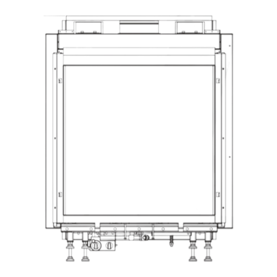
    INSTRUCTIONS D’INSTALLATION Important INSTRUCTIONS D’INSTALLATION • L’appareil doit être équipé d’un panneau de commande (fourni) ; lire à ce propos les instructions page 40. Sorte de gaz • Le manteau doit être ventilé, éventuellement à l’aide de Cet appareil est destiné au la pays et adapté au type de gaz ventilateurs DRU (2x) ou par le biais d’ouvertures ou de spécifié...
  • Page 57 INSTRUCTIONS D’INSTALLATION L’appareil Max fibre Max fibre Passage min de 200 cm fig. 1 Venteo...
  • Page 58: Panneau De Commande

    INSTRUCTIONS D’INSTALLATION Pour le montage, procédez inversement. L'appareil est livré Fixez le cadre extérieur avec volet ouvrant (4) au cadre avec étriers pour fixation au mur. Fixez l’appareil. intérieur à l’aide de deux vis Parker (5). Attention: Pour garantir un bon allumage, veillez à Vous pouvez fixer le cadre extérieur de façon à...
  • Page 59: Préparation De L'installation Du Système D'entrée Et D'évacuation

    INSTRUCTIONS D’INSTALLATION 2x45˚ 2x90˚ L=1+1+4+(2x2)=10 L=1+2+5+(2x1)=10 (H totaal= 5m) 1x90˚ 1x90˚ 38c-744b L=2+0,5+(2)=4,5 L=4+1+(2)=7 max 2m max 3m fig. 4 Attention: l’installation de cet appareil ne doit se faire conduit de traversée de la façade. Par matériel inflammable qu’au moyen du matériel d’évacuation ø150/ø100 fourni Ø...
  • Page 60: Cheminée Existante

    INSTRUCTIONS D’INSTALLATION • Raccordez le conduit de traversée du toit aux conduits Registre de restriction concentriques. Attention: Vous pouvez aussi poser les conduits concentriques d’abord, avant d’installer l’appareil. Dans ce cas servez-vous d’un conduit qui peut se raccourcir, pour le raccordement à la bouche de l’appareil. Cheminée existante Il est aussi possible de raccorder L’appareil à...
  • Page 61: Connexion De L'alimentation En Gaz

    INSTRUCTIONS D’INSTALLATION 38c-1084 Conduit d’arrivè e d’air Luchtinlaat geleider fig. 7 Connexion de l'alimentation en gaz en déplaçant la vermiculite, mais la couverture du brûleur doit rester bien couverte de vermiculite pour éviter de Dans le conduit d'alimentation, utilisez un robinet d'arrêt réduire la durée de vie du brûleur.
  • Page 62 INSTRUCTIONS D’INSTALLATION fig. 8 fig. 9 fig. 10 fig. 11 fig. 12 fig. 13 fig. 14...
  • Page 63: Vitrage

    INSTRUCTIONS D’INSTALLATION fig. 15 fig. 16 montage et tirez en même temps le vitrage sur le haut au Vitrage maximum vers vous. Après avoir installé le jeu de bûches/de cailloux, le vitrage • ! Attention: Tenez fermement la poignée supérieure. Si elle venait à...
  • Page 64 INSTRUCTIONS D’INSTALLATION • Attention: Fixez à nouveau la bande inférieure du vitrage à l’aide des 4 vis Parker. • Poussez les deux coins inférieurs vers le bas. • Poussez les coins supérieurs vers le haut de manière à ce que les deux bandes de fi xation appuient contre la vitre avec le cordon d’étanchéité.
  • Page 65 INSTRUCTIONS D’INSTALLATION fig. 24 fig. 25 fig. 26 fig. 27 fig. 28 Venteo...
  • Page 66: Mode D'emploi

    MODE D’EMPLOI MODE D’EMPLOI • Faites coulisser le couvercle pour le remettre en place. • Placez le récepteur tel qu’indiqué sur la Fig. 29. !Attention - Ne placez pas l’antenne du récepteur trop près Commande à distance sans fil du câble d’allumage et/ou d’éléments L'appareil est commandé...
  • Page 67: Créer Un Code De Communication

    MODE D’EMPLOI Vous pouvez éventuellement résoudre/éviter l’allumage !Attention - Lorsque vous appuyez sur les boutons involontaire de votre appareil en : (excepté le bouton SET), le symbole de - créant un nouveau code de communication entre la transmission ( ) apparaît pour vous indiquer commande à...
  • Page 68: Hauteur Des Flammes / Veille

    MODE D’EMPLOI - émet un bref signal sonore indiquant que le processus Heure d’allumage est terminé ; L’heure peut s’afficher sur l’écran. - connecte automatiquement l’appareil sur la position la plus Après avoir inséré la pile ou appuyé simultanément sur les élevée du brûleur principal ;...
  • Page 69: Activation De La Fonction Thermostat

    MODE D’EMPLOI !Attention - La température minimale réglable est de 5 ºC / Activation de la fonction de minuterie 40 ºF ; Pour activer le réglage horaire, procédez comme suit : - Le réglage de la température de nuit est •...
  • Page 70: Remarques Générales

    REMARQUES GÉNÉRALES REMARQUES GÉNÉRALES La première mise en service Lors de la première mise en service, l’évaporation de la Entretien et nettoyage laque peut provoquer une odeur désagréable. Cette odeur disparaîtra après quelques heures. Nous vous conseillons de Votre appareil doit être contrôlé chaque année par une chauffer la première fois l’appareil au maximum en prenant entreprise qualifiée.
  • Page 71 TECHNISCHE GEGEVENS,TECHNICAL DATA,TECHNISCHEN DATEN, DONNÉES TECHNIQUES VENTEO Type C11/C31 Gassoort,Type of gas, Gassorte, Sorte de gaz Branderdruk, Burner pressure, Brennerdruck, Pression de brûleur mbar 12.7 Nom. Belasting (Hs), Nom. Load (Hs), Nom. Belastung (Hs), Puissance calorifique (Hs) 7.70 8.00 Nom. Belasting (Hi), nom. Load (Hi), Nom. Belastung (Hi), Puissance calorifique (Hi) 6.90 7.20 Nom.Vermogen, Nom.

Table des Matières