Table des Matières

Publicité

Les langues disponibles

Les langues disponibles

Liens rapides

INSTALLATIEVOORSCHRIFT EN GEBRUIKERSHANDLEIDING NL/BE
INSTRUCTIONS FOR INSTALLATION AND OPERATION GB/IE
INSTALLATIONSVORSCHRIFT UND GEBRAUCHSANWEISUNG DE/AT/BE/LU/CH
INSTRUCTIONS D'INSTALLATION ET MODE D'EMPLOI FR/BE/LU/CH
PASSEO SL2
Bewaar dit document zorgvuldig
Please retain this document carefully
Bewahren Sie dieses Dokument sorgfältig auf
Conservez soigneusement cette notice
DRU VERWARMING B.V.
HOLLAND
957.578.12

Publicité

Table des Matières
loading

Sommaire des Matières pour Dru Verwarming PASSEO SL2

  • Page 1 INSTALLATIEVOORSCHRIFT EN GEBRUIKERSHANDLEIDING NL/BE INSTRUCTIONS FOR INSTALLATION AND OPERATION GB/IE INSTALLATIONSVORSCHRIFT UND GEBRAUCHSANWEISUNG DE/AT/BE/LU/CH INSTRUCTIONS D’INSTALLATION ET MODE D’EMPLOI FR/BE/LU/CH PASSEO SL2 Bewaar dit document zorgvuldig Please retain this document carefully Bewahren Sie dieses Dokument sorgfältig auf Conservez soigneusement cette notice DRU VERWARMING B.V.
  • Page 2 38c-1355...
  • Page 3 Belangrijk • Het toestel moet worden uitgerust met een bedieningsluik (meegeleverd),lees de instructies hier voor op pagina 4. • De boezem dient ontlucht te worden, evt met de beschikbare DRU ontluchters (2x) of anders door openingen of roosters met een minimale gezamelijke doorlaat van 200 cm •...
  • Page 4 Wichtig • Das Gerät muss mit einer Bedienungsluke (mitgeliefert) ausgerüstet werden. Lesen Sie hierzu die Instruktionen auf Seite 28. • Der Kaminüberbau muss entlüftet werden, evtl. mit den verfügbaren DRU-Entlüftern (2x), oder aber mit Öffnungen auf Rosten mit einem minimalen Gesamtdurchlass von 200 cm •...
  • Page 5 Passeo...
  • Page 6 Hierbij verklaren wij dat de DRU modellen Passeo in overeenstemming zijn met het CE type- onderzoekscertificaat E 1490 en dat zij voldoen aan de Europese richtlijn inzake gastoestellen 90/396/EEC. We here by declare that the DRU models Passeo are in conformity with the types as described in EC type-certificate E 1490 and that they are in compliance with the European Council gas appliance directive 90/396/EEC.
  • Page 7: Table Des Matières

    INHOUD INHOUD Instellen communicatiecode ....13 Belangrijk ........2 MAN stand .
  • Page 8: Belangrijk

    INSTALLATIEVOORSCHRIFT Belangrijk In dit boekje vindt u instructies voor installatie en gebruik van uw nieuwe toestel. Lees de instructies en • Het toestel moet worden uitgerust met een bedieningsluik gebruikershandleiding goed door, zodat u zich vertrouwd (meegeleverd),lees de instructies hier voor op pagina 4. maakt met het toestel.Wilt u meer ondersteuning, neem •...
  • Page 9 INSTALLATIEVOORSCHRIFT Haard Maximale stuc lijn Maximale stuc lijn fig. 1 Passeo...
  • Page 10: Bedieningsluikje

    INSTALLATIEVOORSCHRIFT De inbouwhoogte is afhankelijk van de instelling van de Monteer het gasregelblok aan de beugels (2) van het binnen frame. stelvoeten. Sluit de leidingen aan op de achterzijde van het Plaats vervolgens het toestel op de gewenste plaats. gasregelblok. Houd in de boezem enige ruimte rondom het toestel Let er op dat u de flexibele slang en de aluminium leiding zodat de warmte weg kan.Voor een goede warmte afvoer,...
  • Page 11: Voorbereidingen Voor Het Plaatsen Van Het In- En Uitlaatsysteem

    INSTALLATIEVOORSCHRIFT 2x45˚ 2x90˚ L=1+1+4+(2x2)=10 L=1+2+5+(2x1)=10 (H totaal= 5m) 1x90˚ 1x90˚ 38c-744b L=2+0,5+(2)=4,5 L=4+1+(2)=7 max 2m max 3m fig. 4 concentrische pijp en bochten worden per stuk verpakt • Bepaal de plaats van het toestel en van de plaats van de en compleet geleverd met een klemband voorzien van geveldoorvoer.
  • Page 12: Bestaande Schoorsteen

    INSTALLATIEVOORSCHRIFT • Zaag de buitenpijp af op de juiste lengte. Restrictieschuif • Sluit de dakdoorvoer aan op de concentrische pijpen. Let op: u kunt ook eerst de concentrische pijpen aanbrengen alvorens het toestel te plaatsen. U dient dan de aansluiting op de uitmonding van het toestel te maken met een inkortbare pijp.
  • Page 13: Aansluiting Van De Gastoevoer

    INSTALLATIEVOORSCHRIFT 38c-1084 Remplaat Luchtinlaat geleider fig. 7 Aansluiting van de gastoevoer om te voorkomen dat de levensduur van de brander afneemt. Gebruik in de toevoerleiding een gekeurde aansluitkraan met koppeling (voor België moet deze B.G.V. gekeurd zijn). Plaats stam A zoals aangegeven in figuur 10. Let hierbij op Verder geldt: de 3 referentiepunten zoals aangegeven in figuren 11, 12 •...
  • Page 14 INSTALLATIEVOORSCHRIFT fig. 8 fig. 9 fig. 10 fig. 11 fig. 12 fig. 13 fig. 14a fig. 14b...
  • Page 15: Glasraam

    INSTALLATIEVOORSCHRIFT fig. 15a fig. 15b fig. 16 Glasraam • Let op: Zorg ervoor dat u de bovenste handgreep stevig Na het plaatsen van de houtset kan het glasraam geplaatst vasthoudt. Als deze losschiet, kan het glasraam naar worden zoals hieronder is beschreven. binnen vallen en kan zowel het glasraam als het toestel ernstige schade oplopen;...
  • Page 16 INSTALLATIEVOORSCHRIFT • Tip: Probeer het glasraam met de bovenste handgreep naar u toe te trekken: als dit niet lukt, is het glasraam goed teruggeplaatst. • Let op: Zet de onderste strip van het glasraam weer vast met de 4 parkers. •...
  • Page 17 INSTALLATIEVOORSCHRIFT GEBRUIKERSHANDLEIDING fig. 24 fig. 25 fig. 26 fig. 27 fig. 28 Passeo...
  • Page 18: Gebruikershandleiding

    GEBRUIKERSHANDLEIDING GEBRUIKERSHANDLEIDING !Let op - Plaats de antenne van de ontvanger niet te dicht bij de ontstekingskabel en/of metalen delen: zorg ervoor dat de antenne omhoog Draadloze afstandsbediening wijst (zie voor de juiste positie fig. 29); Het toestel wordt bediend met een afstandsbediening. - Zorg ervoor dat de ontstekingskabel niet Zowel het ontsteken, het regelen van de vlamhoogte als over/langs metalen delen ligt: dit verzwakt de...
  • Page 19: Instellen Communicatiecode

    GEBRUIKERSHANDLEIDING maatregel als het toestel gedurende een lange periode - Het toestel gaat automatisch naar de stand-by stand als niet wordt gebruikt; er gedurende 6 uur geen transmissie plaatsvindt. - Neem - ook als het toestel niet in gebruik is - de •...
  • Page 20: Vlamhoogte / Stand-By

    GEBRUIKERSHANDLEIDING Thermostaat functie Als dit niet gebeurt, draait u de gaskraan dicht en waarschuwt u de installateur; U kunt met behulp van de thermostaat functie twee - Als het toestel met een plof ontsteekt, sluit u temperaturen instellen die thermostatisch geregeld worden. de gaskraan en waarschuwt u de installateur.
  • Page 21: Timer Voor Thermostaat Functie

    GEBRUIKERSHANDLEIDING Timer voor thermostaat functie !Let op - Let op de “+” en “-” polen van de batterij en de connector; Met behulp van de timer kunnen per etmaal twee tijden - Gebruik alkaline batterijen; ingesteld worden om de dagtemperatuur en twee tijden om de nachttemperatuur in te schakelen.
  • Page 22: Algemene Opmerkingen

    ALGEMENE OPMERKINGEN ALGEMENE OPMERKINGEN Eerste maal stoken Tijdens de eerste maal stoken kan er een onaangename Onderhoud en reiniging geur ontstaan, die wordt veroorzaakt door het uitdampen van de lak. Dit verdwijnt na enkele uren. Daarom raden wij Uw toestel dient eenmaal per jaar door een gekwalificeerd u aan het toestel de eerste maal op de hoogste stand te bedrijf te worden gecontroleerd, en waar nodig, hersteld stoken terwijl u tevens het vertrek waarin de kachel staat...
  • Page 23: Storingen

    STORINGEN PROBLEEM: MOGELIJKE OORZAAK: OPLOSSING: A. motor draait niet: 1. Bij de ontvanger moet er een nieuwe 1. Het resetknopje van de ontvanger ingedrukt communicatie sleutel (code) worden houden totdat u 2 geluidssignalen hoort. WAARSCHUWING: ingesteld: Laat na het tweede, langere geluidssignaal de Zorg dat er geen kortsluiting kan ontstaan tussen 2.
  • Page 24 STORINGEN PROBLEEM: MOGELIJKE OORZAAK: OPLOSSING: E. Geen Waakvlam: 1. Lucht in de waakvlamleiding. 1. Spoel de leiding of start het ontstekingsproces 2.Thermokoppeldraden verwisseld. meerdere keren opnieuw. 3. Geen vonk bij de waakvlam-brander. 2. Controleer de polariteit van de thermokoppelbedrading. 3. Probeer de klep handmatig te bedienen: Draai de knop A naar MAN en houd m.b.v.
  • Page 25 CONTENTS CONTENTS MAN position ......31 Important ........20 Ignition .
  • Page 26: Important

    INSTRUCTIONS FOR INSTALLATION Important Unpacking • The appliance should be fitted with a service flap Once the heater has been unpacked, all packaging should (provided), please read the instructions on page 16. be disposed of in the regular manner. • The chimney breast should be ventilated, e.g. with the DRU vents available (2x) or alternatively with openings or Connection grilles with a minimum total free vent area of 200 cm...
  • Page 27 INSTRUCTIONS FOR INSTALLATION Heater Max plaster line Max plaster line total free vent area of 200 cm fig. 1 Passeo...
  • Page 28: Service Flap

    INSTRUCTIONS FOR INSTALLATION We advise you to fit vents on both sides. First screw the thermocouple on by hand, and then tighten one quarter turn with the spanner. The DRU range includes suitable design vents. Take the box of logs and the bag of accessories out of the Place the receiver in the tray (3).
  • Page 29: Preparations For The Installation Of The Combined Inlet-Outlet System

    INSTRUCTIONS FOR INSTALLATION 2x45˚ 2x90˚ L=1+1+4+(2x2)=10 L=1+2+5+(2x1)=10 (H totaal= 5m) 1x90˚ 1x90˚ 38c-744b L=2+0,5+(2)=4,5 L=4+1+(2)=7 max 2m max 3m fig. 4 NB: This appliance may only be installed using the flue • Place the bend on top of this, fit any horizontal concentric material ø150/ø100 supplied by DRU.This has been pipes required, and make sure the connections are approved together with the appliance to comply with all...
  • Page 30: Fitting The Fire To An Existing Chimney

    INSTRUCTIONS FOR INSTALLATION Fitting the fire to an existing chimney Baffle The fire can be fitted into an existing chimney providing that the chimney / flue dimensions are 150 mm or more. A special flue kit is required, which can be obtained from Drugasar or a Drugasar agent.
  • Page 31: Connecting The Gas Supply

    INSTRUCTIONS FOR INSTALLATION 38c-1084 Air inlet baffle Luchtinlaat geleider fig. 7 Connecting the Gas Supply the burner floor must remain covered with vermiculite to avoid shortening the operational life of the burner. An approved connecting tap with coupling should be used in the supply hose (In Belgium this must be B.G.V.
  • Page 32 INSTRUCTIONS FOR INSTALLATION fig. 8 fig. 9 fig. 10 fig. 11 fig. 12 fig. 13 fig. 14a fig. 14b...
  • Page 33: Glass Window

    INSTRUCTIONS FOR INSTALLATION fig. 15a fig. 15b fig. 16 Glass window • Pull on the bottom handgrip to tilt the glass window in its After placing the wood/pebble set you can plac e the glass mounting towards you and, at the same time, pull the top window, as described below.
  • Page 34 INSTRUCTIONS FOR INSTALLATION For safety reasons a guard should be placed in • Check that the hook at the top of the glass window is in position in the seating / U-shaped strip. front of the fire at all times. •...
  • Page 35 INSTRUCTIONS FOR INSTALLATION fig. 24 fig. 25 fig. 26 fig. 27 fig. 28 Passeo...
  • Page 36: Operating Instructions

    OPERATING INSTRUCTIONS OPERATING INSTRUCTIONS !Caution - Do not place the antenna too close to the ignition cable and/or metal parts: make sure the antenna is pointing upwards (for the correct Wireless remote control position, see fig. 29); The appliance is supplied with a remote control. - Make sure the ignition cable is not running Ignition, controlling the flame height and switching off are over/alongside metal parts: this will weaken the...
  • Page 37: Setting The Communication Code

    OPERATING INSTRUCTIONS - when left unattended for a longer period, set button A - The appliance will automatically enter the on the gas control to the position MAN (see section; standby position, if there is no transmission for - close the gas tap near your appliance.This is the safest 6 hours.
  • Page 38: Flame Height / Standby

    OPERATING INSTRUCTIONS Thermostat function the main burner should be largely ignited within about 10 seconds. If this is not the case, you Using the thermostat function you can set two must close the gas tap and warn your installer; temperatures, which can be controlled thermostatically. - If the appliance ignites with a pop sound, you These temperatures are referred to as day temperature and must close the gas tap and contact your installer.
  • Page 39: Timer For Thermostat Function

    OPERATING INSTRUCTIONS Timer for thermostat function Replacing the battery Using the timer enables you to set two times per 24 hours If the battery is almost empty, the display will show “BATT”. for switching on the day temperature and two times per 24 hours for switching on the night temperature.
  • Page 40: General Notes

    GENERAL NOTES GENERAL NOTES Lighting the heater for the first time There can be an unpleasant smell when you light the Gas Safety Regulations (for installation & use) 1998 heater for the first time.This is caused by the varnish evaporating and will disappear after a few hours.We In your own interest and that of safety, it is law that all gas therefore advise you, on initial use, to heat the appliance at appliances are installed by competent persons in...
  • Page 41: Troubleshooting

    TROUBLESHOOTING OBSERVED PROBLEM: POSSIBLE CAUSE: REMEDY: A. No Transmission: 1. Receiver must learn new code. 1. Press and hold the receiver’s reset button (motor does not turn) 2. Dead batteries. until you hear 2 acoustic signals.After the 3. Receiver damaged. second longer acoustic signal release the WARNING: 4.Transmitter damaged.
  • Page 42 TROUBLESHOOTING OBSERVED PROBLEM: POSSIBLE CAUSE: REMEDY: G. Electronics continue to spark after 1. Receiver damaged. 1. Replace receiver and reprogram code positive pilot flame: (remedy 1). H. Positive pilot flame, but valve shuts 1.Receiver not programmed. 1. Remove battery from receiver. off after approximately 2.
  • Page 43 INHALT INHALT Einstellung des Kommunikationscodes ...49 Wichtig ........38 Betriebsmodus MAN .
  • Page 44: Wichtig

    INSTALLATIONSVORSCHRIFT Wichtig Der Ofen wird Standard mit einer drahtlosen Bedienung geliefert. Das Gerät ist mit einem stufenlos regelbaren • Das Gerät muss mit einer Bedienungsluke (mitgeliefert) Gasregelblock versehen. Die elektrische Speisung geschieht ausgerüstet werden. Lesen Sie hierzu die Instruktionen auf mittels Batterien.
  • Page 45 INSTALLATIONSVORSCHRIFT Gerät Max stuck leine Max stuck leine gesamt offnung Dürchlass von 200 cm fig. 1 Passeo...
  • Page 46: Bedienungsluke

    INSTALLATIONSVORSCHRIFT Ihnen, Glasfasertapete an Stelle von Stuck zu gebrauchen. Der Gasregelblock ist ab Fabrik unter das Gerät montiert. In der Praxis kann der Gasregelblock nicht unter dem Falls Sie doch Stuck anbringen lassen, müssen Sie darauf Gerät bleiben. Er muss abmontiert werden. achten, dass dieser nicht über die Flansche gearbeitet wird.
  • Page 47: Vorbereitung Für Den Einbau Des Zu- Ubd Abluftsystems

    INSTALLATIONSVORSCHRIFT 2x45˚ 2x90˚ L=1+1+4+(2x2)=10 L=1+2+5+(2x1)=10 (H totaal= 5m) 1x90˚ 1x90˚ 38c-744b L=2+0,5+(2)=4,5 L=4+1+(2)=7 max 2m max 3m fig. 4 Anforderungen entsprechen: konzentrischen Rohrsystems eingebaut wird, achten Sie • Immer erst 1 Meter Rohr vertikal anbringen, ausser bitte besonders auf die richtige Montageart. •...
  • Page 48: Dachdurchführung Mit Konzentrischen Rohren

    INSTALLATIONSVORSCHRIFT Dachdurchführung mit konzentrischen Rohren • Die Gesamtlänge darf nicht mehr als 12 m und nicht mehr als 3 m horizontal betragen. Eine Dachdurchführung kann in jeden Punkt des Daches münden, eventuell mit einer Verlängerung zum Dachfirst. Restriktionsschieber Die Dachdurchführung wird je nach einer der vorher genannten Möglichkeiten mit einer Klebeplatte für ein Im ein gutes Funktionieren des Gerätes zu gewährleisten, Flachdach geliefert, oder mit einer universell verstellbaren...
  • Page 49: Anschluß Der Gaszufuhr

    INSTALLATIONSVORSCHRIFT 38c-1084 Lufteinlass Gleitstück Luchtinlaat geleider fig. 7 Anschluß der Gaszufuhr Beachten Sie dabei Folgendes: Sie können das Flammenbild zwar beeinflussen, indem Sie das Vermiculit anders Gebrauchen Sie bei der Zufuhrleitung einen farbigen verteilen, aber die Brennerfläche muss mit dem Vermiculit Anschlußhahn mit Koppelung bedeckt sein, so dass die Lebensdauer des Brenners (für Belgien muß...
  • Page 50 INSTALLATIONSVORSCHRIFT Abb. 8 Abb. 9 Abb. 10 Abb. 11 Abb. 12 Abb. 13 Abb. 14a Abb. 14b...
  • Page 51: Glasscheibe

    INSTALLATIONSVORSCHRIFT Abb. 15a Abb. 15b Abb. 16 Glasscheibe • Die Glasscheibe mit dem unteren Handgriff durch die Öff Nach dem Einsetzen des Holzrahmens beziehungsweise nung im Montagegestell hindurch nach vorn kippen und des Kieselrahmens kann die vordere Glasscheibe gemäß • Gleichzeitig die Glasscheibe an der Oberseite so weit wie der nachstehenden Beschreibung eingesetzt werden.
  • Page 52 INSTALLATIONSVORSCHRIFT Glasscheibe in der Fassung/in der U-förmigen Leiste sitzt. • Horizontale Zierleiste anbringen. • Tipp: Versuchen Sie, die Glasscheibe mit dem oberen • Vertikale Zierleisten anbringen. Handgriff zu sich hin zu ziehen:Wenn dies nicht gelingt, sitzt die Glasscheibe gut fest. •...
  • Page 53 INSTALLATIONSVORSCHRIFT Abb. 24 Abb. 25 Abb. 26 Abb. 27 Abb. 28 Passeo...
  • Page 54: Gebrauchsanweisung

    GEBRAUCHSANWEISUNG GEBRAUCHSANWEISUNG • Den Deckel zurückschieben. • Den Empfänger wie in Abb. 29 dargestellt einbauen. Die drahtlose Fernbedienung !Achtung - Die Antenne des Empfängers nicht zu nah am Zur Bedienung des Geräts wird eine kabellose Zündkabel beziehungsweise Metallteilen Fernbedienung verwendet. montieren: sorgen Sie dafür, dass die Antenne Die Zündung, das Einregeln der Flammenhöhe sowie das nach oben zeigt (die richtige Position...
  • Page 55: Einstellung Des Kommunikationscodes

    GEBRAUCHSANWEISUNG Vor der unbeabsichtigten Zündung Ihres Geräts können !Achtung - Bei der Tastenbetätigung (ausgenommen der Sie sich möglicherweise schützen, indem Sie: SET-Taste) erscheint das Sendesymbol ( - Einen neuen Kommunikationscode zwischen der Dieses Symbol bestätigt die Signalübertragung Fernbedienung und dem Empfänger einstellen; von der Fernbedienung an den Empfänger;...
  • Page 56: Flammenhöhe / Stand-By

    GEBRAUCHSANWEISUNG - Das Gerät schaltet automatisch auf den Hauptbrenner um, Flamme) blinkt die Zeitanzeige auf dem Display und die der innerhalb weniger Sekunden brennt. Zeit kann eingestellt werden. • Betätigen Sie gleichzeitig die Tasten , bis die Achtung - Wenn die Zündflamme nach drei Zeitanzeige auf dem Display blinkt.
  • Page 57: Aktivieren Der Thermostatfunktion

    GEBRAUCHSANWEISUNG Aktivieren der Thermostatfunktion TIMER und P2 TIMER ein. • Mit der SET-Taste aktivieren Sie die (P*) TIMER-Funktion. Die Thermostatfunktion wird schrittweise wie folgt aktiviert: Auswechseln der Batterie • Schalten Sie das Gerät mit der -Taste (kleine Flamme) Wenn die Batterie fast leer ist, erscheint die Anzeige auf Stand-By (Zündflamme) um.
  • Page 58: Allgemeine Bemerkungen

    ALLGEMEIME BEMERKUNGEN ALLGEMEINE BEMERKUNGEN Zum ersten Mal heizen Wenn zum ersten Mal mit dem Gerät geheizt wird, kann Wartung und Reinigung ein unangenehmer Geruch entstehen. Dieser wird durch Lackdämpfe verursacht und verschwindet nach einigen Ihr Gerät muss einmal pro Jahr von einem qualifizierten Stunden von selbst.Wir empfehlen Ihnen deshalb, das Betrieb kontrolliert werden und falls nötig, repariert oder Gerät bei der ersten Inbetriebnahme in den höchsten...
  • Page 59: Storungen

    STÖRUNGEN PROBLEM: MÖGLICHE URSACHE: AUFLÖSUNG: A. Motor läuft nicht: 1. Bei dem Empfänger muss ein neuer 1. Den Resetknopf vom Empfänger eingedrückt Kanalcode eingestellt werden: halten, bis Sie 2 Signaltöne hören. Lassen Sie WARNUNG: 2.Verbrauchte Batterien. nach dem zweiten, längeren Signalton den Sorgen Sie dafür, dass kein Kurzschluss entstehen 3.
  • Page 60 STÖRUNGEN PROBLEM: MÖGLICHE URSACHE: AUFLÖSUNG: D. Ein durchlaufender Signal- ton von 5 1. AN/AUS-Schalter steht auf AUS. 1. Setzen Sie den Schalter auf AN. Sekunden 2. Lose Bedrahtung. 2. Schließen Sie die Bedrahtung gut an. (Möglicherweise gibt es 7 kurze Pieptöne 3.
  • Page 61 TABLE DES MATIÈRES TABLE DES MATIÈRES Remplacement des piles ..... .66 Important ........56 Commande à...
  • Page 62: Important

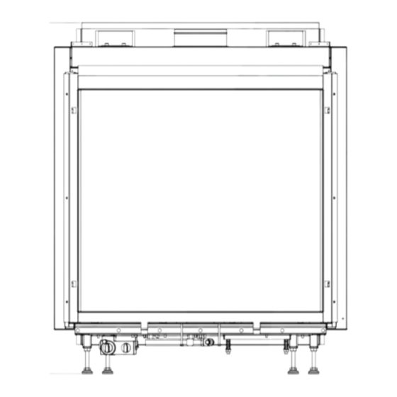
    INSTRUCTIONS D’INSTALLATION Important Lisez avec attention toutes les instructions ainsi que le • L’appareil doit être équipé d’un panneau de commande manuel de l'utilisateur afin de vous familiariser avec cet (fourni) ; lire à ce propos les instructions page 40. appareil.
  • Page 63 INSTRUCTIONS D’INSTALLATION L’appareil Max fibre Max fibre Passage min de 200 cm fig. 1 Passeo...
  • Page 64: Panneau De Commande

    INSTRUCTIONS D’INSTALLATION l’appareil (400 mm). L'appareil doit être monté à quelque Raccorder les tuyaux à l’arrière de l’unité de réglage du gaz. distance du mur arrière. Veiller à ce que le tuyau flexible et le conduit aluminium ne La hauteur de la cavité dépend du réglage des pattes. contiennent pas de gaz pendant le raccordement.
  • Page 65: Préparation De L'installation Du Système D'entrée Et D'évacuation

    INSTRUCTIONS D’INSTALLATION 2x45˚ 2x90˚ L=1+1+4+(2x2)=10 L=1+2+5+(2x1)=10 (H totaal= 5m) 1x90˚ 1x90˚ 38c-744b L=2+0,5+(2)=4,5 L=4+1+(2)=7 max 2m max 3m fig. 4 Le conduit de traversée de la façade avec des La longueur maximale totale correspond à la somme de la longueur de tuyau plus la longueur de remplacement pour conduits concentriques.
  • Page 66: Cheminée Existante

    INSTRUCTIONS D’INSTALLATION Registre de restriction • Faites un trou d’un diamètre de Ø 160 mm pour le ±0.5 ±0.5 conduit de traversée du toit. Par matériel inflammable Ø ±0.5 Afin de s’assurer du bon 230 mm. fonctionnement de l’appareil, il est •...
  • Page 67: Connexion De L'alimentation En Gaz

    INSTRUCTIONS D’INSTALLATION 38c-1084 Conduit d’arrivè e d’air Luchtinlaat geleider fig. 7 Connexion de l'alimentation en gaz en déplaçant la vermiculite, mais ; la couverture du brûleur doit rester bien couverte de Dans le conduit d'alimentation, utilisez un robinet d'arrêt vermiculite pour éviter de réduire la durée de vie du agréé...
  • Page 68 INSTRUCTIONS D’INSTALLATION fig. 8 fig. 9 fig. 10 fig. 11 fig. 12 fig. 13 fig. 14a fig. 14b...
  • Page 69: Vitrage

    INSTRUCTIONS D’INSTALLATION fig. 15a fig. 15b fig. 16 montage et tirez en même temps le vitrage sur le haut au maximum vers vous. Vitrage • ! Attention: Tenez fermement la poignée supérieure. Si Après avoir installé le jeu de bûches/de cailloux, le vitrage elle venait à...
  • Page 70 INSTRUCTIONS D’INSTALLATION • Attention: Fixez à nouveau la bande inférieure du vitrage à l’aide des 4 vis Parker. • Poussez les deux coins inférieurs vers le bas. • Poussez les coins supérieurs vers le haut de manière à ce que les deux bandes de fi xation appuient contre la vitre avec le cordon d’étanchéité.
  • Page 71 INSTRUCTIONS D’INSTALLATION fig. 24 fig. 25 fig. 26 fig. 27 fig. 28 Passeo...
  • Page 72: Mode D'emploi

    MODE D’EMPLOI MODE D’EMPLOI • Faites coulisser le couvercle pour le remettre en place. • Placez le récepteur tel qu’indiqué sur la Fig. 29. !Attention - Ne placez pas l’antenne du récepteur trop près Commande à distance sans fil du câble d’allumage et/ou d’éléments L'appareil est commandé...
  • Page 73: Créer Un Code De Communication

    MODE D’EMPLOI Vous pouvez éventuellement résoudre/éviter l’allumage !Attention - Lorsque vous appuyez sur les boutons involontaire de votre appareil en : (excepté le bouton SET), le symbole de - créant un nouveau code de communication entre la transmission ( ) apparaît pour vous indiquer commande à...
  • Page 74: Hauteur Des Flammes / Veille

    MODE D’EMPLOI Heure - émet un bref signal sonore indiquant que le processus d’allumage est terminé ; L’heure peut s’afficher sur l’écran. - connecte automatiquement l’appareil sur la position la plus Après avoir inséré la pile ou appuyé simultanément sur les élevée du brûleur principal ;...
  • Page 75: Activation De La Fonction Thermostat

    MODE D’EMPLOI Activation de la fonction de minuterie !Attention - La température minimale réglable est de 5 ºC / 40 ºF ; Pour activer le réglage horaire, procédez comme suit : - Le réglage de la température de nuit est •...
  • Page 76: Remarques Générales

    REMARQUES GÉNÉRALES REMARQUES GÉNÉRALES La première mise en service Lors de la première mise en service, l’évaporation de la Entretien et nettoyage laque peut provoquer une odeur désagréable. Cette odeur disparaîtra après quelques heures. Nous vous conseillons de Votre appareil doit être contrôlé chaque année par une chauffer la première fois l’appareil au maximum en prenant entreprise qualifiée.
  • Page 77: Pannes

    PANNES PROBLEME: ORIGINE POSSIBLE: SOLUTION: A. Le moteur ne marche pas : 1. Programmer un nouveau code canal pour 1. Maintenir enfoncé le bouton Reset du le récepteur. récepteur jusqu’à l’émission de 2 bips ATTENTION : 2. Les piles sont usées. sonores.
  • Page 78 PANNES PROBLEME : ORIGINE POSSIBLE : SOLUTION : E. Pas de veilleuse : 1. De l’air s’est introduit dans la conduite 1. Purger la conduite ou redémarrer d’alimentation de la veilleuse. l’allumage plusieurs fois. 2. Le thermocouple est mal raccordé. 2.
  • Page 79 TECHNISCHE GEGEVENS,TECHNICAL DATA,TECHNISCHEN DATEN, DONNÉES TECHNIQUES PASSEO Type C11/C31 Gassoort,Type of gas, Gassorte, Sorte de gaz Branderdruk, Burner pressure, Brennerdruck, Pression de brûleur mbar 19.5 13.5 Nom. Belasting (Hs), Nom. Load (Hs), Nom. Belastung (Hs), Puissance calorifique (Hs) Nom. Belasting (Hi), nom. Load (Hi), Nom. Belastung (Hi), Puissance calorifique (Hi) Nom.Vermogen, Nom.

Table des Matières