
Manuels Connexes pour Horizon Hobby E-Flite L-13 Blanik 4.2m


Sommaire des Matières pour Horizon Hobby E-Flite L-13 Blanik 4.2m
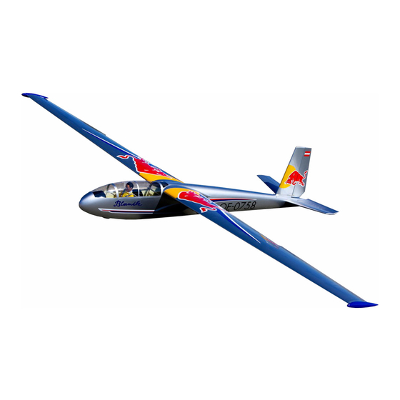
- Page 1 L-13 Blanik 4.2m ALMOST-READY-TO-FLY Instruction Manual Bedienungsanleitung Manuel d’utilisation Manuale di Istruzioni The Red Bull name and likeness is used under license of Red Bull GmbH Austria. www.modellmarkt24.ch...
-
Page 2: Using The Manual
Alle Anweisungen, Garantien und anderen zugehörigen Dokumente können im eigenen Ermessen discretion of Horizon Hobby, Inc. For up-to-date product literature, visit horizonhobby. com and von Horizon Hobby, Inc. jederzeit geändert werden. Die aktuelle Produktliteratur fi nden Sie auf click on the support tab for this product. -
Page 3: Utilisation Du Manuel
Horizon Hobby, Inc. Ce manuel maniera al di fuori delle istruzioni fornite da Horizon Hobby, Inc. Questo manuale contiene le comporte des instructions relatives à la sécurité, au fonctionnement et à l’entretien. Il est istruzioni per un funzionamento e una manutenzione sicuri. -
Page 4: Safety Warnings And Precautions
Verwenden Sie mit dem Produkt nur kompatible vous avez des questions concernant la compatibilité, riferimento alle istruzioni relative al prodotto o ai contact the appropriate Horizon Hobby offi ce. Komponenten. Sollten Fragen zur Kompatibilität référez-vous à ce manuel ou contactez le service... -
Page 5: Safe Operating Recommendations
SAFE OPERATING EMPFEHLUNGEN ZUM CONSIGNES DE SÉCURITÉ RACCOMANDAZIONI PER RECOMMENDATIONS SICHEREN BETRIEB CONCERNANT L’UTILISATION OPERARE IN SICUREZZA • Inspect your model before every fl ight to ensure it • Überprüfen Sie zur Flugtauglichkeit ihr Modell vor • Inspectez votre modèle avant chaque vol. •... - Page 6 ASSEMBLY SYMBOL GUIDE/MONTAGE SYMBOLE /GUIDE DES SYMBOLES POUR ASSEMBLÉE /GUIDA AI SIMBOLI DI ASSEMBLAGGIO Apply threadlock Ensure free rotation Use medium CA Use a pencil Schraubensicherungslack Rotation sicherstellen Mittelfl üssigen Verwenden Sie einen Bleistift verwenden Sekundenkleber verwenden Permettez une rotation libre Utilisez un crayon à...
- Page 7 hank you for purchasing this 1/4-scale model ielen Dank, dass Sie sich für den 1/4 Scale ous vous remercions pour l’achat du planeur razie per aver acquistato questo modello of the Red Bull sponsored aerobatic Blanik Red Bull Blanik entschieden haben. Mit den Blanik à...
-
Page 8: Replacement Parts/Ersatzteile/Pièces De Rechange/Ricambi
FASTENERS/VERBINDUNGSELEMENTE/LIAISONS/ELEMENTI DI FISSAGGIO M3 x 10 mm self-tapping screw (6) M3 x 10 mm fl at socket head (6) M3 washer (4) M4 x 30 wingbolt (2) M3 x 10mm selbstschneidene Schraube(6) M3 x 10 Senkkopfschraube (6) M3 Unterlegscheibe (4) M4 x30 Tragfl... - Page 9 Part English Deutsch Français Italiano SPMA3008 Heavy-Duty Y-Harness, 6-inch Spektrum Hochleistungs Y- Servokabel Cordon Y longueur 15 cm Prolunga a Y da 15cm per carichi pesanti SPM9530 Spektrum™ 3-Wire Switch Harness Spektrum Schalterkabel 3 Anschlüsse Interrupteur Spektrum à 3 fi ls Interruttore Spektrum 3 fi...
-
Page 10: Before Starting Assembly
BEFORE STARTING ASSEMBLY VOR DEM ZUSAMMENBAU AVANT DE COMMENCER PRIMA DI INIZIARE IL L’ASSEMBLAGE MONTAGGIO • Remove parts from bag. • Entnehmen Sie zur Überprüfung jedes Teil der Verpackung. • Retirez toutes les pièces des sachets pour les • Togliere tutti i pezzi dalla scatola. •... - Page 11 WING ASSEMBLY/ ZUSAMMENBAU DER TRAGFLÄCHEN/ ASSEMBLAGE DE L’AILE/ MONTAGGIO DELL’ALA/ Use low-tack tape to prevent epoxy from getting on the aileron and fl ap Lightly sand the control horn where it enters the control surface. surfaces. Schleifen Sie das Ruderhorn an den Kontaktstellen etwas an. Verwenden Sie Klebeband mit geringer Klebekraft um zu verhindern, dass Poncez légèrement la surface du guignol qui entre dans la gouverne.
- Page 12 Aileron/ Querruder/ Ailerons/ Alettone/ Flap/ Remove the tape before the epoxy fully cures. Klappen/ Volets/ Entfernen Sie das Klebeband bevor der Kleber getrocknet ist. Flap Retirez l’adhésif de masquage avant le séchage de la colle. Togliere il nastro adesivo prima che la colla si indurisca completamente. Insert the control horn in the slot in the control surface.
- Page 13 Aileron/ Front of the wing/ Querruder/ Vorderseite der Ailerons/ Tragfl äche/ Alettone/ Bord d’attaque de l’aile/ Bordo di entrata ala 3 mm 3 mm Flap/ Klappen/ Volets/ Flap Front of the wing/ Vorderseite der Tragfl äche/ Bord d’attaque de l’aile/ Hold the servo in place on the mounting blocks and mark screw locations Bordo di entrata ala with a felt tipped pen.
- Page 14 20mm 20mm 17mm 17mm Aileron/Querruder/ Flap/Klappen/ Ailerons/Alettone Volets/Flap Mount the servos to the blocks using a #1 screw driver. Glue the blocks Prepare the servo by centering the servo and preparing the servo horn. Use a pin vise with a 1/16” (1.5mm) drill bit to drill holes for the servo to the doors with 30 minute epoxy.
- Page 15 Use a #1 Phillips screwdriver and M2 x 8 mm self-tapping screws to Connect the 48” servo extension to the aileron servo lead and shrink secure the aileron servo cover. a 1 1/2” piece of 3/8” shrink tubing over the connection. Tie the string located inside the wing around the end of the extension.
- Page 16 OPTIONAL SPOILER INSTALLATION/ EINBAU DER OPTIONALEN STÖRKLAPPEN/ INSTALLATION DES AÉROFREINS OPTIONNELS/ INSTALLAZIONE AEROFRENI OPZIONALI/ IMPORTANT: If you are installing the optional E-fl ite retractable ® spoilers (EFL491009), use a receiver with 8 or more channels. At least 8 channels are required for correct operation. WICHTIG: Wenn Sie die optionalen E-fl...
- Page 17 Connect the spoiler to a servo driver or your radio system and fully open the spoiler. Schließen Sie die Störklappe an einen Servoanschluß des Empfängers ihrer Fernsteuerung an und fahren die Klappe vollständig aus. Connectez l’aérofrein à la rallonge de servo et déployez-le entièrement. Collegare l’aerofreno ad un provaservi o al radiocomando per aprirlo completamente.
- Page 18 Apply a small amount of 5-minute epoxy to the retractable center portion Mount the spoiler to the channel in the wing using a #1 screwdriver. Fully retract the spoiler. of the spoiler only, then tape the spoiler cover in place. Avoid getting Thread the three included self-tapping screws into the pre-drilled holes.
- Page 19 FLAP INSTALLATION/ EINBAU DER LANDEKLAPPEN/ INSTALLATION DES VOLETS/ INSTALLAZIONE FLAP/ Tie the string located inside the wing around the end of the extension. Connect the 18” servo extension to the fl ap servo lead, then shrink a Pull the lead through the wing. 1 1/2”...
- Page 20 Flap/ Klappen/ Volets/ Flaps/ Aileron/ Querruder/ Ailerons/ Alettoni/ 63 mm 100 mm Place the fl ap linkage into the slot in the wing. Connect the clevis to the fl ap control horn. Setzen Sie die Klappenanlenkung in die Tragfl äche ein. Schließen Sie den Gabelkopf am Klappenruderhorn an.
- Page 21 WINGTIP INSTALLATION/ MONTAGE DER TRAGFLÄCHENSPITZEN/ INSTALLATION DES SAUMONS D’AILES/ INSTALLAZIONE TERMINALI ALARI Connect the aileron linkage to the servo arm and control horn. Schließen Sie die Queruderanlenkung am Servo- und Ruderhorn an. Connectez la tringlerie d’ailerons entre le bras du servo et le guignol. Sand the mating surface of the wingtip to provide good adhesion.
- Page 22 Apply 5-minute epoxy to the mating surface. Before the epoxy cures, use rubbing alcohol and a paper towel to remove Use low tack tape to hold the wingtip in position while the glue cures. any excess. Geben Sie 5 Minuten Epoxy auf die angeschliffene Innenseite der Fixieren Sie die Flächenspitze mit Klebeband mit geringer Klebekraft Tragfl...
- Page 23 LANDING GEAR INSTALLATION/ EINBAU DES FAHRWERKS/ INSTALLATION DU TRAIN D’ATTERRISSAGE/ INSTALLAZIONE CARRELLO/ Mount the two upper mounting plates to one of the wheel supports using the included counter sunk machine screws and a 2 mm hex driver. Use threadlock on all screws. Ensure the counter sunk screw holes face out. Schrauben Sie mit den Senkkopfschrauben und einem 2mm Inbusschlüssel die beiden Haltestreben an die Seitenplatte.
- Page 24 Front/ Vorne/ Avant/ Davanti/ Install the wheel assembly into the fuselage with the taller vertical section to the front as shown in the above diagram. Setzen Sie den Radträger mit der größeren Seite nach vorne zeigend wie Mount the remaining wheel support plate. Secure the wheel assembly from inside the fuselage using four 3 x abgebildet in den Rumpf ein.
- Page 25 TAIL SURFACE HINGING/ MONTAGE DER LEITWERKE UND RUDER/ INSTALLATION DES CHARNIÈRES DE L’EMPENNAGE/ INCERNIERARE LA SUPERFICIE DI CODA/ Install the tail wheel into the slot on the bottom of the fuselage. Secure the wheel using the included M2 X 20 mm screw and lock nut. Setzen Sie das Spornrad in die Radöffnung ein und sichern Sie es mit Glue the rudder control horn into the slot in the tail surfaces following dem im Lieferumfang enthaltenen M2 x 20 Schrauben und Stopmuttern.
- Page 26 Apply 30-minute epoxy to the hinges mounted in the rudder and the holes in the vertical stabilizer. Install the rudder hinges into the holes in the stabilizer and use rubbing alcohol and a paper towel to remove any excess epoxy before it cures. Geben Sie 30 Minuten Epoxy auf die Scharniere des Seitenruders und in die Löcher des Höhenruders.
- Page 27 Test fi t the servo in the stabilizer half. Confi rm the spacing of the control horn with the pre-cut slot in the stabilizer surface. Use lite-ply spacers as necessary to align the servo so the servo arm will be centered in the slot.
- Page 28 Repeat steps 6–10 to assemble the other horizontal stabilizer half. Wiederholen Sie die Schritte 6–10 um die zweite Höhenruderhälfte zu montieren. Répétez les étapes de 6 à 10 pour assembler le deuxième demi-stab. Ripetere i passi da 6 a 10 per montare l’altra metà dello stabilizzatore orizzontale.
- Page 29 ELEVATOR INSTALLATION/ EINBAU DES HÖHENLEITWERKS/ INSTALLATION DU STABILISATEUR/ INSTALLAZIONE DELL’ELEVATORE/ Insert the carbon rods for mounting the horizontal stabilizer into one stabilizer half. Stecken Sie die Carbonstäbe in eine Höhenleitwerkshälfte Insérez les clés en carbone dans un des demi-stabilisateurs. Inserire le baionette in carbonio per montare lo stabilizzatore orizzontale nell’altra metà...
- Page 30 Tie a washer or other weight to one end of a piece of string. Hold the fuselage vertical (nose down), and feed the weight through the Tie the end of the string around the extension connected to the elevator front-most hole where the horizontal stabilizer mounts. Allow the weight servo.
- Page 31 VERTICAL STABILIZER INSTALLATION/ EINBAU DES SEITENLEITWERKS/ INSTALLATION DE LA DÉRIVE/ INSTALLAZIONE IMPENNAGGIO VERTICALE/ Sand the mating surface of the vertical stabilizer and fuselage for good adhesion Schleifen Sie die Klebefl äche des Seitenleitwerks am Rumpf für eine Apply 30-minute epoxy to the included carbon rods to align the vertical saubere Verklebung an.
- Page 32 Slide the rods in place and ensure the vertical stabilizer is fully seated. Clean any excess epoxy with rubbing alcohol and paper towels. Schieben Sie die Stangen ein und achten darauf dass das Seitenleitwerk Apply 30-minute epoxy to the carbon rods mounted in the vertical vollständig eingepaßt ist.
- Page 33 PULL-PULL CABLE PREPARATION/ MONTAGE DER PULL-PULL KABEL/ PRÉPARATION DU CÂBLE ALLER-RETOUR/ PREPARAZIONE DEL CAVO PULL-PULL/ Straighten the included pull-pull cable and cut it in half with side cutters. Ziehen Sie die im Lieferumfang enthaltenen Kabel stramm und schneiden diese in zwei gleich lange Hälften. Tendez le câble inclus et coupez-le en 2 à...
- Page 34 Carefully crimp the sleeve with side cutters. Trim any excess cable end. Enlarge the openings in the fuselage as necessary to allow the cable end Hold the fuselage vertical (nose down). Insert the threaded cable end and sleeve to fi t. into the opening.
- Page 35 RUDDER SERVO INSTALLATION/ EINBAU DES SEITENRUDERSERVOS/ Repeat steps 1–5 to assemble the cable for the opposite side. INSTALLATION DU SERVO DE DÉRIVE/ Wiederholen Sie die Schritte 1-5 für das Kabel auf der anderen Seite. INSTALLAZIONE SERVO TIMONE/ Répétez les étapes de 1 à 5 pour assembler le câble du côté opposé. Ripetere i passi da 1 a 5 per inserire il cavetto dall’altro lato.
- Page 36 50mm (DUB671) Install the servo using the self-tapping screws included with the servo. Prepare the servo by centering the output shaft, preparing the servo arm, and installing the bushings and grommets. Schrauben Sie das Servo mit den mitgelieferten selbstschneidenen Schrauben fest. Setzen Sie die Gummitülle und Blechösen ein, zentrieren Sie das Servo Use a pin vise with a 1/16”...
- Page 37 RUDDER HORN CONNECTIONS/ RUDERHORNANSCHLÜSSE/ LIAISON DU GUIGNOL DE DÉRIVE/ COLLEGAMENTI ALLA SQUADRETTA TIMONE/ Thread the clevises and nuts onto the servo end of the pull-pull cables. Assemble a threaded cable end, nut, and clevis as shown in the diagram Ensure the pull-pull cables cross inside the fuselage, but are not twisted above.
- Page 38 Install the clevis assembly on the rudder horn. Use tape or some other means to hold the rudder in alignment with Using the mark on the cable as a guide for the fi nished length, follow the fi n. Pull the cable taut and mark the point where the cable should the procedure shown in steps 1–3 of the “Pull-Pull Cable Preparation”...
- Page 39 TOW RELEASE INSTALLATION/ EINBAU DER SCHLEPPKUPPLUNG/ Repeat steps 1–4 to complete the other side of the rudder horn connection. Adjust the length of the connections by turning the clevis INSTALLATION DU CROCHET DE on the threaded cable ends to achieve taut cables on both sides of the REMORQUAGE/ rudder horn.
- Page 40 Install the servo with the self-tapping screws, bushings, and grommets Thread the clevis and nut onto the pre-bent tow release pushrod as Install the tow release in the pre-drilled hole and connect the clevis to included with the servo. Center the output shaft and install the servo shown above.
- Page 41 ELECTRONICS INSTALLATION/ EINBAU DER ELEKTRONIK/ INSTALLATION DE L’ÉLECTRONIQUE/ INSTALLAZIONE DELL’ELETTRONICA/ Engaged/ Retracted/ Geschlossen/ Offen/ Verrouillé/ Relâché/ Bloccato/ Retratto/ Ensure the tow release fully engages the front pin slot when closed and Attach a piece of hook and loop tape (included) to the receiver. Plug the fully retracts when open.
- Page 42 Mount the switch to the fuselage side at a convenient location where you Temporarily install the battery on the fl oor of the fuselage at the nose. Install the receiver in a location that provides easy wire routing. will have easy access to turn the model on and off and a clear path for Montieren Sie vorübergehend den Akku auf dem Rumpfboden im Bug.
- Page 43 COCKPIT DETAIL INSTALLATION/ COCKPITAUSBAU/ INSTALLATION DES ÉLÉMENTS INTÉRIEURS DU COCKPIT/ DETTAGLI PER L’INSTALLAZIONE DELL’ABITACOLO/ Install the remote receiver with the antennas mounted perpendicular to Trim the instrument consoles to fi t with hobby scissors. the antennas on the main receiver. If the main receiver’s antennas are Schneiden Sie das Instrumentenbrett mit der Schere zurecht.
- Page 44 WING INSTALLATION/ MONTAGE DER TRAGFLÄCHEN/ INSTALLATION DE L’AILE/ INSTALLAZIONE DELL’ALA/ NOTICE: Complete steps 1–5 of the wing installation before the epoxy cures on the wing alignment pin. If the epoxy cures before the wing is properly aligned, it could result in unexpected fl ight characteristics, possibly causing a crash.
- Page 45 Apply low tack tape to the fuselage around the wing alignment pin hole. Slide the wing tube into the fuselage until it is centered. Mix 30-minute epoxy and micro balloons, then apply it to the wing Apply petroleum jelly to the wing alignment pin hole and surrounding area alignment pin hole in the wing.
- Page 46 Slide the wing onto the wing tube until the wing meets with the fuselage. Repeat steps 1–5 to install the opposite wing panel alignment pin. Make sure the wing tube stays centered and that the alignment pin Wiederholen Sie die Schritte 1–5 um den Flächenstift auf der anderen slides into the alignment hole in the fuselage.
-
Page 47: Balancing The Aircraft
BALANCING THE AIRCRAFT CENTRAGE DE L'APPAREIL An important part of preparing the aircraft for fl ight is properly balancing Une des étapes importantes de la préparation d’un modèle est son After the epoxy fully cures, remove the wingbolts, wings and tape from the model. - Page 48 15-20mm With the model fully assembled, tape a plastic bag to the nose Disassemble the wings and remove the battery. Mix 30-minute epoxy, and fi ll it with ballast (lead shot works well) to achieve a balance location micro balloons and ballast. Glue the ballast into the nose of the glider 5/8–13/16”...
-
Page 49: Control Throws
CONTROL THROWS RUDERAUSSCHLÄGE 1. Turn on the transmitter and receiver of your model. Check the 1. Schalten Sie den Sender und Empfänger ihres Modells ein. Prüfen movement of the rudder using the transmitter. When the stick is moved Sie die Seitenruderaussschläge mit dem Sender. Bewegen Sie den to the right, the rudder should also move right. -
Page 50: Débattements
DÉBATTEMENTS CORSE DEI COMANDI PREFLIGHT CHECKLIST 1. Mettez l’émetteur et le récepteur sous tension. Contrôlez les 1. Accendere trasmettitore e ricevitore del modello. Controllare i • Charge the radio system the night before each fl ying session. mouvements de la dérive en utilisant votre émetteur. Quand le manche movimenti del timone agendo sul trasmettitore. -
Page 51: Contrôles Systématiques
CHECKLIST D’AVANT VOL DAILY FLIGHT CHECKS CONTRÔLES SYSTÉMATIQUES • Rechargez votre système radio la nuit avant chaque session de vol. • Check the battery voltage of the transmitter battery. Do not fl y below • Contrôlez la tension de la batterie de l’émetteur. Ne volez jamais en Chargez les batteries de l’émetteur et du récepteur en utilisant the manufacturer’s recommended voltage. -
Page 52: Flying Your Model
FLYING YOUR MODEL/ FLIEGEN DES MODELLS Die Landung mit dem Blanik ist sehr einfach. Fahren Sie die Klappen auf 20°, halten die Nase unten. Das Flugzeug wird dabei langsamer werden Sollte der Blanik ihr erstes grosses Modellsegelfl ugzeug sein ist und sie können die Maschine problemlos abfangen und aufsetzen. - Page 53 Durant vos premiers remorquages nous vous recommandons de ne pas Il Blanik volerà in quello che si dice una posizione alta del gancio di traino. dépasser une altitude de 150-180m. Plus vous irez haut, plus il est Questo è normale e non è necessario fare alcuna compensazione. I ganci diffi...
- Page 54 What this Warranty Covers Non-Warranty Service Horizon Hobby, Inc., (Horizon) warrants to the original purchaser that the These terms are governed by Illinois law (without regard to confl ict of law Should your service not be covered by warranty, service will be product purchased (the “Product”) will be free from defects in materials...
-
Page 55: Garantie Und Service Informationen
Wert des Produktes hinaus gehen. Horizon hat keinen Einfl uss auf eine Telefonnummer für Rückfragen, sowie eine Email Adresse. den Einbau, die Verwendung oder die Wartung des Produktes oder Exklusive Garantie ¬ Horizon Hobby Inc (Horizon) garantiert, dass Garantie und Reparaturen etwaiger Produktkombinationen, die vom Käufer gewählt werden. Horizon das gekaufte Produkt frei von Materialund Montagefehlern ist. -
Page 56: Garantie Et Réparations
Garantie et réparations aucune infl uence sur le montage, l’utilisation ou la maintenance du Garantie exclusive - Horizon Hobby, Inc. (Horizon) garantit que le Produit produit ou sur d’éventuelles combinaisons de produits choisies par Les demandes en garantie seront uniquement traitées en présence d’une acheté... -
Page 57: Durata Della Garanzia
Riparazioni a pagamento condizioni, limitazioni e riserve di garanzia citate in questa sede. Garanzia esclusiva - Horizon Hobby, Inc., (Horizon) garantisce che i Se bisogna effettuare una riparazione a pagamento, effettueremo un Qualora l’utente non fosse pronto ad assumersi tale responsabilità... -
Page 58: Contact Information
Harlow, Essex, CM18 7NS, United Kingdom +44 (0) 1279 641 097 Horizon Technischer Service service@horizonhobby.de Christian-Junge-Straße 1 Germany 25337 Elmshorn, Germany Sales: Horizon Hobby GmbH +49 (0) 4121 2655 100 infofrance@horizonhobby.com Service/Parts/Sales: 11 Rue Georges Charpak France Horizon Hobby SAS... -
Page 59: Ama National Model Aircraft Safety Code
AMA NATIONAL MODEL AIRCRAFT used provided they remain attached to the model during fl ight. Model Regulations, excluding takeoff and landing, no powered model may be rockets may be fl own in accordance with the National Model Rocketry fl own outdoors closer than 25 feet to any individual, except for the pilot SAFETY CODE Safety Code but may not be launched from model aircraft. - Page 60 © 2013 Horizon Hobby, Inc. E-fl ite, Celectra, Hangar 9, and DSMX are trademarks or registered trademarks of Horizon Hobby, Inc. The Spektrum trademark is used with permission of Bachmann Industries, Inc. The Red Bull name and likeness is used under license of Red Bull GmbH Austria.