Table des Matières

Publicité

Les langues disponibles

Les langues disponibles

Liens rapides

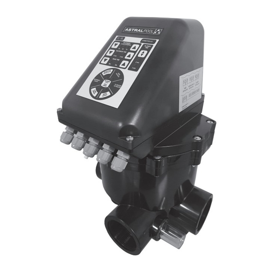
SIBO 2" AUTOMATIC MULTIPORT VALVE
SIBO 2" AUTOMATISCHE MEERWEGKLEP
SIBO 2" AUTOMATISCHES MEHRWEGEVENTIL
VANNE MULTIVOIE AUTOMATIQUE SIBO 2"
INSTALLATION AND MAINTENANCE MANUAL
HANDLEIDING VOOR INSTALLATIE EN ONDERHOUD
INSTALLATIONS- UND WARTUNGSANLEITUNG
MANUEL D'INSTALLATION ET D'ENTRETIEN
Modbus® is a registered trademark of the Modbus
Organization, Inc.

Publicité

Table des Matières
loading

Sommaire des Matières pour Astralpool 73082

  • Page 1 SIBO 2” AUTOMATIC MULTIPORT VALVE SIBO 2" AUTOMATISCHE MEERWEGKLEP SIBO 2” AUTOMATISCHES MEHRWEGEVENTIL VANNE MULTIVOIE AUTOMATIQUE SIBO 2” INSTALLATION AND MAINTENANCE MANUAL HANDLEIDING VOOR INSTALLATIE EN ONDERHOUD Modbus® is a registered trademark of the Modbus Organization, Inc. INSTALLATIONS- UND WARTUNGSANLEITUNG MANUEL D'INSTALLATION ET D'ENTRETIEN...
  • Page 2 This appliance can be used by children aged from 8 years and above and persons with reduced physical, sensory or mental capabilities or lack of experience and knowledge if they have been given supervision or instruction concerning use of the appliance in a safe way and understand the hazards involved.
  • Page 3: Ec Declaration Of Conformity

    System VRAC SIBO 230 Vca - 50 Hz for automatic multiport valves. Models: 73082, 73082-9000 meets the requirements established by the European Union according to the Directives: - Low Voltage Directive 2014/35/EC in accordance with the standards: EN 60335-1: 2012 + A13:2017 + A11:2014 + AC:2014 Household and similar electrical appliances - Safety - Part 1: General requirements.
  • Page 4 ENGLISH "Important: This instruction manual contains basic information with respect to safety measures which should be adopted during installation and putting into service. For this reason, it is essential that both the installer and user carefully read these instructions before carrying out any installation or putting into service operations."...
  • Page 5: Important

    ENGLISH ADVICE DURING INSTALLATION AND ASSEMBLy OPERATIONS. Make all the electrical connections by following the instructions in this manual. It should be verified that the electrical wiring connections to the valves electronic card are firmly made. The seal on the module’s box should be checked for correct positioning to prevent the entry of water, it should also be checked that the compression gland is also correctly located and that the cables are of a correct length.
  • Page 6: Table Des Matières

    ENGLISH CONTENTS Valve characterisctics. Specifications Flow diagram for the various valve operating positions. 1.2.1 Filtration position 1.2.2 Backwash position 1.2.3 Rinse position 1.2.4 Closed position 1.2.5 Recirculation position Installation. 2.1 Hydraulic installation 2.2 Electrical connection. 2.3 Fuse. Maintenance and guarantee. 3.1 Hydraulic installation maintenance.
  • Page 7: Valve Characterisctics

    ENGLISH 1. VALVE CHARACTERISTICS 1.1 SPECIfICATIONS. 2” Multiport valve actioned by System VRAC automatic device. The valve assembly to the filter will be LATERAL (side to the filter) in position 2. Materials: Valve body: ABS. Internal distributor: PPO. Spring: AISI-302 coated stainless steel. Screws: AISI-316 stainless steel.
  • Page 8: Filtration Position

    ENGLISH 1.2.1 filtration position: The pump sucks water from the pond via the skimmer, bottom cleaner or drain; it is taken to the multiport valve (PUMP connection) and from the Bottom outlet of the valve to the inlet of the filter. It passes through the filter bed and returns to the valve once again via the Top connection and is taken back to the pond by the RETURN connection.
  • Page 9: Fuse

    ENGLISH - Power supply: 230 Vac. It is advisable to take the current from the terminal connection of the differential switch (if used), or else connect the L, N and T terminals from the thermal circuit breaker to the corresponding L, N and T terminals of the electronic module. This connection has no polarity. We recommend to use a 3 wire earthed cable of 0.75 mm (H05VV-F) with a cord diameter of 5 to 6,7 mm (Tightening torque: 1,5 Nm).
  • Page 10: Maintenance And Guarantee

    ENGLISH F 400mA L 250 V 3. MAINTENANCE AND GUARANTEES. 3.1 HyDRAULIC INSTALLATION MAINTENANCE Regular maintenance needs to be carried out on all components of the pond's hydraulic circuit in order to ensure optimum operation of the installation and thereby prevent damage to the valve or any other components.
  • Page 11: Guarantees

    ENGLISH 3.3 GUARANTEES. The valves leave the factory in a fully tested condition, which enables us to guarantee operation. The guarantee will be effective provided that the installation and maintenance has been correctly carried out and this requires that the actual installation operation be performed by a person with the necessary qualifications for this type of work.
  • Page 12: Washing Cycle

    ENGLISH 4.2 WASHING CyCLE 4.2.1 Washing cycle description Valve is normally in FILTERING position and the pump is running. Once the backwash cycle is activated, by time or by push-button, the cycle will be as follows: Filter Pump stops. Valve goes to BACKWASH position. Filter pump starts for 25 seconds.
  • Page 13: Drainage

    ENGLISH 4.4 DRAINAGE Press the waste button for 3 seconds. The electronic module will stop the pump and the valve will turn to “WASTE” position. The pump will start up again. To stop the drainage press the button briefly again. The module will stop the pump and it will be positioned in Filtration and will activate it again.
  • Page 14: Instructions For Removing The Module Installed On The Valve

    ENGLISH 5. INSTRUCTIONS fOR REMOVING THE MODULE INSTALLED ON THE VALVE The valve consists of two sections, the hydraulic part, which includes a conventional valve, and an automatic module. The complete valve is disassembled of the filter in the same way as a manual valve. 5.1 DISASSEMBLy Of THE ELECTRONIC MODULE: (See illustrations in APPENDIX 1) BEFORE ANY OPERATION IS CARRIED OUT ON THE VALVE, IT MUST BE DISCONNECTED FROM THE POWER SUPPLY.
  • Page 15: How To Change The Valve From Manual To Automatic Operation

    ENGLISH 5.4 HOW TO CHANGE THE VALVE fROM MANUAL TO AUTOMATIC OPERATION. Remove the pin (10) (APPENDIX 1 - Fig. 6), remove the handle (14) and install the part (7) (APPENDIX 1 - Fig. 5). This is accomplished by orienting the mark (A) such that it coincides with the triangle (APPEN- DIX 1 - Fig.
  • Page 16: Solution Of Possible Problems

    ENGLISH 7. SOLUTION Of POSSIBLE PROBLEMS. We attach a list of possible problems that can occur with the valve, together with the best solution. If the MODBUS communication bus is used, please consult the specific manual to solve the possible incidents. PROBLEM CAUSE SOLUTION...
  • Page 17: Warranty

    ENGLISH WARRANTy 1. This warranty applies only to sales made to consumers (individuals or bodies corporate that acquire the Product for purposes other than a business or professional activity). 2. In accordance with these provisions, the manufacturer hereby guarantees that the product corresponding to this warranty ("the Product") does not contain whatsoever non-conformity when it is delivered.
  • Page 18: Algemene Veiligheidsvoorschriften

    DUTCH "Belangrijk: Deze handleiding bevat essentiële informatie met betrekking tot de veiligheidsmaatrege- len die genomen moeten worden tijdens de installatie en de inwerkingstelling. Om deze reden is het zeer belangrijk dat zowel de installateur als de gebruiker deze instructies zorgvuldig lezen, alvorens het product te installeren of in werking te stellen."...
  • Page 19: Advies Tijdens Installatie En Montage

    DUTCH ADVIES TIJDENS INSTALLATIE EN MONTAGE Maak alle elektrische aansluitingen door het volgen van de instructies in deze handleiding. Controleer of de elektrische bedrading goed is aangesloten op de printplaat van de klep. Controleer of de afdichting op het kastje van de module goed is geplaatst zodat er geen water binnendringt, en controleer of de pakkingbus goed op zijn plaats zit en of de kabels de goede lengte hebben.
  • Page 20 DUTCH INHOUD Eigenschappen van de klep Specificaties Stroomdiagram voor de diverse bedrijfsstanden van de klep 1.2.1 Filtration-stand (filtratie) 1.2.2 Backwash-stand (reinigen) 1.2.3 Rinse-stand (spoelen) 1.2.4 Closed-stand (gesloten) 1.2.5 Recirculation-stand (recirculatie) Installatie 2.1 Hydraulische installatie 2.2 Elektrische aansluiting 2.3 Zekering Onderhoud en garantie 3.1 Onderhoud van de hydraulisch installatie 3.2 Onderhoud van de klep 3.3 Garanties...
  • Page 21: Specificaties

    DUTCH 1. EIGENSCHAPPEN VAN DE KLEP 1.1 SPECIfICATIES 2" meerwegklep die in werking wordt gezet door de automatische klep 'System VRAC' . De klep wordt ZIJWAARTS gemonteerd op het filter, in stand 2. Materialen: Kleplichaam: ABS. Interne verdeler: PPE. Veer: AISI-302 gecoat roestvrij staal. Schroeven: AISI-316 roestvrij staal.
  • Page 22: Filtration-Stand (Filtratie)

    DUTCH 1.2.1 filtration-stand (filtratie) De pomp zuigt water uit de vijver via de skimmer, bodemzuiger of afvoer, dat vervolgens wordt meegenomen naar de meerwegklep (PUMP-aansluiting), en van de onderste uitlaat van de klep naar de inlaat van het filter gaat. Het water gaat door het filterbed, keert terug naar de klep via de TOP-aansluiting en wordt teruggenomen naar de vijver via de RETURN-aansluiting.
  • Page 23: Zekering

    DUTCH - Voeding: 230 Vac. Aanbevolen wordt om de stroom van de eindaansluiting van de aardlekschakelaar (indien gebruikt) te nemen, of om de L-, N- en T-terminals van de thermische zekeringautomaat aan te sluiten op de overeenkomstige L-, N- en T-terminals van de elektronische module. Deze aansluiting heeft geen polariteit.
  • Page 24: Onderhoud En Garantie

    DUTCH Z 400 mA L 250 V 3. ONDERHOUD EN GARANTIE 3.1 ONDERHOUD VAN DE HyDRAULISCHE INSTALLATIE Regelmatig onderhoud moet worden uitgevoerd aan alle onderdelen van het hydraulisch circuit van de vijver voor een optimale werking van de installatie. Hierbij moet schade aan de klep en andere onderdelen worden vermeden.
  • Page 25: Garanties

    DUTCH 3.3 GARANTIES De kleppen verlaten de fabriek pas nadat alle onderdelen ervan volledig zijn getest, waardoor we een goede werking kunnen garanderen. De garantie op de kleppen is geldig op voorwaarde dat de installatie en het onderhoud correct worden uitgevoerd, wat inhoudt dat de feitelijke installatie moet worden uitgevoerd door een persoon met de benodigde kwalificaties voor dit soort werk.
  • Page 26: Reinigingscyclus

    DUTCH 4.2 REINIGINGSCyCLUS 4.2.1 Beschrijving reinigingscyclus De klep staat normaliter in de filtratiestand, waarbij de pomp aan het functioneren is. Zodra de reinigingscyclus wordt geactiveerd, via een programmering of via de druktoetsen, verloopt de cyclus als volgt: Filterpomp stopt. Klep gaat over in de BACKWASH-stand. Filterpomp start gedurende 25 sec.
  • Page 27: Afvoer

    DUTCH 4.4 AfVOER Druk gedurende drie seconden op de waste-toets. De elektronische module stopt de pomp en de klep gaat naar de WASTE-stand. De pomp start opnieuw. Om het afvoeren te stoppen, drukt u nogmaals kort op de toets. De module stopt de pomp, de klep gaat naar FILTRATION (filtratie) en start opnieuw. 4.5 GESLOTEN Om de klep in de CLOSED-stand (gesloten) te zetten, moet de klep eerst in de FILTRATION-stand (filtratie) staan en moet de pomp werken.
  • Page 28: Instructies Voor Het Verwijderen Van De Op De Klep Geïnstalleerde Module

    DUTCH 5. INSTRUCTIES VOOR HET VERWIJDEREN VAN DE OP DE KLEP GEÏNSTALLEERDE MODULE De klep bestaat uit twee delen: het hydraulische gedeelte met een traditionele klep en een automatische module. De complete klep wordt van het filter gedemonteerd op dezelfde wijze als een handmatige klep. 5.1 DEMONTAGE VAN DE ELEKTRONISCHE MODULE (Zie afbeeldingen in BIJLAGE 1) ALVORENS MET WERKZAAMHEDEN AAN DE KLEP TE BEGINNEN, MOET DE STROOM NAAR DE KLEP WORDEN UITGESCHAKELD.
  • Page 29: Omzetten Van De Klep Van Handmatige Naar Automatische Bediening

    DUTCH 5.4 OMZETTEN VAN DE KLEP VAN HANDMATIGE NAAR AUTOMATISCHE BEDIENING Verwijder de pin (10) (BIJLAGE 1 - Fig. 6), verwijder de hendel (14) en installeer het onderdeel (7) (BIJLAGE 1 - Fig. 5). Dit lukt door de markering (A) zo af te stellen dat deze overeenkomt met de driehoek (BIJLAGE 1 - Fig.
  • Page 30: Oplossing Van Mogelijke Problemen

    DUTCH 7. OPLOSSING VAN MOGELIJKE PROBLEMEN Hieronder treft u een lijst van mogelijke problemen met de klep en de beste oplossing hiervoor. Bij gebruik van de MODBUS-communicatiebus raadpleegt u de specifieke handleiding om mogelijke incidenten op te lossen. PROBLEEM OORZAAK OPLOSSING De klep start niet en de led Onjuiste elektrische aans-...
  • Page 31: Garantie

    DUTCH GARANTIE 1. Deze garantie is alleen van toepassing op verkoop aan consumenten (natuurlijke of rechtspersonen die het Product aanschaffen voor doeleinden anders dan een bedrijfs- of zakelijke activiteit). 2. Overeenkomstig deze bepalingen, garandeert de fabrikant bij dezen dat het product binnen onderhavige garantie (het "Product"), geen enkele niet-conformiteit bevat wanneer het wordt geleverd.
  • Page 32 DUTCH • Barsten, kleurveranderingen, vervormingen of enige andere wijziging wanneer het Product is gemaakt van natuurlijke producten, zoals hout of steen. Om deze symptomen tot een minimum te beperken, moeten de aanwijzingen op het onderhoudsblad dat met het Product is meegeleverd, worden opgevolgd. •...
  • Page 33: Allgemeine Sicherheitsvorschriften

    DEUTSCH "Wichtig: Diese Betriebsanleitung enthält grundlegende Informationen zu Sicherheitsmaßnahmen, die während der Installation und Inbetriebnahme zu berücksichtigen sind. Aus diesem Grund ist es unerlässlich, dass sowohl der Installateur als auch der Benutzer diese Anweisungen vor Installations- beginn oder Inbetriebnahme aufmerksam lesen. Um eine optimale Leistung des automatischen Ventils zu erzielen, wird die strikte Befolgung der unten stehenden Anweisungen empfohlen.
  • Page 34 DEUTSCH HINWEISE ZU INSTALLATIONS- UND MONTAGEARBEITEN. Stellen Sie die elektrischen Anschlüsse gemäß der Anweisungen in dieser Betriebsanleitung her. Überprüfen Sie den festen Sitz der elektrischen Verbindungen zur Leiterplatte. Die Dichtung des Modulkastens sollte auf korrekten Sitz kontrolliert werden, um das Eindringen von Wasser zu verhindern; ebenso sollte kontrolliert werden, ob die Stopfbuchse korrekt sitzt und die Kabel die richtige Länge haben.
  • Page 35 DEUTSCH INHALTSVERZEICHNIS Eigenschaften des Ventils. Spezifikationen Flussdiagramm für die verschiedenen Betriebspositionen des Ventils. 1.2.1 Position Filtern 1.2.2 Position Rückspülen 1.2.3 Position Nachspülen 1.2.4 Position Geschlossen 1.2.5 Position Zirkulieren Installation. 2.1 Hydraulische Installation 2.2 Elektrischer Anschluss. 2.3 Sicherung. Wartung und Garantie. 3.1 Wartung der hydraulischen Installation.
  • Page 36: Eigenschaften Des Ventils

    DEUTSCH 1. EIGENSCHAfTEN DES VENTILS 1.1 SPEZIfIKATIONEN. 2” Mehrwegeventil, gesteuert durch System VRAC automatische Vorrichtung. Das an den Filter montierte Ventil befindet sich SEITLICH (zur Seite des Filters) in Position 2. Materialien: Ventilkörper: ABS. Interner Verteiler: PPO. Feder: AISI-302 beschichteter Edelstahl. Schrauben: AISI-316 Edelstahl.
  • Page 37: Position Filtern

    DEUTSCH 1.2.1 Position filtern: Die Pumpe saugt über den Skimmer, den Bodensauger oder den Ablauf Wasser aus dem Becken an; es wird zu dem Mehrwegeventil geleitet (PUMP Anschluss) und dann vom Bodenauslass des Ventils zum Filtereinlass. Es läuft durch die Filterschicht und durch den Top-Anschluss wieder zurück zum Ventil, um durch den RETURN-Anschluss wieder zurück ins Becken geleitet zu werden.
  • Page 38: Sicherung

    DEUTSCH - Stromversorgung: 230 Vac. Es ist ratsam, den Strom aus der Anschlussklemme des Differentialschalters (falls vorhanden) zu nehmen, oder aber die L, N und T-Klemmen vom Thermoschutzschalter an die entsprechenden L, N und T-Klemmen des Elektronikmoduls anzuschließen. Dieser Anschluss hat keine Polarität.
  • Page 39: Wartung Der Hydraulischen Installation

    DEUTSCH F 400mA L 250 V 3. WARTUNG UND GEWÄHRLEISTUNGEN. 3.1 WARTUNG DER HyDRAULISCHEN INSTALLATION Eine regelmäßige Wartung ist an allen Komponenten des Hydraulikkreislaufs des Schwimmbeckens erforderlich, um einen optimalen Betrieb der Installation sicherzustellen und dadurch eine Beschädigung des Ventils oder anderer Komponenten vorzubeugen. Die untenstehend aufgelisteten Wartungsarbeiten können eine direkte Auswirkung auf den Betrieb des Mehrwegeventils haben: Stellen Sie sicher, dass die Skimmerkörbe regelmäßig geleert und gesäubert werden, um sie...
  • Page 40: Gewährleistungen

    DEUTSCH 3.3 GEWÄHRLEISTUNGEN. Die Ventile verlassen das Werk in einem umfassend geprüften Zustand, dadurch können wir den Betrieb gewährleisten. Die Gewährleistung ist nur dann wirksam, wenn die Installation und Wartung korrekt ausgeführt wurde; dies erfordert, dass die eigentliche Installationsarbeit von einer für diese Art von Arbeit qualifizierte Fachkraft ausgeführt wird.
  • Page 41: Spülzyklus

    DEUTSCH 4.2 SPÜLZyKLUS 4.2.1 Spülzyklus Beschreibung Das Ventil befindet sich normalerweise in der FILTERN-Position und die Pumpe läuft. Wenn der Rückspülen- Zyklus aktiviert wird, durch Zeitprogrammierung oder per Knopfdruck, läuft der Zyklus wie folgt ab: Filterpumpe hält an. Ventil geht auf RÜCKSPÜLEN-Position. Filterpumpe startet für 25 Sekunden.
  • Page 42: Entleerung

    DEUTSCH 4.4 ENTLEERUNG Drücken Sie den Entleeren-Knopf für 3 Sekunden. Das Elektronikmodul hält die Pumpe an und das Ventil geht auf “WASTE” Position. Die Pumpe startet wieder. Um die Entleerung zu beenden, drücken Sie kurz wieder den Knopf. Das Modul hält die Pumpe an und wird auf Filtern gestellt und aktiviert sie wieder.
  • Page 43: Anweisungen Zum Ausbau Des Im Ventil Installierten Moduls

    DEUTSCH 5. ANWEISUNGEN ZUM AUSBAU DES IM VENTIL INSTALLIERTEN MODULS Das Ventil besteht aus zwei Teilen, dem hydraulischen Teil, der ein konventionelles Ventil enthält, und ein Automatikmodul. Das komplette Ventil wird auf die gleiche Weise wie ein manuelles Ventil von dem Filter abmontiert.
  • Page 44: Wie Das Ventil Vom Manuellen Auf Automatischen Betrieb Umgestellt Wird

    DEUTSCH 5.4 WIE DAS VENTIL VOM MANUELLEN BETRIEB AUf AUTOMATISCHEN BETRIEB UMGESTELLT WIRD. Den Stift herausnehmen (10) (ANHANG 1 - Abb. 6), Griff abnehmen (14) und Teil (7) montieren (ANHANG 1 - Abb. 5). Dies geschieht durch die Ausrichtung der Markierung (A), so, dass sie mit dem Dreieck übe- reinstimmt (ANHANG 1 - Abb.
  • Page 45: Lösung Möglicher Probleme

    DEUTSCH 7. LÖSUNG MÖGLICHER PROBLEME. Im Anhang gibt es eine Auflistung möglicher Probleme, die bei dem Ventil auftreten können, zusammen mit deren jeweils besten Lösung. Wenn der MODBUS Kommunikationsbus verwendet wird, sehen Sie bitte in der speziellen Betriebsanleitung nach, um mögliche Störungen zu beheben. PROBLEM URSACHE LÖSUNG...
  • Page 46: Garantie

    DEUTSCH GARANTIE 1. Diese Garantie gilt nur für Käufe, die von Konsumenten getätigt wurden (physische oder juristische Personen, die das Produkt nicht für unternehmerische oder kommerzielle Zwecke erwerben). 2.Entsprechend den vorliegenden Ausführungen garantiert der Hersteller, dass das Produkt, auf das sich diese Garantie bezieht ("das Produkt), im Moment seiner Übergabe keinerlei Mängel aufweist.
  • Page 47 DEUTSCH • Nicht dem Produkt zurechenbare oder externe Ursachen, wie seine Lagerung im Freien oder an vers- chlossenen Orten, gemeinsam mit chemischen Produkten, an denen schadhafte Umfeldbedingungen vorliegen können. • Unkontrollierte Ablagerung von Reinigungsmitteln oder chemischen Produkten auf dem Produkt. •...
  • Page 48: Consignes Générales De Sécurité

    fRANÇAIS « Important : Ce manuel d'instructions contient des informations de base concernant les mesures de sécurité qui doivent être suivies pendant l'installation et la mise en service. Pour cette raison, il est essentiel que l'installateur et l'utilisateur lisent attentivement ces instructions avant de réaliser l'installation ou de mettre l'appareil en service. »...
  • Page 49: Conseil Pour La Mise En Service

    fRANÇAIS CONSEILS PENDANT L'INSTALLATION ET LES OPÉRATIONS D'ASSEMBLAGE. Réalisez toutes les connexions électriques en suivant les instructions de ce manuel. Vérifiez si les connexions du câblage électrique et de la carte électronique des vannes sont solides. Vérifiez le joint de la boîte du module pour voir si sa position est correcte afin d'empêcher une infiltration d'eau ; le presse-étoupe doit aussi être vérifié...
  • Page 50 fRANÇAIS SOMMAIRE Caractéristiques de la vanne Spécifications Schéma de circulation des différentes positions de fonctionnement de la vanne 1.2.1 Position de filtration 1.2.2 Position de lavage 1.2.3 Position de rinçage 1.2.4 Position fermée 1.2.5 Position de circulation Installation 2.1 Installation hydraulique 2.2 Raccordement électrique 2.3 Fusible Entretien et garantie...
  • Page 51: Caractéristiques De La Vanne

    fRANÇAIS 1. CARACTÉRISTIQUES DE LA VANNE 1.1 SPÉCIfICATIONS Vanne multivoie 2” automatique équipée du système VRAC. La vanne montée sur le filtre sera LATÉRALE (sur le côté du filtre) en position 2. Matériaux : Corps de la vanne : ABS. Distributeur interne : PPO. Ressort : revêtement en acier inoxydable AISI-302.
  • Page 52: Position De Filtration

    fRANÇAIS 1.2.1 Position de filtration La pompe aspire l'eau de la piscine par le skimmer, la bonde de fond ou la prise balai ; elle est emmenée vers la vanne multivoie (raccordement de la POMPE) et de la sortie inférieure de la vanne vers l'entrée du filtre.
  • Page 53: Fusible

    fRANÇAIS - Alimentation électrique : 230 ACC. Il est conseillé de prendre l'électricité à partir d'une borne de raccordement de l'interrupteur différentiel (si l'on en utilise un), ou de raccorder les bornes L, N et T du disjoncteur général thermique aux bornes L, N et T correspondantes du module électronique. Ce raccordement n'a pas de polarité.
  • Page 54: Entretien De L'installation Hydraulique

    fRANÇAIS F 400mA L 250 V 3. ENTRETIEN ET GARANTIES 3.1 ENTRETIEN DE L'INSTALLATION HyDRAULIQUE Un entretien régulier doit être fait sur tous les composants du circuit hydraulique du bassin afin d'assurer un fonctionnement optimal de l'installation et donc d'éviter d'endommager la vanne ou tout autre composant. Les opérations d'entretien qui ont un impact direct sur le fonctionnement de la vanne multivoie sont énumérées ci-dessous : Assurez-vous de vider et de laver régulièrement les paniers du skimmer afin qu'il n'y ait pas de...
  • Page 55: Garanties

    fRANÇAIS 3.3 GARANTIES. Les vannes quittent l'usine en ayant été totalement testées, ce qui nous permet de garantir leur fonctionnement. La garantie prendra effet à condition que l'installation et l'entretien aient été correctement réalisés ; il est donc indispensable que l'opération d'installation actuelle soit réalisée par un personne ayant les qualifications nécessaires pour ce type de travail.
  • Page 56: Cycle De Lavage

    fRANÇAIS CyCLE DE LAVAGE 4.2.1 Description du cycle de lavage La vanne est normalement sur la position FILTRAGE et la pompe fonctionne. Une fois le cycle de lavage activé, par programmation du temps ou par le bouton-poussoir, le cycle se déroulera comme suit : 1.
  • Page 57: Vidange

    fRANÇAIS 4.4 VIDANGE Appuyez sur le bouton de vidange pendant 3 secondes. Le module électronique arrêtera la pompe et la vanne se mettra sur la position VIDANGE. La pompe redémarrera. Pour stopper la vidange appuyez brièvement sur le bouton. Le module arrêtera la pompe, elle sera positionnée sur Filtration et l'activera à...
  • Page 58: Instructions Pour Enlever Le Module Installé Sur La Vanne

    fRANÇAIS 5. INSTRUCTIONS POUR ENLEVER LE MODULE INSTALLÉ SUR LA VANNE La vanne est formée de deux sections, la partie hydraulique qui comprend une vanne conventionnelle et un module automatique. La vanne complète est démontée et retirée du filtre de la même façon que la vanne manuelle.
  • Page 59: Passer Du Fonctionnement Manuel Au Fonctionnement Automatique

    fRANÇAIS PASSER DU fONCTIONNEMENT MANUEL AU fONCTIONNEMENT AUTOMATIQUE Enlevez le goujon (10) (ANNEXE 1 - Fig. 6), enlevez la poignée (14) et installez la pièce (7) (ANNEXE 1 - Fig. 5). Ceci se fait en orientant la marque (A) afin qu'elle coïncide avec le triangle (ANNEXE 1 - Fig. 6). Une fois en place, le goujon (6) (ANNEXE 1 - Fig.
  • Page 60: Solution Des Problèmes Éventuels

    fRANÇAIS 7. SOLUTION DES PROBLÈMES ÉVENTUELS Nous joignons une liste des problèmes éventuels pouvant concerner la vanne, ainsi que les meilleures solutions. Si un bus de communication MODBUS est utilisé, veuillez consultez le manuel particulier pour résoudre les problèmes éventuels. PROBLÈME CAUSE SOLUTION...
  • Page 61 Garantie fRANÇAIS La présente garantie ne s’applique qu’aux ventes réalisées à des consommateurs (personne physique ou juridique qui acquière le Produit à des fins autres qu’une activité commerciale ou professionnelle). 2. Conformément à ces dispositions, le fabricant garantit que le produit concerné par cette garantie (« le Produit ») ne présente aucun défaut de conformité...
  • Page 62 8.1 APPENDIX 1 : figures Triangle mark for the right position of the handle. Driehoeksmarkering voor de juiste positie van de hendel. Dreiecksmarkierung für die richtige Position des Griffs. Marque du triangle pour la bonne position de la poignée. FIG. 6 Notch (15) Inkeping (15) Kerbe (15)
  • Page 63: Annexe 2 : Raccordement Au Panneau De Commande

    8.2 APPENDIX 2 : Connection of the control pannel The cover is supplied with the pin connector disconnected as a safety measure in order to allow an easier connection bet-ween the control box and the automatic module. Once the required electrical connections have been finished, install the connector ensuring every pin is connected.
  • Page 64 WIR BEHALTEN UNS DAS RECHT VOR DIE MERKMALE UNSERER PRODUKTE UND DEN INHALT DIESER BESCHREIBUNG OHNE VORHERIGE ANKÜNDIGUNG GANZ ODER TEILWEISE ZU ÄNDERN. NOUS NOUS RÉSERVONS LE DROIT DE MODIFIER TOTALEMENT OU EN PARTIE LES CARACTERISTIQUES DE NOS ARTICLES OU LE CONTENU DE CE DOCUMENT SANS PRÉ AVIS. CODE: 73082-410 - Version 2.2: 2020/03 COPYRIGHT © CEPEX, S.A.U. - ALL RIGHTS RESERVED...

Ce manuel est également adapté pour:

73082-9000

Table des Matières