Astralpool STANDARD Série Manuel D'installation Et D'entretien

Astralpool STANDARD Série Manuel D'installation Et D'entretien

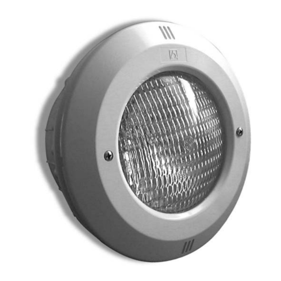
Projecteur sous-marin

Publicité

Les langues disponibles
  • FR

Les langues disponibles

  • FRANÇAIS, page 4

Liens rapides

UNTERWATER LIGHT STANDARD SERIES
PROJECTEUR SOUS-MARIN SÉRIE STANDARD
PROYECTOR SUBACUATICO SERIE STANDARD
FARO SUBACQUEO SERIA STANDARD
UNTERWASSER-SCHEINWERFER STANDARD SERIE
FARO SUBACQUEO SÉRIE STANDARD
INSTALLATION AND MAINTENANCE MANUAL
MANUEL D'INSTALLATION ET D'ENTRETIEN
MANUAL DE INSTALACIÓN Y MANTENIMIENTO
MANUALE DI INSTALAZIONE E MANUTENZIONE
EINBAU-UND BETRIEBSANLEITUNG
MANUAL DE INSTRUÇÕES E MANUNTENÇÃO

Publicité

Table des Matières
loading

Sommaire des Matières pour Astralpool STANDARD Série

  • Page 1 UNTERWATER LIGHT STANDARD SERIES PROJECTEUR SOUS-MARIN SÉRIE STANDARD PROYECTOR SUBACUATICO SERIE STANDARD FARO SUBACQUEO SERIA STANDARD UNTERWASSER-SCHEINWERFER STANDARD SERIE FARO SUBACQUEO SÉRIE STANDARD INSTALLATION AND MAINTENANCE MANUAL MANUEL D’INSTALLATION ET D’ENTRETIEN MANUAL DE INSTALACIÓN Y MANTENIMIENTO MANUALE DI INSTALAZIONE E MANUTENZIONE EINBAU-UND BETRIEBSANLEITUNG MANUAL DE INSTRUÇÕES E MANUNTENÇÃO...
  • Page 2: Important

    ENGLISH IMPORTANT: The instruction manual you are holding includes essential information on the safety measures to be implemented for installation and start-up. Therefore, the installer as well as the user must read the instructions before beginning installation and start-up. Keep this manual for future reference. To achieve optimum performance of the Standard Floodlamp follow the instructions provided below: 1.
  • Page 3: Safety Warnings

    Install the housing (no. 17) and one of the adhesive joints (no. 23) on the outer side of the pool. Install the other adhesive joint on the inner side and use two screws DIN 7981 4,8x16 (no. 22) to secure the three components. (Fig.
  • Page 4: Vérifier Le Contenu De L'emballage

    FRANÇAIS IMPORTANT: le manuel d’instructions que vous avez entre les mains contient des informations de première importance sur les mesures de sécurité à adopter au moment de l’installation et de la mise en service. Il est par conséquent indispensable que l’installateur et l’utilisateur lisent attentivement les instructions avant de commencer le montage et la mise en marche.
  • Page 5: Montage

    Pour placer un projecteur dans une piscine préfabriquée, il faut percer un trou circulaire de 240 mm de diamètre (Fig. 2). Placer la niche (num. 17) et l'un des joints adhésifs (num. 23) sur le cote extérieur de la piscine. Sur le côte intérieur, placer l'autre joint adhésif et fixer les trois éléments avec les deux vis DIN 7981 4,8x16 (num.
  • Page 6: Características Generales

    ESPAÑOL IMPORTANTE: El manual de instrucciones que usted tiene en sus manos, contiene información fundamental acerca de las medidas de seguridad a adoptar a la hora de la instalación y la puesta en servicio. Por ello, es imprescindible que tanto el instalador como el usuario lean las instrucciones antes de pasar al montaje y la puesta en marcha.
  • Page 7: Puesta En Marcha

    Colocar el nicho (nº 17) y una de las juntas adhesivas (nº 23) en el lado exterior de la piscina. En el lado interior colocar la otra junta adhesiva y fijar los tres elementos con los dos tornillos DIN 7981 4,8x16 (nº 22). (Fig. 3). Asegurarse que la salida del cable del nicho queda en la parte superior.
  • Page 8: Controllare Il Contenuto Dell'imballaggio

    ITALIANO IMPORTANTE: Il manuale d’istruzioni in suo possesso contiene informazioni fondamentali sulle misure di sicurezza da adottare per l'installazione e la messa in servizio. Per ciò è imprescindibile che sia l’installatore che l’utente leggano le istruzioni prima di iniziare il montaggio e la messa in servizio. Conservi questo manuale per poter consultare in futuro in merito al funzionamento di questo apparecchio.
  • Page 9: Messa In Servizio

    Per collocare un proiettore in una piscina prefabbricata, si deve realizzare un foro circolare di 240 mm di diámetro (Fig.2). Collocare la nicchia (n. 17) ed una delle guarnizioni adesiva (n. 23) nel lato esterno della piscina. Nel lato interno, collocare l'altra guarnizione adesiva e fissare i tre elementi con le 2 viti DIN 7981 4,8x16 (n.
  • Page 10 DEUTSCH WICHTIG: Das Handbuch mit den Betriebsanleitungen, das Sie in Händen halten, enthält wichtige Information über die anzuwendenden Sicherheitsmaßnahmen für die Installation und Inbetriebnahme. Es ist daher unerläßlich, daß die Anweisungen vom Installateur und vom Benutzer vor der Montage und Inbetriebnahme aufmerksam durchgelesen werden.
  • Page 11 Au enseite des Pools angelegt. Die andere Anhaftende Dichtung wird an die Innenseite des Pools angelegt. Diese drei Elemente werden nun mit den beiden Schrauben DIN 7981 4,8x16 (Nr. 22) (Abb. 3) befestigt, Vergewissem Sie sich, da sich der Austritt für das Kabel im oberen Teil befindet. Um die Klammer (Nr.
  • Page 12: Verifique O Conteúdo Da Embalagem

    PORTUGUÊS IMPORTANTE: O manual de instruções que você tem nas mãos contém informação fundamental sobre as medidas de segurança a tomar ao realizar a instalação e a colocação em funcionamento. Por isso, é imprescindível que tanto o instalador como o utilizador leiam as instruções antes de realizar a montagem e a colocação em funcionamento.
  • Page 13: Colocação Em Funcionamento

    Colocar o nicho (n. 17) e urna das juntas adesivas (n 23) no lado de fora da piscina. No lado de dentro, colocar a outra junta adesiva e flxar os três elementos com os dois parafusos DIN 7981 4,8 x 16 (n. 22). (Fig. 3). Assegure- se de que a salda do cabo do nicho fique situado na parte superior.
  • Page 14 ENGLISH CODE DESCRIPTION CODE DESCRIPTION 07838R0001 White decorative ring 7012306000 Nut DIN 1587 M-6 7013106080 Screw DIN 966 M-6x80 07838R0009 Gland seal joint 00347R0002 Floodlamp base fastening ring 00352R0013 Plastic washer 20x15x1,5 7010106055 DIN 933 M-6x55 screw 07838R0005 Gland seal nut 00370 PAR 56 300W 12V lamp 07838R0006...
  • Page 15 ESPAÑOL CÓDIGO DESCRIPCIÓN CÓDIGO DESCRIPCIÓN 07838R0001 Anillo embellecedor blanco 7012306000 Tuerca DIN 1587 M-6 7013106080 Tornillo DIN 966 M-6x80 07838R0009 Junta prensaestopas 00347R0002 Aro fijación fondo proyector 00352R0013 Arandela plástico 20x15x1,5 7010106055 Tornillo DIN 933 M-6x55 07838R0005 Tuerca prensaestopas 00370 Lámpara PAR 56 300W 12V 07838R0006 Nicho proyector Standard...
  • Page 16 ENGLISH CODE DESCRIPTION CODE DESCRIPTION 07838R0001 White decorative ring 00352R0013 Plastic washer 20x15x1,5 7013106080 Screw DIN 966 M-6x80 07838R0005 Gland seal nut 00347R0002 Floodlamp base fastening ring 07856R0100 Metric pitch housing ( 1) 7010106055 DIN 933 M-6x55 screw 21079R0001 Self-threading housing (2) 00370 PAR 56 300W 12V lamp 07838R0012...
  • Page 17 ESPAÑOL CÓDIGO DESCRIPCIÓN CÓDIGO DESCRIPCIÓN 07838R0001 Anillo embellecedor blanco 07838R0005 Tuerca prensaestopas 7013106080 Tornillo DIN 966 A2 M-6x80 07856R0100 Nicho con rosca métrica (1) 00347R0002 Aro fijación fondo proyector 21079R0001 Nicho autoroscante (2) 7010106055 Tornillo DIN 933 A2 M-6x55 07838R0012 Junta plana cuerpo prensaestopas 00370 Lámpara PAR 56 300W 12V...
  • Page 24 • TECHNICAL CHARACTERISTICS • CARACTERISTIQUES TECHNIQUES • CARACTERISTICAS TECNICAS • DATI TECNICI • TECHNISCHE ANGABEN • CARACTERISTICAS TECNICAS DESCRIPTION STANDARD Rated voltage / tension nominale / Tensión nominal 12 V Tensione nominale / Anschlusspannung / Tensao nominal Current suply / Type de courant / Tipo de corriente / Tipo di corrente Stromtype / Tipo de corrente Power / Pouvoir / Potencia / Potere / Macht / Poder PAR 56 12V AC 300 W...

Ce manuel est également adapté pour:

Standard série

Table des Matières