Siemens SITRANS FUS1010 Guide Rapide
Masquer les pouces
Voir aussi pour SITRANS FUS1010:
- Guide rapide (160 pages) ,
- Instructions de service (360 pages)

Manuels Connexes pour Siemens SITRANS FUS1010


Sommaire des Matières pour Siemens SITRANS FUS1010
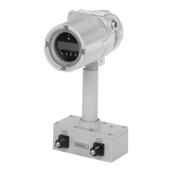
- Page 1 Ultrasonic Flowmeters SITRANS FUS1010 IP65 NEMA 7 Compact Gross Volume 7ME3531 Quick Start - 12/2008 SITRANS F...
- Page 3 Introduction Installation Commissioning SITRANS Troubleshooting/FAQs Flowmeter FUS1010 IP65 NEMA 4X Quick Start Appendix A Operating Instructions 12/2008 CQO:QSG002 Revision B...
- Page 4 Note the following: WARNING Siemens products may only be used for the applications described in the catalog and in the relevant technical documentation. If products and components from other manufacturers are used, these must be recommended or approved by Siemens. Proper transport, storage, installation, assembly, commissioning, operation and maintenance are required to ensure that the products operate safely and without any problems.
-
Page 5: Table Des Matières
Table of contents Introduction..............................5 Items supplied..........................5 Safety Notes..........................5 Installation..............................13 Application Guidelines.........................13 Mounting the Flowmeter......................13 Commissioning............................17 Connecting Power........................17 Flowmeter connection using RS-232...................19 Navigating the Menu........................21 Setting the Parameters........................23 Transducer Installation........................28 3.5.1 General information........................28 3.5.2 Installing the Transducers (Reflect Mount)..................28 3.5.3 Final Setup..........................33 Troubleshooting/FAQs..........................35 Alarm Letter Codes and Descriptions..................37 Appendix A..............................39... - Page 6 Table of contents Figures Figure 2-1 Pipe Mounting 1010 and Mounting Bracket Locations..............14 Figure 3-1 Input Power Connector (P8) Wiring.....................18 Figure 3-2 Serial Port Program Menu Screen....................19 Figure 3-3 RS-232 Interface Cable Wiring....................20 Figure 3-4 Magnetic Wand and LCD Display....................22 Figure 3-5 Reflect Mount with Mounting Frame and Spacer Bar..............29 Figure 3-6...
-
Page 7: Introduction
Introduction Intoduction This Quick Start Guide is for the Siemens SITRANS FUS1010 IP65 (NEMA 7) Dual Channel flow meters. It illustrates a typical setup using D-Series transducers in the Reflect mode (for Direct Mode see flow meter manual). These procedures can also be applied to other single and multi-channel models as well. - Page 8 The sales contract contains the entire obligation of Siemens. The warranty contained in the contact between the parties is the sole warranty of Siemens. Any statements contained herein do not create new warranties or modify the existing warranty.
- Page 9 Introduction 1.2 Safety Notes Note Ratings under this heading apply to specific model families Check Your Model Number: FUE1010 7ME3500, FUG1010, 7ME3610, FUH1010 7ME3600 and FUS1010 7ME3530 only; FM-CSA installation Read, understand and follow all safety instructions on the electronic media provided. This equipment is rated for use in hazardous (classified) locations as stated below and must be installed according to the 1010-304 installation drawing provided on the media.
- Page 10 Introduction 1.2 Safety Notes Flow Meter Markings and Explanations ● II (1) G [EEx ia] IIC – Flow meter located in the non-hazardous area with intrinsically safe circuits of category Ex ia, which can be connected to Category 1 transducers ●...
- Page 11 Introduction 1.2 Safety Notes Transducers ● Intrinsically safe connections Class I and II, Division 1, Groups A, B, C, D, E, F and G; ● Nonincendive for Class I, Division 2, Groups A, B, C and D; ● Suitable for Class II Division 2 Groups F and G outdoor (Type 4X) ●...
- Page 12 Introduction 1.2 Safety Notes Quick Start Guide Safety Information for Hazardous Areas Note Ratings under this heading apply to specific model families Check Your Model Number: FUS1010 7ME3531, FUH1010, 7ME3601, FUG1010 7ME3611 only; FM-CSA installation Read, understand and follow all safety instruction on the electronic media provided. This equipment is rated for use in hazardous (classified) locations as stated below and must be installed according to the 1010-341 installation drawing provided on the media.
- Page 13 Introduction 1.2 Safety Notes Flow Meter ● II 2 (1) G EEx d [ia] IIC T5 – Category 2 Flow meter located in Zone 1 hazardous area with intrinsically safe circuits of category Ex ia, which can be connected to Category 1 transducers for use in potentially explosive atmosphere containing gases ●...
-
Page 15: Installation
Installation Application Guidelines Basic Requirements ● Determine pipe material and dimensions. ● Avoid vertical pipes flowing in a downward direction. ● Avoid installation of transducers on the top and bottom of horizontal pipes, if possible. ● Select a location with the longest straight run of pipe. ●... - Page 16 Installation 2.2 Mounting the Flowmeter Pipe Mounting For installation on pipe use Pipe Mount Kit CQO:1012XMB-1 (optional - see catalog) See figure below. ① Clamp ④ U-Bolt Assembly for standard 2-inch (2.38in/ 6.0452cm) pipe. (Hardware supplied.) ② Mounting Bracket (Hardware not supplied for ⑤...
- Page 17 Installation 2.2 Mounting the Flowmeter Note Use conduit fittings or cable glands on all cables. Note Install weather tight seals at all unused holes using proper cable conduit and close additional holes to IP65 standards. FUS1010 IP65 NEMA 4X Quick Start Operating Instructions, 12/2008, CQO:QSG002 Revision B...
-
Page 19: Commissioning
Commissioning Connecting Power DANGER Turn off main power before installing AC connections to the flowmeter. Contact with exposed wiring may lead to fire, electric shock, or serious personal injury. 1. Using a 1/16" Hex key, loosen the flowmeter Rear Housing Cover locking setscrew. 2. - Page 20 Commissioning 3.1 Connecting Power Terminal Number 1010X-6SS2 1010X-6ZNS2 1010X-6ZPS2 Positive Positive Neutral Negative (Gnd) Negative (Gnd) Ground Ground Ground 6. Plug input power connector P8 into connector J8 and secure using two captive connector mounting screws as indicated below. 7. Secure power input cable with cable clamp to prevent wire breakage. 8.
-
Page 21: Figure 3-2 Serial Port Program Menu Screen
Commissioning 3.2 Flowmeter connection using RS-232 10. Within 10 seconds of power-up the main display will become active and an LCD display screen for use with the Magnetic Wand will appear as shown below. ① LCD panel display showing initial screen with copyright notice. Flowmeter connection using RS-232 RS-232 Connection Figure 3-2... -
Page 22: Figure 3-3 Rs-232 Interface Cable Wiring
Many newer Laptop PCs are not equipped with serial ports, having USB ports only. These PCs will require a USB RS-232 adapter that can be purchased commercially. Not all of Siemens has found the best performance is achieved with these adapters are suitable. -
Page 23: Navigating The Menu
Commissioning 3.3 Navigating the Menu Quick Terminal Mode Setup 1. Access [HyperTerminal], then select [HyperTerminal.exe]. 2. In [Connection Description] dialog box, enter a connection name (e.g. FUS1010). Click [OK]. 3. In [Phone Number] dialog box, select [Direct to COM 1 (or COM 2)]. Click [OK] to select. 4. -
Page 24: Table 3-2 Magnetic Sensor Function Chart
Commissioning 3.3 Navigating the Menu Magnetic Wand and LCD Display Panel ① 2x16 Character LCD Display Panel ⑤ Right Arrow Sensor ② Magnetic Wand ⑥ Down Arrow Sensor ③ Triggering Tip ⑦ Up Arrow Sensor ④ ENTER Sensor ⑧ Left Arrow Sensor Figure 3-4 Magnetic Wand and LCD Display Table 3-2... -
Page 25: Setting The Parameters
Commissioning 3.4 Setting the Parameters Setting the Parameters Flowmeter Programming Note Before creating a site select English or metric units from the Meter Facilities menu. Select a Meter Type 1. After power-up, use the Magnetic Wand to trigger the <ENTER> sensor and access the top level of the Installation Menu. - Page 26 Commissioning 3.4 Setting the Parameters Create a Site 1. Trigger <Right Arrow> and then <Up/Down Arrows> to select [Create/Name Site]. 2. Trigger <Right Arrow> again to select the "?" symbol (see figure below right). 3. To create site name use the <Up/Down> and <Right Arrow> to select a name. 4.
- Page 27 Commissioning 3.4 Setting the Parameters 4. Trigger <Right Arrow> sensor. Trigger <Up/Down Arrows> to scroll to select desired Pipe Size. 5. Trigger <ENTER> to save Pipe Size selection. Note Pre-programmed Pipe Size and relevant pipe parameters will appear in menu cells. To enter dimensions manually if pre-programmed dimensions do not match application, refer to FUS1010 NEMA-7 manual for details.
-
Page 28: Table 3-3 Pipe Configuration Option List Definitions
Commissioning 3.4 Setting the Parameters Select Pipe Configuration 1. Trigger <Left Arrow> and then <Down Arrow> to select [Pipe Configuration]. 2. Trigger <Right Arrow> sensor. 3. Trigger <Up/Down Arrows> to select a configuration that approximates the conditions upstream of your transducer mounting location. (Refer to the definitions below.) 4. - Page 29 Commissioning 3.4 Setting the Parameters Transducer Selection - Example for D1H High Precision Transducer 1. At the [Chan/Path Setup] menu, trigger the<Down Arrow> to select [Pick/install Xdcr]. 2. Trigger <Right Arrow> then <Down Arrow> to [Transducer Model]. 3. Trigger <Right Arrow> sensor. 4.
-
Page 30: Transducer Installation
Commissioning 3.5 Transducer Installation Note Check to make sure that the transducers are a matched set with the same serial numbers and marked with an "A" and "B" (e.g., 19256A and 19256B). Transducer Installation 3.5.1 General information Reflect and Direct Mounting Modes Reflect and Direct mounting modes are supported for clamp-on transducers. -
Page 31: Figure 3-5 Reflect Mount With Mounting Frame And Spacer Bar
Commissioning 3.5 Transducer Installation Before beginning refer to the Reflect Mount Installation diagram example below. ① Optional: On larger pipes, multiple lengths of straps ⑤ Space Bar Platform & can be linked together to surround pipe Clamping Screw ② Mounting Strap positioned around Mounting Frame ⑥... -
Page 32: Figure 3-6 Transducer Callouts
Commissioning 3.5 Transducer Installation 10.Take either transducer and apply a continuous lengthwise 1/8-inch bead of coupling compound across the center of the transducer emitting surface. ① F-Connector ② Angled Edge ③ Transducer ④ Back End ⑤ Emitting Surface ⑥ Coupling Compound Figure 3-6 Transducer Callouts 11.Slide transducer into a Mounting Frames back end first aligning the angled edge of the... -
Page 33: Figure 3-7 Transducer Installation
Commissioning 3.5 Transducer Installation ① Front View ⑥ Mounting Strap ② Spring Clip (Not present on some models) ⑦ Note: Operational 2nd Mounting Strap shown. Larger pipes may need an additional strap for a more secure mount. ③ Transducer Clamping Screw ⑧... -
Page 34: Figure 3-8 Connecting Transducers To Flowmeter
Commissioning 3.5 Transducer Installation 13. Observing the upstream and downstream orientation, attach the UP and DN cables to the transducers and make snug. Attach the other ends to the UP and DN terminals of the flowmeter (see figure below). ① Transducer Cables Connected to Flowmeter ②... -
Page 35: Final Setup
Commissioning 3.5 Transducer Installation 3.5.3 Final Setup 1. After transducers are mounted scroll to [Install Complete]. 2. Trigger <Right Arrow> sensor. 3. Trigger <Down Arrow> to select [Install]. 4. Trigger <ENTER>. 5. Observe the Measured Vs window and verify a correct sound velocity measurement (if known). - Page 36 Commissioning 3.5 Transducer Installation See also Refer to I/O Connection tables (Page 39) for input/output wiring and flowmeter manual for data spanning procedures. FUS1010 IP65 NEMA 4X Quick Start Operating Instructions, 12/2008, CQO:QSG002 Revision B...
-
Page 37: Troubleshooting/Faqs
The following is list of troubleshooting tips and messages that you may encounter. They include explanations, and in some cases, a recommended action. If a problem seems unsolvable, contact your local Siemens Ultrasonic Flow Representative for expert help (http://www.automation.siemens.com/partner). Table 4-1... - Page 38 Note If you receive a Detection Fault message, it is strongly recommended that the Technical Service Department (http://www.automation.siemens.com/partner) be contacted. FUS1010 IP65 NEMA 4X Quick Start Operating Instructions, 12/2008, CQO:QSG002 Revision B...
-
Page 39: Alarm Letter Codes And Descriptions
Troubleshooting/FAQs 4.1 Alarm Letter Codes and Descriptions Alarm Letter Codes and Descriptions Letter Code Alarm Description Spacing Transducer spacing may need readjustment. ZeroMatic ZeroMatic signal fault. Empty Pipe is empty. Rate Flow above High setting or below Low setting. Fault Three continuous seconds without new data update. -
Page 41: Appendix A
Appendix A I/O Connections and Wiring Terminal Block Wiring - 1010XS2-7 (Refer to manual drawing 1010XS2-7 sheet 3 of 3. When Barriers are used, isolation is limited to the Barrier's working voltage. Refer to table on manual drawing 1010-341 sheet 3). These connection diagrams apply to the part numbers listed below. -
Page 42: A.1 I/O Connections And Wiring
Appendix A A.1 I/O Connections and Wiring ① Flowmeter ④ User 4-20mA Source ② Barrier ⑤ To TB2-16 Gnd ③ User Supply +24V ⑥ Output Vc Isolated 4-20mA Output TB1-1/3 & TB1-2/4 R = 1000 ohms (max) w/o Barriers R = 320 ohms (max) with Barriers Vc = Output High and Low I = 4-20mA R = Loop wire resistance (both ways) plus User's input load resistance. - Page 43 Appendix A A.1 I/O Connections and Wiring Table A-3 FUS1010X Input/Output Wiring (TB2) Pin# Signal Function Description RS-232 Transmit Standard Standard RS-232 RS-232 Signals Communication Port RS-232 Request to Send RS-232 Data Terminal Ready RS-232 Receive RS-232 Clear to Send Ground D1 Input Digital Input CH.1...
- Page 44 Appendix A A.1 I/O Connections and Wiring Terminal Block Wiring - 1010DXS2-7 (Refer to manual drawing 1010DXS2-7 sheet 3 of 4. When Barriers are used, isolation is limited to the Barrier's working voltage. Refer to table on manual drawing 1010-341 sheet 3). These connection diagrams apply to the part numbers listed below.
-
Page 45: A.2 Technical Data
Appendix A A.2 Technical Data Table A-6 FUS1010DX Input/Output Wiring (TB2) Pin# Signal Function Description RS-232 Transmit Standard Standard RS-232 RS-232 Signals Communication Port RS-232 Request to Send RS-232 Data Terminal Ready RS-232 Receive RS-232 Clear to Send Ground D1 Input Digital Input Ch.1 Isolated Digital Freeze Totalizer Ch.1... - Page 47 Diagnostic Data Flow Data Enter From List Application Info Enter From List Liquid Data Enter From List Siemens Industry, Inc. Site Setup Data Enter From List Industry Automation Division Test Facilities Enter From List CoC Ultrasonic Flow Print Site Setup...
- Page 48 FUS1010 IP65 (NEMA 7) Installation Menu Chart LEVEL A LEVEL B LEVEL C/D LEVEL E (see manual) LEVEL F LEVEL G Meter Facilities Preferred Units English/Metric Table Setups Pipe Table Create/Edit Pipe Enter From List Delete Pipe Enter From List Transducer Type Enter From List Datalogger Control...
- Page 49 Sicherheitshinweise Einleitung Anschließen SITRANS Betrieb (Hardware) Durchflussmessgerät Alarm-, Fehler- und SITRANS FUS1010 NEMA-7 Systemmeldungen Quick Start Guide Fehlerbehebung/FAQs Betriebsanleitung Anhang 08/2008 CQO:QSG002 Revison B...
- Page 50 Siemens-Produkte dürfen nur für die im Katalog und in der zugehörigen technischen Dokumentation vorgesehenen Einsatzfälle verwendet werden. Falls Fremdprodukte und -komponenten zum Einsatz kommen, müssen diese von Siemens empfohlen bzw. zugelassen sein. Der einwandfreie und sichere Betrieb der Produkte setzt sachgemäßen Transport, sachgemäße Lagerung, Aufstellung, Montage, Installation, Inbetriebnahme, Bedienung und Instandhaltung voraus.
- Page 51 Teilenummern und Anschlusspläne.....................41 Tabelle A- 2 FUS1010X-Eingangs-/Ausgangsverdrahtung (TB1)..............41 Tabelle A- 3 FUS1010X-Eingangs-/Ausgangsverdrahtung (TB2)..............43 Tabelle A- 4 Teilenummern und Anschlusspläne.....................45 Tabelle A- 5 FUS1010DX-Eingangs-/Ausgangsverdrahtung (TB1)..............45 Tabelle A- 6 FUS1010DX-Eingangs-/Ausgangsverdrahtung (TB2)..............46 SITRANS FUS1010 NEMA-7 Quick Start Guide Betriebsanleitung, 08/2008, CQO:QSG002 Revision B...
- Page 52 Bild 4-1 Reflekt-Montage mit Montagerahmen und Abstandshalter ............29 Bild 4-2 Transducer - Abbildungslegende ....................30 Bild 4-3 Transducer-Installation........................ 31 Bild 4-4 Anschließen der Transducer an den Durchflussanzeigerechner..........32 SITRANS FUS1010 NEMA-7 Quick Start Guide Betriebsanleitung, 08/2008, CQO:QSG002 Revision B...
-
Page 53: Sicherheitshinweise
Sachschaden zur Folge. • Beachten Sie die Anweisungen zur Installation. • Trennen Sie das Betriebsmittel vor Servicearbeiten von der Spannungsquelle. • Halten Sie während des Betriebs des Betriebsmittels die Gehäuseabdeckung geschlossen. SITRANS FUS1010 NEMA-7 Quick Start Guide Betriebsanleitung, 08/2008, CQO:QSG002 Revision B... - Page 54 Verpflichtungen von Siemens ergeben sich aus dem jeweiligen Kaufvertrag. Die Gewährleistung aus dem Vertrag zwischen den Vertragsparteien stellt die einzig gültige Gewährleistung von Siemens dar. Durch die Ausführungen dieses Quick Start Guide werden weder neue Gewährleistungsbestimmungen geschaffen noch bestehende geändert.
- Page 55 Bereich Zone 2 befindet, mit eigensicheren Stromkreisen der Kategorie Ex ia, anschließbar an Transducer der Kategorie 1 in Zone 0. ● IP65 – Schutz gegen Eindringen fester Fremdkörper, staub- und flüssigkeitsdicht, Schutz gegen Strahlwasser. SITRANS FUS1010 NEMA-7 Quick Start Guide Betriebsanleitung, 08/2008, CQO:QSG002 Revision B...
- Page 56 ● Nicht-zündgefährlich für Class I, Division 2, Groups A, B, C und D; ● Geeignet für Class II Division 2 Groups F und G Outdoor-Bereich (Type 4X) ● Temperaturcode T5 bei Umgebungstemperatur 40 °C SITRANS FUS1010 NEMA-7 Quick Start Guide Betriebsanleitung, 08/2008, CQO:QSG002 Revision B...
- Page 57 Bereichen Zone 1 befinden, mit eigensicheren Stromkreisen der Kategorie Ex ia, zum Einsatz in potenziell explosionsgefährdeter, gashaltiger Atmosphäre. ● IP65 – Schutz gegen Eindringen fester Fremdkörper, staub- und flüssigkeitsdicht, Schutz gegen Strahlwasser. SITRANS FUS1010 NEMA-7 Quick Start Guide Betriebsanleitung, 08/2008, CQO:QSG002 Revision B...
- Page 58 Betriebsmittel vorgeschriebenen Installationsschritte führt zu unsicheren Betriebszuständen. Beachten Sie beim Betrieb dieses Betriebsmittels alle regionalen gesetzlichen Sicherheitsvorschriften. Bei ordnungsgemäßer Installation erfüllt dieses Betriebsmittel die folgenden ATEX-Kriterien laut EG-Baumusterprüfbescheinigung KEMA03ATEX2133: SITRANS FUS1010 NEMA-7 Quick Start Guide Betriebsanleitung, 08/2008, CQO:QSG002 Revision B...
- Page 59 Bereichen Zone 1 befinden, mit eigensicheren Stromkreisen der Kategorie Ex ia, zum Einsatz in potenziell explosionsgefährdeter, gashaltiger Atmosphäre. ● IP65 – Schutz gegen Eindringen fester Fremdkörper, staub- und flüssigkeitsdicht, Schutz gegen Strahlwasser. SITRANS FUS1010 NEMA-7 Quick Start Guide Betriebsanleitung, 08/2008, CQO:QSG002 Revision B...
-
Page 61: Einleitung
Einleitung Der vorliegende Quick Start Guide behandelt die Zweikanal-Durchflussmessgeräte SITRANS FUS1010 IP65 (NEMA 7) von Siemens. Es wird eine typische Installation und Konfiguration unter Verwendung von Transducern der D-Serie im Reflekt- und Direkt-Modus dargestellt (Informationen zum Direkt-Modus enthält das Handbuch zum Durchflussmessgerät). -
Page 62: Bild
(Montagematerial im Lieferumfang enthalten.) ② Befestigungsflansch (Montagematerial für ⑤ Eingangsbuchsen für Transducerkabel Wandmontage nicht im Lieferumfang). ③ Rohr ⑥ Kunststoffstreifen unter Klemmschelle legen Bild 2-1 Montagestellen für Rohrmontage und Befestigungsflansch SITRANS FUS1010 NEMA-7 Quick Start Guide Betriebsanleitung, 08/2008, CQO:QSG002 Revision B... -
Page 63: Menüaufbau Und -Navigation
Ebene C - enthält Auswahldaten für Ebene B. Ebene A Ebene B Ebene C Messortkonfiguration abrufen Pumpe 1 Pumpe 2 Kanal aktivieren Anl/Name Messort Messortsicherh. Messortkonfiguration loeschen Ort sp./umbenenn SITRANS FUS1010 NEMA-7 Quick Start Guide Betriebsanleitung, 08/2008, CQO:QSG002 Revision B... -
Page 64: Tabelle 2- 1 Funktionsübersicht Magnetstift
Entsprechend Links- und Rechtspfeil. Zum Blättern in Optionslisten und der Grafik-Anzeige. Typische Anzeige des Installationsmenüs - Beispiel ① Oberste Ebene des Installationsmenüs ③ Anwahlsymbol ENTER ② ENTER-Schalter ④ Aktuelle Auswahl SITRANS FUS1010 NEMA-7 Quick Start Guide Betriebsanleitung, 08/2008, CQO:QSG002 Revision B... -
Page 65: Anschließen
90-250 V Wechselstrom, einphasig 1010X-6ZNS2 9-36 V Gleichstrom, negative Erde 1010X-6ZPS2 9-36 V Gleichstrom, positive Erde Hinweis Das Produktnummern-Schild des Netzteils befindet sich an der Innenseite der vorderen Gehäuseabdeckung. SITRANS FUS1010 NEMA-7 Quick Start Guide Betriebsanleitung, 08/2008, CQO:QSG002 Revision B... - Page 66 Tabellen ermittelt haben (100-250 V Wechselstrom mit 50/60 Hz oder 9-36 V Gleichstrom), und schalten Sie das Gerät ein. Hinweis Drahtklemmschraube lösen, abisoliertes Drahtende einführen und Schraube erneut anziehen. SITRANS FUS1010 NEMA-7 Quick Start Guide Betriebsanleitung, 08/2008, CQO:QSG002 Revision B...
-
Page 67: Tabelle 3- 1 Farbkennzeichnung
● Innerhalb von zehn Sekunden nach dem Einschalten wird die Hauptanzeige des Durchflussanzeigerechners aktiviert, und ein mit dem Magnetstift bedienbares LCD- Anzeigefeld erscheint wie unten abgebildet. ① LCD-Anzeigefeld mit Eingangsbildschirm (Copyrightvermerk) SITRANS FUS1010 NEMA-7 Quick Start Guide Betriebsanleitung, 08/2008, CQO:QSG002 Revision B... -
Page 68: Bild
Sie je nach Bauart des Anschlusses entweder den 9-oder den 25-poligen Stecker oder einen USB-RS-232-Adapter verwenden. ● Näheres zum Aufrufen des Installationsmenüs finden Sie im Handbuch für den FUS1010- Durchflussanzeigerechner. SITRANS FUS1010 NEMA-7 Quick Start Guide Betriebsanleitung, 08/2008, CQO:QSG002 Revision B... -
Page 69: Bild
6. Öffnen Sie das Register [Einstellungen]. Wählen Sie im Feld [Emulation] den Eintrag [VT- 100]. 7. Wählen Sie [ASCII-Konfiguration]. Entfernen Sie unter [Einstellungen für den ASCII- Versand] die Markierungen der Kontrollkästchen. Markieren Sie unter [Einstellungen für SITRANS FUS1010 NEMA-7 Quick Start Guide Betriebsanleitung, 08/2008, CQO:QSG002 Revision B... - Page 70 Klicken Sie auf [OK]. 8. Geben Sie im Terminal-Bildschirm ein: Menu. Drücken Sie <ENTER>, um das Installationsmenü aufzurufen. Tipp: Geben Sie ein: Menu 1000, um eine längere Verbindungszeit einzustellen. SITRANS FUS1010 NEMA-7 Quick Start Guide Betriebsanleitung, 08/2008, CQO:QSG002 Revision B...
-
Page 71: Betrieb (Hardware)
● Wählen Sie durch Betätigen des <ENTER>-Sensors den Modus aus. Das Menü [Einst. Kanal] wird angezeigt. ① Oberste Ebene ③ Sensor für Anwahlsymbol ENTER Installationsmenü ② ENTER-Sensor ④ Aktuelle Auswahl Hinweis WICHTIG: Neben einem angewählten Menüeintrag erscheint ein Doppelpunkt. SITRANS FUS1010 NEMA-7 Quick Start Guide Betriebsanleitung, 08/2008, CQO:QSG002 Revision B... - Page 72 ● Betätigen Sie den <Rechtspfeil>, um [Auswahl Rohrklasse] auszuwählen. ● Betätigen Sie erneut den <Rechtspfeil>. Blättern Sie durch Betätigen des <Aufwärts- /Abwärtspfeils> zur gewünschten Rohrklasse. ● Wählen Sie die Rohrklasse durch Betätigen von <ENTER>. SITRANS FUS1010 NEMA-7 Quick Start Guide Betriebsanleitung, 08/2008, CQO:QSG002 Revision B...
- Page 73 ● Blättern Sie durch Betätigen des <Aufwärts-/Abwärtspfeils> zur gewünschten Flüssigkeit. ● Speichern Sie die Auswahl durch Betätigen von <ENTER>. ① Doppelpunkt wird angezeigt ② Neue Flüssigkeit aus der Liste auswählen SITRANS FUS1010 NEMA-7 Quick Start Guide Betriebsanleitung, 08/2008, CQO:QSG002 Revision B...
-
Page 74: Tabelle 4- 1 Definitionen Für Die Optionsliste Zur Rohranordnung
Doppelrohrbogen in zwei Ebenen stromaufwärts von der Transducer-Montagestelle. Dppl-Rohrbogen- Doppelrohrbogen in einer Ebene stromaufwärts von der Transducer-Montagestelle. Ventil Derzeit nicht verfügbar. Rohrerweiterung Rohrerweiterung stromaufwärts von der Transducer- Montagestelle. Rohrverengung Rohrverengung stromaufwärts von der Transducer- Montagestelle. SITRANS FUS1010 NEMA-7 Quick Start Guide Betriebsanleitung, 08/2008, CQO:QSG002 Revision B... - Page 75 <Abwärtspfeil>, um Daten zu ermitteln. ● Die Transducer können jetzt montiert werden. ① Hier den Transducer-Typ auswählen. ② Hier die Transducer-Größe auswählen. ③ Nach erfolgter Montage des Transducers [Installation] wählen. SITRANS FUS1010 NEMA-7 Quick Start Guide Betriebsanleitung, 08/2008, CQO:QSG002 Revision B...
-
Page 76: Transducer-Installation
Montagezubehör Zur Montage der Transducer wird folgendes Material und Werkzeug benötigt: ● Flacher Schraubendreher ● Montagerahmen oder Montageschienen ● Klebeband, Kreide und Lineal oder Maßband ● Metallmontagebänder ● Abstandshalter SITRANS FUS1010 NEMA-7 Quick Start Guide Betriebsanleitung, 08/2008, CQO:QSG002 Revision B... -
Page 77: Bild
Sie die Bohrung für den Nummernindex am Anschlagstift der Klemme aus. Vergewissern Sie sich, dass die Ziehen Sie anschließend die Befestigungsschraube an. abgeschrägten Seiten der beiden Montagerahmen jeweils nach außen zeigen. SITRANS FUS1010 NEMA-7 Quick Start Guide Betriebsanleitung, 08/2008, CQO:QSG002 Revision B... -
Page 78: Bild
Anschlag des Montagerahmens erreicht hat. 12. Ziehen Sie die Befestigungsschraube des Transducers so weit an, dass der Transducer Wiederholen Sie diese Installationsschritte mit dem in seiner Position gehalten wird. anderen Transducer SITRANS FUS1010 NEMA-7 Quick Start Guide Betriebsanleitung, 08/2008, CQO:QSG002 Revision B... - Page 79 Kennzeichnungen UP (aufwärts) und DN (abwärts) an den Transducern, und ziehen Sie die Kabel fest. Befestigen Sie die anderen Enden der Kabel an den UP- und DN-Eingängen des Durchflussanzeigerechners (s. folgende Abbildung). SITRANS FUS1010 NEMA-7 Quick Start Guide Betriebsanleitung, 08/2008, CQO:QSG002 Revision B...
-
Page 80: Bild
Abschluss der Installation des Durchflussmessgeräts ● Blättern Sie nach der Montage der Transducer zu [Install. beendet]. ● Betätigen Sie den <Rechtspfeil>-Sensor. ● Betätigen Sie den <Abwärtspfeil>, um [Installation] auszuwählen. ● Betätigen Sie <ENTER>. SITRANS FUS1010 NEMA-7 Quick Start Guide Betriebsanleitung, 08/2008, CQO:QSG002 Revision B... - Page 81 Schallgeschwindigkeit, und prüfen Sie die Angabe auf Richtigkeit (falls korrekte Geschwindigkeit bekannt). ● Falls korrekt, betätigen Sie den <Abwärtspfeil>. ● Das Durchflussmessgerät ist jetzt betriebsbereit für die Durchflussmessung. ① Wählen Sie [Installation] aus. SITRANS FUS1010 NEMA-7 Quick Start Guide Betriebsanleitung, 08/2008, CQO:QSG002 Revision B...
-
Page 83: Alarm-, Fehler- Und Systemmeldungen
Gemessene Ultraschallgeschwindigkeit der Flüssigkeit überschreitet Alarm- Sollwert für die Trennschicht. Molchmeld. Durchfahrt von Molch erkannt (Option). Die folgende Abbildung zeigt, an welcher Stelle des LCD-Anzeigefelds die Alarmmeldungen erscheinen. ① Alarmcodes SITRANS FUS1010 NEMA-7 Quick Start Guide Betriebsanleitung, 08/2008, CQO:QSG002 Revision B... -
Page 85: Fehlerbehebung/Faqs
Hinweisen zur jeweiligen Meldung. Die Hinweise umfassen Erläuterungen und z. T. auch empfohlene Maßnahmen zur Fehlerbehebung. Erscheint dennoch ein Problem einmal unlösbar, setzen Sie sich mit den Experten der nächsten Siemens-Vertretung für den Bereich Ultraschall-Durchflussmessung in Verbindung (www.automation.siemens.com/partner). Tabelle 6- 1 Tipps zur Fehlerbehebung... - Page 86 Betätigen Sie <ENTER>, <Aufwärtspfeil>, • <Abwärtspfeil> oder <Linkspfeil>, um die Installationsroutine abzubrechen. Programmieren Sie erst die anderen Messortdaten. Das Problem lässt sich möglicherweise später lösen. Bei Bedarf verständigen Sie unseren Technischen Service. SITRANS FUS1010 NEMA-7 Quick Start Guide Betriebsanleitung, 08/2008, CQO:QSG002 Revision B...
- Page 87 Schallleitfähigkeit der Rohrwand oder der Flüssigkeit oder durch übermäßige Luftblasenbildung verhindert wird. Hinweis Erscheint die Meldung "Erkennung Fehler", empfehlen wir Ihnen, sich von unserem Technischen Service beraten zu lassen. SITRANS FUS1010 NEMA-7 Quick Start Guide Betriebsanleitung, 08/2008, CQO:QSG002 Revision B...
-
Page 89: Anhang
über Menüauswahl zugewiesener Io1 + Vorlauf über isolierten Datenvariablen Stromkreis ANIN - Analogeingang Rücklauf 4-20 mA-Eingang, nicht isoliert (nur 7ME3531- ANIN + 4-20 mA-Eingang Status - Statusbit Rücklauf Status-Alarm, isoliert (Emitter) SITRANS FUS1010 NEMA-7 Quick Start Guide Betriebsanleitung, 08/2008, CQO:QSG002 Revision B... - Page 90 Bei Verwendung von Barrieren + 12 V Gleichstrom nicht überschreiten. Polarität NICHT umkehren. Last: 200 Ohm ohne Barriere plus Leitungswiderstand (beide Richtungen) 320 Ohm ohne Barriere plus Leitungswiderstand (beide Richtungen) SITRANS FUS1010 NEMA-7 Quick Start Guide Betriebsanleitung, 08/2008, CQO:QSG002 Revision B...
-
Page 91: Tabelle A- 3 Fus1010X-Eingangs-/Ausgangsverdrahtung (Tb2)
(Bereit zum Senden) Masse D1-Eingang Digitaleingang Kan.1 Isolierte Zähler anhalten Kan. 1 digitale D1-Rücklauf Digitaler Rücklauf Rücklauf Befehlsleitunge D2-Eingang Digitaleingang Kan. 2 Zähler zurücksetzen Kan. 2 D2-Rücklauf Digitaler Rücklauf Rücklauf SITRANS FUS1010 NEMA-7 Quick Start Guide Betriebsanleitung, 08/2008, CQO:QSG002 Revision B... - Page 92 Barrieren ist die Isolierung auf die Arbeitsspannung der Barriere begrenzt. Siehe die Tabelle in der Zeichnung 1010-341, Blatt 3, im Handbuch.) Die folgenden Anschlusspläne beziehen sich auf die Teilenummern wie nachstehend aufgeführt: SITRANS FUS1010 NEMA-7 Quick Start Guide Betriebsanleitung, 08/2008, CQO:QSG002 Revision B...
-
Page 93: Tabelle A- 4 Teilenummern Und Anschlusspläne
Status-Alarm (Kollektor), Kan. 1 Status -2 Statusbit Rücklauf Status-Alarm (Emitter), Kan. 2 Status +2 Status-Ausgang Status-Alarm (Kollektor), Kan. 2 Hinweis Verdrahtungsplan für FUS1010DX TB2 ist inhaltsgleich mit Tabelle A-2. SITRANS FUS1010 NEMA-7 Quick Start Guide Betriebsanleitung, 08/2008, CQO:QSG002 Revision B... -
Page 94: Tabelle A- 6 Fus1010Dx-Eingangs-/Ausgangsverdrahtung (Tb2)
Digitaler Rücklauf Rücklauf Technische Daten Temperaturbereich Schutzart Betrieb: -10 C bis 50 C (14 F bis 122 IP65 NEMA 7 Lagerung: -20 C bis 60 C (-4 F bis 140 SITRANS FUS1010 NEMA-7 Quick Start Guide Betriebsanleitung, 08/2008, CQO:QSG002 Revision B... - Page 95 Eingabe aus Liste MLFB - 7ME3531 Loggerereignisse Eingabe aus Liste 7ME3532 E/A Datenkontr. Einstellg. AA Eingabe aus Liste Relaiseinstellg. Relais 1,2 Einstellg. AE Eingabe aus Liste Siemens Industry, Inc. Industry Automation Division CoC Ultrasonic Flow Hauppauge, New York Web: www.usa.siemens.com...
- Page 96 Übersicht Installtionsmenü FUS1010 IP65 (NEMA 7) BENE A EBENE B EBENE C/D EBENE E (s Handbuch) EBENE F EBENE G Diagnosedaten D. flussdaten Eingabe aus Liste Anwendungs Info Eingabe aus Liste Fluessig.daten Eingabe aus Liste Ortskonf.daten Eingabe aus Liste Testeinrichtung Eingabe aus Liste Ortskonf.
- Page 97 Introduction Installation Mise en service SITRANS Diagnostic d'erreurs/FAQ Débitmètre Guide de mise en route rapide Annexe A SITRANS FUS1010 Instructions de service 2/2009 CQO:QSG:002 Revision B...
- Page 98 Tenez compte des points suivants: ATTENTION Les produits Siemens ne doivent être utilisés que pour les cas d'application prévus dans le catalogue et dans la documentation technique correspondante. S'ils sont utilisés en liaison avec des produits et composants d'autres marques, ceux-ci doivent être recommandés ou agréés par Siemens. Le fonctionnement correct et sûr des produits suppose un transport, un entreposage, une mise en place, un montage, une mise en service, une utilisation et une maintenance dans les règles de l'art.
- Page 99 Câblage des entrées/sortie FUS1010X (TB2)................43 Tableau A-4 Numéros de référence et schémas de connexion...............44 Tableau A-5 Câblage des entrées/sortie FUS1010DX (TB1)................44 Tableau A-6 Câblage des entrées/sortie FUS1010DX (TB2)................45 Guide de mise en route rapide SITRANS FUS1010 Instructions de service, 2/2009, CQO:QSG:002 Revision B...
- Page 100 Figure 3-5 Montage réflexion avec châssis de montage et entretoise............30 Figure 3-6 Légende du capteur........................31 Figure 3-7 Installation capteur........................32 Figure 3-8 Connexion des capteurs au débitmètre..................34 Guide de mise en route rapide SITRANS FUS1010 Instructions de service, 2/2009, CQO:QSG:002 Revision B...
-
Page 101: Introduction
Le présent guide de mise en route est destiné aux débitmètres à deux voies SITRANS FUS1010 IP65 (NEMA 7) de Siemens. Il illustre une configuration type utilisant des capteurs de série D en mode réflexion (pour le mode direct, référez-vous au manuel du débitmètre). - Page 102 Siemens. La garantie contenue dans le contrat entres les parties constitue l'unique garantie de Siemens. Aucune déclaration ici faite ne peut entraîner la création de nouvelles garanties ou la modification de garanties déjà existantes.
- Page 103 équipement. Lorsqu'il est installé correctement, cet équipement répond aux caractéristiques ATEX suivantes, stipulées dans le certificat d'inspection CE KEMA03ATEX1134. Guide de mise en route rapide SITRANS FUS1010 Instructions de service, 2/2009, CQO:QSG:002 Revision B...
- Page 104 ● Anti-flambée de poussière pour la classe II, division 1, groupes E, F et G ● Connexions à sécurité intrinsèque pour les classes I et II, division 1, groupes A, B, C, D, E, F et G ; Guide de mise en route rapide SITRANS FUS1010 Instructions de service, 2/2009, CQO:QSG:002 Revision B...
- Page 105 ● IP66 – Protection contre toute pénétration de corps solides, dimensionnement étanche aux poussières et aux liquides, même en cas de grosse mer Guide de mise en route rapide SITRANS FUS1010 Instructions de service, 2/2009, CQO:QSG:002 Revision B...
- Page 106 ● Appropriés à la classe II, division 2, groupes F et G en extérieur (type 4X) ● Code de température T5 pour un air ambiant de 40°C Guide de mise en route rapide SITRANS FUS1010 Instructions de service, 2/2009, CQO:QSG:002 Revision B...
- Page 107 ● IP65 – Protection contre toute pénétration de corps solides, dimensionnement étanche aux poussières et aux liquides, de même qu'aux jets d'eau Guide de mise en route rapide SITRANS FUS1010 Instructions de service, 2/2009, CQO:QSG:002 Revision B...
-
Page 109: Installation
Le débitmètre peut être monté sur n'importe quelle surface en bois, métal ou béton. Utilisez les écrous et vis adéquats à votre type de montage (voir la figure ci-après pour le positionnement des supports de fixation). Guide de mise en route rapide SITRANS FUS1010 Instructions de service, 2/2009, CQO:QSG:002 Revision B... -
Page 110: Figure 2-1 Montage De La Conduite 1010 Et Montage Des Supports De Fixation
③ Conduite ⑥ Positionnement du feuillard en plastique sous l'étrier Figure 2-1 Montage de la conduite 1010 et montage des supports de fixation Guide de mise en route rapide SITRANS FUS1010 Instructions de service, 2/2009, CQO:QSG:002 Revision B... - Page 111 Installez des joins étanches aux intempéries sur tous les orifices non utilisés en vous servant d'un conduit de câbles adéquat et obturez les orifices supplémentaires conformément aux normes IP65. Guide de mise en route rapide SITRANS FUS1010 Instructions de service, 2/2009, CQO:QSG:002 Revision B...
-
Page 113: Mise En Service
1010X-6ZPS2 9-36 V CC, prise de masse de polarité positive Remarque L'étiquette du module d'alimentation P/N est placée à l'intérieur du couvercle avant du boîtier. Guide de mise en route rapide SITRANS FUS1010 Instructions de service, 2/2009, CQO:QSG:002 Revision B... -
Page 114: Figure 3-1 Câblage Du Connecteur D'alimentation (P8)
Desserrez la vis serre-fil, introduisez l'extrémité dénudée du fil, puis resserrez. ① Vis serre-fil ② Vis de montage du connecteur ③ Fil dénudé Figure 3-1 Câblage du connecteur d'alimentation (P8) Guide de mise en route rapide SITRANS FUS1010 Instructions de service, 2/2009, CQO:QSG:002 Revision B... -
Page 115: Connexion Du Débitmètre Via Rs-232
Pour utiliser l'interface RS-232 au lieu de l'écran principal de l'unité afin de programmer le débitmètre, vous devez posséder des connaissance fondamentales dans la programmation Guide de mise en route rapide SITRANS FUS1010 Instructions de service, 2/2009, CQO:QSG:002 Revision B... - Page 116 TB2. Notez que la broche CTS des deux connecteurs est court- circuitée avec la broche RTS (broches 4-5 du connecteur à 25 broches et broches 7-8 du connecteur à 9 broches). Guide de mise en route rapide SITRANS FUS1010 Instructions de service, 2/2009, CQO:QSG:002 Revision B...
-
Page 117: Navigation Dans Le Menu
Niveau B - liste des champs de menus associés au niveau A. Vous pouvez saisir des données dans les champs de menus de niveau B Niveau C - liste des données du niveau B Guide de mise en route rapide SITRANS FUS1010 Instructions de service, 2/2009, CQO:QSG:002 Revision B... - Page 118 Déplacement du curseur au moyen des touches de navigation du menu. Flèches haut / bas Identiques aux flèches <Gauche> et <Droite>. Défilement dans les listes d'options et l'écran graphique. Guide de mise en route rapide SITRANS FUS1010 Instructions de service, 2/2009, CQO:QSG:002 Revision B...
-
Page 119: Configuration Des Paramètres
4. Activez le capteur <ENTREE> pour sélectionner le type d'appareil de mesure : [Clamp-on voie 1] s'affiche. Guide de mise en route rapide SITRANS FUS1010 Instructions de service, 2/2009, CQO:QSG:002 Revision B... - Page 120 2. Activez un nouvelle fois <Flèche droite> pour sélectionner le symbole "?" (voir figure de droite ci-après). 3. Pour créer le nom du site, servez-vous de <Flèche haut/bas> et <Flèche droite> pour sélectionner un nom. Guide de mise en route rapide SITRANS FUS1010 Instructions de service, 2/2009, CQO:QSG:002 Revision B...
- Page 121 2. Activez une nouvelle fois <Flèche droite>. Activez <Flèche haut/bas> pour défiler jusqu'au type de conduite souhaité. 3. Activez <ENTREE> pour sélectionner le type de conduite. Guide de mise en route rapide SITRANS FUS1010 Instructions de service, 2/2009, CQO:QSG:002 Revision B...
- Page 122 4. Activez <Flèche haut/bas> pour défiler jusqu'au liquide souhaité. 5. Activez <ENTREE> pour enregistrer la sélection. ① Un double point s'affiche. ② Sélectionnez un nouveau liquide dans la liste. Guide de mise en route rapide SITRANS FUS1010 Instructions de service, 2/2009, CQO:QSG:002 Revision B...
- Page 123 Réduction de conduite en amont de l'installation du capteur. Entree normale Non disponible à l'heure actuelle. Entree collect Collecteur en amont de l'installation du capteur. Intrusions Non disponible à l'heure actuelle. Guide de mise en route rapide SITRANS FUS1010 Instructions de service, 2/2009, CQO:QSG:002 Revision B...
- Page 124 Numéro de référence : 1011HNFS-D1HUT1-S2 indique : Par exemple, le ① Modèle ⑤ Agrément ② Haute précision ⑥ Température ③ NEMA w/F-Conn ⑦ Taille ④ Matériau conduite Guide de mise en route rapide SITRANS FUS1010 Instructions de service, 2/2009, CQO:QSG:002 Revision B...
-
Page 125: Installation Capteur
● Ruban, craie et règle ou mètre à ruban ● Courroies de montage ● Entretoise ● Guide de montage (pour le montage direct) ● Pâte adhérente ultrasonique ● Capteurs (adaptés l'un à l'autre) Guide de mise en route rapide SITRANS FUS1010 Instructions de service, 2/2009, CQO:QSG:002 Revision B... -
Page 126: Installation Des Capteurs (Montage Réflexion)
3. Entourez la conduite d'une courroie de montage. Veillez à ce que la vis de réglage de la courroie reste aisément accessible. 4. Placez le châssis avec l'entretoise sur la partie supérieure de la conduite. Guide de mise en route rapide SITRANS FUS1010 Instructions de service, 2/2009, CQO:QSG:002 Revision B... -
Page 127: Figure 3-6 Légende Du Capteur
Procédez de la même 12.Serrez la vis de serrage du capteur afin de le maintenir en place. manière avec l'autre capteur . Guide de mise en route rapide SITRANS FUS1010 Instructions de service, 2/2009, CQO:QSG:002 Revision B... -
Page 128: Figure 3-7 Installation Capteur
Orientation pour capteur à rayon unique en position 9 heures ⑪ Orientation pour capteur à rayons doubles en position 10 heures et 2 heures Figure 3-7 Installation capteur Guide de mise en route rapide SITRANS FUS1010 Instructions de service, 2/2009, CQO:QSG:002 Revision B... - Page 129 13. Branchez les câbles UP et DN aux capteurs en respectant l'orientation amont et aval et serrez-les. Branchez les autres extrémités aux bornes UP et DN du débitmètre (voir figure ci-après). Guide de mise en route rapide SITRANS FUS1010 Instructions de service, 2/2009, CQO:QSG:002 Revision B...
-
Page 130: Configuration Finale
1. Une fois le montage des capteurs effectué, défilez jusqu'à [Installt. OK]. 2. Activez le capteur <Flèche droite>. 3. Activez <Flèche bas> pour sélectionner [Installer]. Guide de mise en route rapide SITRANS FUS1010 Instructions de service, 2/2009, CQO:QSG:002 Revision B... - Page 131 Référez-vous aux tableaux des connexions E/S (Page 41) pour le câblage des entrées/ sorties et au manuel du débitmètre pour les procédures de détermination des données. Guide de mise en route rapide SITRANS FUS1010 Instructions de service, 2/2009, CQO:QSG:002 Revision B...
-
Page 133: Diagnostic D'erreurs/Faq
Vous trouverez ci-après la liste des conseils et messages d'éventuels diagnostics d'erreur. Ils fournissent des applications et, le cas échant, l'action recommandée. Si vous êtes face à un problème que vous ne savez résoudre, contactez votre agence locale Siemens Ultrasonic Flow pour obtenir l'aide de nos experts (http://www.automation.siemens.com/partner). - Page 134 <Flèche gauche> pour annuler la routine d'installation. Poursuivez la programmation des autres données du site en attendant de résoudre ce problème ultérieurement. Si nécessaire, contactez notre assistance technique. Guide de mise en route rapide SITRANS FUS1010 Instructions de service, 2/2009, CQO:QSG:002 Revision B...
-
Page 135: Codes Et Descriptions Des Alarmes
La conduite est vide. Taux Le débit se situe au-delà des limites maximum ou minimum. Défaut Pas de rafraîchissement des données pendant trois secondes successives Guide de mise en route rapide SITRANS FUS1010 Instructions de service, 2/2009, CQO:QSG:002 Revision B... - Page 136 La valeur Vs du liquide dépasse la limite d'alarme pour l'interface. Ramoneur Ramoneur détecté (optionnel). L'écran représenté ci-après indique où les codes d'alarme s'affichent sur l'écran LCD. ① Codes d'alarmes Guide de mise en route rapide SITRANS FUS1010 Instructions de service, 2/2009, CQO:QSG:002 Revision B...
- Page 137 ANIN + Entrée 4-20 mA Etat - Retour par bit d'état Emetteur d'alarme d'état isolé Etat + Sortie d'état Collecteur d'alarme d'état isolé Guide de mise en route rapide SITRANS FUS1010 Instructions de service, 2/2009, CQO:QSG:002 Revision B...
-
Page 138: A.1 Connexions Et Câblage Des Entrées/Sorties
I = 7 mA (max.) Rc = charge totale non inductive Niveau haut et bas sortie Vc pour différentes VC avec : R = 4,7 kilo-ohms, 0,15 Watt (min.) Guide de mise en route rapide SITRANS FUS1010 Instructions de service, 2/2009, CQO:QSG:002 Revision B... -
Page 139: Tableau A-3 Câblage Des Entrées/Sortie Fus1010X (Tb2)
TOR isolées Entrée D2 Entrée TOR CH.2 Réinitialisation totalisateur CH. Retour D2 Retour TOR Retour ① Débitmètre ② Entrée D1 ③ Retour D1 ④ Entrée D2 Guide de mise en route rapide SITRANS FUS1010 Instructions de service, 2/2009, CQO:QSG:002 Revision B... -
Page 140: Tableau A-4 Numéros De Référence Et Schémas De Connexion
ANIN 2 Entrée 4-20 mA Ch.2 Entrée analogique Utilisateur affectable selon le 4-20 mA non isolée modèle (AUX, PSI, etc.) ANIN 1 Entrée 4-20 mA Ch.1 Guide de mise en route rapide SITRANS FUS1010 Instructions de service, 2/2009, CQO:QSG:002 Revision B... -
Page 141: Tableau A-6 Câblage Des Entrées/Sortie Fus1010Dx (Tb2)
En fonctionnement : -10 C à 50 C (14 F à 122 IP65 NEMA 7 Stockage : -20 C à 60 C (-4 F à 140 Guide de mise en route rapide SITRANS FUS1010 Instructions de service, 2/2009, CQO:QSG:002 Revision B... - Page 143 Donnees diagn. Donnees debit Choix dans liste Infos. applic. Choix dans liste Donnees liq. Choix dans liste Donn.inst.site Choix dans liste Siemens Industry, Inc. Equip.verif. Choix dans liste Industry Automation Division Impr.inst.site Non/Oui CoC Ultrasonic Flow Date creat.site: Affichage mm.dd.yy.hh.mm.ss Hauppauge, New York Web: www.usa.siemens.com...
- Page 144 FUS1010 (NEMA 7) Organigramme du menu d’installation NIVEAU A NIVEAU B NIVEAU C/D NIVEAU E (voir manuel) NIVEAU F NIVEAU G Equip.mesureur Unites pref Metrique/Anglais Def. tableau Table.conduite Creer/Edit.cond Choix dans liste Effacer conduite Choix dans liste Type capteur Choix dans liste Contr.enregistr Afficher enreg.
- Page 145 Introducción Instalación Puesta en marcha SITRANS Localización de fallos/FAQs Caudalímetro SITRANS FUS1010 Quick Start Anexo A Guide Instrucciones de servicio 2/2009 CQO:QSG002 Revision B...
- Page 146 Considere lo siguiente: ADVERTENCIA Los productos de Siemens sólo deberán usarse para los casos de aplicación previstos en el catálogo y la documentación técnica asociada. De usarse productos y componentes de terceros, éstos deberán haber sido recomendados u homologados por Siemens. El funcionamiento correcto y seguro de los productos exige que su transporte, almacenamiento, instalación, montaje, manejo y mantenimiento hayan sido realizados de forma...
- Page 147 Cableado de entrada/salida del FUS1010X (TB2)..............43 Tabla A-4 Números de piezas y esquemas de conexiones.................44 Tabla A-5 Cableado de entrada/salida del FUS1010DX (TB1)..............44 Tabla A-6 Cableado de entrada/salida del FUS1010DX (TB2)..............45 SITRANS FUS1010 Quick Start Guide Instrucciones de servicio, 2/2009, CQO:QSG002 Revision B...
- Page 148 Montaje para el modo "Reflejar" con marco de montaje y espaciador........30 Figura 3-6 Leyenda del sensor........................31 Figura 3-7 Instalación del sensor........................32 Figura 3-8 Conexión de los sensores al caudalímetro..................34 SITRANS FUS1010 Quick Start Guide Instrucciones de servicio, 2/2009, CQO:QSG002 Revision B...
-
Page 149: Introducción
Introducción Introducción Esta Quick Start Guide es válida para los caudalímetros de doble canal SITRANS FUS1010 IP65 (NEMA 7). Aquí se muestra el ajuste típico utilizando sensores de la serie D en el modo "Reflejar" (para el modo "Directo" consulte el manual del caudalímetro). Estos procedimientos también se pueden aplicar a otros modelos monocanal y multicanal. - Page 150 El contrato de compraventa contiene todas las obligaciones de Siemens. La garantía contenida en el contrato suscrito por las partes es exclusiva de Siemens. Ninguna afirmación contenida aquí modifica la garantía existente o da lugar a garantías nuevas.
- Page 151 Si el equipo se ha instalado correctamente, se cumplen las siguientes clasificaciones ATEX, tal y como aparece en el Certificado de prueba de modelos - CE KEMA03ATEX1134 SITRANS FUS1010 Quick Start Guide Instrucciones de servicio, 2/2009, CQO:QSG002 Revision B...
- Page 152 ● Protección contra la ignición de polvo para clase II, división 1, grupos E, F y G ● Conexiones de seguridad intrínseca para clase I y II, división 1, grupos A, B, C, D, E, F y SITRANS FUS1010 Quick Start Guide Instrucciones de servicio, 2/2009, CQO:QSG002 Revision B...
- Page 153 ● IP66 – Clase de protección completa contra contacto, protección contra penetración de polvo, protegido contra la penetración de agua en caso de inyección pasajera SITRANS FUS1010 Quick Start Guide Instrucciones de servicio, 2/2009, CQO:QSG002 Revision B...
- Page 154 ● Antideflagrante para clase I, división 2, grupos A, B, C y D; ● Apto para clase II división 2 grupos F y G para exteriores (tipo 4X) ● Código de temperatura T5 para un entorno de 40°C SITRANS FUS1010 Quick Start Guide Instrucciones de servicio, 2/2009, CQO:QSG002 Revision B...
- Page 155 ● IP65 – Clase de protección completa contra contacto, protección contra penetración de polvo, protegido contra los chorros de agua (desde todas las direcciones) SITRANS FUS1010 Quick Start Guide Instrucciones de servicio, 2/2009, CQO:QSG002 Revision B...
-
Page 157: Instalación
El caudalímetro puede montarse en cualquier tipo de pared, sea esta de madera, metal u hormigón. Utilice los tornillos y tuercas adecuados para el montaje elegido. (Ver el emplazamiento de los soportes en la figura de abajo) SITRANS FUS1010 Quick Start Guide Instrucciones de servicio, 2/2009, CQO:QSG002 Revision B... - Page 158 Puertos de entrada para los cables del para el montaje mural.) sensor ③ Tubo ⑥ Elemento de plástico bajo la abrazadera Figura 2-1 Montaje en tubo 1010 y puntos de montaje del soporte SITRANS FUS1010 Quick Start Guide Instrucciones de servicio, 2/2009, CQO:QSG002 Revision B...
- Page 159 Para todos los cables utilice racores o pasacables. Nota Instale juntas impermeables en todos los orificios no utilizados utilizando pasacables adecuados y proteja los orificios adicionales conforme al estándar IP65. SITRANS FUS1010 Quick Start Guide Instrucciones de servicio, 2/2009, CQO:QSG002 Revision B...
-
Page 161: Puesta En Marcha
9-36 VDC masa negativa 1010X-6ZPS2 9-36 VDC masa positiva Nota La etiqueta del módulo de alimentación P/N se encuentra en el interior de la cubierta frontal de la carcasa. SITRANS FUS1010 Quick Start Guide Instrucciones de servicio, 2/2009, CQO:QSG002 Revision B... - Page 162 ① Tornillos de fijación para cables ② Tornillos de fijación del conector ③ Cable desnudo Figura 3-1 Cableado del conector de corriente de entrada (P8) SITRANS FUS1010 Quick Start Guide Instrucciones de servicio, 2/2009, CQO:QSG002 Revision B...
-
Page 163: Conexión Del Caudalímetro Utilizando Rs-232
Para programar el caudalímetro a través de la interfaz RS-232 en lugar de utilizar el display de la unidad principal, se requieren conocimientos básicos del programa de comunicaciones SITRANS FUS1010 Quick Start Guide Instrucciones de servicio, 2/2009, CQO:QSG002 Revision B... - Page 164 USB. Estos PCs tienen que reequiparse con un adaptador USB RS-232 que se puede adquirir en el comercio especializado. No obstante, no todos estos adaptadores Siemens ha determinado que el rendimiento más elevado se obtiene son compatibles. con el adaptador de Radio Shack (part#26-183).
-
Page 165: Navegar Por El Menú
Nivel C - muestra una lista con los datos del nivel B. Nivel A Nivel B Nivel C Rellamar configuración sitio Bomba 1 Bomba 2 Activ. canal Crear/Id.sitio Segur. sitio Suprimir Setup sitio Guard/Renb sit SITRANS FUS1010 Quick Start Guide Instrucciones de servicio, 2/2009, CQO:QSG002 Revision B... - Page 166 Teclas para navegar por el menú, mueven el cursor en la dirección correspondiente. derecha Flechas arriba / abajo Como las flechas <izquierda> y <derecha>. Para desplazarse dentro de listas de opciones e indicaciones gráficas. SITRANS FUS1010 Quick Start Guide Instrucciones de servicio, 2/2009, CQO:QSG002 Revision B...
-
Page 167: Ajuste De Parámetros
Seleccione [Caudal 2 canales] si desea efectuar mediciones en dos tubos diferentes y [Caudal doble vía] si los sensores están montados en el mismo tubo. 4. Active el sensor <ENTER> para seleccionar el tipo de caudalímetro: aparece [Channel 1 Clamp-on]. SITRANS FUS1010 Quick Start Guide Instrucciones de servicio, 2/2009, CQO:QSG002 Revision B... - Page 168 2. Active nuevamente <Flecha derecha> para seleccionar el símbolo "?" (ver figura inferior derecha). 3. Para crear el nombre del sitio, utilice las <Flechas arriba/abajo> y <Flecha derecha> y seleccione un nombre. SITRANS FUS1010 Quick Start Guide Instrucciones de servicio, 2/2009, CQO:QSG002 Revision B...
- Page 169 1. Active <Flecha derecha> para seleccionar [Seleccionar tipo de conducto]. 2. Active <Flecha derecha> otra vez. Active <Flechas arriba/abajo> y desplácese a la clase de tubo deseada. 3. Active <ENTER> para seleccionar la clase de tubo. SITRANS FUS1010 Quick Start Guide Instrucciones de servicio, 2/2009, CQO:QSG002 Revision B...
- Page 170 4. Active <Flechas arriba/abajo> y desplácese a la clase de líquido deseada. 5. Active <ENTER> para guardar la selección. ① Aparecen los dos puntos ② Seleccione un nuevo líquido de la lista. SITRANS FUS1010 Quick Start Guide Instrucciones de servicio, 2/2009, CQO:QSG002 Revision B...
- Page 171 Expansor del tubo situado contracorriente del lugar de instalación del sensor. Reductor Reductor del tubo situado contracorriente del lugar de instalación del sensor. Entrada norm Actualmente no está disponible. SITRANS FUS1010 Quick Start Guide Instrucciones de servicio, 2/2009, CQO:QSG002 Revision B...
- Page 172 9. Ahora se pueden montar los sensores. ① Seleccione aquí el tipo. ② Seleccione aquí el tamaño. ③ Una vez haya montado el sensor, seleccione "Instalación" SITRANS FUS1010 Quick Start Guide Instrucciones de servicio, 2/2009, CQO:QSG002 Revision B...
-
Page 173: Instalación Del Sensor
Los siguientes elementos se requieren para montar el sensor: ● Destornillador de paleta ● Marcos o rieles de montaje ● Cinta adhesiva, tiza y una regla o cinta métrica SITRANS FUS1010 Quick Start Guide Instrucciones de servicio, 2/2009, CQO:QSG002 Revision B... -
Page 174: Instalación De Los Sensores (Modo "Reflejar")
Marco de montaje ⑧ Tornillo de fijación de la abrazadera Figura 3-5 Montaje para el modo "Reflejar" con marco de montaje y espaciador Procedimiento de instalación (ver figura 3-7) SITRANS FUS1010 Quick Start Guide Instrucciones de servicio, 2/2009, CQO:QSG002 Revision B... - Page 175 Repita el procedimiento de 12.Apriete el tornillo de fijación del sensor para fijarlo en su lugar. instalación con el otro sensor . SITRANS FUS1010 Quick Start Guide Instrucciones de servicio, 2/2009, CQO:QSG002 Revision B...
- Page 176 Orientación de un sensor de una vía en la "posición 9 horas" ⑪ Orientación de un sensor de doble vía en la "posición 10 horas y 2 horas" Figura 3-7 Instalación del sensor SITRANS FUS1010 Quick Start Guide Instrucciones de servicio, 2/2009, CQO:QSG002 Revision B...
- Page 177 UP (flujo ascendente) y DN (flujo descendente) y acomódelos adecuadamente. Fije los otros extremos de los cables a los terminales UP y DN del caudalímetro (ver figura más abajo). SITRANS FUS1010 Quick Start Guide Instrucciones de servicio, 2/2009, CQO:QSG002 Revision B...
-
Page 178: Ajuste Final
Conexión de los sensores al caudalímetro 3.5.3 Ajuste final 1. Una vez montados los sensores, desplácese a [Instalacion OK]. 2. Active el sensor <Flecha derecha>. 3. Active <Flecha abajo> para seleccionar [Instalacion]. SITRANS FUS1010 Quick Start Guide Instrucciones de servicio, 2/2009, CQO:QSG002 Revision B... - Page 179 Para más información sobre el cableado de E/S, consulte los esquemas de conexión de entradas/salidas (Página 41) y para más información sobre la parametrización de los rangos de medición, consulte el manual del caudalímetro. SITRANS FUS1010 Quick Start Guide Instrucciones de servicio, 2/2009, CQO:QSG002 Revision B...
-
Page 181: Localización De Fallos/Faqs
Incluye explicaciones y, en algunos casos, la acción recomendada. Si un problema parece no tener solución, póngase en contacto con el representante de ventas local de Siemens para el área de medición ultrasónica de caudal y solicite asistencia técnica especializada (www.automation.siemens.com/partner). - Page 182 <Flecha izquierda> para cancelar la rutina de instalación. Puede seguir programando otro sitio, el problema posiblemente se pueda resolver más adelante. Si es necesario, contacte al soporte técnico. SITRANS FUS1010 Quick Start Guide Instrucciones de servicio, 2/2009, CQO:QSG002 Revision B...
-
Page 183: Códigos De Letras Y Descripción De Alarmas
Nota Si se recibe un mensaje de detección de fallo, se recomienda encarecidamente contactar con el Departamento de Servicio Técnico (http://www. automation.siemens.com/partner). Códigos de letras y descripción de alarmas Código de letras Alarma Descripción... - Page 184 Paso de rascatubos detectado (opcional). La figura de abajo indica el lugar en que aparecen los códigos de alarma en la pantalla de visualización LCD. ① Códigos de alarma SITRANS FUS1010 Quick Start Guide Instrucciones de servicio, 2/2009, CQO:QSG002 Revision B...
-
Page 185: Anexo A
ANIN + Entrada de 4-20mA Estado - Retorno por bit de estado Emisor aislado de alarma de estado Estado + Estado de salida Colector aislado de alarma de estado SITRANS FUS1010 Quick Start Guide Instrucciones de servicio, 2/2009, CQO:QSG002 Revision B... - Page 186 Salidas aisladas de estado/alarma o PGEN I = 7mA (máx) Rc = carga total no inductiva Salida Vc nivel alto y bajo para diferente VC con: R = 4.7K ohmios, 0.15 vatios (mín) SITRANS FUS1010 Quick Start Guide Instrucciones de servicio, 2/2009, CQO:QSG002 Revision B...
- Page 187 Entrada digital CH.2 Reiniciar el totalizador CH.2 aisladas Retorno D2 Retorno digital Retorno ① Caudalímetro ② Entrada D1 ③ Retorno D1 ④ Entrada D2 ⑤ Retorno D2 ⑥ Barrera SITRANS FUS1010 Quick Start Guide Instrucciones de servicio, 2/2009, CQO:QSG002 Revision B...
- Page 188 Entrada de 4-20mA Entrada analógica no Asignable por el usuario Ch.2 aislada de 4-20mA dependiendo del modelo - puede ser AUX, PSI, etc. ANIN 1 Entrada de 4-20mA Ch.1 SITRANS FUS1010 Quick Start Guide Instrucciones de servicio, 2/2009, CQO:QSG002 Revision B...
- Page 189 Rango de temperatura Clase de protección Operación: -10 C hasta 50 C (14 F hasta 122 IP65 NEMA 7 Almacenamiento: -20 C hasta 60 C (-4 F hasta SITRANS FUS1010 Quick Start Guide Instrucciones de servicio, 2/2009, CQO:QSG002 Revision B...
- Page 191 Entre de Lista Datos diagn. Datos caudal Entre de Lista Infor. aplicac Entre de Lista Datos liquido Entre de Lista Siemens Industry, Inc. Datos conf.sit Entre de Lista Industry Automation Division Verif. instal. Entre de Lista CoC Ultrasonic Flow Impr.configur.
- Page 192 FUS1010 IP65 (NEMA 7) Carta de Menú de Instalación Nivel A Nivel B Nivel C Nivel D Nivel E Nivel G Apar. medidor Unidad preferida Ingles/Metrico Config. tabla Tabla conducto Crear/Edit.cond Entre de Lista Borrar conduct Entre de Lista Tipo sensor Entre de Lista Control registr.
- Page 194 CoC Ultrasonic Flow A5E02428039 reviewed regularly and any necessary correctrions Hauppauge, NY 11788 Printed in the USA are included in subsequent editions. Responsibility © Siemens AG 12.2008 for suitability and intended use of this instrument rests solely with the user. www.siemens.com/processautomation...